US5196993A - Removable stand alone display for laptop computer - Google Patents
Removable stand alone display for laptop computerDownload PDFInfo
- Publication number
- US5196993A US5196993AUS07/684,755US68475591AUS5196993AUS 5196993 AUS5196993 AUS 5196993AUS 68475591 AUS68475591 AUS 68475591AUS 5196993 AUS5196993 AUS 5196993A
- Authority
- US
- United States
- Prior art keywords
- display
- base
- connect
- free
- computer
- Prior art date
- Legal status (The legal status is an assumption and is not a legal conclusion. Google has not performed a legal analysis and makes no representation as to the accuracy of the status listed.)
- Expired - Lifetime
Links
Images


Classifications
- G—PHYSICS
- G06—COMPUTING OR CALCULATING; COUNTING
- G06F—ELECTRIC DIGITAL DATA PROCESSING
- G06F1/00—Details not covered by groups G06F3/00 - G06F13/00 and G06F21/00
- G06F1/16—Constructional details or arrangements
- G06F1/1613—Constructional details or arrangements for portable computers
- G06F1/1615—Constructional details or arrangements for portable computers with several enclosures having relative motions, each enclosure supporting at least one I/O or computing function
- G06F1/1616—Constructional details or arrangements for portable computers with several enclosures having relative motions, each enclosure supporting at least one I/O or computing function with folding flat displays, e.g. laptop computers or notebooks having a clamshell configuration, with body parts pivoting to an open position around an axis parallel to the plane they define in closed position
- F—MECHANICAL ENGINEERING; LIGHTING; HEATING; WEAPONS; BLASTING
- F16—ENGINEERING ELEMENTS AND UNITS; GENERAL MEASURES FOR PRODUCING AND MAINTAINING EFFECTIVE FUNCTIONING OF MACHINES OR INSTALLATIONS; THERMAL INSULATION IN GENERAL
- F16M—FRAMES, CASINGS OR BEDS OF ENGINES, MACHINES OR APPARATUS, NOT SPECIFIC TO ENGINES, MACHINES OR APPARATUS PROVIDED FOR ELSEWHERE; STANDS; SUPPORTS
- F16M11/00—Stands or trestles as supports for apparatus or articles placed thereon ; Stands for scientific apparatus such as gravitational force meters
- F16M11/02—Heads
- F16M11/04—Means for attachment of apparatus; Means allowing adjustment of the apparatus relatively to the stand
- F16M11/06—Means for attachment of apparatus; Means allowing adjustment of the apparatus relatively to the stand allowing pivoting
- F16M11/10—Means for attachment of apparatus; Means allowing adjustment of the apparatus relatively to the stand allowing pivoting around a horizontal axis
- F—MECHANICAL ENGINEERING; LIGHTING; HEATING; WEAPONS; BLASTING
- F16—ENGINEERING ELEMENTS AND UNITS; GENERAL MEASURES FOR PRODUCING AND MAINTAINING EFFECTIVE FUNCTIONING OF MACHINES OR INSTALLATIONS; THERMAL INSULATION IN GENERAL
- F16M—FRAMES, CASINGS OR BEDS OF ENGINES, MACHINES OR APPARATUS, NOT SPECIFIC TO ENGINES, MACHINES OR APPARATUS PROVIDED FOR ELSEWHERE; STANDS; SUPPORTS
- F16M13/00—Other supports for positioning apparatus or articles; Means for steadying hand-held apparatus or articles
- F16M13/005—Other supports for positioning apparatus or articles; Means for steadying hand-held apparatus or articles integral with the apparatus or articles to be supported
- G—PHYSICS
- G06—COMPUTING OR CALCULATING; COUNTING
- G06F—ELECTRIC DIGITAL DATA PROCESSING
- G06F1/00—Details not covered by groups G06F3/00 - G06F13/00 and G06F21/00
- G06F1/16—Constructional details or arrangements
- G06F1/1613—Constructional details or arrangements for portable computers
- G06F1/1632—External expansion units, e.g. docking stations
- G—PHYSICS
- G06—COMPUTING OR CALCULATING; COUNTING
- G06F—ELECTRIC DIGITAL DATA PROCESSING
- G06F1/00—Details not covered by groups G06F3/00 - G06F13/00 and G06F21/00
- G06F1/16—Constructional details or arrangements
- G06F1/1613—Constructional details or arrangements for portable computers
- G06F1/1633—Constructional details or arrangements of portable computers not specific to the type of enclosures covered by groups G06F1/1615 - G06F1/1626
- G06F1/1635—Details related to the integration of battery packs and other power supplies such as fuel cells or integrated AC adapter
- G—PHYSICS
- G06—COMPUTING OR CALCULATING; COUNTING
- G06F—ELECTRIC DIGITAL DATA PROCESSING
- G06F1/00—Details not covered by groups G06F3/00 - G06F13/00 and G06F21/00
- G06F1/16—Constructional details or arrangements
- G06F1/1613—Constructional details or arrangements for portable computers
- G06F1/1633—Constructional details or arrangements of portable computers not specific to the type of enclosures covered by groups G06F1/1615 - G06F1/1626
- G06F1/1637—Details related to the display arrangement, including those related to the mounting of the display in the housing
- G06F1/1654—Details related to the display arrangement, including those related to the mounting of the display in the housing the display being detachable, e.g. for remote use
- G—PHYSICS
- G06—COMPUTING OR CALCULATING; COUNTING
- G06F—ELECTRIC DIGITAL DATA PROCESSING
- G06F1/00—Details not covered by groups G06F3/00 - G06F13/00 and G06F21/00
- G06F1/16—Constructional details or arrangements
- G06F1/1613—Constructional details or arrangements for portable computers
- G06F1/1633—Constructional details or arrangements of portable computers not specific to the type of enclosures covered by groups G06F1/1615 - G06F1/1626
- G06F1/1656—Details related to functional adaptations of the enclosure, e.g. to provide protection against EMI, shock, water, or to host detachable peripherals like a mouse or removable expansions units like PCMCIA cards, or to provide access to internal components for maintenance or to removable storage supports like CDs or DVDs, or to mechanically mount accessories
- G06F1/166—Details related to functional adaptations of the enclosure, e.g. to provide protection against EMI, shock, water, or to host detachable peripherals like a mouse or removable expansions units like PCMCIA cards, or to provide access to internal components for maintenance or to removable storage supports like CDs or DVDs, or to mechanically mount accessories related to integrated arrangements for adjusting the position of the main body with respect to the supporting surface, e.g. legs for adjusting the tilt angle
- G—PHYSICS
- G06—COMPUTING OR CALCULATING; COUNTING
- G06F—ELECTRIC DIGITAL DATA PROCESSING
- G06F1/00—Details not covered by groups G06F3/00 - G06F13/00 and G06F21/00
- G06F1/16—Constructional details or arrangements
- G06F1/1613—Constructional details or arrangements for portable computers
- G06F1/1633—Constructional details or arrangements of portable computers not specific to the type of enclosures covered by groups G06F1/1615 - G06F1/1626
- G06F1/1675—Miscellaneous details related to the relative movement between the different enclosures or enclosure parts
- G06F1/1681—Details related solely to hinges
- G—PHYSICS
- G06—COMPUTING OR CALCULATING; COUNTING
- G06F—ELECTRIC DIGITAL DATA PROCESSING
- G06F1/00—Details not covered by groups G06F3/00 - G06F13/00 and G06F21/00
- G06F1/16—Constructional details or arrangements
- G06F1/1613—Constructional details or arrangements for portable computers
- G06F1/1633—Constructional details or arrangements of portable computers not specific to the type of enclosures covered by groups G06F1/1615 - G06F1/1626
- G06F1/1675—Miscellaneous details related to the relative movement between the different enclosures or enclosure parts
- G06F1/1683—Miscellaneous details related to the relative movement between the different enclosures or enclosure parts for the transmission of signal or power between the different housings, e.g. details of wired or wireless communication, passage of cabling
- Y—GENERAL TAGGING OF NEW TECHNOLOGICAL DEVELOPMENTS; GENERAL TAGGING OF CROSS-SECTIONAL TECHNOLOGIES SPANNING OVER SEVERAL SECTIONS OF THE IPC; TECHNICAL SUBJECTS COVERED BY FORMER USPC CROSS-REFERENCE ART COLLECTIONS [XRACs] AND DIGESTS
- Y10—TECHNICAL SUBJECTS COVERED BY FORMER USPC
- Y10S—TECHNICAL SUBJECTS COVERED BY FORMER USPC CROSS-REFERENCE ART COLLECTIONS [XRACs] AND DIGESTS
- Y10S248/00—Supports
- Y10S248/917—Video display screen support
- Y10S248/919—Adjustably orientable video screen support
- Y10S248/922—Angular
- Y10S248/923—Tilting
Definitions
- the present inventionrelates to personal computer apparatus. More particularly, the invention concerns portable computer apparatus of the type commonly termed, "lap-top" computers.
- Lap-top computersare characterized by design demands that are unique as compared with personal or other computers of conventional design. Most importantly, in addition to being durable, they must be of compact construction in order that they will be sufficiently small and of light weight to enable their being readily carried, held and manipulated for lap-top use. Also, due the portable nature of the apparatus, recognition must be given to the fact that the computer will be employed in locations presenting diverse positional requirements and operational demands that must be accommodated. Furthermore, it is desirable that such apparatus be sufficiently versatile in design as to enable utilization also as a desk top apparatus. Consequently, the apparatus must be readily convertible from one form of apparatus to the other.
- the present inventionprovides for a computer apparatus adapted for utility either as a portable, lap-top apparatus or, alternatively, as a desk-top installation.
- the apparatusincludes a display assembly that is organized for utilization with the central processing unit while either directly connected thereto or detached and positioned remotely therefrom.
- the display assemblyincorporates locking apparatus comprising lever-operated, cam-actuated locking members which, in one position, effectively and to the base, respectively, and wherein the torsion rod contains a torsional prestress effective to counterbalance the gravitational effect of the pivotable member in its respective angular positions.
- a friction brakeoperates with the described organization to retain the housing in its respective angular positions.
- the display housing of a lap-top computercan be maintained in any one of an unlimited number of angular positions within a prescribed range, thereby enabling the user to utilize the apparatus with the display disposed in any angular position.
- the usercan thereby adjust the display in order to satisfy demands of comfort or, alternatively, the display can be adjusted to eliminate glare or otherwise compensate for prevailing light conditions in the computer's locus of use.
- the light demands imposed on the computerare significantly reduced thereby permitting use in the display of a liquid crystal display medium which enhances the compactness of this overall housing assembly.
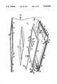
- FIG. 1is an isometric representation of a personal computer apparatus incorporating the present invention
- FIG. 2is an isometric representation of the personal computer apparatus of FIG. 1 in the closed condition
- FIG. 3is an exploded isometric representation of the personal computer apparatus of FIG. 1 illustrating the principal subassemblies thereof;
- FIG. 4is a rear elevational view of the computer chassis with the rear closure panel closed;
- FIG. 5is a rear elevational view similar to FIG. 4 but showing the rear closure panel horizontal;
- FIG. 6is an exploded isometric view of the computer display
- FIG. 7is an isometric view of the computer display with the back cover partially cut away
- FIG. 8is an enlarged partial sectional view of the display housing taken along line 8--8 of FIG. 3;
- FIG. 9is a partial plan view of the display housing
- FIG. 10is an enlarged partial sectional view of the display housing taken along line 10--10 of FIG. 3;
- FIG. 11is a partial plan view of the display base and display housing with the backing covers removed;
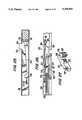
- FIG. 12is an enlarged isometric view of the circuit strip and connector employed in the computer display
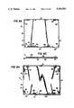
- FIG. 13is a partial plan view of the circuit strip and connector of FIG. 12;
- FIG. 14is a partial sectional elevational view of the circuit strip and connector taken along line 14--14 of FIG. 13;
- FIG. 15is a partial sectional elevational view similar to FIG. 14 showing the condition of the circuit strip and connector with the display housing in the closed position;
- FIG. 16is an isometric representation of the computer display in the detached, free-standing condition
- FIG. 17is a side elevational view of the detached computer display
- FIG. 18is a front elevational view of the computer display base
- FIG. 19is a side elevational view, partly in section, of the computer display base taken along line 19--19 of FIG. 18;
- FIG. 20is an enlarged side elevational view, partly in section, illustrating the computer display mounting connection to the chassis;
- FIG. 21is view taken along line 21--21 of FIG. 20;
- FIG. 22is a top plan view of the battery pack
- FIG. 23is a side elevational view of the battery pack
- FIG. 24is a bottom plan view of the computer chassis
- FIG. 25is an enlarged partial elevational view, partly in section, illustrating the battery pack latch mechanism
- FIG. 26is a partial top plan view of the latch mechanism of FIG. 25;
- FIG. 27is an isometric view of the latch mechanism actuator slide
- FIG. 28is a partial rear elevational view of the computer apparatus with its rear end elevated
- FIG. 29is a partial side elevational view of the computer apparatus with its rear end elevated
- FIG. 30is a partial side sectional view of the rear side of the chassis and closure panel
- FIG. 31is a partial plan view taken along line 31--31 of FIG. 30;
- FIG. 32is a front elevational view of the docking module
- FIG. 33is a rear elevational view of the docking module
- FIG. 34is a plan view of the docking module with parts broken away to illustrate the toggle latching mechanisms
- FIG. 35is an exploded isometric view illustrating the principal components parts of a toggle latching mechanism utilized with the docking module of FIG. 32;
- FIG. 36is a view taken along line 36--36 of FIG. 32 illustrating one form of a docking module connector mounting
- FIG. 37is a view taken along line 37--37 of FIG. 32 illustrating another form of docking module connector mounting.
- FIGS. 38 to 41are partial plan views of the docking module and computer chassis illustrating various stages of the mounting procedure.
- FIGS. 1 and 2 of the drawingsthere is shown a computer apparatus 10 particularly adapted for utilization alternately as a portable, so-called lap-top computer, or as a desk-top computer.
- the computer organizationcomprises four main sub-assemblies; namely a central processing unit (CPU) 12, a display 14, a battery pack 16 and a docking module 18.
- the display 14is mounted for pivotal movement with respect to the CPU 12 and, as shown in FIG. 2, when closed forms part of the computer enclosure structure.
- each of the sub-assemblies, including the display 14, the battery pack 16 and the docking module 18is detachable from the CPU 12 in order to enhance the versatility of application of the computer apparatus 10.
- CPUCentral Processing Unit
- the CPU 12comprises a metal casing structure forming a chassis or housing 20 containing a plurality of components, many of which are not germane to the present invention, as for example, data processing means, such as one or more microprocessor or microcomputer chips; a small random access memory; and means for electrically connecting the various components of the computer.
- Electric power to the computeris derived from the battery pack 16 during the lap-top mode of operation, while, for operating during the desk-top mode, power can be input from a house source of electric power.
- the chassis 20is formed of generally rectangularly positioned front and rear walls 22 and 24 and left and right side walls, 26 and 28, respectively, that extend between, and interconnect, a bottom wall 30 and a top wall 32.
- the top wall 32has a stepped configuration containing a keyboard 34 in the forward portion thereof and mounting the display 14 at a slightly elevated position in the rearward portion.
- a disc access opening 36is disposed in the right side wall 28 with a depressible disc release actuator 38 conveniently located adjacent thereto.
- the rear side wall 24 of the chassis 20(FIG. 4) is provided with a pivotally mounted single pole power switch 40 located adjacent the left side wall 26. Adjacent the switch 40 and closed by a closure cover 42 is a region 44 in which the connectors for various peripheral equipment are contained.
- Such connectorsinclude various female connectors, 46 through 54, having multiple prongs for connection with mating connectors of individual pieces of peripheral equipment, or with an assemblage of such connectors, such as contained in the docking module 18, discussed in detail hereinafter.
- the bottom surface 34 of the CPU 12may be provided with a plurality of resilient feet 229 to cushion engagement of the chassis 20 with a support surface when the battery pack 16 is removed.
- the display 14 in such apparatusprovides the output of computer graphics to the operator.
- the display 14is of the liquid crystal-type being contained in a display housing 60.
- the display housing 60is connected to the rearward portion of the top wall 32 of the CPU 12 via a base or jamb 62 that is adapted for releasable attachment to the CPU.
- the display housing 60is connected to the base 62 for pivotal movement between a position, shown in FIG. 2 as being essentially horizontal, in which the housing effectively covers and encloses, via a skirt 61, the computer top wall 32 in order to protect the keyboard 34. From the horizontal attitude the housing 60 is pivotable to a maximum angularly extended position for graphics display, shown in FIG.
- Position control meansenable the display housing 60 to be retained in any angular position between the horizontal position and its maximum extended position.
- Releasable latches 64each having an associated actuator 66, are retained in the left and right side walls, 26 and 28, for releasably securing the display housing 60 in its closed position.
- the display housing 60comprises an assembly of oppositely disposed metal panels formed of cast aluminum or magnesium-alloy and including front panel 68 and rear panel 70. Interposed between the panels 68 and 70 in sandwiched relation thereto, are a forwardly positioned liquid crystal display (LCD) plate 72 and an electric luminescent panel 74 therebehind. Surrounding the LCD plate 72 are rectangularly arranged printed circuit boards 76 that form part of the electrical connection between the CPU 12 and the display 14.
- LCDliquid crystal display
- the sub-assembly consisting of the plate 72 and circuit boards 76are resiliently cushioned by generally U-shaped shock mounts 78 disposed substantially at the intersecting corners of the sub-assembly and adapted to be received into seats 80 integrally formed on the interior surface of the front panel 68.
- connection arrangementthat comprises the interengagement of oppositely directed lips 82 and 84 (FIG. 8) that extend along the longitudinal edges of the respective panels that form the upper or free side of the display 14.
- the connection arrangementfurther includes along each of the remaining three sides of the housing 60 the provision on the oppositely facing, interior surfaces of the front and rear panels 68 and 70 of alternately spaced projections 86 containing longitudinal recesses 88.
- the projections 86 on the rear panel 70are integrally formed along the inturned panel edge 90 to face inwardly therefrom.
- the projections 86 on the front panel 68are formed as part of an integrally formed strip 92 spaced inwardly from the panel edge and upstanding from the interior surface of the panel with the projections 86 being disposed on the outwardly facing side of the strip.
- the projections 86 on the respective panelsare on alternate spacing and organized to be mutually interfitting when the panels are brought together in assembled relation.
- the recesses 88 in the respective projections 86are so arranged as to be axially aligned upon assembly of the panels so as to form an elongated opening for reception of a straight, elongated fastening pin 94.
- the fastening pins 94are of a diameter to be snugly received in the elongated opening formed by the aligned recesses 88.
- the pins 94at their rear ends, are provided with threads 95 that permit them to be attached to a tool (not shown) by which they can be rotated as they are inserted into their associated elongated opening. Rotating the pins in this manner facilitates their insertion and extension along the elongated openings. To further facilitate passage of the pins 94 through these openings their leading ends may be pointed as shown at 97 in FIG. 9.
- a closure plug 96may be installed to cover the threaded end of each pin 94 by resilient engagement with the wall of a counterbore 98 formed in the panels.
- the plugs 96are each sized to substantially fill the respective counterbores 98 and are located at the bottom ends of the respective side edges of the display housing 60 and at one end along the bottom or pivot side of the housing.
- These openings 98are formed by semi-cylindrical segments in the respective panels 68 and 70 and are completed when the panels are brought together upon assembly.
- the closure plugs 96are first removed from the respective openings 98 and the aforementioned tool threadedly attached to the end of the respective fastening pins 94 for their withdrawal from the openings in which they are disposed.
- the panels 68 and 70can be manipulated with respect to each other thereby disengaging the lips 82 and 84 and permitting the panels to be separated.
- the display housing 60is journalled for pivotal movement in the base or jamb 62, the latter being comprised of a metal casting containing integrally formed journals 100 and 102 (FIG. 11) disposed at opposite ends thereof and a cast metal cover 63 (not shown in FIG. 11) that closes the casting.
- a pivot shaft 104that is fixedly secured to the display housing 60 and that extends from one lateral end thereof, serves as the pivot axle.
- This shaft 104possesses the supplemental function of guidingly attaching a flexible circuit strip 106 that provides the electrical connection between the CPU 12 and the display 14, the details of which attachment are described hereinafter.
- This position control apparatus 109comprises an elongated cylindrical rod 110 formed of spring steel extending end-to-end between the lateral sides of the display assembly and received in a receptacle 112 formed in the display housing panel 68 adjacent the fastening pin 94 that secures the bottom edges of the housing panels 68 and 70.
- the rod 110contains a substantially perpendicular offset portion 114 that is received in a receptacle 116 formed by spaced projections cast along the side portion of the front panel 68.
- the rod 110contains a substantially perpendicular offset portion 120 that, as shown in FIG. 6, is angularly offset about 80° with respect to the offset portion 114.
- the offset portion 120is adapted to be received in a receptacle 122 (FIG. 11) formed in the base 62 by cast projections. It will be appreciated that the respective offset end portions 114 and 120 of the rod 110 serve to anchor opposite ends of the rod to the display housing 60 and base 62, respectively, so that the rod incurs torsional stressing during pivoting of the display housing with respect to the base.
- the rod 110is designed to contain a torsional prestress selected such that it is essentially zero psi when the display housing 60 is disposed about 10° beyond its vertical position with respect to the upper surface 32 of the CPU 12.
- a torsional prestressselected such that it is essentially zero psi when the display housing 60 is disposed about 10° beyond its vertical position with respect to the upper surface 32 of the CPU 12.
- the stress profileis such that, when the latches 64 are actuated to release the housing 60 from the sides of the chassis 20, the housing will automatically spring to a slightly raised position above the upper surface of the chassis. This facilitates its being manually gripped for further manipulation.
- the rod 110telescopically receives the pivot sleeve 108 about the offset portion 120.
- the pivot sleeve 108when assembled on the rod 110 extends beyond the end of the display panels, 68 and 70, and is received in the journal 122 provided in the casting forming the base 62, wherein it is anchored in place by the assembly of the cover 63 and whereby it forms the other display pivot axle.
- the band brake 130is formed of resilient material, such as spring steel, and has a portion 132 formed as a segment of a cylinder that surrounds the pivot sleeve 108 about three-fourths of the way around its circumference.
- the brake 130has divergent ends 134 that extend from the cylindrical portion 132 and, when constricted upon assembly of the display panels 68 and 70, cause the cylindrical portion to frictionally engage the pivot sleeve 108.
- the friction retention force generated by the band brake 130is effective to retain the display 60 in any angular position between its initial, slightly raised, unlatched position and its maximum full open position, thereby to enable adjustment of the display in any angular position between these positions.
- the displayis held in its various angular positions principally by the friction force developed by the cylindrical portion 132 of the band brake 130 on the pivot sleeve 108.
- the torsion rod 110besides being useful in reducing the gravitational effects of the display 14 and thereby the amount of effort required to move it, interacts with the band brake 130 to reduce significantly the amount of friction force necessary to be generated by the band brake for retaining the display. Therefore, the size of the respective elements required to retain the display is minimized such that the display housing structure required for their containment is small.
- the electrical interconnection between the CPU 12 and the display 14is effected by a flat, flexible plastic circuit strip 106, of generally known construction, in which a plurality of electrical conductors are embedded.
- the circuit strip 106has one terminal end electrically connected to a multi-pronged terminal plug 138 centrally disposed in the base 62 of the display 14.
- the plug 138is adapted for connection in a mating plug (not shown) that is accessible through opening 140 in the upper wall 32 of the CPU 12 which is closed by depressible, spring-biased closure covers 142.
- the strip 106is adapted for connection to one or more of the printed circuit boards 76.
- the strip 106contains a pair of parallel leg portions 142 and 144 and a nexus portion 146.
- One leg portion 144extends to the nexus portion 146 from the terminal plug 138 and is fixedly secured in a track 148 formed in the base casting upon assembly of the base 62.
- the other leg portion 142extends to the nexus portion 146 of the strip from that terminal end which is connected to the circuit board 76.
- the leg portion 142is fixedly secured between the panels 68 and 70 that form the display housing 60 and is adapted to undergo movement with the housing when it is pivoted about the base 62.
- a flex bushing 150that defines the pivot shaft 104.
- the flex bushing 150has a body having a generally cylindrical section 152 and a generally rectangular sided anchor section 154 separated by an enlarged diameter flange 156.
- the bushing 150is retained between the display housing panels 68 and 70 with the anchor section 154 being seated in a cast receptacle in the panels so that the bushing remains stationary with respect to the display housing 60 for angular movement therewith.
- the cylindrical section 152 of the bushing bodyextends from an opening in the housing and is mounted for pivotal movement in the journal 100 formed in the casting defining the display base 62. This opening is effectively closed by the close proximity of the flange 156 on the bushing body to the opening. It will be appreciated that the bushing body thus forms the other pivot axle for the display 14.
- the body of bushing 150extends in a direction transversely of the nexus portion 146 of the circuit strip 136, thus to grasp the strip 136 substantially along the longitudinal axis of the leg portion 142.
- Grasping of the strip 106 in this manneris effected by the fact that the bushing body contains a longitudinal slot 157 produced by the body's being fabricated in half sections that are joined by a flexible connector strip 158 that permits the sections to be folded upon each other.
- the attached portion of the strip 106is retained on the bushing 150 by being sandwiched between the respective half sections.
- the cylindrical section 152 of the bodyis formed as a recess that is shouldered at each end, as shown at 160, within which recess the exposed part of the nexus portion 146 of the circuit strip 106 is wound as the bushing rotates in journal 100 upon pivotal movement of the display 14.
- FIGS. 14 and 15The action of the strip 106 formed by the nexus portion 146 is best illustrated in FIGS. 14 and 15, wherein it is evident that sufficient slack is made available in the strip to create an undulation or wave of sufficient longitudinal extent to permit the bushing body 150 to undergo about 135° of rotation in the journal 100 without applying undue tension to the strip material.
- the material forming the nexus portion 146 of the circuit strip 106winds upon the reduced diameter portion 152 of the bushing and is confined thereto by the shoulders 160 formed at the respective ends of the recess.
- the strip materialis caused to undergo controlled movement as the display 14 moves with respect to the base 62, thereby preventing the creation of snarls in the strip that might create damage or breakage thereof or might, otherwise, cause a system malfunction.
- the display 14, including the housing 60 and base 62can be completely detached from the CPU chassis 20 and made to be independently standing.
- This desirable featureis obtained by the provision, on the underside of the base 62 adjacent opposite ends thereof, of locking cams 162 fixedly attached to operating levers 164.
- the organizationis such that, when the display 14 is detached from the CPU 12, the operating levers 164 of the locking cams 162 advantageously serve as support legs for the free standing assembly and the locking cams 162 serve as support feet to raise the front end of the assembly with respect to its back end. In this way a greater degree of inclination can be imparted to the display housing 60, to both enhance viewing of the projected graphics and to improve stability of the free standing structure by moving its center of gravity rearwardly.
- FIGS. 11 and 18depict a plan view and a rear view, respectively, of the base 62 on which the locking cams 162 are mounted.
- the cams 162comprise bodies having parallel, somewhat elongated, linear sides 166 and rounded, generally circular ends 168.
- the cam bodiesare integrally formed on one end of the respective levers 164, with the assembly being connected for pivotal movement via a spring-biased fastener 163 to the casting forming the base 62.
- the levers 164are in their extended positions, and normal to the longitudinal axis of the base 62, the sides 166 of the cams 162 are caused to be aligned with the base axis.
- the levers 164are rotatable 90° to be received in openings 169 formed in the base 62, whereupon the sides 166 of the cams 162 are made to be disposed perpendicular to the base axis, thus to effect a locking mode, as hereinafter explained.
- the top wall 32 of the chassis 20 adjacent its rear endcontains three openings, indicated as the centrally disposed plug opening 140 and openings 172 spaced on opposite sides of the central opening 140.
- the central opening 140provides access to a female terminal connector (not shown) for the terminal plug 138 located on the underside of the housing base 62.
- the plug 138attaches directly to the mating female connector in the chassis 20.
- an elongated electrical connector indicated as 174 in FIG. 16is made to connect between the respective aforementioned terminal connectors.
- the electrical connector 174may be arranged to carry a body 175 forming a foot for stabilizing the display 14 when it is separated from the computer 12.
- Each of the openings 172is, as shown, rectangular in shape and is closed by a flat closure plate 176 that is mounted in cantilever-fashion via a base 178 having openings that move along a pair of depending sleeved posts 180 and that is biased upwardly by means of springs 182 positioned between the head of the posts 180 in each pair and the base that moves therealong.
- the levers 164are moved to their extended position perpendicular to the base axis. This positions the locking cams 162 with their sides 166 parallel to the base axis and in a position to be received by the respective openings 172 in the upper surface 32 of the chassis 20.
- the base 62is caused to be moved downwardly toward the chassis top wall 32 such that the cams 162 simultaneously enter the openings 172 and the plug 138 enters the opening 140 pivoting the closures 142 open therein for connection of the plug 138 to the mating female plug.
- the computer apparatus 10is equipped with a battery pack 16 of particular design that is releasable from attachment to the CPU 12 for recharging or for other purposes.
- the battery pack 16comprises a plurality of rechargeable cells (not shown) that are housed within a container 186 of reduced vertical dimension having generally rectangular shaped, parallel upper and lower walls 188 and 190 that are interconnected by rectangularly arranged upstanding front, rear and oppositely spaced side walls 192, 194, 196 and 198, respectively.
- a contact assembly 199 formed of a plurality of resilient contact elementsis here shown as being located adjacent the corner formed by the intersection of the rear wall 194 and side wall 196.
- the contact elements 199a of the assembly 199are arranged to resiliently engage contact elements (199b) (FIG. 24) disposed on the chassis bottom wall 34 in overlying relation to the contact assembly on the battery pack 16 when in its latched, operative position.
- the securing members 200are formed of generally flat bodies each having its longitudinal axis extending parallel to the adjacent battery side wall.
- the members 200are adapted to be received in slots 20 provided in the bottom wall of the CPU chassis 20.
- the slots 201have a shape corresponding to the sectional shape of the members 200, but are slightly elongated in the longitudinal direction and have their hook-forming openings 202 facing in the direction of the battery rear wall 194.
- the particular shape of the securing members 200dictates that, upon both installation and removal of the battery pack 16 to and from the bottom wall 34 of the chassis 20, there will be relative sliding contact between the contact elements 199a on the battery pack body 186 and the mating contacts 199b on the chassis bottom wall 34 so that damaging oxide accumulation on the respective contacts is prevented.
- a releasable latching mechanismis employed to couple the battery pack 16 to the chassis 20 of CPU 12.
- the latching mechanism 203comprises a depressible detent 204 that is adapted to be received in a mating slot 205 in the bottom wall 34 of the chassis.
- the detent 204is integrally formed on an operator arm 206 having a composite shape that enables it to be retained within the battery pack container structure for pivotal movement; to be spring biased; and to be cam actuated within a restricted space.
- the operator arm 206is formed of a sheet metal body that is housed within a cast portion 208 of the battery pack frame structure, from which the detent 204 is vertically extensible and retractable by pivotal movement of the operator arm.
- the operator arm 206is formed at one end with a substantially circularly formed pivot portion 210 that rests in a pivot seat 212 of complementary shape in the cast portion 208.
- the arm 206contains a longitudinal extension 214, the bottom surface of which engages a spring 216 that is contained within a spring seat 218 in the cast portion 208 and that normally biases the engaged end of the arm upwardly.
- the arm 206possesses a cam surface 220 that is inclined upwardly in the direction of the detent 204 and adapted for reception of a movable boss 222 formed on an actuator slide 224.
- the actuator slide 224contains two laterally spaced body portions 226 and 228 joined by connector 227.
- the spacing between the body portions 226 and 228 and the position of the connector 227 therebetweenis such as to permit the actuator slide 224 to be retained for longitudinal sliding movement on the battery pack frame structure.
- the body portion 226 containing the boss 222also contains a post 232 to which one end of a spring 234 is attached. At its other end the spring 234 is attached to a post 236 on the cast portion 208 such that the actuator slide 224 is normally biased to its retracted position with the boss 222 positioned in the deepest part of the recess forming the cam surface 220 so that the detent 204 is normally located in its vertically extended position.
- the other actuator body portion 228is disposed exteriorly of the battery pack container and may be provided with a knurled, or otherwise roughened surface, to facilitate its manual operation.
- the actuator 224is manually moved to the right as it appears in FIGS. 22, 25 and 26 so as to pivotally depress the operator arm 206 and withdraw the detent 204 from the mating slot 205 in the CPU chassis. Withdrawal of the detent 204 from its mating slot 205 permits the battery pack 16, and thus the securing members 200, to be moved rearwardly for release of the members from the slots 201 in which they extend.
- This longitudinal movement of the battery pack with respect to the chassis 20effects a sliding action of the contact elements 199a on the battery pack with the contact elements 199b on the chassis, thereby advantageously wiping any accumulated metal oxide from the surface of the respective contacts.
- the detent 204will, when the facing surfaces of the chassis and the battery pack bear against each other, be forced downwardly depressing the operator arm 206 against the spring 216.
- the detent 204being upwardly biased by spring 216 will automatically enter the mating slot 205 to secure the battery pack to the chassis.
- the facing surface 188 of the body 186 of the battery pack 16contain recesses 230 formed and located to provide clearance for the respective feet 229 on the bottom surface 34 of computer chassis 20.
- the chassis 20 of CPU 12in the region 44 of the rear wall 24, mounts the various aforementioned electrical connectors including principally the expansion bus connector 46, video connector 48, a connector 25 for a printer or the like, modem connections 52, and a keyboard connection 54.
- Other connectionssuch as that indicated as 53 for a mouse, and connector ports 55 to accommodate connection of other compatible apparatus can also be provided.
- the computer power switch 40Also disposed on the rear wall 24 is the computer power switch 40, the actuation of which activates the computer, either by power from the battery pack 16 or from an external power source.
- the region 44 of the rear wall that contains the respective electrical connector members 46 through 55is made to be slightly recessed from the lateral end portions of the rear wall. Closing the recessed region 44 is a closure panel 42 formed by a plate 246, the external surface of which is substantially coplanar with the adjacent portions of the rear wall.
- the plate 246is mounted via pivot pins 248 disposed at opposite ends of the panel lower portion and journalled in the facing sides 250 of the recess that forms region 44.
- the plate 246is angularly displaceable through a range of movement of about 180°, from the vertically upright position shown in FIGS. 4 and 30, in which it serves to enclose and cover the region 44, to the vertically downturned position of FIGS. 28 and 29 in which the plate 246 serves as a support standard for raising the rear of the chassis 20, thereby to permit the CPU 12 to be supported in an inclined attitude, if desired.
- the plate 246, as shown in FIG. 5,is also arranged to assume a third position, intermediate the other two positions, in which it is disposed substantially parallel to the bottom wall 32 of the CPU chassis 20. In this position the plate is effective to permit access to the various connectors in the region 44 of the chassis rear wall 24 with the chassis 20 oriented in an essentially horizontal position.
- Mechanismis provided to effectively secure the plate 246 in each of its three operative positions.
- This mechanismcomprises, at each opposite end of the plate 246 adjacent the pivot pins 248, a camming surface, indicated generally as 252, having four rectangularly disposed sides, three of which, indicated as sides 254, 256 and 258, are cam surfaces engageable by a spring biased follower 260.
- Each follower 260comprises a pressing foot 262 that is separated by an enlarged shoulder 264 from a guide post 266.
- the pressing foot 262 on each followeris adapted to extend through an opening 268 in the chassis rear wall 24 in order to access the surface 252.
- the follower 260is biased outwardly by a spring 270 that surrounds the guide post 266 and extends between the shoulder 264 and a spring retainer 272 integrally formed on, and upstanding from, the interior surface of the chassis bottom wall 30.
- the movement of the pressing foot 262is guided by a pair of retainers 272 that are also upstanding from the interior surface of chassis wall 30.
- the side 254 of the camming surface 252 of the cover 427is engaged by the pressing foot 262 of the follower 260 with the closure plate 246 in its vertically upright position.
- the spring force imposed on the follower 260 by spring 270is of the order of magnitude of about 50 pounds to, thus, secure the plate 246 in the selected position.
- the follower 260is depressed against the spring 270, to be returned to pressing engagement with the surfaces 256 and 258 when the plate has been moved to dispose one or the other of the surfaces to a disposition normal to the axis of the pressing foot.
- the camming surface 252is advantageously arranged to permit relatively easy movement of the plate 246 between its vertically upright position and its intermediate position parallel to the chassis bottom wall 30. This relative ease of movement is effected by a depression 274 at the intersection of the sides 254 and 256. Such depression may be formed by either a curved surface extending between the two sides or, as shown, by a linear diagonal surface that intersects the two sides at about 45°.
- the intersection between the sides 256 and 258 of camming surface 252is maintained essentially at right angles. This is to increase the force required to depress the follower 260 and, concomitantly, the force necessary to move the plate 246 between its intermediate and its standard-forming position. More importantly, this device increases the retrograde force required to move the cover plate 246 between its standard-forming position back to its intermediate position, so as to reduce the danger of collapse of the support for the rear end of the chassis 20 when it is in its raised position.
- the configuration of the camming surface 252in cooperation with the follower 260, is such as will permit relative ease of movement of the closure plate 246 from its position closing the recessed region 44 of the chassis rear wall 24 to its open position.
- the configuration of the camming surface 252is also such as will render it difficult for the plate 246 to be accidently dislodged from its vertically downturned position, where a sudden collapse of the support standard could damage the computer apparatus.
- the docking module 18whose function it is to effect connection between the computer chassis 20 and various pieces of ancillary equipment without the need for individual cable connections, thereby to facilitate conversion of the computer between its lap-top mode of operation and its desk-top operating mode.
- the docking module 18comprises a metallic casing 283 formed by the assembly of an upper shell 284, a lower shell 286, a front bezel 288 and a rear bezel 290.
- the opposite side surfaces 292 and 294 of the docking module 18are formed by the cooperation between perpendicularly offset wall portions such as those indicated as 286a and 286b that extend from the upper and lower shells 284 and 286, respectively.
- toggle latch mechanisms 296,mounted on the respective side surfaces 292 and 294 and separated from the interior region of the docking module by an arcuately formed shielding partition 295 are toggle latch mechanisms 296, each consisting principally of a latch hook 300, and a toggle lever 302, and each of which is formed of a rigid material. Since the sole structural difference existing between the respective toggle latch mechanisms 296 is the opposite facing disposition of the ripping projections 304 on the latch hooks 300 only one such toggle latch mechanism will be described in detail.
- the toggle lever 302is a substantially U-shaped member having a body 306 containing oppositely spaced arms 308 and 310.
- the arms 308 and 310 adjacent their leading endscontain axially aligned pivot holes 312 adapted for reception on pins 314 which are integrally formed on the upper and lower shells 284 and 286, respectively, in oppositely facing relation to one another.
- the space between the arms 308 and 310receives the latch hook 300 that is connected via a pivot pin 316 to the toggle lever 320 and that has formed thereon the inturned hook-like gripping projection 304.
- Each toggle latch elementis spring biased by a compound leaf spring assembly 318 that is fixedly attached at one end in a recess 320 integrally formed in standards 322 cast in the upper and lower shells 284 and 286, respectively.
- Each spring assembly 318comprises a central spring element 324 whose free end is angularly offset and adapted to engage a cam element 326 formed on the rear end 328 of the latch hook 300 and operable to bias the end 328 outwardly and, thus, the leading end that contains the projection 304 inwardly.
- Straddling the central spring element 324is a lever spring 330 adapted at its free end to alternately engage angularly disposed cam surfaces 332 and 334 formed on a cam nose 336 that is integrally formed on the toggle lever body 306 extending between the arms 08 and 310.
- the disposition of the cam surfaces 332 and 334 on the cam nose 336is such as, in cooperation with the lever spring 330, to biasly retain the lever 02 alternatively in its angularly outer or released position and in its latching or angularly inner position.
- the toggle mechanisms 296 and 298are arranged to secure the docking module 380 to the computer chassis 20 by the cooperation of the projections 304 on the latch hooks 300 with recessed depressions 340 (FIG. 29) formed on the left and right side walls 26 and 28 of the computer chassis 20 adjacent the rear ends thereof and formed to receive and grip the projections 304 so as to draw the docking module 18 and the computer chassis 20 toward each other and to secure them together.
- the location of the respective depressions 340 vis-a-vis the toggle mechanisms 296 and 298is such that the mechanisms operate to emit an audible signal when the projections 304 formed on the leading ends of the respective latch hooks 300 enter their respective associated depressions 340 to indicate that all of the complementary connectors on the docking module 18 and computer chassis 20 are properly aligned so as to permit actuation of the toggle levers 302 to draw the respective apparatus together and thereby further extend the pins on the male connectors into the receptacles on the female connectors without danger of damaging any of the connectors.
- the biasing force of the central spring elements 324 on the latch hooks 300accordingly serve, not only to bias the projections 304 inwardly into the inserted relation with the depressions 340 but, do so with such force that an audible noise results which serves as the aforementioned signal.
- the face of the front bezel 288mounts connectors that complement the connectors 46 through 55 mounted on the rear wall of the chassis 20.
- those connectors mounted on the front bezel 288 and indicated by the same numeral but with a prime superscript as the reference numeral that designates the connector on the CPU 12 with which it connectsare adapted to float to a limited degree by the provision of slightly oversized holes in which the respective connectors are mounted, thereby to impart a self-alignment feature to the concerned connectors.
- FIGS. 36 and 37depict examples of the two typical forms of connector mountings existing in the docking module.
- FIG. 36is shown a multi-pin connector similar to the connector 55', adapted for reception in a mounting hole 344 of slightly oversized, conforming shape.
- the connector 55'comprises a frame 346 adapted for reception of screws 347 at the opposite lateral ends thereof.
- the mounting hole 344is provided with oppositely spaced lateral recesses 348 into which is inserted a flexible grommet 350 configured to fit snugly in the recess in concentric, surrounding relation to the neck of a tubular nut 352.
- the grommets 350 and nuts 352are inserted into the recesses 348 in alignment with openings in a flange 354 for reception of screws 347.
- FIG. 37depicts another form of electrical connector 358 typically formed of plastic material whose body 360 is provided at one end with an outwardly extending flange 362 adapted to engage one side of the inturned flange 364 that extends about the periphery of the mounting hole 366 in the front bezel 288.
- a plurality of flexible fingers 368Spaced rearwardly from, and extending toward, the flange 362 are a plurality of flexible fingers 368 whose gripping faces oppose the flange 362 and in cooperation therewith are adapted to engage the opposite side of the flange 364.
- Appropriate sizing of the hole 366 vis-a-vis the body 360provides the connector 358 with a limited degree of float both horizontally and vertically on the docking module 18 thus to impart the connector with a self-alignment capability.
- Assisting in the alignment of the electrical connectors on the docking module 18 with those on the chassis 20are a pair of alignment pins 370 that are flexibly secured to the front bezel 288 by a spring or other flexible connection.
- the pins 370are desirably disposed on laterally oblique spacing on the front bezel and extend forwardly from the surface thereof to be received in mating holes 372 formed in the chassis rear wall 24.
- a pusher linkage 374comprising an actuating lever 376 accessible from the rear face of the docking module and an operating lever 378 that protrudes through an opening in the front bezel 288 to engage the switch 40 on the CPU chassis 20.
- the levers 376 and 378are each mounted for pivotal movement on pivot pins 380 and 382 upstanding from the front and rear edges, respectively, of the lower shell 286.
- a link 384extends between and interconnects corresponding arms on the respective levers such that a pivoted action imposed on the actuating lever 376 will be directly imparted to the operating lever 378 and, concomitantly, to the power switch 40 on the computer chassis.
- the operation of the described docking module 18is as follows. In a typical application the docking module 18 will be disposed on a support surface at a location at which desk-top operation of the computer apparatus is intended.
- To each of these connectors on the rear bezel 290are connected via appropriate cabling the ancillary equipment intended for use with the computer 10. Such equipment may include a video apparatus, a printer, a modem, etc. It will be appreciated that cabling, once attached to the docking module 18, is intended to remain essentially permanently attached regardless of whether the computer 10 is attached to the docking module, or not.
- the electrical connectors mounted on the front bezel 288complement and are electrically connected to those on the rear bezel 290. They also complement those on the computer chassis rear wall 24. Consequently, the mating connection of the connectors on the computer chassis 20 to those on the docking module 18 will effectively connect the computer 10 to all apparatus from which cabling is extended and attached to the connectors on the docking module rear bezel 290.
- the effect of thisis to greatly facilitate conversion of the computer from its lap-top or portable, operating mode to a desk-top mode, or vice-versa, in that the need to independently and individually make or break connections to the various equipment attached to the computer is eliminated. Instead, only a single connection need be made of the computer 10 to the docking module 18 that simultaneously effects all of the connections to be made.
- the front of the docking module and the rear of the chassisare placed in a face-to-face relation and the alignment pins 370 on the docking module are caused to enter the mating holes 372 in the computer chassis 20 (FIG. 39).
- the computer chassis 20 and the docking module 18are thereafter moved closer together with the projections 304 on the latch hooks 300 of the toggle latch mechanisms in sliding contact with the wall surfaces rearwardly of the depressions 340.
- the interstitial space between the docking module 18 and the computer chassis 20is such that the projections 304 on the latch hooks 300 are caused to enter the depressions 340 in the chassis side walls 26 and 28.
- the latch hooks 300are spring biased by the central spring elements 324, the projections 304 are caused to enter the depressions 340, as shown in FIG.
- the levers 302are released from their locked position of FIG. 41, whereupon, in returning to their open position under the influence of the spring 330 the reactive force generated between the tip 303 of the hook 300 and the adjacent edge of the depression 340 in the chassis 20 effects a slight retrograde movement of the docking module from the chassis.
- the lever 302is moved slightly forwardly from its open position whereupon by action of the cam surface 305 on the front bezel 288 and the follower 307 on the hook 300, the latter is urged laterally outwardly from the depression so as to enable final separation of the docking module from the computer.
- the invention described herein and embodied in the claims hereofprovides effective apparatus for controlling the pivotal movement of the display 14 with respect to the CPU 12 to enable the display to be retained in any angular position within its controlled range of movement on the CPU chassis thus to permit the user to adjustably position the display for the elimination of glare, or for other purposes.
- the apparatusis advantageously simple in design and compact of form so as to permit its being contained within the display housing without requiring any enlargement of the housing to accommodate the presence of the apparatus.
Landscapes
- Engineering & Computer Science (AREA)
- Computer Hardware Design (AREA)
- Theoretical Computer Science (AREA)
- General Engineering & Computer Science (AREA)
- Physics & Mathematics (AREA)
- Human Computer Interaction (AREA)
- General Physics & Mathematics (AREA)
- Mechanical Engineering (AREA)
- Mathematical Physics (AREA)
- Power Engineering (AREA)
- Computer Networks & Wireless Communication (AREA)
- Devices For Indicating Variable Information By Combining Individual Elements (AREA)
Abstract
Description
Claims (20)
Priority Applications (1)
| Application Number | Priority Date | Filing Date | Title |
|---|---|---|---|
| US07/684,755US5196993A (en) | 1989-03-06 | 1991-04-15 | Removable stand alone display for laptop computer |
Applications Claiming Priority (2)
| Application Number | Priority Date | Filing Date | Title |
|---|---|---|---|
| US07/319,157US5028025A (en) | 1989-03-06 | 1989-03-06 | Torsion bar and band brake |
| US07/684,755US5196993A (en) | 1989-03-06 | 1991-04-15 | Removable stand alone display for laptop computer |
Related Parent Applications (1)
| Application Number | Title | Priority Date | Filing Date |
|---|---|---|---|
| US07/319,157DivisionUS5028025A (en) | 1989-03-06 | 1989-03-06 | Torsion bar and band brake |
Publications (1)
| Publication Number | Publication Date |
|---|---|
| US5196993Atrue US5196993A (en) | 1993-03-23 |
Family
ID=26981872
Family Applications (1)
| Application Number | Title | Priority Date | Filing Date |
|---|---|---|---|
| US07/684,755Expired - LifetimeUS5196993A (en) | 1989-03-06 | 1991-04-15 | Removable stand alone display for laptop computer |
Country Status (1)
| Country | Link |
|---|---|
| US (1) | US5196993A (en) |
Cited By (107)
| Publication number | Priority date | Publication date | Assignee | Title |
|---|---|---|---|---|
| US5341929A (en)* | 1993-05-13 | 1994-08-30 | Stefancin Jr Ronald J | Keyboard tray assembly |
| US5363227A (en)* | 1989-05-31 | 1994-11-08 | Fujitsu Personal Systems, Inc. | Liquid crystal display mounting structure |
| US5411416A (en)* | 1994-07-29 | 1995-05-02 | The Whitaker Corporation | Docking connector unit |
| US5422751A (en)* | 1992-10-14 | 1995-06-06 | Apple Computer, Inc. | Liquid crystal display assembly employing front bezel, frame holding liquid crystal cell attached to bezel, and light source and back plate attached to bezel |
| US5548478A (en)* | 1994-07-25 | 1996-08-20 | Khyber Technologies Corporation | Portable computing device having an adjustable hinge |
| US5566088A (en)* | 1994-06-13 | 1996-10-15 | Motorola, Inc. | Modular radio test system and method |
| US5574252A (en)* | 1994-03-08 | 1996-11-12 | Physio-Control Corporation | Method and apparatus for electrically and mechanically interconnecting electrical components |
| US5574477A (en)* | 1993-09-30 | 1996-11-12 | Sanyo Electric Co., Inc. | Direct-vision/projection type liquid-crystal display |
| US5608863A (en)* | 1991-04-23 | 1997-03-04 | Seiko Epson Corporation | Portable computer system having a display housing providing a stacked structure to accommodate display panel, circuit board, rechargeable sheet battery, charging circuit and terminal |
| US5619397A (en)* | 1994-09-29 | 1997-04-08 | Kabushiki Kaisha Toshiba | Electronic device system including a portable electronic device having a handwriting input device locked to an expansion station when the power switch of the portable electronic device is turned on |
| US5666261A (en)* | 1995-09-25 | 1997-09-09 | At&T Global Information Solutions Company | Honeycomb celled-sheet layer composite panel for monitoring an LCD to a laptop computer |
| US5668570A (en)* | 1993-06-29 | 1997-09-16 | Ditzik; Richard J. | Desktop computer with adjustable flat panel screen |
| US5725324A (en)* | 1995-12-21 | 1998-03-10 | Tandem Computers Incorporated | Module latch assembly |
| US5729429A (en)* | 1996-02-20 | 1998-03-17 | Margaritis; Georgios | Ergonomic laptop computer having display positioning supports |
| US5745340A (en)* | 1994-12-19 | 1998-04-28 | Landau; Jennifer | Separable display of computer generated information |
| US5751546A (en)* | 1996-06-21 | 1998-05-12 | Itronix Corporation | Cradle assembly for portable computing devices and method |
| US5751545A (en)* | 1996-01-17 | 1998-05-12 | Samsung Electronics Co., Ltd. | Desktop personal computer with an easy assembly structure |
| US5793606A (en)* | 1994-08-23 | 1998-08-11 | Packard Bell Nec | Removable LCD and stand assembly |
| US5796576A (en)* | 1995-10-04 | 1998-08-18 | Samsung Electronics Co., Ltd. | Notebook computer having a hinge device enabling a display unit to be separable from a main body |
| US5801527A (en)* | 1994-07-26 | 1998-09-01 | Tokyo Electron Limited | Apparatus and method for testing semiconductor device |
| US5805415A (en)* | 1996-10-03 | 1998-09-08 | Hewlett-Packard Company | Detachable flat panel computer display and support |
| US5815735A (en)* | 1996-04-29 | 1998-09-29 | Compaq Computer Corporation | Portable computer with removable display screen using removably mateable connectors to form the sole supporting interconnection between the computer base portion and display screen structure |
| US5914853A (en)* | 1996-02-29 | 1999-06-22 | Kabushiki Kaisha Toshiba | Portable computer |
| US5918957A (en)* | 1998-09-04 | 1999-07-06 | Digital Equipment Corporation | Pivoting door system for a portable computer |
| USD413574S (en) | 1997-10-14 | 1999-09-07 | Sony Corporation | Connector |
| US5983073A (en)* | 1997-04-04 | 1999-11-09 | Ditzik; Richard J. | Modular notebook and PDA computer systems for personal computing and wireless communications |
| US6002582A (en)* | 1998-01-05 | 1999-12-14 | Dell U.S.A., L.P. | Adapter for various LCD sizes in a computer |
| US6008983A (en)* | 1997-07-29 | 1999-12-28 | Yen; Jung-Chuan | Adjusting device for a screen of a computer |
| US6034867A (en)* | 1996-06-20 | 2000-03-07 | Samsung Electronics Co., Ltd. | Portable computer having a locking assembly |
| US6094340A (en)* | 1997-05-27 | 2000-07-25 | Samsung Electronics Co., Ltd. | Method and apparatus of coupling liquid crystal panel for liquid crystal display |
| US6142593A (en)* | 1997-04-25 | 2000-11-07 | Samsung Electronics Co., Ltd. | Docking station with adjustable guide rails |
| US6144552A (en)* | 1999-04-26 | 2000-11-07 | Emc Corporation | Handheld computer system |
| US6151012A (en)* | 1995-11-16 | 2000-11-21 | Bullister; Edward | Multifunctional portable computing device with special housing |
| US6163452A (en)* | 1999-11-05 | 2000-12-19 | Dell Usa, L.P. | Display screen assembly apparatus and method |
| US6175502B1 (en)* | 1998-02-20 | 2001-01-16 | Knuerr-Mechanik Fuer Die Elektronik Aktiengesellschaft | Equipment arrangement |
| US6198624B1 (en) | 1998-06-01 | 2001-03-06 | Georgios Margaritis | Ergonomic laptop display positioning supports |
| US6246573B1 (en) | 2000-01-20 | 2001-06-12 | Cieos, Inc. | Operatory computer with portable display |
| US6263391B1 (en)* | 1998-09-24 | 2001-07-17 | Adaptec, Inc. | Modular bus bridge |
| US6304431B1 (en)* | 1997-10-07 | 2001-10-16 | Samsung Electronics Co., Ltd. | Portable computer system having ergonomic keyboard and detachable display unit |
| US6317316B1 (en) | 1999-10-06 | 2001-11-13 | Dell Usa, L.P. | Method and system for integrated personal computer components |
| US6381128B1 (en) | 2000-07-17 | 2002-04-30 | Russel G. Kramer | Ergonomic portable computer |
| US6411503B1 (en) | 1996-10-11 | 2002-06-25 | Fujitsu Limited | Portable type information apparatus |
| US6445385B1 (en)* | 1998-06-15 | 2002-09-03 | Samsung Electronics Co., Ltd. | Assembly structure of display of electronic appliance |
| US6460947B1 (en)* | 1999-07-26 | 2002-10-08 | Compaq Information Technologies Group, L.P. | Interchangable battery pack for a portable computer |
| US6519143B1 (en)* | 1999-09-17 | 2003-02-11 | Nec Corporation | Docking station |
| US6539499B1 (en) | 1999-10-06 | 2003-03-25 | Dell Usa, L.P. | Graphical interface, method, and system for the provision of diagnostic and support services in a computer system |
| US20030061684A1 (en)* | 2001-09-28 | 2003-04-03 | Hironori Tanaka | Electronic apparatus |
| US6556431B1 (en) | 1999-10-06 | 2003-04-29 | Dell Usa, L.P. | System and method for converting alternating current into direct current |
| US6560100B1 (en) | 1996-10-24 | 2003-05-06 | Fujitsu Limited | Portable computer equipped with add-on battery |
| US6560726B1 (en) | 1999-08-19 | 2003-05-06 | Dell Usa, L.P. | Method and system for automated technical support for computers |
| US6563698B1 (en)* | 1999-10-06 | 2003-05-13 | Dell Usa, L.P. | System and method for providing a computer system with a detachable component |
| US6564220B1 (en) | 1999-10-06 | 2003-05-13 | Dell Usa, L.P. | System and method for monitoring support activity |
| US6574615B1 (en) | 1999-10-06 | 2003-06-03 | Dell Usa, L.P. | System and method for monitoring support activity |
| US6598223B1 (en) | 1999-10-06 | 2003-07-22 | Dell Usa, L.P. | Method and system for installing and testing build-to-order components in a defined configuration computer system |
| US6606716B1 (en) | 1999-10-06 | 2003-08-12 | Dell Usa, L.P. | Method and system for automated technical support for computers |
| US20040001306A1 (en)* | 2002-06-27 | 2004-01-01 | Oakley Nicholas W. | Transformable computing apparatus |
| US6697055B1 (en) | 1995-11-16 | 2004-02-24 | Edward Bullister | Multifunctional portable computing device with special housing |
| US20040048672A1 (en)* | 2002-09-09 | 2004-03-11 | Intec Inc. | Video display unit for video game console |
| US20040098515A1 (en)* | 2000-09-06 | 2004-05-20 | Babak Rezvani | Systems and methods for the automatic registration of devices |
| US6760708B1 (en) | 1999-08-19 | 2004-07-06 | Dell Products L.P. | Method and system for migrating stored data to a build-to-order computing system |
| US20040165346A1 (en)* | 1998-10-23 | 2004-08-26 | Kim Jong Hwan | Portable computer and method for mounting a flat panel display device thereon |
| US20040165345A1 (en)* | 1998-06-30 | 2004-08-26 | Young Un Bang | Portable information processing apparatus |
| US20040246667A1 (en)* | 2003-06-09 | 2004-12-09 | Arif Maskatia | Portable electronic device with a hinge mechanism |
| US20050083311A1 (en)* | 1995-09-26 | 2005-04-21 | Riddiford Martin P. | Computer with a pen or touch sensitive display |
| US20050135049A1 (en)* | 2003-12-17 | 2005-06-23 | Tatung Co., Ltd. | Portable computer standing support structure |
| US20050185365A1 (en)* | 2004-02-06 | 2005-08-25 | Kabushiki Kaisha Toshiba | Display apparatus |
| US20060020248A1 (en)* | 2004-07-26 | 2006-01-26 | Prescott Anthony D | Lacrimal insert having reservoir with controlled release of medication and method of manufacturing the same |
| US7103380B1 (en) | 1997-04-04 | 2006-09-05 | Ditzik Richard J | Wireless handset communication system |
| US7126588B2 (en) | 2002-06-27 | 2006-10-24 | Intel Corporation | Multiple mode display apparatus |
| US20070091552A1 (en)* | 2005-08-12 | 2007-04-26 | Wei-Kuang Liang | Notebook computer with detachable display unit |
| US7281698B2 (en) | 2002-08-23 | 2007-10-16 | Case Logic, Inc. | Multi-positionable notebook computer case |
| USD579451S1 (en)* | 2007-01-05 | 2008-10-28 | Oqo, Inc. | Computer docking assembly |
| USD579890S1 (en)* | 2005-12-22 | 2008-11-04 | Coby Electronic Corporation | Portable DVD player with external battery |
| US20100053027A1 (en)* | 2008-08-29 | 2010-03-04 | James Ian Tonnison | Multiple monitors |
| US20100277856A1 (en)* | 2007-04-25 | 2010-11-04 | Henning Stoltz | Portable digital computer |
| US20120044621A1 (en)* | 2010-08-18 | 2012-02-23 | Canon Kabushiki Kaisha | Electronic apparatus |
| CN102842329A (en)* | 2011-06-24 | 2012-12-26 | 鸿富锦精密工业(深圳)有限公司 | Electronic device |
| US20140043744A1 (en)* | 2012-08-08 | 2014-02-13 | Google Inc. | Electronic device housing and assembly method |
| US20140270883A1 (en)* | 2013-03-15 | 2014-09-18 | Advantage Technology And Innovations, Inc. | Stenographic Machine with Tilting Screen |
| US8934219B2 (en) | 2011-03-24 | 2015-01-13 | Nokia Corporation | Electronic apparatus with a detachable display |
| US8971026B2 (en) | 2012-07-16 | 2015-03-03 | Google Inc. | Electronic device housing and assembly method |
| US9158340B2 (en) | 2011-06-27 | 2015-10-13 | Hand Held Products, Inc. | Apparatus and method for assembling display of indicia reading terminal |
| US20160025258A1 (en)* | 2012-04-30 | 2016-01-28 | Threat Spectrum Inc. | Clamp mount for electronic device |
| US20160050780A1 (en)* | 2014-08-15 | 2016-02-18 | Fujitsu Limited | Electronic apparatus and method of manufacturing electronic apparatus |
| US20160066477A1 (en)* | 2014-08-29 | 2016-03-03 | Baomin Liu | Thermal management stand for portable computing device |
| US20160246333A1 (en)* | 2013-11-14 | 2016-08-25 | Hewlett-Packard Development Company, L.P. | Stand for Supporting Device in a Plurality of Viewing Angles |
| USD788769S1 (en)* | 2015-02-09 | 2017-06-06 | Lg Electronics Inc. | Tablet computer |
| US20170177030A1 (en)* | 2015-12-21 | 2017-06-22 | Lenovo (Singapore) Pte. Ltd. | Expansion unit for portable information equipment |
| US20170227989A1 (en)* | 2016-02-09 | 2017-08-10 | Lenovo (Singapore) Pte. Ltd. | Hidden compartment with ports for mini pc or pc stick |
| US9841787B2 (en) | 2015-01-22 | 2017-12-12 | Apple Inc. | Retention features of a portable computer |
| USD826334S1 (en) | 2017-06-09 | 2018-08-21 | Microsoft Corporation | Electronic housing |
| USD831654S1 (en)* | 2015-12-03 | 2018-10-23 | Avision Inc. | Scanner |
| USD839353S1 (en)* | 2017-06-09 | 2019-01-29 | Microsoft Corporation | Electronic housing with removable support stand |
| USD839354S1 (en)* | 2017-06-09 | 2019-01-29 | Microsoft Corporation | Electronic housing with removable support stand |
| USD845278S1 (en) | 2017-06-09 | 2019-04-09 | Microsoft Corporation | Support stand for an electronic housing |
| US10558244B1 (en) | 2019-01-31 | 2020-02-11 | Dell Products L.P. | Transformative information handling system dual axis stand |
| US10585451B1 (en) | 2019-01-31 | 2020-03-10 | Dell Products L.P. | Transformative portable information handling system adaptive display arrangement |
| US10606319B1 (en) | 2019-01-31 | 2020-03-31 | Dell Products L.P. | Transformative information handling system display height brake |
| US10635132B1 (en) | 2019-01-31 | 2020-04-28 | Dell Products L.P. | Portable information handling system management of transformation between clamshell and all-in-one positions |
| US10860068B2 (en) | 2019-01-31 | 2020-12-08 | Dell Products L.P. | Transformative information handling cable management |
| USD923617S1 (en)* | 2017-12-20 | 2021-06-29 | Compal Electronics, Inc. | Notebook computer |
| USD924335S1 (en) | 2019-08-30 | 2021-07-06 | Microsoft Corporation | Console with illumination |
| USD924334S1 (en) | 2019-08-30 | 2021-07-06 | Microsoft Corporation | Gaming console |
| US11181952B2 (en)* | 2019-06-21 | 2021-11-23 | Lenovo (Beijing) Co., Ltd. | Electronic device |
| US11397454B2 (en)* | 2020-05-18 | 2022-07-26 | Pegatron Corporation | Notebook computer and heat dissipation structure |
| USD969798S1 (en)* | 2018-10-05 | 2022-11-15 | Samsung Display Co., Ltd. | Notebook computer |
| US11639623B2 (en) | 2014-03-29 | 2023-05-02 | Intel Corporation | Micro-hinge for an electronic device |
Citations (7)
| Publication number | Priority date | Publication date | Assignee | Title |
|---|---|---|---|---|
| DE3143932A1 (en)* | 1981-11-05 | 1983-05-11 | Grundig E.M.V. Elektro-Mechanische Versuchsanstalt Max Grundig & Co KG, 8510 Fürth | TV |
| US4624434A (en)* | 1984-12-19 | 1986-11-25 | Burroughs Corporation | Stable tiltable display terminal |
| US4683465A (en)* | 1984-12-19 | 1987-07-28 | Burroughs Corporation | Data display terminal using a flat display panel |
| US4749364A (en)* | 1986-03-20 | 1988-06-07 | Wang Laboratories, Inc. | Display attachment apparatus |
| US4926365A (en)* | 1988-08-26 | 1990-05-15 | Great Electronics Corporation | Portable computer system |
| US4971406A (en)* | 1987-05-12 | 1990-11-20 | Hanson George E | Telephone order entry system and terminal therefor |
| US4978949A (en)* | 1989-03-06 | 1990-12-18 | Dynabook Technologies Corporation | Locking mechanism and support legs for removable display assembly |
- 1991
- 1991-04-15USUS07/684,755patent/US5196993A/ennot_activeExpired - Lifetime
Patent Citations (8)
| Publication number | Priority date | Publication date | Assignee | Title |
|---|---|---|---|---|
| US4528597A (en)* | 1981-05-11 | 1985-07-09 | Grundig E.M.V. | Television set |
| DE3143932A1 (en)* | 1981-11-05 | 1983-05-11 | Grundig E.M.V. Elektro-Mechanische Versuchsanstalt Max Grundig & Co KG, 8510 Fürth | TV |
| US4624434A (en)* | 1984-12-19 | 1986-11-25 | Burroughs Corporation | Stable tiltable display terminal |
| US4683465A (en)* | 1984-12-19 | 1987-07-28 | Burroughs Corporation | Data display terminal using a flat display panel |
| US4749364A (en)* | 1986-03-20 | 1988-06-07 | Wang Laboratories, Inc. | Display attachment apparatus |
| US4971406A (en)* | 1987-05-12 | 1990-11-20 | Hanson George E | Telephone order entry system and terminal therefor |
| US4926365A (en)* | 1988-08-26 | 1990-05-15 | Great Electronics Corporation | Portable computer system |
| US4978949A (en)* | 1989-03-06 | 1990-12-18 | Dynabook Technologies Corporation | Locking mechanism and support legs for removable display assembly |
Non-Patent Citations (2)
| Title |
|---|
| IBM Technical Disclosure Bulletin, Mar. 1987, vol. 29, No. 10, pp. 4273 4274, Removable Liquid Crystal Display For a Personal Computer .* |
| IBM Technical Disclosure Bulletin, Mar. 1987, vol. 29, No. 10, pp. 4273-4274, "Removable Liquid Crystal Display For a Personal Computer". |
Cited By (174)
| Publication number | Priority date | Publication date | Assignee | Title |
|---|---|---|---|---|
| US5486942A (en)* | 1989-05-31 | 1996-01-23 | Fujitsu Personal Systems, Inc. | Method of mounting a liquid crystal display employing shock mounts with receiving slots |
| US5363227A (en)* | 1989-05-31 | 1994-11-08 | Fujitsu Personal Systems, Inc. | Liquid crystal display mounting structure |
| US5608863A (en)* | 1991-04-23 | 1997-03-04 | Seiko Epson Corporation | Portable computer system having a display housing providing a stacked structure to accommodate display panel, circuit board, rechargeable sheet battery, charging circuit and terminal |
| SG81894A1 (en)* | 1991-04-23 | 2001-07-24 | Seiko Epson Corp | Information processing apparatus |
| US6411282B1 (en)* | 1991-04-23 | 2002-06-25 | Seiko Epson Corporation | Information processing apparatus having speakers on a display component |
| US5422751A (en)* | 1992-10-14 | 1995-06-06 | Apple Computer, Inc. | Liquid crystal display assembly employing front bezel, frame holding liquid crystal cell attached to bezel, and light source and back plate attached to bezel |
| US5341929A (en)* | 1993-05-13 | 1994-08-30 | Stefancin Jr Ronald J | Keyboard tray assembly |
| US20060187626A1 (en)* | 1993-06-29 | 2006-08-24 | Ditzik Richard J | Desktop device with adjustable flat screen display |
| US7091961B2 (en) | 1993-06-29 | 2006-08-15 | Ditzik Richard J | Desktop device with adjustable flat screen display |
| US6064373A (en)* | 1993-06-29 | 2000-05-16 | Ditzik; Richard J. | Desktop computer with adjustable flat panel screen |
| US20010017761A1 (en)* | 1993-06-29 | 2001-08-30 | Ditzik Richard J. | Desktop device with adjustable flat panel screen |
| US5668570A (en)* | 1993-06-29 | 1997-09-16 | Ditzik; Richard J. | Desktop computer with adjustable flat panel screen |
| US20030080949A1 (en)* | 1993-06-29 | 2003-05-01 | Ditzik Richard J. | Desktop device with adjustable flat screen display |
| US5574477A (en)* | 1993-09-30 | 1996-11-12 | Sanyo Electric Co., Inc. | Direct-vision/projection type liquid-crystal display |
| US5574252A (en)* | 1994-03-08 | 1996-11-12 | Physio-Control Corporation | Method and apparatus for electrically and mechanically interconnecting electrical components |
| US5566088A (en)* | 1994-06-13 | 1996-10-15 | Motorola, Inc. | Modular radio test system and method |
| US5548478A (en)* | 1994-07-25 | 1996-08-20 | Khyber Technologies Corporation | Portable computing device having an adjustable hinge |
| US5801527A (en)* | 1994-07-26 | 1998-09-01 | Tokyo Electron Limited | Apparatus and method for testing semiconductor device |
| US5411416A (en)* | 1994-07-29 | 1995-05-02 | The Whitaker Corporation | Docking connector unit |
| US5793606A (en)* | 1994-08-23 | 1998-08-11 | Packard Bell Nec | Removable LCD and stand assembly |
| US5751547A (en)* | 1994-09-29 | 1998-05-12 | Kabushiki Kaisha Toshiba | Electronic device system including a portable electronic device having a handwriting input device locked to an expansion station when the power switch of the portable electronic device is turned on |
| US5619397A (en)* | 1994-09-29 | 1997-04-08 | Kabushiki Kaisha Toshiba | Electronic device system including a portable electronic device having a handwriting input device locked to an expansion station when the power switch of the portable electronic device is turned on |
| US5745340A (en)* | 1994-12-19 | 1998-04-28 | Landau; Jennifer | Separable display of computer generated information |
| US5666261A (en)* | 1995-09-25 | 1997-09-09 | At&T Global Information Solutions Company | Honeycomb celled-sheet layer composite panel for monitoring an LCD to a laptop computer |
| US20050083311A1 (en)* | 1995-09-26 | 2005-04-21 | Riddiford Martin P. | Computer with a pen or touch sensitive display |
| US8050017B2 (en) | 1995-09-26 | 2011-11-01 | Psion Digital Limited | Computer with a pen or touch sensitive display |
| US7355843B2 (en)* | 1995-09-26 | 2008-04-08 | Psion Digital Limited | Computer with a pen or touch sensitive display |
| US5796576A (en)* | 1995-10-04 | 1998-08-18 | Samsung Electronics Co., Ltd. | Notebook computer having a hinge device enabling a display unit to be separable from a main body |
| US7193614B2 (en) | 1995-11-16 | 2007-03-20 | Edward Bullister | Multifunctional portable computing device with special housing |
| US6697055B1 (en) | 1995-11-16 | 2004-02-24 | Edward Bullister | Multifunctional portable computing device with special housing |
| US6151012A (en)* | 1995-11-16 | 2000-11-21 | Bullister; Edward | Multifunctional portable computing device with special housing |
| US20040164965A1 (en)* | 1995-11-16 | 2004-08-26 | Edward Bullister | Multifunctional portable computing device with special housing |
| US5725324A (en)* | 1995-12-21 | 1998-03-10 | Tandem Computers Incorporated | Module latch assembly |
| US5751545A (en)* | 1996-01-17 | 1998-05-12 | Samsung Electronics Co., Ltd. | Desktop personal computer with an easy assembly structure |
| US5729429A (en)* | 1996-02-20 | 1998-03-17 | Margaritis; Georgios | Ergonomic laptop computer having display positioning supports |
| US5914853A (en)* | 1996-02-29 | 1999-06-22 | Kabushiki Kaisha Toshiba | Portable computer |
| US5815735A (en)* | 1996-04-29 | 1998-09-29 | Compaq Computer Corporation | Portable computer with removable display screen using removably mateable connectors to form the sole supporting interconnection between the computer base portion and display screen structure |
| US6034867A (en)* | 1996-06-20 | 2000-03-07 | Samsung Electronics Co., Ltd. | Portable computer having a locking assembly |
| US5751546A (en)* | 1996-06-21 | 1998-05-12 | Itronix Corporation | Cradle assembly for portable computing devices and method |
| US5805415A (en)* | 1996-10-03 | 1998-09-08 | Hewlett-Packard Company | Detachable flat panel computer display and support |
| US6724615B2 (en) | 1996-10-11 | 2004-04-20 | Fujitsu Limited | Portable-type information apparatus |
| US6804113B2 (en) | 1996-10-11 | 2004-10-12 | Fujitsu Limited | Portable-type information apparatus |
| US6948966B2 (en) | 1996-10-11 | 2005-09-27 | Fujitsu Limited | Portable-type information apparatus |
| US6411503B1 (en) | 1996-10-11 | 2002-06-25 | Fujitsu Limited | Portable type information apparatus |
| US6956734B2 (en) | 1996-10-24 | 2005-10-18 | Fujitsu Limited | Portable computer equipped with add-on battery |
| US20060034047A1 (en)* | 1996-10-24 | 2006-02-16 | Fujitsu Limited | Portable computer equipped with add-on battery |
| US6563702B1 (en) | 1996-10-24 | 2003-05-13 | Fujitsu Limited | Portable computer equipped with add-on battery |
| US6560100B1 (en) | 1996-10-24 | 2003-05-06 | Fujitsu Limited | Portable computer equipped with add-on battery |
| US7199999B2 (en) | 1996-10-24 | 2007-04-03 | Fujitsu Limited | Portable computer equipped with add-on battery |
| US6674637B2 (en) | 1996-10-24 | 2004-01-06 | Fujitsu Limited | Portable computer equipped with add-on battery |
| US5983073A (en)* | 1997-04-04 | 1999-11-09 | Ditzik; Richard J. | Modular notebook and PDA computer systems for personal computing and wireless communications |
| US7103380B1 (en) | 1997-04-04 | 2006-09-05 | Ditzik Richard J | Wireless handset communication system |
| US6970678B1 (en) | 1997-04-04 | 2005-11-29 | Ditzik Richard J | Wireless local area communication and networking system |
| US6142593A (en)* | 1997-04-25 | 2000-11-07 | Samsung Electronics Co., Ltd. | Docking station with adjustable guide rails |
| US6094340A (en)* | 1997-05-27 | 2000-07-25 | Samsung Electronics Co., Ltd. | Method and apparatus of coupling liquid crystal panel for liquid crystal display |
| US6008983A (en)* | 1997-07-29 | 1999-12-28 | Yen; Jung-Chuan | Adjusting device for a screen of a computer |
| AU730082B2 (en)* | 1997-07-29 | 2001-02-22 | Jung-Chuan Yen | Adjusting device for a screen of a computer |
| US6304431B1 (en)* | 1997-10-07 | 2001-10-16 | Samsung Electronics Co., Ltd. | Portable computer system having ergonomic keyboard and detachable display unit |
| USD413574S (en) | 1997-10-14 | 1999-09-07 | Sony Corporation | Connector |
| US6002582A (en)* | 1998-01-05 | 1999-12-14 | Dell U.S.A., L.P. | Adapter for various LCD sizes in a computer |
| US6175502B1 (en)* | 1998-02-20 | 2001-01-16 | Knuerr-Mechanik Fuer Die Elektronik Aktiengesellschaft | Equipment arrangement |
| US6198624B1 (en) | 1998-06-01 | 2001-03-06 | Georgios Margaritis | Ergonomic laptop display positioning supports |
| US6445385B1 (en)* | 1998-06-15 | 2002-09-03 | Samsung Electronics Co., Ltd. | Assembly structure of display of electronic appliance |
| US7307833B2 (en)* | 1998-06-30 | 2007-12-11 | Lg.Philips Lcd Co., Ltd. | Portable information processing apparatus |
| US20040165345A1 (en)* | 1998-06-30 | 2004-08-26 | Young Un Bang | Portable information processing apparatus |
| US5918957A (en)* | 1998-09-04 | 1999-07-06 | Digital Equipment Corporation | Pivoting door system for a portable computer |
| US6263391B1 (en)* | 1998-09-24 | 2001-07-17 | Adaptec, Inc. | Modular bus bridge |
| US7885059B2 (en) | 1998-10-23 | 2011-02-08 | Lg Display Co., Ltd. | Portable computer and method for mounting a flat panel display device thereon |
| US7828616B2 (en) | 1998-10-23 | 2010-11-09 | Lg Display Co., Ltd. | Method of forming a portable computer having a flat panel display device |
| US7864138B2 (en) | 1998-10-23 | 2011-01-04 | Lg Display Co., Ltd. | Portable computer and method for mounting a flat panel display device thereon |
| US20040174667A1 (en)* | 1998-10-23 | 2004-09-09 | Kim Jong Hwan | Portable computer having a flat panel display device |
| US20040165346A1 (en)* | 1998-10-23 | 2004-08-26 | Kim Jong Hwan | Portable computer and method for mounting a flat panel display device thereon |
| US7907399B2 (en) | 1998-10-23 | 2011-03-15 | Lg Display Co., Ltd. | Portable computer and method for mounting a flat panel display device thereon |
| US6144552A (en)* | 1999-04-26 | 2000-11-07 | Emc Corporation | Handheld computer system |
| US6460947B1 (en)* | 1999-07-26 | 2002-10-08 | Compaq Information Technologies Group, L.P. | Interchangable battery pack for a portable computer |
| US7831638B2 (en) | 1999-08-19 | 2010-11-09 | Dell Products L.P. | Method and system for image management in a computing system |
| US20040139130A1 (en)* | 1999-08-19 | 2004-07-15 | Dell Products L.P. | Method and system for migrating stored data to a build-to-order computing system |
| US6760708B1 (en) | 1999-08-19 | 2004-07-06 | Dell Products L.P. | Method and system for migrating stored data to a build-to-order computing system |
| US7613733B2 (en) | 1999-08-19 | 2009-11-03 | Dell Products L.P. | Method and system for migrating stored data to a build-to-order computing system |
| US6912552B2 (en) | 1999-08-19 | 2005-06-28 | Dell Products L.P. | Method and system for migrating stored data to a build-to-order computing system |
| US6560726B1 (en) | 1999-08-19 | 2003-05-06 | Dell Usa, L.P. | Method and system for automated technical support for computers |
| US6519143B1 (en)* | 1999-09-17 | 2003-02-11 | Nec Corporation | Docking station |
| US6317316B1 (en) | 1999-10-06 | 2001-11-13 | Dell Usa, L.P. | Method and system for integrated personal computer components |
| US6564220B1 (en) | 1999-10-06 | 2003-05-13 | Dell Usa, L.P. | System and method for monitoring support activity |
| US6606716B1 (en) | 1999-10-06 | 2003-08-12 | Dell Usa, L.P. | Method and system for automated technical support for computers |
| US6574615B1 (en) | 1999-10-06 | 2003-06-03 | Dell Usa, L.P. | System and method for monitoring support activity |
| US6598223B1 (en) | 1999-10-06 | 2003-07-22 | Dell Usa, L.P. | Method and system for installing and testing build-to-order components in a defined configuration computer system |
| US7543183B2 (en) | 1999-10-06 | 2009-06-02 | Dell Products L.P. | Method and system for automated technical support for computers |
| US6556431B1 (en) | 1999-10-06 | 2003-04-29 | Dell Usa, L.P. | System and method for converting alternating current into direct current |
| DE10049524B4 (en)* | 1999-10-06 | 2008-07-03 | Dell Products L.P., Round Rock | A system for providing a computer system with a detachable component |
| US20040128496A1 (en)* | 1999-10-06 | 2004-07-01 | Thomas Vrhel | Method and system for automated technical support for computers |
| US6539499B1 (en) | 1999-10-06 | 2003-03-25 | Dell Usa, L.P. | Graphical interface, method, and system for the provision of diagnostic and support services in a computer system |
| US6563698B1 (en)* | 1999-10-06 | 2003-05-13 | Dell Usa, L.P. | System and method for providing a computer system with a detachable component |
| US6163452A (en)* | 1999-11-05 | 2000-12-19 | Dell Usa, L.P. | Display screen assembly apparatus and method |
| US6246573B1 (en) | 2000-01-20 | 2001-06-12 | Cieos, Inc. | Operatory computer with portable display |
| US6381128B1 (en) | 2000-07-17 | 2002-04-30 | Russel G. Kramer | Ergonomic portable computer |
| US20040098515A1 (en)* | 2000-09-06 | 2004-05-20 | Babak Rezvani | Systems and methods for the automatic registration of devices |
| US20030061684A1 (en)* | 2001-09-28 | 2003-04-03 | Hironori Tanaka | Electronic apparatus |
| EP1300599A3 (en)* | 2001-09-28 | 2005-11-09 | Sharp Kabushiki Kaisha | Electronic apparatus |
| US10817031B2 (en) | 2002-06-27 | 2020-10-27 | Intel Corporation | Multiple mode display apparatus |
| US20110199310A1 (en)* | 2002-06-27 | 2011-08-18 | Oakley Nicholas W | Multiple mode display apparatus |
| USD717795S1 (en) | 2002-06-27 | 2014-11-18 | Intel Corporation | Multiple mode display device |
| US6865075B2 (en) | 2002-06-27 | 2005-03-08 | Intel Corporation | Transformable computing apparatus |
| USD718300S1 (en) | 2002-06-27 | 2014-11-25 | Intel Corporation | Multiple mode display device |
| US8947361B2 (en) | 2002-06-27 | 2015-02-03 | Intel Corporation | Multiple mode display apparatus |
| US20070247432A1 (en)* | 2002-06-27 | 2007-10-25 | Oakley Nicholas W | Multiple mode display apparatus |
| USD708612S1 (en) | 2002-06-27 | 2014-07-08 | Intel Corporation | Multiple mode display device |
| US11226660B2 (en) | 2002-06-27 | 2022-01-18 | Intel Corporation | Multiple mode display apparatus |
| US7126588B2 (en) | 2002-06-27 | 2006-10-24 | Intel Corporation | Multiple mode display apparatus |
| USD708613S1 (en) | 2002-06-27 | 2014-07-08 | Intel Corporation | Multiple mode display device |
| US10656686B2 (en) | 2002-06-27 | 2020-05-19 | Intel Corporation | Multiple mode display apparatus |
| US7932894B2 (en) | 2002-06-27 | 2011-04-26 | Intel Corporation | Multiple mode display apparatus |
| US9766665B2 (en) | 2002-06-27 | 2017-09-19 | Intel Corporation | Multiple mode display apparatus |
| US20040001306A1 (en)* | 2002-06-27 | 2004-01-01 | Oakley Nicholas W. | Transformable computing apparatus |
| US20080237432A1 (en)* | 2002-08-23 | 2008-10-02 | Case Logic, Inc. | Multi-Positionable Notebook Computer Case |
| US7281698B2 (en) | 2002-08-23 | 2007-10-16 | Case Logic, Inc. | Multi-positionable notebook computer case |
| US20040048672A1 (en)* | 2002-09-09 | 2004-03-11 | Intec Inc. | Video display unit for video game console |
| US7106579B2 (en)* | 2003-06-09 | 2006-09-12 | Acer Inc. | Portable electronic device with a hinge mechanism |
| US20040246667A1 (en)* | 2003-06-09 | 2004-12-09 | Arif Maskatia | Portable electronic device with a hinge mechanism |
| US20050135049A1 (en)* | 2003-12-17 | 2005-06-23 | Tatung Co., Ltd. | Portable computer standing support structure |
| US6940713B2 (en)* | 2003-12-17 | 2005-09-06 | Tatung Co., Ltd. | Portable computer standing support structure |
| US20050185365A1 (en)* | 2004-02-06 | 2005-08-25 | Kabushiki Kaisha Toshiba | Display apparatus |
| US20060020248A1 (en)* | 2004-07-26 | 2006-01-26 | Prescott Anthony D | Lacrimal insert having reservoir with controlled release of medication and method of manufacturing the same |
| US7692919B2 (en)* | 2005-08-12 | 2010-04-06 | Hong Fu Jin Precision Industry (Shen Zhen) Co., Ltd. | Notebook computer with detachable display unit |
| US20070091552A1 (en)* | 2005-08-12 | 2007-04-26 | Wei-Kuang Liang | Notebook computer with detachable display unit |
| USD601527S1 (en) | 2005-12-22 | 2009-10-06 | Coby Electronics Corporation | Portable DVD player with external battery |
| USD579890S1 (en)* | 2005-12-22 | 2008-11-04 | Coby Electronic Corporation | Portable DVD player with external battery |
| USD579451S1 (en)* | 2007-01-05 | 2008-10-28 | Oqo, Inc. | Computer docking assembly |
| US8310823B2 (en)* | 2007-04-25 | 2012-11-13 | Henning Stoltz | Portable digital computer |
| US20100277856A1 (en)* | 2007-04-25 | 2010-11-04 | Henning Stoltz | Portable digital computer |
| US20100053027A1 (en)* | 2008-08-29 | 2010-03-04 | James Ian Tonnison | Multiple monitors |
| US20120044621A1 (en)* | 2010-08-18 | 2012-02-23 | Canon Kabushiki Kaisha | Electronic apparatus |
| US8724019B2 (en)* | 2010-08-18 | 2014-05-13 | Canon Kabushiki Kaisha | Electronic apparatus |
| US8934219B2 (en) | 2011-03-24 | 2015-01-13 | Nokia Corporation | Electronic apparatus with a detachable display |
| US20120327570A1 (en)* | 2011-06-24 | 2012-12-27 | Hon Hai Precision Industry Co., Ltd. | Electronic device with interlatched front cover and back plate |
| US8570721B2 (en)* | 2011-06-24 | 2013-10-29 | Hong Fu Jin Precision Industry (Shenzhen) Co., Ltd. | Electronic device with interlatched front cover and back plate |
| CN102842329A (en)* | 2011-06-24 | 2012-12-26 | 鸿富锦精密工业(深圳)有限公司 | Electronic device |
| US9612618B2 (en) | 2011-06-27 | 2017-04-04 | Hand Held Products, Inc. | Apparatus and method for assembling display of indicia reading terminal |
| US9158340B2 (en) | 2011-06-27 | 2015-10-13 | Hand Held Products, Inc. | Apparatus and method for assembling display of indicia reading terminal |
| US20160025258A1 (en)* | 2012-04-30 | 2016-01-28 | Threat Spectrum Inc. | Clamp mount for electronic device |
| US10108223B2 (en) | 2012-07-16 | 2018-10-23 | Google Llc | Electronic device housing and assembly method |
| US8971026B2 (en) | 2012-07-16 | 2015-03-03 | Google Inc. | Electronic device housing and assembly method |
| US8995125B2 (en)* | 2012-08-08 | 2015-03-31 | Google Inc. | Electronic device housing and assembly method |
| US20140043744A1 (en)* | 2012-08-08 | 2014-02-13 | Google Inc. | Electronic device housing and assembly method |
| US10067537B2 (en) | 2012-08-08 | 2018-09-04 | Google Llc | Electronic device housing and assembly method |
| US20140270883A1 (en)* | 2013-03-15 | 2014-09-18 | Advantage Technology And Innovations, Inc. | Stenographic Machine with Tilting Screen |
| US20160246333A1 (en)* | 2013-11-14 | 2016-08-25 | Hewlett-Packard Development Company, L.P. | Stand for Supporting Device in a Plurality of Viewing Angles |
| US11639623B2 (en) | 2014-03-29 | 2023-05-02 | Intel Corporation | Micro-hinge for an electronic device |
| US20160050780A1 (en)* | 2014-08-15 | 2016-02-18 | Fujitsu Limited | Electronic apparatus and method of manufacturing electronic apparatus |
| US9640931B2 (en)* | 2014-08-15 | 2017-05-02 | Fujitsu Limited | Electronic apparatus and method of manufacturing electronic apparatus |
| US20160066477A1 (en)* | 2014-08-29 | 2016-03-03 | Baomin Liu | Thermal management stand for portable computing device |
| US9841787B2 (en) | 2015-01-22 | 2017-12-12 | Apple Inc. | Retention features of a portable computer |
| USD788769S1 (en)* | 2015-02-09 | 2017-06-06 | Lg Electronics Inc. | Tablet computer |
| USD831654S1 (en)* | 2015-12-03 | 2018-10-23 | Avision Inc. | Scanner |
| US9898043B2 (en)* | 2015-12-21 | 2018-02-20 | Lenovo (Singapore) Pte Ltd | Expansion unit for portable information equipment |
| US20170177030A1 (en)* | 2015-12-21 | 2017-06-22 | Lenovo (Singapore) Pte. Ltd. | Expansion unit for portable information equipment |
| US10114408B2 (en)* | 2016-02-09 | 2018-10-30 | Lenovo (Singapore) Pte. Ltd. | Hidden compartment with ports for mini PC or PC stick |
| US20170227989A1 (en)* | 2016-02-09 | 2017-08-10 | Lenovo (Singapore) Pte. Ltd. | Hidden compartment with ports for mini pc or pc stick |
| USD839354S1 (en)* | 2017-06-09 | 2019-01-29 | Microsoft Corporation | Electronic housing with removable support stand |
| USD826334S1 (en) | 2017-06-09 | 2018-08-21 | Microsoft Corporation | Electronic housing |
| USD845278S1 (en) | 2017-06-09 | 2019-04-09 | Microsoft Corporation | Support stand for an electronic housing |
| USD839353S1 (en)* | 2017-06-09 | 2019-01-29 | Microsoft Corporation | Electronic housing with removable support stand |
| USD923617S1 (en)* | 2017-12-20 | 2021-06-29 | Compal Electronics, Inc. | Notebook computer |
| USD1016803S1 (en) | 2018-10-05 | 2024-03-05 | Samsung Display Co., Ltd. | Notebook computer |
| USD969798S1 (en)* | 2018-10-05 | 2022-11-15 | Samsung Display Co., Ltd. | Notebook computer |
| US10558244B1 (en) | 2019-01-31 | 2020-02-11 | Dell Products L.P. | Transformative information handling system dual axis stand |
| US10860068B2 (en) | 2019-01-31 | 2020-12-08 | Dell Products L.P. | Transformative information handling cable management |
| US10585451B1 (en) | 2019-01-31 | 2020-03-10 | Dell Products L.P. | Transformative portable information handling system adaptive display arrangement |
| US10635132B1 (en) | 2019-01-31 | 2020-04-28 | Dell Products L.P. | Portable information handling system management of transformation between clamshell and all-in-one positions |
| US10606319B1 (en) | 2019-01-31 | 2020-03-31 | Dell Products L.P. | Transformative information handling system display height brake |
| US11181952B2 (en)* | 2019-06-21 | 2021-11-23 | Lenovo (Beijing) Co., Ltd. | Electronic device |
| USD924335S1 (en) | 2019-08-30 | 2021-07-06 | Microsoft Corporation | Console with illumination |
| USD924334S1 (en) | 2019-08-30 | 2021-07-06 | Microsoft Corporation | Gaming console |
| US11397454B2 (en)* | 2020-05-18 | 2022-07-26 | Pegatron Corporation | Notebook computer and heat dissipation structure |
Similar Documents
| Publication | Publication Date | Title |
|---|---|---|
| US5196993A (en) | Removable stand alone display for laptop computer | |
| US4978949A (en) | Locking mechanism and support legs for removable display assembly | |
| US4986763A (en) | Contact strip-to-flex bushing connector | |
| US5030128A (en) | Docking module | |
| US4958889A (en) | Three-position closure panel | |
| US5019465A (en) | Locking arrangement for a battery pack | |
| US5028025A (en) | Torsion bar and band brake | |
| US6724615B2 (en) | Portable-type information apparatus | |
| CA2015078C (en) | Electronic information equipment | |
| US6016248A (en) | Hand held tablet computer having external mechanisms for facilitating positioning and operation | |
| KR0130883Y1 (en) | Hard disk drive attaching/detaching apparatus for computer | |
| EP0834792B1 (en) | Detachable flat panel computer display and support | |
| US5128662A (en) | Collapsibly segmented display screens for computers or the like | |
| US5822185A (en) | Ergonomic docking station for a portable computer | |
| CA2045299C (en) | Portable electronic apparatus having a detachable battery and an optional component for expanding a function | |
| JPH04169917A (en) | portable electronics | |
| US5673173A (en) | Portable computer having a modular power conversion unit | |
| WO1990010924A1 (en) | Display fastening rods | |
| JP2909200B2 (en) | Expansion equipment for small electronic equipment | |
| KR940002005B1 (en) | Function expansion and connector units for small electronic devices | |
| KR910008539A (en) | Portable electronics with removable display unit | |
| KR20000011852U (en) | Keyboard Mounting Structure for Portable Computers | |
| KR20040017594A (en) | Battery assembly for portable computer and portable computer with battery assembly | |
| JPH02168309A (en) | Electronics |
Legal Events
| Date | Code | Title | Description |
|---|---|---|---|
| STCF | Information on status: patent grant | Free format text:PATENTED CASE | |
| FPAY | Fee payment | Year of fee payment:4 | |
| REFU | Refund | Free format text:REFUND - PAYMENT OF MAINTENANCE FEE, 4TH YEAR, LARGE ENTITY (ORIGINAL EVENT CODE: R183); ENTITY STATUS OF PATENT OWNER: LARGE ENTITY | |
| FPAY | Fee payment | Year of fee payment:8 | |
| FEPP | Fee payment procedure | Free format text:PAYOR NUMBER ASSIGNED (ORIGINAL EVENT CODE: ASPN); ENTITY STATUS OF PATENT OWNER: LARGE ENTITY | |
| FPAY | Fee payment | Year of fee payment:12 | |
| AS | Assignment | Owner name:UNISYS CORPORATION, PENNSYLVANIA Free format text:RELEASE BY SECURED PARTY;ASSIGNOR:CITIBANK, N.A.;REEL/FRAME:023312/0044 Effective date:20090601 Owner name:UNISYS HOLDING CORPORATION, DELAWARE Free format text:RELEASE BY SECURED PARTY;ASSIGNOR:CITIBANK, N.A.;REEL/FRAME:023312/0044 Effective date:20090601 Owner name:UNISYS CORPORATION,PENNSYLVANIA Free format text:RELEASE BY SECURED PARTY;ASSIGNOR:CITIBANK, N.A.;REEL/FRAME:023312/0044 Effective date:20090601 Owner name:UNISYS HOLDING CORPORATION,DELAWARE Free format text:RELEASE BY SECURED PARTY;ASSIGNOR:CITIBANK, N.A.;REEL/FRAME:023312/0044 Effective date:20090601 | |
| AS | Assignment | Owner name:UNISYS CORPORATION, PENNSYLVANIA Free format text:RELEASE BY SECURED PARTY;ASSIGNOR:CITIBANK, N.A.;REEL/FRAME:023263/0631 Effective date:20090601 Owner name:UNISYS HOLDING CORPORATION, DELAWARE Free format text:RELEASE BY SECURED PARTY;ASSIGNOR:CITIBANK, N.A.;REEL/FRAME:023263/0631 Effective date:20090601 Owner name:UNISYS CORPORATION,PENNSYLVANIA Free format text:RELEASE BY SECURED PARTY;ASSIGNOR:CITIBANK, N.A.;REEL/FRAME:023263/0631 Effective date:20090601 Owner name:UNISYS HOLDING CORPORATION,DELAWARE Free format text:RELEASE BY SECURED PARTY;ASSIGNOR:CITIBANK, N.A.;REEL/FRAME:023263/0631 Effective date:20090601 |