US5196982A - Electrical power monitoring system - Google Patents
Electrical power monitoring systemDownload PDFInfo
- Publication number
- US5196982A US5196982AUS07/749,374US74937491AUS5196982AUS 5196982 AUS5196982 AUS 5196982AUS 74937491 AUS74937491 AUS 74937491AUS 5196982 AUS5196982 AUS 5196982A
- Authority
- US
- United States
- Prior art keywords
- power consumption
- end use
- circuit
- circuit breaker
- monitor
- Prior art date
- Legal status (The legal status is an assumption and is not a legal conclusion. Google has not performed a legal analysis and makes no representation as to the accuracy of the status listed.)
- Expired - Lifetime
Links
- 238000012544monitoring processMethods0.000titleclaimsdescription15
- 238000000034methodMethods0.000claimsabstractdescription12
- 230000005355Hall effectEffects0.000claimsabstractdescription11
- 238000012545processingMethods0.000claimsabstractdescription10
- 239000013307optical fiberSubstances0.000claimsabstractdescription4
- 238000005259measurementMethods0.000abstractdescription14
- 238000010586diagramMethods0.000description3
- 238000010438heat treatmentMethods0.000description3
- 238000001816coolingMethods0.000description2
- 238000012986modificationMethods0.000description2
- 230000004048modificationEffects0.000description2
- 230000003466anti-cipated effectEffects0.000description1
- 239000004020conductorSubstances0.000description1
- 238000010276constructionMethods0.000description1
- 238000009434installationMethods0.000description1
- 230000002093peripheral effectEffects0.000description1
- 238000011160researchMethods0.000description1
- 238000005070samplingMethods0.000description1
Images


Classifications
- G—PHYSICS
- G01—MEASURING; TESTING
- G01R—MEASURING ELECTRIC VARIABLES; MEASURING MAGNETIC VARIABLES
- G01R21/00—Arrangements for measuring electric power or power factor
- G01R21/133—Arrangements for measuring electric power or power factor by using digital technique
- H—ELECTRICITY
- H02—GENERATION; CONVERSION OR DISTRIBUTION OF ELECTRIC POWER
- H02J—CIRCUIT ARRANGEMENTS OR SYSTEMS FOR SUPPLYING OR DISTRIBUTING ELECTRIC POWER; SYSTEMS FOR STORING ELECTRIC ENERGY
- H02J13/00—Circuit arrangements for providing remote indication of network conditions, e.g. an instantaneous record of the open or closed condition of each circuitbreaker in the network; Circuit arrangements for providing remote control of switching means in a power distribution network, e.g. switching in and out of current consumers by using a pulse code signal carried by the network
- H02J13/00002—Circuit arrangements for providing remote indication of network conditions, e.g. an instantaneous record of the open or closed condition of each circuitbreaker in the network; Circuit arrangements for providing remote control of switching means in a power distribution network, e.g. switching in and out of current consumers by using a pulse code signal carried by the network characterised by monitoring
- H—ELECTRICITY
- H02—GENERATION; CONVERSION OR DISTRIBUTION OF ELECTRIC POWER
- H02J—CIRCUIT ARRANGEMENTS OR SYSTEMS FOR SUPPLYING OR DISTRIBUTING ELECTRIC POWER; SYSTEMS FOR STORING ELECTRIC ENERGY
- H02J13/00—Circuit arrangements for providing remote indication of network conditions, e.g. an instantaneous record of the open or closed condition of each circuitbreaker in the network; Circuit arrangements for providing remote control of switching means in a power distribution network, e.g. switching in and out of current consumers by using a pulse code signal carried by the network
- H02J13/00006—Circuit arrangements for providing remote indication of network conditions, e.g. an instantaneous record of the open or closed condition of each circuitbreaker in the network; Circuit arrangements for providing remote control of switching means in a power distribution network, e.g. switching in and out of current consumers by using a pulse code signal carried by the network characterised by information or instructions transport means between the monitoring, controlling or managing units and monitored, controlled or operated power network element or electrical equipment
- H02J13/00016—Circuit arrangements for providing remote indication of network conditions, e.g. an instantaneous record of the open or closed condition of each circuitbreaker in the network; Circuit arrangements for providing remote control of switching means in a power distribution network, e.g. switching in and out of current consumers by using a pulse code signal carried by the network characterised by information or instructions transport means between the monitoring, controlling or managing units and monitored, controlled or operated power network element or electrical equipment using a wired telecommunication network or a data transmission bus
- H02J13/00017—Circuit arrangements for providing remote indication of network conditions, e.g. an instantaneous record of the open or closed condition of each circuitbreaker in the network; Circuit arrangements for providing remote control of switching means in a power distribution network, e.g. switching in and out of current consumers by using a pulse code signal carried by the network characterised by information or instructions transport means between the monitoring, controlling or managing units and monitored, controlled or operated power network element or electrical equipment using a wired telecommunication network or a data transmission bus using optical fiber
- H—ELECTRICITY
- H02—GENERATION; CONVERSION OR DISTRIBUTION OF ELECTRIC POWER
- H02J—CIRCUIT ARRANGEMENTS OR SYSTEMS FOR SUPPLYING OR DISTRIBUTING ELECTRIC POWER; SYSTEMS FOR STORING ELECTRIC ENERGY
- H02J13/00—Circuit arrangements for providing remote indication of network conditions, e.g. an instantaneous record of the open or closed condition of each circuitbreaker in the network; Circuit arrangements for providing remote control of switching means in a power distribution network, e.g. switching in and out of current consumers by using a pulse code signal carried by the network
- H02J13/00032—Systems characterised by the controlled or operated power network elements or equipment, the power network elements or equipment not otherwise provided for
- H02J13/00036—Systems characterised by the controlled or operated power network elements or equipment, the power network elements or equipment not otherwise provided for the elements or equipment being or involving switches, relays or circuit breakers
- G—PHYSICS
- G01—MEASURING; TESTING
- G01R—MEASURING ELECTRIC VARIABLES; MEASURING MAGNETIC VARIABLES
- G01R19/00—Arrangements for measuring currents or voltages or for indicating presence or sign thereof
- G01R19/25—Arrangements for measuring currents or voltages or for indicating presence or sign thereof using digital measurement techniques
- G01R19/2513—Arrangements for monitoring electric power systems, e.g. power lines or loads; Logging
- Y—GENERAL TAGGING OF NEW TECHNOLOGICAL DEVELOPMENTS; GENERAL TAGGING OF CROSS-SECTIONAL TECHNOLOGIES SPANNING OVER SEVERAL SECTIONS OF THE IPC; TECHNICAL SUBJECTS COVERED BY FORMER USPC CROSS-REFERENCE ART COLLECTIONS [XRACs] AND DIGESTS
- Y02—TECHNOLOGIES OR APPLICATIONS FOR MITIGATION OR ADAPTATION AGAINST CLIMATE CHANGE
- Y02E—REDUCTION OF GREENHOUSE GAS [GHG] EMISSIONS, RELATED TO ENERGY GENERATION, TRANSMISSION OR DISTRIBUTION
- Y02E60/00—Enabling technologies; Technologies with a potential or indirect contribution to GHG emissions mitigation
- Y—GENERAL TAGGING OF NEW TECHNOLOGICAL DEVELOPMENTS; GENERAL TAGGING OF CROSS-SECTIONAL TECHNOLOGIES SPANNING OVER SEVERAL SECTIONS OF THE IPC; TECHNICAL SUBJECTS COVERED BY FORMER USPC CROSS-REFERENCE ART COLLECTIONS [XRACs] AND DIGESTS
- Y04—INFORMATION OR COMMUNICATION TECHNOLOGIES HAVING AN IMPACT ON OTHER TECHNOLOGY AREAS
- Y04S—SYSTEMS INTEGRATING TECHNOLOGIES RELATED TO POWER NETWORK OPERATION, COMMUNICATION OR INFORMATION TECHNOLOGIES FOR IMPROVING THE ELECTRICAL POWER GENERATION, TRANSMISSION, DISTRIBUTION, MANAGEMENT OR USAGE, i.e. SMART GRIDS
- Y04S10/00—Systems supporting electrical power generation, transmission or distribution
- Y04S10/30—State monitoring, e.g. fault, temperature monitoring, insulator monitoring, corona discharge
Definitions
- the inventionrelates to a method and system for monitoring power consumption in a building or other facility, and more particularly to a power consumption monitor that is non-intrusive and forms an integral part of the circuit breaker panels of an industrial or commercial building.
- a non-intrusive load monitoring systemhas been developed for monitoring appliances in private residences, as illustrated and described in U.S. Pat. No. 4,858,141 issued to Hart et al, on Aug. 15, 1989, entitled "Non-intrusive Appliance Monitor Apparatus.”
- the above-mentioned systemutilizes harmonics to sense individual devices within a residence from the main meter. This system is generally expensive, despite the fact that it attempts to reduce cost by using sophisticated software in lieu of hardware.
- the present inventionseeks to provide an inexpensive, non-intrusive system for monitoring power consumption by end use rather than by identifying a particular device.
- the inventionis incorporated in the circuit breaker panels of commercial buildings, either by retrofit or as original equipment.
- economies of installationare achieved by incorporating power measurement into an existing building component (i.e., the circuit breaker), when possible, rather than designing a system having new components which must be interfaced with existing building systems.
- the power consumed in any circuitis dedicated to a particular end function, such as lighting or cooling, etc.
- the measurement of any particular power drainis transmitted to a multiple end use register, where it is summed with similar measurements from other end use sources. Power consumption measurement can be integrated to provide both kW and kW/hr use.
- a method and system incorporating an integral power consumption monitor-circuit breaker panel for industrial or commercial buildings and facilitiesincorporating an integral power consumption monitor-circuit breaker panel for industrial or commercial buildings and facilities.
- the power consumption monitor-circuit breaker panelnot only protects each end use within the building against harmful overloads, but also monitors peak power demands of each end use.
- Electrical current, voltage and phase informationis provided by each monitor-breaker. This information is then fed to a processing circuit that provides a power consumption value.
- the power consumption valueis then fed to recording device to provide a power consumption history for each end use.
- Each monitor-breakeris identified by its end use, as for example, by color coding.
- the monitor device of each circuit breakeris designed to provide a voltage that is proportional to the circuit load.
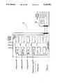
- FIG. 1is a diagrammatic view of a circuit breaker panel configured in accordance with the invention
- FIG. 2depicts a schematic view of a typical tab type series trip circuit breaker with a built-in shunt, as utilized in the circuit breaker panel shown in FIG. 1;
- FIG. 4is a circuit diagram of the power measurement system connected to the circuit breaker panel utilizing the built-in shunt devices of FIGS. 2 and 3;
- FIG. 5is a schematic view of a circuit breaker having a built-in Hall effect sensor usable in the circuit breaker panel illustrated in FIG. 1;
- FIG. 6is a circuit diagram of the measurement system used in conjunction with the built-in Hall effect sensor and circuit breaker of FIG. 5.
- the inventionpertains to an electrical load monitoring system for industrial or commercial buildings, wherein the monitoring apparatus is integrated with the circuit breaker panel.
- the monitoring apparatusis integrated with the circuit breaker panel.
- Each circuit breaker in each panelsupplies current for a particular end use, and all the end use power loads are recorded and summed by a peripheral microprocessing unit.
- the circuit breaker panel 10comprises a series of circuit breaker switches 11a, 11b, 11c, 11d, 11e, etc., respectively, that have been color coded logically, for the convenience of installers, to reflect their end use.
- circuit breaker switch 11ais color coded red, and is connected to the heating circuit of the building.
- Circuit breaker switch 11bis color coded yellow, and switches current to the lighting circuit of the building.
- the various circuit breaker switches 11a, 11b, 11c, etc.connect to different end use circuits supplying particular services within the building.
- Each circuit breaker switch 11a, 11b, 11c, etc., respectively,contains a built-in, current shunt device 12, as shown in the two types of circuit breaker 20 and 20', respectively illustrated in FIGS. 2 and 3.
- Current being drawn through the shunt 12 of either circuit breaker 20 or 20' to feed an end use circuitproduces a voltage that is proportional to, and in phase with the current.
- the shunts 12are sized to provide a full scale voltage in the approximate range of between 0 and 333 mV. This voltage range can be used in breakers carrying 15 amps or 200 amps.
- the necessary resistance of each shuntcan be calculated by dividing the voltage requirement by the current. For example, the shunt resistance for a 200 ampere circuit will be approximately 0.0222 ohms, while the resistance for a 15 ampere circuit will be approximately 0.00166 ohms.
- Each shunted circuit breaker switch 11a, 11b, 11c, etc.has two voltage leads 13a and 13b, respectively. These leads provide a voltage signal proportional to, and in phase with, the current through shunt 12. The leads are connected to a measurement circuit 30, shown in the block diagram adjacent panel 10 of FIG. 1, and in detail in FIG. 4.
- the voltage signals from each pair of voltage leads 13a and 13b, respectively,are multiplexed and fed to small aperture, sample and hold circuits 14 connected to a twelve bit analog to digital converter 15.
- the current signal from each circuit breakeris multiplexed and fed to sample and hold circuits 14' connected to digital converter 15'.
- a microprocessor 16receives the converted signals, sampling the voltage and current wave up to ten times per line cycle.
- the microprocessor 16contains memory for recording the results of each measurement, which is processed into kW or integrated into kW/hr values. All the values for the lighting circuits or for the heating circuits, etc., can be summed to provide a total end use reading.
- circuit breaker 20"featuring a built-in Hall effect sensor 18, is illustrated.
- the circuit breaker 20"can be utilized in the circuit breaker panel 10 of FIG. 1 in place of the shunted circuit breakers 20 and 20' of FIGS. 2 and 3, respectively.
- Hall effect sensor 18 and the associated processing circuitry 40 shown in FIG. 6is housed within the circuit breaker 20'.
- Hall effect devicessuch as Model BH-200 series, and FH-300 series, manufactured by F. W. Bell can be employed in the AC watt measurement.
- Hall sensor 18supplies a bias voltage directly related to the line voltage source from which the current is flowing to the end use circuitry. The voltages are disposed on opposite plate edges A--A and B--B. The operation of the Hall effect device 18 and its plate output voltage is described in U.S. Pat. No. 2,550,492.
- Hall effect plate 19is mounted in the air gap of a current transformer or yoke, through which a current carrying conductor passes.
- Circuit 40depicts similar sample and hold, A/D converter, and microprocessor, as that of circuit 30, shown in FIG. 4.
Landscapes
- Engineering & Computer Science (AREA)
- Power Engineering (AREA)
- Computer Networks & Wireless Communication (AREA)
- Physics & Mathematics (AREA)
- General Physics & Mathematics (AREA)
- Measurement Of Current Or Voltage (AREA)
Abstract
Description
The invention relates to a method and system for monitoring power consumption in a building or other facility, and more particularly to a power consumption monitor that is non-intrusive and forms an integral part of the circuit breaker panels of an industrial or commercial building.
A need presently exists for an inexpensive, non-intrusive means of monitoring power consumption by end use, in an industrial or commercial building. Measurement of peak electrical demand for lighting, heating, cooling and air distribution in a building is useful for both research and billing purposes.
As early as 1953, as disclosed in U.S. Pat. No. 2,654,068 issued to Mertens, entitled "Combined Fuse and Demand Meter," demand (current) meters were disposed in a housed fuse construction, and mounted on the door thereof. Those prior systems, however, provided an indicator only; no provision was made for recording or analyzing data either concurrently or subsequently, nor was an end use application anticipated.
A non-intrusive load monitoring system has been developed for monitoring appliances in private residences, as illustrated and described in U.S. Pat. No. 4,858,141 issued to Hart et al, on Aug. 15, 1989, entitled "Non-intrusive Appliance Monitor Apparatus." The above-mentioned system utilizes harmonics to sense individual devices within a residence from the main meter. This system is generally expensive, despite the fact that it attempts to reduce cost by using sophisticated software in lieu of hardware.
One of the major drawbacks of this prior system is its inability to work effectively with multi-state or variable speed devices, albeit it was never designed to do so. The operational dependence of the aforementioned system upon individual device characteristics makes it impractical for monitoring commercial structures. This is so because commercial buildings have a wider variety of devices, which would require site specific customization. The cost alone of surveying a building for such customization would be prohibitively high. Also, the building industry is currently attempting to eliminate devices that result in disturbances through the electrical system. This would eliminate the ability of the aforesaid system to detect many of the power consuming units.
The present invention seeks to provide an inexpensive, non-intrusive system for monitoring power consumption by end use rather than by identifying a particular device. The invention is incorporated in the circuit breaker panels of commercial buildings, either by retrofit or as original equipment. Of course, economies of installation are achieved by incorporating power measurement into an existing building component (i.e., the circuit breaker), when possible, rather than designing a system having new components which must be interfaced with existing building systems.
The power consumed in any circuit is dedicated to a particular end function, such as lighting or cooling, etc. The measurement of any particular power drain is transmitted to a multiple end use register, where it is summed with similar measurements from other end use sources. Power consumption measurement can be integrated to provide both kW and kW/hr use.
In accordance with the present invention, there is provided a method and system incorporating an integral power consumption monitor-circuit breaker panel for industrial or commercial buildings and facilities. The power consumption monitor-circuit breaker panel not only protects each end use within the building against harmful overloads, but also monitors peak power demands of each end use. Electrical current, voltage and phase information is provided by each monitor-breaker. This information is then fed to a processing circuit that provides a power consumption value. The power consumption value is then fed to recording device to provide a power consumption history for each end use. Each monitor-breaker is identified by its end use, as for example, by color coding. The monitor device of each circuit breaker is designed to provide a voltage that is proportional to the circuit load. Two methods may be used to provide such a voltage signal: a) the voltage signal can be developed across a built-in shunt in each circuit breaker, as it distributes current to its load, the voltage being both proportional to, and in phase with, the current drawn by the load; and b) a proportional voltage can be obtained by use of a circuit breaker with a built-in Hall effect device, wherein the product of the instantaneous current and voltage along with the phase angle between them, provides the power measurement. The current and/or instantaneous power information can be sent to the recording device via a powerline carrier, radio link, or optical fiber. The information can be integrated to provide either kW or kW/hr readings.
A complete understanding of the present invention may be obtained by reference to the accompanying drawings, when considered in conjunction with the subsequent detailed description, in which:
FIG. 1 is a diagrammatic view of a circuit breaker panel configured in accordance with the invention;
FIG. 2 depicts a schematic view of a typical tab type series trip circuit breaker with a built-in shunt, as utilized in the circuit breaker panel shown in FIG. 1;
FIG. 3 is a schematic view of an alternate embodiment of a circuit breaker with built-in shunt, as illustrated in FIG. 2;
FIG. 4 is a circuit diagram of the power measurement system connected to the circuit breaker panel utilizing the built-in shunt devices of FIGS. 2 and 3;
FIG. 5 is a schematic view of a circuit breaker having a built-in Hall effect sensor usable in the circuit breaker panel illustrated in FIG. 1; and
FIG. 6 is a circuit diagram of the measurement system used in conjunction with the built-in Hall effect sensor and circuit breaker of FIG. 5.
Generally speaking, the invention pertains to an electrical load monitoring system for industrial or commercial buildings, wherein the monitoring apparatus is integrated with the circuit breaker panel. Each circuit breaker in each panel supplies current for a particular end use, and all the end use power loads are recorded and summed by a peripheral microprocessing unit.
Now referring to FIG. 1, a typicalcircuit breaker panel 10 is shown in accordance with the present invention. Thecircuit breaker panel 10 comprises a series ofcircuit breaker switches circuit breaker switch 11a is color coded red, and is connected to the heating circuit of the building.Circuit breaker switch 11b is color coded yellow, and switches current to the lighting circuit of the building. The various circuit breaker switches 11a, 11b, 11c, etc., connect to different end use circuits supplying particular services within the building. There may be more than onepanel 10 for large office buildings, in which case there may be apanel 10 with alighting circuit switch 11a for each floor. If an entire panel is dedicated to one end use, power measurement need be made only at the main breaker(s) for the panel.
Eachcircuit breaker switch current shunt device 12, as shown in the two types ofcircuit breaker 20 and 20', respectively illustrated in FIGS. 2 and 3. Current being drawn through theshunt 12 of eithercircuit breaker 20 or 20' to feed an end use circuit produces a voltage that is proportional to, and in phase with the current. Theshunts 12 are sized to provide a full scale voltage in the approximate range of between 0 and 333 mV. This voltage range can be used in breakers carrying 15 amps or 200 amps. The necessary resistance of each shunt can be calculated by dividing the voltage requirement by the current. For example, the shunt resistance for a 200 ampere circuit will be approximately 0.0222 ohms, while the resistance for a 15 ampere circuit will be approximately 0.00166 ohms.
Each shuntedcircuit breaker switch shunt 12. The leads are connected to ameasurement circuit 30, shown in the block diagramadjacent panel 10 of FIG. 1, and in detail in FIG. 4.
The voltage signals from each pair of voltage leads 13a and 13b, respectively, are multiplexed and fed to small aperture, sample and holdcircuits 14 connected to a twelve bit analog todigital converter 15. Likewise, the current signal from each circuit breaker is multiplexed and fed to sample and hold circuits 14' connected to digital converter 15'. Amicroprocessor 16 receives the converted signals, sampling the voltage and current wave up to ten times per line cycle. Themicroprocessor 16 contains memory for recording the results of each measurement, which is processed into kW or integrated into kW/hr values. All the values for the lighting circuits or for the heating circuits, etc., can be summed to provide a total end use reading.
Other means of obtaining the kilowatt readings are available, as can be observed from the circuitry described in U.S. Pat. Nos. 3,505,508; 3,522,421; 3,789,201; 4,034,233; 4,059,747; 4,075,699; 4,240,030; 4,241,237; and 4,253,151. The power measurements can be conveyed to a recording system via a hard wire link, radio, power line carrier or optical fiber.
Referring to FIG. 5, acircuit breaker 20" featuring a built-inHall effect sensor 18, is illustrated. Thecircuit breaker 20" can be utilized in thecircuit breaker panel 10 of FIG. 1 in place of the shuntedcircuit breakers 20 and 20' of FIGS. 2 and 3, respectively.
TheHall effect sensor 18 and the associatedprocessing circuitry 40 shown in FIG. 6 is housed within the circuit breaker 20'. Hall effect devices such as Model BH-200 series, and FH-300 series, manufactured by F. W. Bell can be employed in the AC watt measurement.Hall sensor 18 supplies a bias voltage directly related to the line voltage source from which the current is flowing to the end use circuitry. The voltages are disposed on opposite plate edges A--A and B--B. The operation of theHall effect device 18 and its plate output voltage is described in U.S. Pat. No. 2,550,492.Hall effect plate 19 is mounted in the air gap of a current transformer or yoke, through which a current carrying conductor passes. The output signals are fed to acircuit 40, but do not include the voltage potential inputs required for shunt processing circuitry. The voltage signal ofHall effect sensor 18 provides a signal proportional to instantaneous watts.Circuit 40 depicts similar sample and hold, A/D converter, and microprocessor, as that ofcircuit 30, shown in FIG. 4.
Since other modifications and changes varied to fit particular operating requirements and environments will be apparent to those skilled in the art, the invention is not considered limited to the example chosen for purposes of disclosure, and covers all changes and modifications which do not constitute departures from the true spirit and scope of this invention.
Having thus described the current invention, what is desired to be protected by Letters Patent is presented by the subsequently appended claims.
Claims (16)
1. An end use power consumption monitor for industrial or commercial buildings integrally constructed with a circuit breaker, said power consumption monitor disposed in a current carrying line feeding an end use circuit of said industrial or commercial building, said power consumption monitor providing a voltage signal proportional to current being carried by said circuit breaker for said end use circuit, said power consumption monitor operatively connected to a processing circuit for receiving said voltage signal and for processing said voltage signal to provide a power consumption value for said end use circuit, said end use power consumption monitor further including a circuit breaker panel for housing said power consumption monitor integrally constructed with said circuit breaker, and wherein a plurality of power consumption monitors and integral circuit breakers are housed by said circuit breaker panel, each of said plurality of power consumption monitors and integral circuit breakers being operative for a separate end use, and further wherein each end use is coded to identify said end use on said circuit breaker panel.
2. The end use power consumption monitor of claim 1, wherein said power consumption monitor further comprises a shunt disposed in said current carrying line.
3. The end use power consumption monitor of claim 1, wherein said power consumption monitor further comprises a Hall effect sensor disposed in said current carrying line.
4. The end use power consumption monitor of claim 1, wherein said processing circuit comprises a sample and hold circuit for receiving said voltage signal, an A/D converter connected to said sample and hold circuit for converting said voltage signal to a digital value, and a microprocessor connected to said A/D converter for processing said digital value to provide a power consumption value.
5. The end use power consumption monitor of claim 4, wherein said power consumption value is integrated by said microprocessor to provide a power consumption rate value.
6. A method of determining a power consumption value for an end use circuit of a commercial or industrial building, comprising the steps of:
a) feeding a line current through a circuit breaker to an end use circuit disposed in a commercial or industrial building, said circuit breaker being added to reflect a particular end use to which the circuit breaker is servicing;
b) monitoring said line current within said circuit breaker, and obtaining a voltage signal proportional to said line current being fed to said end use circuit; and
c) processing said voltage signal to provide a power consumption value for said end use circuit.
7. The method of claim 6, wherein said processing step (c) further comprises the step of integrating said voltage signal to provide a power consumption rate value.
8. The method of claim 6, wherein said steps (a) through (c) are performed for each of a plurality of end use circuits.
9. The method of claim 6, further comprising the steps of:
d) recording said power consumption value.
10. The method of claim 8, further comprising the steps of:
d) recording each of said power consumption values.
11. The method of claim 6, further comprising the steps of:
d) breaking the line current to said end use circuit when said line current exceeds a circuit breaker limit.
12. The method of claim 8, further comprising the steps of:
d) breaking the line current to any of said end use circuits when its line current exceeds its circuit breaker limit.
13. An end use power consumption monitor system for industrial or commercial buildings integrally constructed with a circuit breaker panel, said power consumption monitor system comprising:
a plurality of circuit breakers each servicing an end use circuit in an industrial or commercial building, and each being coded to reflect said particular end use to which each circuit breaker is servicing;
a circuit breaker panel for housing said plurality of circuit breakers; and
power consumption monitoring means disposed within each of said plurality of circuit breakers housed in said circuit breaker panel for monitoring power consumption of a respective end use circuit of said industrial or commercial building.
14. The end use power consumption monitor system for industrial or commercial buildings in accordance with claim 13, wherein said power consumption monitoring means further comprises means for providing a power consumption value for each end use circuit.
15. The end use power consumption monitor system for industrial or commercial buildings in accordance with claim 14, wherein said power consumption monitoring means further comprises means for recording said power consumption value for each end use circuit.
16. An end use power consumption monitor system for industrial or commercial buildings in accordance with claim 14, wherein said power consumption monitoring means is connected to a recording means by an optical fiber, said recording means recording a power consumption value for each end use circuit.
Priority Applications (1)
| Application Number | Priority Date | Filing Date | Title |
|---|---|---|---|
| US07/749,374US5196982A (en) | 1991-08-23 | 1991-08-23 | Electrical power monitoring system |
Applications Claiming Priority (1)
| Application Number | Priority Date | Filing Date | Title |
|---|---|---|---|
| US07/749,374US5196982A (en) | 1991-08-23 | 1991-08-23 | Electrical power monitoring system |
Publications (1)
| Publication Number | Publication Date |
|---|---|
| US5196982Atrue US5196982A (en) | 1993-03-23 |
Family
ID=25013494
Family Applications (1)
| Application Number | Title | Priority Date | Filing Date |
|---|---|---|---|
| US07/749,374Expired - LifetimeUS5196982A (en) | 1991-08-23 | 1991-08-23 | Electrical power monitoring system |
Country Status (1)
| Country | Link |
|---|---|
| US (1) | US5196982A (en) |
Cited By (43)
| Publication number | Priority date | Publication date | Assignee | Title |
|---|---|---|---|---|
| US5384712A (en)* | 1991-08-15 | 1995-01-24 | Eaton Corporation | Energy monitoring system for a plurality of local stations with snapshot polling from a central station |
| US5483153A (en)* | 1994-03-24 | 1996-01-09 | Massachusetts Institute Of Technology | Transient event detector for use in nonintrusive load monitoring systems |
| US5572438A (en)* | 1995-01-05 | 1996-11-05 | Teco Energy Management Services | Engery management and building automation system |
| US5615075A (en)* | 1995-05-30 | 1997-03-25 | General Electric Company | AC/DC current sensor for a circuit breaker |
| US5924486A (en)* | 1997-10-29 | 1999-07-20 | Tecom, Inc. | Environmental condition control and energy management system and method |
| EP0969286A3 (en)* | 1998-07-03 | 2001-02-28 | Kamstrup A/S | An apparatus for the determination of electrical power and a method of testing or calibrating a plurality of such apparatus |
| US6330516B1 (en) | 2000-03-27 | 2001-12-11 | Power Distribution, Inc. | Branch circuit monitor |
| US6526360B1 (en)* | 1999-01-11 | 2003-02-25 | Fanuc Ltd. | Power consumption display device for machine |
| US6528957B1 (en) | 1999-09-08 | 2003-03-04 | Lutron Electronics, Co., Inc. | Power/energy management control system |
| US20030135339A1 (en)* | 2002-01-17 | 2003-07-17 | Dario Gristina | System for managing resource infrastructure and resource consumption in real time |
| US20040117330A1 (en)* | 2002-03-28 | 2004-06-17 | Ehlers Gregory A. | System and method for controlling usage of a commodity |
| WO2005006363A2 (en) | 2003-07-09 | 2005-01-20 | Isra-Juk Electronics Ltd | System, apparatus and method for detection of electrical faults |
| US20060294224A1 (en)* | 2005-06-27 | 2006-12-28 | Square D Company | Electrical power management system |
| US20070043478A1 (en)* | 2003-07-28 | 2007-02-22 | Ehlers Gregory A | System and method of controlling an HVAC system |
| US7453267B2 (en) | 2005-01-14 | 2008-11-18 | Power Measurement Ltd. | Branch circuit monitor system |
| GB2450426A (en)* | 2007-06-21 | 2008-12-24 | Patrick Caiger-Smith | Circuit breaker electrical power consumption monitoring |
| GB2456125A (en)* | 2007-10-23 | 2009-07-08 | Senical Ltd | Electricity supply monitoring apparatus |
| US20090206059A1 (en)* | 2008-02-19 | 2009-08-20 | Kiko Frederick J | Intelligent circuit breaker apparatus and methods |
| US20100128404A1 (en)* | 2008-11-24 | 2010-05-27 | Square D Company-Schneider Electric | Improper Voltage Detection for Electronic Circuit Breaker |
| US20100127691A1 (en)* | 2008-11-24 | 2010-05-27 | Square D Company - Schneider Electric | Two Pole Circuit Breaker Voltage Monitoring Integration |
| US20100191487A1 (en)* | 2009-01-26 | 2010-07-29 | Geneva Clean Tech Inc. | Energy usage monitoring with remote display and automatic detection of appliance including graphical user interface |
| CN101661057B (en)* | 2009-09-27 | 2011-03-16 | 哈尔滨理工大学 | Device for implementing power measurement based on resistance sampling by linear optocoupler |
| US20110130887A1 (en)* | 2002-03-28 | 2011-06-02 | Ehlers Sr Gregory Allen | Refrigeration monitor unit |
| US20110148202A1 (en)* | 2009-01-26 | 2011-06-23 | Geneva Cleantech Inc. | Methods and apparatus for power factor correction and reduction of distortion in and noise in a power supply delivery network |
| US8560134B1 (en) | 2010-09-10 | 2013-10-15 | Kwangduk Douglas Lee | System and method for electric load recognition from centrally monitored power signal and its application to home energy management |
| GB2512400A (en)* | 2013-03-29 | 2014-10-01 | Empower Energy Systems Ltd | An electrical energy power consumption monitoring device and an energy management system |
| US8872699B2 (en) | 2011-12-15 | 2014-10-28 | National Instruments Corporation | Resampling a signal to perform synchrophasor measurement |
| US9128132B2 (en) | 2011-12-15 | 2015-09-08 | National Instruments Corporation | Resampling a signal to perform power quality and synchrophasor measurement |
| US9188611B2 (en) | 2011-12-15 | 2015-11-17 | National Instruments Corporation | Resampling a signal to perform power quality measurement |
| RU2578269C1 (en)* | 2015-01-30 | 2016-03-27 | Открытое Акционерное Общество "Российские Железные Дороги" | Intelligent monitoring system for electric network of mobile exhibition and lecture complex |
| RU169776U1 (en)* | 2016-07-29 | 2017-04-03 | Общество с ограниченной ответственностью "Чуткий дом" (ООО "Чуткий дом") | Sensor network node for monitoring current and voltage |
| WO2017066658A1 (en) | 2015-10-16 | 2017-04-20 | Massachusetts Institute Of Technology | Non-intrusive monitoring |
| US9679472B2 (en) | 2010-08-30 | 2017-06-13 | Socovar S.E.C. | Energy consumption evaluation system having reduced energy consumption |
| US9885755B2 (en) | 2013-09-26 | 2018-02-06 | Schneider Electric USA, Inc. | Load center monitor with optical waveguide sheet |
| US9945692B2 (en) | 2013-04-29 | 2018-04-17 | Massachusetts Institute Of Technology | Non-intrusive monitoring |
| RU2693012C1 (en)* | 2018-12-17 | 2019-07-01 | Михаил Михайлович Пукемо | System and method for monitoring and controlling electrical devices |
| US10401401B2 (en) | 2014-03-31 | 2019-09-03 | Panoramic Power Ltd. | System and methods thereof for monitoring of energy consumption cycles |
| US10514399B1 (en) | 2017-08-08 | 2019-12-24 | II Donald P. Orofino | Measurement of alternating electric current via electromagnetic dynamic sensor measurements |
| US10615578B2 (en) | 2016-07-29 | 2020-04-07 | Karle Innovations Ltd. | Electrical equipment with additional compartment and wiring to account for temperature limitations of connected conductors |
| CN111740501A (en)* | 2020-07-23 | 2020-10-02 | 国网天津市电力公司 | A sub-metering circuit breaker device based on non-intrusive technology |
| US10983496B1 (en)* | 2020-10-13 | 2021-04-20 | King Abdulaziz University | Apparatus and method for non-intrusive load monitoring aided hybrid high and low frequency approaches |
| US11024474B1 (en)* | 2014-05-06 | 2021-06-01 | Google Llc | Circuit breakers with integrated safety, control, monitoring, and protection features |
| US11831132B2 (en) | 2020-02-28 | 2023-11-28 | GMS Distribution LLC | Color-coding system for use in power distribution |
Citations (5)
| Publication number | Priority date | Publication date | Assignee | Title |
|---|---|---|---|---|
| US2654068A (en)* | 1947-11-01 | 1953-09-29 | Mcgraw Electric Co | Combined fuse and demand meter |
| US4335437A (en)* | 1980-04-15 | 1982-06-15 | Westinghouse Electric Corp. | Circuit interrupter with energy management functions |
| US4476535A (en)* | 1979-06-01 | 1984-10-09 | Loshing Clement T | System for monitoring, transmitting and conditioning of information gathered at selected locations |
| US4819180A (en)* | 1987-02-13 | 1989-04-04 | Dencor Energy Cost Controls, Inc. | Variable-limit demand controller for metering electrical energy |
| US4858141A (en)* | 1986-04-14 | 1989-08-15 | Massachusetts Institute Of Technology | Non-intrusive appliance monitor apparatus |
- 1991
- 1991-08-23USUS07/749,374patent/US5196982A/ennot_activeExpired - Lifetime
Patent Citations (5)
| Publication number | Priority date | Publication date | Assignee | Title |
|---|---|---|---|---|
| US2654068A (en)* | 1947-11-01 | 1953-09-29 | Mcgraw Electric Co | Combined fuse and demand meter |
| US4476535A (en)* | 1979-06-01 | 1984-10-09 | Loshing Clement T | System for monitoring, transmitting and conditioning of information gathered at selected locations |
| US4335437A (en)* | 1980-04-15 | 1982-06-15 | Westinghouse Electric Corp. | Circuit interrupter with energy management functions |
| US4858141A (en)* | 1986-04-14 | 1989-08-15 | Massachusetts Institute Of Technology | Non-intrusive appliance monitor apparatus |
| US4819180A (en)* | 1987-02-13 | 1989-04-04 | Dencor Energy Cost Controls, Inc. | Variable-limit demand controller for metering electrical energy |
Cited By (67)
| Publication number | Priority date | Publication date | Assignee | Title |
|---|---|---|---|---|
| US5384712A (en)* | 1991-08-15 | 1995-01-24 | Eaton Corporation | Energy monitoring system for a plurality of local stations with snapshot polling from a central station |
| US5420799A (en)* | 1991-08-15 | 1995-05-30 | Eaton Corporation | Circuit breaker - associated backpack unit for lower-link communication with a PC computer monitoring system and energy monitoring system using a plurality of such backpack units |
| US5483153A (en)* | 1994-03-24 | 1996-01-09 | Massachusetts Institute Of Technology | Transient event detector for use in nonintrusive load monitoring systems |
| US5696695A (en)* | 1995-01-05 | 1997-12-09 | Tecom Inc. | System for rate-related control of electrical loads |
| US5684710A (en)* | 1995-01-05 | 1997-11-04 | Tecom Inc. | System for measuring electrical power interruptions |
| US5572438A (en)* | 1995-01-05 | 1996-11-05 | Teco Energy Management Services | Engery management and building automation system |
| US5615075A (en)* | 1995-05-30 | 1997-03-25 | General Electric Company | AC/DC current sensor for a circuit breaker |
| US5924486A (en)* | 1997-10-29 | 1999-07-20 | Tecom, Inc. | Environmental condition control and energy management system and method |
| US6216956B1 (en) | 1997-10-29 | 2001-04-17 | Tocom, Inc. | Environmental condition control and energy management system and method |
| EP0969286A3 (en)* | 1998-07-03 | 2001-02-28 | Kamstrup A/S | An apparatus for the determination of electrical power and a method of testing or calibrating a plurality of such apparatus |
| US6526360B1 (en)* | 1999-01-11 | 2003-02-25 | Fanuc Ltd. | Power consumption display device for machine |
| US6528957B1 (en) | 1999-09-08 | 2003-03-04 | Lutron Electronics, Co., Inc. | Power/energy management control system |
| US6330516B1 (en) | 2000-03-27 | 2001-12-11 | Power Distribution, Inc. | Branch circuit monitor |
| US7069161B2 (en) | 2002-01-17 | 2006-06-27 | Gristina Family Trust | System for managing resource infrastructure and resource consumption in real time |
| US20030135339A1 (en)* | 2002-01-17 | 2003-07-17 | Dario Gristina | System for managing resource infrastructure and resource consumption in real time |
| US20040138981A1 (en)* | 2002-03-28 | 2004-07-15 | Ehlers Gregory A | System and method of controlling delivery and/or usage of a commodity |
| US7343226B2 (en) | 2002-03-28 | 2008-03-11 | Robertshaw Controls Company | System and method of controlling an HVAC system |
| US20040139038A1 (en)* | 2002-03-28 | 2004-07-15 | Ehlers Gregory A. | System and method for controlling delivering of a commodity |
| US7516106B2 (en) | 2002-03-28 | 2009-04-07 | Robert Shaw Controls Company | System and method for controlling usage of a commodity |
| US20050033707A1 (en)* | 2002-03-28 | 2005-02-10 | Ehlers Gregory A. | Configurable architecture for controlling delivery and/or usage of a commodity |
| US20110130887A1 (en)* | 2002-03-28 | 2011-06-02 | Ehlers Sr Gregory Allen | Refrigeration monitor unit |
| US20040133314A1 (en)* | 2002-03-28 | 2004-07-08 | Ehlers Gregory A. | System and method of controlling an HVAC system |
| US7130719B2 (en) | 2002-03-28 | 2006-10-31 | Robertshaw Controls Company | System and method of controlling an HVAC system |
| US20040117330A1 (en)* | 2002-03-28 | 2004-06-17 | Ehlers Gregory A. | System and method for controlling usage of a commodity |
| US7418428B2 (en) | 2002-03-28 | 2008-08-26 | Robertshaw Controls Company | System and method for controlling delivering of a commodity |
| US20070043477A1 (en)* | 2002-03-28 | 2007-02-22 | Ehlers Gregory A | System and method of controlling an HVAC system |
| US7379997B2 (en) | 2002-03-28 | 2008-05-27 | Robertshaw Controls Company | System and method of controlling delivery and/or usage of a commodity |
| US20060119368A1 (en)* | 2003-07-09 | 2006-06-08 | Isaac Sela | System, apparatus and method for detection of electrical faults |
| US7282921B2 (en) | 2003-07-09 | 2007-10-16 | Isra-Juk Electronics Ltd. | System, apparatus and method for detection of electrical faults |
| WO2005006363A2 (en) | 2003-07-09 | 2005-01-20 | Isra-Juk Electronics Ltd | System, apparatus and method for detection of electrical faults |
| US20070043478A1 (en)* | 2003-07-28 | 2007-02-22 | Ehlers Gregory A | System and method of controlling an HVAC system |
| US7453267B2 (en) | 2005-01-14 | 2008-11-18 | Power Measurement Ltd. | Branch circuit monitor system |
| US20060294224A1 (en)* | 2005-06-27 | 2006-12-28 | Square D Company | Electrical power management system |
| GB2450426A (en)* | 2007-06-21 | 2008-12-24 | Patrick Caiger-Smith | Circuit breaker electrical power consumption monitoring |
| GB2456125A (en)* | 2007-10-23 | 2009-07-08 | Senical Ltd | Electricity supply monitoring apparatus |
| US8773827B2 (en) | 2008-02-19 | 2014-07-08 | Simply Automated Incorporated | Intelligent circuit breaker apparatus and methods |
| US20090206059A1 (en)* | 2008-02-19 | 2009-08-20 | Kiko Frederick J | Intelligent circuit breaker apparatus and methods |
| US8106670B2 (en) | 2008-11-24 | 2012-01-31 | Schneider Electric USA, Inc. | Two pole circuit breaker voltage monitoring integration |
| US20100128404A1 (en)* | 2008-11-24 | 2010-05-27 | Square D Company-Schneider Electric | Improper Voltage Detection for Electronic Circuit Breaker |
| US20100127691A1 (en)* | 2008-11-24 | 2010-05-27 | Square D Company - Schneider Electric | Two Pole Circuit Breaker Voltage Monitoring Integration |
| US8649143B2 (en) | 2008-11-24 | 2014-02-11 | Schneider Electric USA, Inc. | Improper voltage detection for electronic circuit breaker |
| US20110148202A1 (en)* | 2009-01-26 | 2011-06-23 | Geneva Cleantech Inc. | Methods and apparatus for power factor correction and reduction of distortion in and noise in a power supply delivery network |
| US8447541B2 (en) | 2009-01-26 | 2013-05-21 | Geneva Cleantech Inc. | Energy usage monitoring with remote display and automatic detection of appliance including graphical user interface |
| US8674544B2 (en) | 2009-01-26 | 2014-03-18 | Geneva Cleantech, Inc. | Methods and apparatus for power factor correction and reduction of distortion in and noise in a power supply delivery network |
| US20100191487A1 (en)* | 2009-01-26 | 2010-07-29 | Geneva Clean Tech Inc. | Energy usage monitoring with remote display and automatic detection of appliance including graphical user interface |
| CN101661057B (en)* | 2009-09-27 | 2011-03-16 | 哈尔滨理工大学 | Device for implementing power measurement based on resistance sampling by linear optocoupler |
| US9679472B2 (en) | 2010-08-30 | 2017-06-13 | Socovar S.E.C. | Energy consumption evaluation system having reduced energy consumption |
| US8560134B1 (en) | 2010-09-10 | 2013-10-15 | Kwangduk Douglas Lee | System and method for electric load recognition from centrally monitored power signal and its application to home energy management |
| US9188611B2 (en) | 2011-12-15 | 2015-11-17 | National Instruments Corporation | Resampling a signal to perform power quality measurement |
| US8872699B2 (en) | 2011-12-15 | 2014-10-28 | National Instruments Corporation | Resampling a signal to perform synchrophasor measurement |
| US9128132B2 (en) | 2011-12-15 | 2015-09-08 | National Instruments Corporation | Resampling a signal to perform power quality and synchrophasor measurement |
| GB2512400A (en)* | 2013-03-29 | 2014-10-01 | Empower Energy Systems Ltd | An electrical energy power consumption monitoring device and an energy management system |
| US9945692B2 (en) | 2013-04-29 | 2018-04-17 | Massachusetts Institute Of Technology | Non-intrusive monitoring |
| US9885755B2 (en) | 2013-09-26 | 2018-02-06 | Schneider Electric USA, Inc. | Load center monitor with optical waveguide sheet |
| US10401401B2 (en) | 2014-03-31 | 2019-09-03 | Panoramic Power Ltd. | System and methods thereof for monitoring of energy consumption cycles |
| US11024474B1 (en)* | 2014-05-06 | 2021-06-01 | Google Llc | Circuit breakers with integrated safety, control, monitoring, and protection features |
| RU2578269C1 (en)* | 2015-01-30 | 2016-03-27 | Открытое Акционерное Общество "Российские Железные Дороги" | Intelligent monitoring system for electric network of mobile exhibition and lecture complex |
| WO2017066658A1 (en) | 2015-10-16 | 2017-04-20 | Massachusetts Institute Of Technology | Non-intrusive monitoring |
| RU169776U1 (en)* | 2016-07-29 | 2017-04-03 | Общество с ограниченной ответственностью "Чуткий дом" (ООО "Чуткий дом") | Sensor network node for monitoring current and voltage |
| US10615578B2 (en) | 2016-07-29 | 2020-04-07 | Karle Innovations Ltd. | Electrical equipment with additional compartment and wiring to account for temperature limitations of connected conductors |
| US12155182B2 (en) | 2016-07-29 | 2024-11-26 | Karle Patents Inc. | Electrical equipment with additional compartment and wiring to account for temperature limitations of connected conductors |
| US10514399B1 (en) | 2017-08-08 | 2019-12-24 | II Donald P. Orofino | Measurement of alternating electric current via electromagnetic dynamic sensor measurements |
| RU2693012C1 (en)* | 2018-12-17 | 2019-07-01 | Михаил Михайлович Пукемо | System and method for monitoring and controlling electrical devices |
| WO2020130885A1 (en)* | 2018-12-17 | 2020-06-25 | Михаил Михайлович ПУКЕМО | System and method for monitoring and controlling electrical devices |
| US11831132B2 (en) | 2020-02-28 | 2023-11-28 | GMS Distribution LLC | Color-coding system for use in power distribution |
| CN111740501A (en)* | 2020-07-23 | 2020-10-02 | 国网天津市电力公司 | A sub-metering circuit breaker device based on non-intrusive technology |
| US10983496B1 (en)* | 2020-10-13 | 2021-04-20 | King Abdulaziz University | Apparatus and method for non-intrusive load monitoring aided hybrid high and low frequency approaches |
Similar Documents
| Publication | Publication Date | Title |
|---|---|---|
| US5196982A (en) | Electrical power monitoring system | |
| EP3367111A1 (en) | Energy metering system | |
| EP1397693B1 (en) | Measuring devices | |
| US6373238B2 (en) | Three-phase electrical power measurement system including three transformers and a measurement circuit to calculate the power thereof | |
| US5995911A (en) | Digital sensor apparatus and system for protection, control, and management of electricity distribution systems | |
| US7330022B2 (en) | Power monitoring system | |
| US7474088B2 (en) | Power monitoring system | |
| US8502688B2 (en) | Standalone self-supplied numeric controlled relay | |
| AU2002310615A1 (en) | Measuring devices | |
| US9310397B2 (en) | Multi-branch current/voltage sensor array | |
| WO1999046606A2 (en) | Electrical power metering system | |
| JP2009273264A (en) | Breaker unit | |
| JP2003222645A (en) | Multi-circuit power measurement device | |
| JP3603876B2 (en) | Weighing device | |
| US3982181A (en) | Apparatus and method for tracing energized AC circuits | |
| EP1459082B1 (en) | A method for on-line calibration of low accuracy voltage sensor through communication bus | |
| KR20000006898A (en) | Electronic Watt-hour Meter with Power Load Control Function | |
| US7336065B1 (en) | Energy device with an extended dynamic range on current readings | |
| KR0123459B1 (en) | Remote monitoring and control device for male and distribution lines | |
| RU2234707C1 (en) | Device for measuring electrical energy with protection from thefts | |
| JP3495194B2 (en) | Control device for received power | |
| Tobin et al. | Remote current sensing on overhead power lines | |
| WO2003008983A2 (en) | Energy consumption control unit | |
| JP2000009757A (en) | Demand monitoring device | |
| GB2379992A (en) | Improvements in or relating to Electricity Meters |
Legal Events
| Date | Code | Title | Description |
|---|---|---|---|
| AS | Assignment | Owner name:FLEMING GROUP, THE, NEW YORK Free format text:ASSIGNMENT OF ASSIGNORS INTEREST.;ASSIGNORS:LANDSBERG, DENNIS;HESSE, BRADLEY J.;REEL/FRAME:005823/0949 Effective date:19910819 | |
| STCF | Information on status: patent grant | Free format text:PATENTED CASE | |
| AS | Assignment | Owner name:SCIENCE APPLICATIONS INTERNATIONAL CORPORATION, CA Free format text:ASSIGNMENT OF ASSIGNORS INTEREST;ASSIGNOR:FLEMING GROUP, THE (A CORP. OF NEW YORK);REEL/FRAME:007186/0090 Effective date:19940926 | |
| FEPP | Fee payment procedure | Free format text:PAT HLDR NO LONGER CLAIMS SMALL ENT STAT AS SMALL BUSINESS (ORIGINAL EVENT CODE: LSM2); ENTITY STATUS OF PATENT OWNER: LARGE ENTITY Free format text:PAYOR NUMBER ASSIGNED (ORIGINAL EVENT CODE: ASPN); ENTITY STATUS OF PATENT OWNER: LARGE ENTITY | |
| REMI | Maintenance fee reminder mailed | ||
| FPAY | Fee payment | Year of fee payment:4 | |
| SULP | Surcharge for late payment | ||
| FPAY | Fee payment | Year of fee payment:8 | |
| FPAY | Fee payment | Year of fee payment:12 |