US5196906A - Modular scatterometer with interchangeable scanning heads - Google Patents
Modular scatterometer with interchangeable scanning headsDownload PDFInfo
- Publication number
- US5196906A US5196906AUS07/547,468US54746890AUS5196906AUS 5196906 AUS5196906 AUS 5196906AUS 54746890 AUS54746890 AUS 54746890AUS 5196906 AUS5196906 AUS 5196906A
- Authority
- US
- United States
- Prior art keywords
- base unit
- scanning head
- scatterometer
- light
- modular
- Prior art date
- Legal status (The legal status is an assumption and is not a legal conclusion. Google has not performed a legal analysis and makes no representation as to the accuracy of the status listed.)
- Expired - Lifetime
Links
- 238000005259measurementMethods0.000claimsabstractdescription75
- 230000002457bidirectional effectEffects0.000claimsabstractdescription7
- 238000005315distribution functionMethods0.000claimsabstractdescription7
- 230000006870functionEffects0.000claimsdescription17
- 238000006243chemical reactionMethods0.000claimsdescription6
- 238000012545processingMethods0.000claimsdescription3
- 230000005540biological transmissionEffects0.000claims6
- 230000003287optical effectEffects0.000abstractdescription22
- 238000000034methodMethods0.000abstractdescription6
- 230000007613environmental effectEffects0.000abstractdescription5
- 238000013500data storageMethods0.000abstract1
- 238000011160researchMethods0.000description11
- 238000012546transferMethods0.000description11
- 238000010586diagramMethods0.000description8
- 239000004065semiconductorSubstances0.000description8
- 230000003068static effectEffects0.000description6
- 238000012360testing methodMethods0.000description4
- 238000004458analytical methodMethods0.000description3
- 238000004364calculation methodMethods0.000description3
- 230000007547defectEffects0.000description3
- 230000003746surface roughnessEffects0.000description3
- XUIMIQQOPSSXEZ-UHFFFAOYSA-NSiliconChemical compound[Si]XUIMIQQOPSSXEZ-UHFFFAOYSA-N0.000description2
- 230000003321amplificationEffects0.000description2
- 238000004891communicationMethods0.000description2
- 238000011109contaminationMethods0.000description2
- 238000007405data analysisMethods0.000description2
- 239000004973liquid crystal related substanceSubstances0.000description2
- 239000000463materialSubstances0.000description2
- 238000003199nucleic acid amplification methodMethods0.000description2
- 230000008569processEffects0.000description2
- 230000001105regulatory effectEffects0.000description2
- 229910052710siliconInorganic materials0.000description2
- 239000010703siliconSubstances0.000description2
- 230000009471actionEffects0.000description1
- 229910052782aluminiumInorganic materials0.000description1
- XAGFODPZIPBFFR-UHFFFAOYSA-NaluminiumChemical compound[Al]XAGFODPZIPBFFR-UHFFFAOYSA-N0.000description1
- 230000000712assemblyEffects0.000description1
- 238000000429assemblyMethods0.000description1
- 230000008859changeEffects0.000description1
- 239000004020conductorSubstances0.000description1
- 230000001276controlling effectEffects0.000description1
- 239000013078crystalSubstances0.000description1
- 125000004122cyclic groupChemical group0.000description1
- 238000001514detection methodMethods0.000description1
- 238000002405diagnostic procedureMethods0.000description1
- 230000000694effectsEffects0.000description1
- 230000005670electromagnetic radiationEffects0.000description1
- 238000005516engineering processMethods0.000description1
- 238000001914filtrationMethods0.000description1
- 229910052732germaniumInorganic materials0.000description1
- GNPVGFCGXDBREM-UHFFFAOYSA-Ngermanium atomChemical compound[Ge]GNPVGFCGXDBREM-UHFFFAOYSA-N0.000description1
- WPYVAWXEWQSOGY-UHFFFAOYSA-Nindium antimonideChemical compound[Sb]#[In]WPYVAWXEWQSOGY-UHFFFAOYSA-N0.000description1
- 230000000977initiatory effectEffects0.000description1
- 238000007689inspectionMethods0.000description1
- XJIHHCVBCQLUNJ-UHFFFAOYSA-Nmanganese mercuryChemical compound[Mn].[Hg]XJIHHCVBCQLUNJ-UHFFFAOYSA-N0.000description1
- 238000004519manufacturing processMethods0.000description1
- 230000008520organizationEffects0.000description1
- 238000003908quality control methodMethods0.000description1
- 238000005070samplingMethods0.000description1
- 239000007787solidSubstances0.000description1
- 230000003595spectral effectEffects0.000description1
- 238000001228spectrumMethods0.000description1
- 238000003860storageMethods0.000description1
- 239000000758substrateSubstances0.000description1
- 238000010998test methodMethods0.000description1
Images


Classifications
- G—PHYSICS
- G01—MEASURING; TESTING
- G01N—INVESTIGATING OR ANALYSING MATERIALS BY DETERMINING THEIR CHEMICAL OR PHYSICAL PROPERTIES
- G01N21/00—Investigating or analysing materials by the use of optical means, i.e. using sub-millimetre waves, infrared, visible or ultraviolet light
- G01N21/17—Systems in which incident light is modified in accordance with the properties of the material investigated
- G01N21/47—Scattering, i.e. diffuse reflection
- G01N21/4738—Diffuse reflection, e.g. also for testing fluids, fibrous materials
- G—PHYSICS
- G01—MEASURING; TESTING
- G01N—INVESTIGATING OR ANALYSING MATERIALS BY DETERMINING THEIR CHEMICAL OR PHYSICAL PROPERTIES
- G01N21/00—Investigating or analysing materials by the use of optical means, i.e. using sub-millimetre waves, infrared, visible or ultraviolet light
- G01N21/01—Arrangements or apparatus for facilitating the optical investigation
- G01N2021/0106—General arrangement of respective parts
- G01N2021/0118—Apparatus with remote processing
- G01N2021/0125—Apparatus with remote processing with stored program or instructions
- G—PHYSICS
- G01—MEASURING; TESTING
- G01N—INVESTIGATING OR ANALYSING MATERIALS BY DETERMINING THEIR CHEMICAL OR PHYSICAL PROPERTIES
- G01N21/00—Investigating or analysing materials by the use of optical means, i.e. using sub-millimetre waves, infrared, visible or ultraviolet light
- G01N21/01—Arrangements or apparatus for facilitating the optical investigation
- G01N2021/0106—General arrangement of respective parts
- G01N2021/0118—Apparatus with remote processing
- G01N2021/0137—Apparatus with remote processing with PC or the like
- G—PHYSICS
- G01—MEASURING; TESTING
- G01N—INVESTIGATING OR ANALYSING MATERIALS BY DETERMINING THEIR CHEMICAL OR PHYSICAL PROPERTIES
- G01N21/00—Investigating or analysing materials by the use of optical means, i.e. using sub-millimetre waves, infrared, visible or ultraviolet light
- G01N21/01—Arrangements or apparatus for facilitating the optical investigation
- G01N2021/0106—General arrangement of respective parts
- G01N2021/015—Apparatus with interchangeable optical heads or interchangeable block of optics and detector
- G—PHYSICS
- G01—MEASURING; TESTING
- G01N—INVESTIGATING OR ANALYSING MATERIALS BY DETERMINING THEIR CHEMICAL OR PHYSICAL PROPERTIES
- G01N21/00—Investigating or analysing materials by the use of optical means, i.e. using sub-millimetre waves, infrared, visible or ultraviolet light
- G01N21/84—Systems specially adapted for particular applications
- G01N21/88—Investigating the presence of flaws or contamination
- G01N21/95—Investigating the presence of flaws or contamination characterised by the material or shape of the object to be examined
- G—PHYSICS
- G01—MEASURING; TESTING
- G01N—INVESTIGATING OR ANALYSING MATERIALS BY DETERMINING THEIR CHEMICAL OR PHYSICAL PROPERTIES
- G01N2201/00—Features of devices classified in G01N21/00
- G01N2201/12—Circuits of general importance; Signal processing
- G01N2201/126—Microprocessor processing
- G01N2201/1266—Interface card
Definitions
- This inventionrelates generally to the field of optical measurement devices. More particularly, the present invention relates to a scatterometer for measuring the amount of light scattered from a sample surface and/or bulk, and then analyzing this information to provide optical performance information, surface roughness statistics, contamination levels, and defect characteristics.
- the optical research measurement devicesare large, relatively expensive apparatus having measurement volumes that exceed several cubic feet and costing between $50,000 to $500,000. These devices are usually permanently mounted on an optical table and employ computer controlled mechanical stages for measuring the reflected light from the sample. Because of the precise nature of the measurements, these type of apparatus require careful alignment and may take several hours to complete an entire set of measurements for a sample.
- the data measured using an optical research measurement deviceis generally presented in a nationally recognized format referred to as the Bidirectional Reflectance Distribution Function (BRDF).
- BRDFBidirectional Reflectance Distribution Function
- optical research measurement devicesexamples include a variety of custom built research measurement instruments for use in various industry and government optical laboratories as shown, for example, in U.S. Pat. Nos. 3,771,880, 3,971,956, 4,156,571, 4,360,275 and 4,859,062.
- Several research measurement scatterometersare also available from Breault Research Organization.
- the assignee of the present invention, TMA Technologies, Inc.also provides two types of optical research measurement instruments: the CASITM line of instruments and the QwikScanTM line of instruments.
- semiconductor manufacturershave created optical research measurement devices to determine the surface characteristics of semiconductor substrates, as shown, for example, in U.S. Pat. Nos. 4,097,160, 4,402,163, 4,583,861 and 4,632,561.
- the inexpensive and less accurate field comparison devicesgenerally perform some type of relative comparison whereby the value obtained by the comparison device is compared to a known good sample, rather than determining an absolute measurement of light intensity. Because the data from this type of device is taken in such a manner to make a relatively quick and inexpensive comparison determination, it is not possible to present the data in the BRDF format. Hence, no meaningful data analysis is possible other than the relative comparison determination.
- Examples of these types of field comparison devicesinclude surface quality systems developed to monitor material quality during manufacturing. Generally, such systems employ a scanning beam, and compare the relative signal changes with the signal from a known good sample to indicate the presence of a flaw.
- Examples of field comparison devices that use scattered light as a comparison to test windshieldsinclude a stray light measuring device as described in the SAE Technical Paper by A. Timmermann and G. Gehring, entitled “Field Measurement of Windshield Surface Wear” (September 1986), and U.S. Pat. Nos. 3,771,877 and 4,687,338.
- a variety of reflectometershave also been used as comparison devices for making simple optical comparisons, including U.S. Pat. Nos. 3,473,878, 4,373,819 and 4,552,458 and a paper by R. Hartman entitled “Field Test Method to Determine Window Replacement Criteria for Optical Systems” (May 1984).
- the present inventionprovides an optical measurement device that can produce quality light scatter measurements expressed in BRDF format generated from an accurate, portable, relatively inexpensive scatterometer.
- the scatterometer of the present inventionis also provided with interchangeable scanning heads, each scanning head being equipped with means for storing certain configuration information about the scanning head.
- interchangeable scanning headsallows the present invention to make measurements of light scatter for a wide variety of applications under a variety of environmental conditions and allows direct analysis of results because the measurement data is expressed in BRDF format.
- the scatterometercomprises a base unit and one or more interchangeable scanning heads.
- the base unitincludes a rechargeable battery power supply, a Central Processing Unit (CPU) with associated Liquid Crystal Display (LCD), and an Input/Output Port (IOP) for entering operator information to control the scatterometer and transfer information between the CPU and the currently connected scanning heads.
- the interchangeable scanning headsinclude one or more light sources and associated optics for producing the light beam that will be reflected off the subject sample surface, one or more detector means for measuring the light scatter, and may be configured with a beam dump at the specular angle direction for measuring the intensity of the reflected light beam.
- the term lightincludes electromagnetic radiation from the ultra-violet (UV) to the mid infrared (IR), e.g. wavelengths from 0.25 to 14 microns.
- the preferred embodiment of the interchangeable scanning headsuses laser diodes as the light sources and silicon detectors to measure the scattered light. It will be recognized, however, that a variety of types of light sources and detectors may be used with the present invention. Examples of suitable light sources include external lasers, light emitting diodes (LED) and broadband thermal sources. Detectors that may be used include silicon and germanium photo diodes, pyroelectric detectors, thermo-electrically cooled diodes, such as indium antimonide and mercury manganese telluride, as well as many others. It will also be recognized that the positioning of the light sources and detectors can be modified to obtain various configurations. For example, some scanning heads might use a linear detector array to record the scatter field, whereas other scanning heads might use an area detector array to record the scanning field.
- the interchangeable scanning headsalso include a means for storing certain configuration data that describe the particular characteristics and other set-up parameters of the scanning head.
- These interchangeable scanning headsare operably connected with the base unit via a shielded cable.
- the cableincludes means for transmitting the actual analog voltage signals received by the detector means directly to the microprocessor in the base unit for analog-to-digital conversion and analysis, as well as means for transmitting and receiving digital signals between the interchangeable scanning head and the base unit.
- An objective of the present inventionis to provide an accurate, portable and relatively inexpensive optical measurement device for measuring light scatter that is capable of making accurate, absolute measurements.
- Another objective of the present inventionis to provide an accurate, portable and relatively inexpensive optical measurement device for measuring light scatter that is capable of presenting data in BRDF format and analyzing the data to provide needed sample characteristics.
- a further objective of the present inventionis to provide an optical measurement device capable of making measurements of light scatter for a wide variety of applications under a variety of environmental conditions.
- Another objective of the present inventionis to provide a modular scatterometer having interchangeable scanning heads that can be individually adapted for scanning different types of measurement needs.
- Still another objective of the present inventionis to provide a modular scatterometer having interchangeable scanning heads, each scanning head having means for storing information about the head configuration and the sample scatter data.
- a further objective of the present inventionis to provide scatter data in BRDF format so that it can be directly compared to data obtained from expensive, larger research measurement systems.
- a still further objective of the present inventionis to allow for analysis of BRDF data to provide information such as surface roughness and defect characteristics without requiring that reference samples be transported to expensive, non-portable, research measurement instruments.
- FIG. 1is an isometric view of the preferred embodiment of scatterometer of the present invention with an interchangeable scanning head attached to the base unit and also showing additional interchangeable scanning heads.
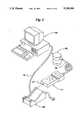
- FIG. 2is an isometric view of an alternative embodiment showing the showing the scatterometer with an attached personal computer (PC).
- PCpersonal computer
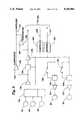
- FIG. 3is a flow diagram of the primary operational functions of the present invention.
- FIG. 4is an electrical block diagram of the base unit showing the interconnections of the major functional components within the base unit.
- FIG. 5is a flow diagram showing the major functions performed by the CPU to insure that one of the interchangeable scanner heads is properly connected and is operable.
- FIG. 6is a flow diagram showing the major functions performed by the CPU during a measurement process.
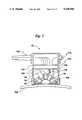
- FIG. 7is a cut-away view of one of the interchangeable scanning head assemblies of FIG. 1.
- FIG. 8is a pictorial view of a larger scanning head in which the sample is placed inside a light shielding box.
- FIG. 9is a block diagram showing the major components of the light source, detectors and other electronics associated with one of the scanning heads for the present invention.
- FIG. 10is a flow diagram showing the operational flow for information transfer between the CPU and a PC.
- FIG. 1shows a pictorial view of the preferred embodiment of the modular, portable handheld scatterometer of the present invention.
- the present inventioncan produce quality direct light scatter measurements expressed in Bidirectional Reflective Distribution Function (BRDF) format on a variety of surfaces utilizing one of a plurality of interchangeable scanning heads.
- BRDFBidirectional Reflective Distribution Function
- the present inventioncan be used to determine both the scattered light level and the RMS roughness on either flat or curved surfaces under most any lighting and environmental conditions. Because the present invention determines a single, direct light measurement for each detector, it will be appreciated that this measurement can be expressed in a variety of ways and still be within the scope of the present invention. For example, instead of expressing the light measurement in terms of BRDF, it would be possible to conversely express the light measurement in terms of BTDF (bidirectional transmissive distribution function), or a combination of both BRDF and BTDF. As such, it will be seen that the present invention is capable of both reflective and transmissive measurements, both in-plane and out-of-plane.
- RMS roughnessmay be calculated over a user specified bandwidth from the BRDF data.
- a base unit 10embodies a central processing unit means or CPU 12 which is controlled by a stored program contained in an EPROM 14.
- the base unit 10also contains a dynamic storage memory 16 which, in the preferred embodiment, has its own internal battery power means 18 to prevent loss of data.
- a multi-keypad 20provides an operator interface means by which to operate the base unit 10.
- the multi-keypad 20includes selectable options that allow for menu selections, entering of data constants, initiation of diagnostics to name some features of the preferred embodiment.
- Alphanumeric informationis presented to the operator by means of a liquid crystal display (LCD) 22.
- LCDliquid crystal display
- Power for the preferred embodiment of the base unit 10is provided by rechargeable batteries 24.
- the rechargeable batteries 24may be recharged when the base unit 10 is placed in a charger stand 26.
- a nine-pin connector 27is the means for transferring charging energy from the charger stand 26 to the rechargeable batteries 24.
- the charging stand 26obtains its electrical energy from standard 120 volt AC, 60 Hz current conducted by power cable 25.
- FIG. 1also shows another version 30 of an interchangeable scanning head in which the sample itself can be placed inside the scanning means. It will be understood that there can be many different types of interchangeable scanning heads having configurations based upon the intended use or application of the present invention. For purposes of describing the preferred embodiment of the present invention three different interchangeable scanning heads 28, 29 and 30 will be described. As shown for scanning head 28, a light source 32 and one or more detectors 34 provide the light and determine the scattering of that light necessary to obtain the desired light measurement data. The amount of scattered light measured by the detector or detectors 34 as power is converted to an analog voltage.
- This analog voltageis amplified and filtered by an electronic interface circuit card 36.
- the selected scanning head 28is connected to the base unit 10 via a universal cable 38.
- the universal cable 38passes information from the electronic interface circuit card 36 to an I/O port (IOP) 42 in the base unit 10.
- the base unit 10also includes means to convert analog voltages received at the IOP 42 to digital format utilizing an A/D converter 40.
- an independent workstation or personal computer (PC) 50is connected to the base unit 10 through a serial data cable 52 connected between the PC 50 and the charger stand 26. Serial data information is thus transferred to the CPU 12 through the charger stand 26 via the data port/charger connector 27.
- This alternate embodimentprovides means to store and retieve data and information from the PC 50 for use in the CPU 12. Also, information in the CPU 12 can be stored in the PC 50.
- data measured by the base unit 10can be compared to other data taken at previous times or to data from other samples. In this way changes in the surface sample being measured can be analyzed over a given time period, for example.
- the PC 50can be provided with any number of available statistical or customized programs to analyze and compare measured or calculated data.
- the CPU 12is a 80C31 available from Intel Corporation of Santa Clara, CA.
- the EPROM 14is a NMC27C512AQ EPROM available from National Semiconductor Corporation of Santa Clara, CA.
- the static RAM 16is a MCM60L256A static RAM available from Motorola Semiconductor Products. Inc. of Austin, TX.
- the battery backup 18 for the static RAM 16is a DS1216C battery backup available from Dallas Semiconductor of Dallas, TX.
- the A/D converter 40is an ADC0808 A/D converter from Texas Instruments of Dallas, TX.
- the I/O port 42is constructed using 74HCT245 and 74HCT273 circuits available from National Semiconductor Corporation of Santa Clara, CA.
- the base unit 10causes messages 54 to be displayed by means of the LCD 22. These messages 54 are displayed whenever the base unit 10 is turned on and provide information about the base unit 10, such as the serial number, available memory status or time since last calibration.
- the second operational functionis system diagnostics 56. Diagnostics are performed to insure that the base unit 10 is operating properly so that no measurement data will be taken if the diagnostics tests 56 fail.
- the diagnostics tests 56include a system voltage to verify nominal system voltages, a memory test of the static RAM 16 and a check of the functionality of the multi-keypad 20.
- the head diagnostic block 58performs diagnostic operations to insure that one of several selectable scanning heads 28, 29, 30 is installed and currently connected to the CPU 12.
- the manner in which the CPU 12 interrogates the currently connected one of the scanning heads 28, 29, 30 as part of the head diagnostic block 58is described in greater detail in connection with the description of FIG. 5. This completes the diagnostic sequence. It will be recognized that these and other diagnostic routines that are well known in the art may be performed as part of the diagnostic test 56 and the head diagnostic block 58.
- Main menu 60 entriesinclude: Take Measurements 61a, Setup 61b and Options 61c.
- the operation of Take Measurements 61ais described in greater detail hereinafter in connection with the description of FIG. 6.
- the Setup option 61ballows the operator to add, delete or change sample labels for the data measurements to be taken.
- Options 61cis the third selectable function in the menu list 60.
- Options 61callows the operator to access the PC 50 through the serial IOP 27 for transferring information to a PC 50, or run diagnostics or obtain a summary of data values previously obtained and stored in the base unit 10.
- FIG. 4shows how major functional components in the base unit 10 are related for information and data transfer.
- Operator controlis provided by the multi-keypad 20 in the preferred embodiment.
- Input selections via the multi-keypad 20are connected to a parallel input/output port (IOP) 42.
- the parallel IOP 42provide means for receiving data from the multi-keypad 20.
- the IOP 42also provides means for transferring information into and out of the base unit 10 from the currently attached scanning head 28 via the universal cable 38.
- Commands from the multi-keypad 20instruct the firmware program located in the EPROM 14 what function is requested by the operator. For example, menu commands may be required to be displayed in the LCD 22.
- the LCD 22is a 20 character by 4 line display, it will be recognized that some applications will require only a single line to just display data or that an alternative embodiment might make use of a graphics display to show BRDF on a continuous graphical basis.
- the multi-keypad 20 functioncan cause data to be read by the currently connected scanning head 28, 29 or 30.
- the analog voltage datawould be present on A/D converter 40 input line on two channels.
- the universal cable 38can transfer a signal from the remote switch on the currently connected scanning head 28, 29 or 30. This switch is electrically in parallel with a similar command from the multi-keypad 20.
- the A/D converter 40has 8 channel capacity with 8 bit accuracy. In the preferred embodiment, only 4 channels are utilized. Two of these utilized channels are used to monitor battery 24 level and regulated supply voltage 62 level. If the rechargeable battery 24 voltage is too low, then the preferred embodiment will not allow scatter readings to be taken, and a diagnostic message is presented and the system automatically powers down.
- the base unit 10 circuitsare operated on a regulated 5 volt supply 62. There are 2 channels from the selected scanning head 28 assembly to the A/D 40. During operation of the data acquisition mode, all signals on the universal cable 38, other than the 2 channels connected to the A/D 40, are quieted to allow for the most precise transfer and conversions of the analog signal levels detected by the selected scanning head 28.
- 8 bit accuracyis sufficient because of the use of linear gain stages in the scanning head electronics 36. It will be recognized, however, that higher accuracy A/D converters 40 may also be used. In addition, it is also possible to place the A/D converter 40 circuit in the interchangeable scanning heads 28, 29, 30, rather than in the base unit 10. Although this configuration would be more expensive, it would make it possible to reduce the number of lines to the selected scanning head 28 and also to transfer data in digital rather than analog form.
- the real time clock 64is used to provide time and date signature for measurements.
- the level converter 66converts the 0-5 v TTL voltage levels to +12 v, -12 v for use in RS232 circuits. All functions are controlled by the micro processor CPU 12.
- FIG. 5illustrates the operational flow of the software for controlling the CPU 12.
- a boot up sequenceis followed to insure the unit is operating correctly and that there is a scanning head 28, 29 or 30 attached.
- Boot-upbegins with initialization 70 of the I/O ports 42. This consists of setting each of the port bits to their default values.
- the next step 72is to determine if one of the interchangeable scanning heads 28, 29 or 30 is connected to the base unit 10. Determination of the connection of a selected one of the scanning heads 28, 29 or 30 is accomplished by means of reading the analog voltage level from the selected scanning head 28. If the voltage is greater than a predetermined value, then a scanning head is not connected. Another method to determine if a scanning head is present would be to examine the bit level of a selected line.
- the next step 74is to read the serial number of the selected scanning head 28. This is done by reading the serial number stored in a scanning head EEPROM 122 (FIG. 9).
- the next step 76is to determine if the selected scanning head 28 is the same as the previous one used. If yes, then the program can continue to obtain data in the manner described in FIG. 6. If a different interchangeable scanning head 29 or 30 has been attached, or if this is the first measurement being taken since the base unit 10 was powered up, then data stored in the scanning head EEPROM 122 must be transferred to the static RAM 16 in the base unit 10 at step 78.
- the data retrieved from the EEPROM 122 during step 78represents information sufficient for mathematically describing the physical characteristics of the particular scanning head 28, 29 or 30. This information includes the physical locations of source 32 and detector 34 mounting locations, as well as calibration constants and other information about optical characteristics of the scanning head 28, 29 or 30 the source 32, and the detector 34.
- Error checking 80is accomplished using a checksum method. Other error checking schemes could also be employed such as cyclic redundancy checks. If the data from the selected scanning head 28 has been transferred successfully, then the boot-up procedure is completed. If a data transfer error occur, then a HEAD ERROR diagnostic is reported on the LCD 22 and the CPU 12 prevents access to measurement features.
- FIG. 6illustrates the software functions that perform the calculation and display of BRDF measurement results.
- Information transferred to the CPU 12 during the boot-up phaseincludes scanning head 28 information such as the number of sources 32 and the number of detectors 34 in the selected attached scanning head 28.
- the preferred embodimentallows for from 1 to 3 light sources 32, and from 1 to 8 detectors 34 to be contained within the scanning head 28.
- the first step 82is to select and turn on the selected light source 32.
- the second step 84is to select and turn on one or more selected detectors 34 in this scanning head 28. Selection and turning on of light sources 32 and detectors 34 is achieved by transferring the proper control word from the base unit 10 to the selected scanning head 28.
- the next step 86is to set the optimal maximum gain of the first detector 34.
- the amount of reflected lightvaries from sample to sample.
- the preferred embodimentutilizes both pre and post linear gain amplification stages. Combinations of these amplifiers allows gains to be set by the base unit 10 from 0 to 80 db in 10 db steps. Another way to obtain amplification is to utilize logarithmic gain stages.
- sampling 88occurs. Samples are taken every T seconds for N seconds where T and N are chosen to minimize the effects of noise. The average 90 of these samples is computed.
- the range of the resulting data samplesare examined to see if they fall within the range of the A/D 40 without clipping.
- the range of the A/D 40means of the preferred embodiment is 1-254.
- the actual BRDF calculation for the selected detector 34are made at step 94 using the information and coefficients previously transferred from the EEPROM 122 in the scanning head 28.
- FIG. 7shows a cut-away view of one of several selectable interchangeable scanning heads 28.
- the selected one of the scanning heads 28, 29 or 30is connected to the base unit 10 by a universal cable 38.
- the universal cable 38consists of 12 conductors with 12 pin male connectors 100 on each end.
- the containing means for this example of the preferred embodimentconsists of a cylindrical aluminum housing 102 which contains the electronics assembly 104, and a non-conducting, opaque detector/source mount 106. As many as three light sources 32 and as many as 8 detectors 34, can be mounted in a selected version of the source mount 106.
- the detector/source mount 106is mounted on springs to the cylinder 102 to allow the operator to precisely position the head on curved surfaced samples 108 to be measured.
- only one source 32is used.
- a typical source 32could be a 670 nm laser diode.
- Other sources 32, such as infrared diodes,are also usable depending upon the desired application.
- Light from the source 32is reflected from the sample surface 108 through the beam dump opening 112 to the beam dump detector 110. Measurements of the beam at the beam dump 110 are taken for reflectance calculations.
- the purpose of beam dumpingis to remove the specular beam from the inner volume of the source/detector housing 106. This allows measurement of only scattered light by removing all purely reflected light.
- Light scattered from the surfaceis measured by one or more detectors 34 placed at locations around the surface of the source/detector mount 106. In this embodiment of the scanning head 28, source 32 and detectors 34 are mounted at 30 degree angle spacing from the vertical for the particular geometry of this unit. Other spacings can be chosen for this or other size scanning head 28. This particular embodiment of scanning head 28 is designed to be hand-held.
- There is a measurement switch 114which can be operated to cause readings to be taken each time the switch is operated.
- FIG. 8is another version of an interchangeable scanning head 30.
- This scanning head 30connects to the base unit 10 via the universal cable 38.
- the function of this scanning head 30is to measure scatter from samples which are placed inside it.
- Detectors 34can be mounted in several positions, and the sample 108 height can be varied by the sample height adjustment 116.
- the remote trigger 114causes measurements to be recorded and transmitted to the base unit 10.
- Electronics boards 104provide the same functions as those described for FIGS. 7 and 9.
- FIG. 9is a block diagram showing the functions performed by electronics boards 104 or electronic interface circuit card 36 located in each of several selectable scanning heads 28, 29, 30 of the present invention. Communications between the base unit 10 and a selected scanning head 28 are handled by the control circuits 120. Configuration information for a selected scanning head 28 is contained in the EEPROM memory 122. Configuration information which includes scanning head serial number and configuration of sources and detectors, is transferred to the base unit 10 via a serial data circuit 121 on the universal cable 38. A second serial data circuit 123 provides transfer of other commands from the base unit 10 to a selected scanning head 28. These commands include "Source On,” “Detector Select,” and “Gain Select.” Commands from the base unit 10 received by a selected scanning head 28 are decoded in the control 120 section by two eight-bit shift registers.
- the command to initiate a scatter measurementis comprised of a sequence of individual control functions.
- a source 32is turned on.
- Each source 32has its own driver 124.
- an operational amplifier driving a bipolar junction transistoris utilized, although it will be recognized that several other devices that can be used to drive these sources.
- the driver circuit 124contains an adjustable regulator, designed to provide constant source 32 output intensity with varying supply voltages levels and to compensate for variations among individual sources 32.
- the modulator 126applies square wave modulation to the driver 124 at about 600 Hz, with a duty cycle of about 50%. The square wave is produced by a mono-stable multi-vibrator. A second output from the modulator 126 is used as a phase reference by the filter section 136.
- the modulator 126also contains a switch 130 to allow the source 32 to be manually operated continuously without modulation for source alignment purposes.
- Direct light from the source 32, or scattered light from the sampleis received by one or more detectors 34.
- the detector 34 that will be used for the measurementis selected by the commands from the base unit 10 as decoded by the control 120 and sent to the multiplexer 132. Unused detectors 34 are shorted and grounded to reduce circuit noise.
- the preferred embodimentutilizes a multiplexer 132, it should be noted that there are other ways to provide for selection of the detector 34.
- each detector 34could have its own amplifier 134, filter 136, and final amplifier 138.
- Analog voltage from the selected detector 34is routed to an amplifier 134.
- the current-sense signal from the detector 34is converted to a voltage-sense signal, and amplified by four cascaded stages of an operational amplifier. The fourth of these stages is configured for two discrete values of gain, controlled by signals from the control 120.
- the filter 136uses a phase reference signal from the modulator 126 section to provide an extremely selective filtering action.
- the filter 136also uses an operational amplifier.
- the gain of the filter 136 sectionis controlled by the base unit 10 command routed to control 120.
- the final amplifier 138uses an operational amplifier. Two discrete values of gain may be selected by a signal from the base unit 10 via a command to control 120. The signal level is sampled at two points in the signal path.
- a comparator 139which provides an overload signal 141 to the base unit 10 if the gain settings are too large. This allows the CPU 12 to set the optimum amount of gain for the received signal.
- the detector 34 output signalis referenced to an analog ground, different in potential from the logic and power supply grounds. This allows a definite value to be defined for zero received signal.
- the EEPROM 122 memoryis a type 24C16I from Xicor, Inc of Milpitas, CA. Shift registers used are 74HC595 such as from National Semiconductor Corporation of Santa Clara, CA.
- the TLC555ID multi-vibrator, TLC2201BID and TLC2654 operational amplifiers and TLC3541D comparatorsare all from Texas Instruments, Inc of Dallas, Tx. Solid state analog switches used are DG403DY available from Siliconix of Santa Clara, CA.
- FIG. 10shows the operational flow for information transfer between the base unit 10 and the PC 50 of the alternate embodiment.
- the first function 140is to use the multi-keypad 20 to obtain access to the serial port menu.
- the next step 142is to initiate base unit 10 to PC 50 communications.
- the PC 50sends as ASCII character to notify the base unit 10 that it is ready for data transfer.
- the next operational function 144is to read the list of measurement sample file names stored in the base unit 10. In the preferred embodiment, there can be as many as 255 files, with as many as 255 measurements stored in each named file.
- Information transfer 146 from the base unit 10 to the PC 50can include base unit 10 unit number, scanning head source and or detector angles, previously saved BRDF measurements, and time/date information. It will be recognized, however, that any information applicable to this or other applications of this embodiment which is stored in the base unit 10 can be transferred to the PC 50. This information can then be analyzed or otherwise used by programs stored in the PC 50.
Landscapes
- Physics & Mathematics (AREA)
- Health & Medical Sciences (AREA)
- Life Sciences & Earth Sciences (AREA)
- Chemical & Material Sciences (AREA)
- Analytical Chemistry (AREA)
- Biochemistry (AREA)
- General Health & Medical Sciences (AREA)
- General Physics & Mathematics (AREA)
- Immunology (AREA)
- Pathology (AREA)
- Investigating Or Analysing Materials By Optical Means (AREA)
Abstract
Description
Claims (19)
Priority Applications (2)
| Application Number | Priority Date | Filing Date | Title |
|---|---|---|---|
| US07/547,468US5196906A (en) | 1990-06-29 | 1990-06-29 | Modular scatterometer with interchangeable scanning heads |
| PCT/US1991/004625WO1992000514A1 (en) | 1990-06-29 | 1991-06-28 | Modular scatterometer with interchangeable scanning heads |
Applications Claiming Priority (1)
| Application Number | Priority Date | Filing Date | Title |
|---|---|---|---|
| US07/547,468US5196906A (en) | 1990-06-29 | 1990-06-29 | Modular scatterometer with interchangeable scanning heads |
Publications (1)
| Publication Number | Publication Date |
|---|---|
| US5196906Atrue US5196906A (en) | 1993-03-23 |
Family
ID=24184744
Family Applications (1)
| Application Number | Title | Priority Date | Filing Date |
|---|---|---|---|
| US07/547,468Expired - LifetimeUS5196906A (en) | 1990-06-29 | 1990-06-29 | Modular scatterometer with interchangeable scanning heads |
Country Status (2)
| Country | Link |
|---|---|
| US (1) | US5196906A (en) |
| WO (1) | WO1992000514A1 (en) |
Cited By (31)
| Publication number | Priority date | Publication date | Assignee | Title |
|---|---|---|---|---|
| US5608527A (en)* | 1995-03-08 | 1997-03-04 | Optical Dimensions, Llc | Apparatus and method for dynamic measurement of surface roughness |
| US5754283A (en)* | 1994-10-26 | 1998-05-19 | Byk-Gardner Usa, Division Of Atlana | Color measuring device having interchangeable optical geometries |
| US5912741A (en)* | 1997-10-10 | 1999-06-15 | Northrop Grumman Corporation | Imaging scatterometer |
| US5963333A (en)* | 1996-09-12 | 1999-10-05 | Color Savvy Systems Limited | Color sensor |
| US6184528B1 (en) | 1998-08-27 | 2001-02-06 | Vought Aircraft Industries, Inc. | Method of spectral nondestructive evaluation |
| US6394105B1 (en)* | 1998-03-19 | 2002-05-28 | Seagate Technology, Inc. | Integrated laser cleaning and inspection system for rigid thin film media for magnetic recording application |
| US20020080357A1 (en)* | 2000-11-15 | 2002-06-27 | Dana Kristin J. | Apparatus and method for measuring spatially varying bidirectional reflectance distribution function |
| US20020145740A1 (en)* | 2001-03-26 | 2002-10-10 | Meeks Steven W. | Material independent optical profilometer |
| US20020163634A1 (en)* | 2001-03-26 | 2002-11-07 | Meeks Steven W. | Multiple spot size optical profilometer, ellipsometer, reflectometer and scatterometer |
| US20030025905A1 (en)* | 2001-03-26 | 2003-02-06 | Meeks Steven W. | Method of detecting and classifying scratches, particles and pits on thin film disks or wafers |
| US20030197874A1 (en)* | 2002-04-19 | 2003-10-23 | Moghaddam Alireza Shahdoost | Method of detecting the thickness of thin film disks or wafers |
| US6665078B1 (en) | 1997-09-22 | 2003-12-16 | Candela Instruments | System and method for simultaneously measuring thin film layer thickness, reflectivity, roughness, surface profile and magnetic pattern in thin film magnetic disks and silicon wafers |
| US20040017561A1 (en)* | 1997-09-22 | 2004-01-29 | Meeks Steven W. | Method of detecting and classifying scratches and particles on thin film disks or wafers |
| US20040051874A1 (en)* | 2001-01-19 | 2004-03-18 | Rudiger Kubitzek | Measuring device |
| US6757056B1 (en) | 2001-03-26 | 2004-06-29 | Candela Instruments | Combined high speed optical profilometer and ellipsometer |
| US20040141175A1 (en)* | 2002-07-12 | 2004-07-22 | Leo Baldwin | Method and apparatus for uniform lighting source |
| GB2398119A (en)* | 2002-10-23 | 2004-08-11 | Saint Gobain | Identifying the presence of a coating on a surface of a glass substrate from successive measurements of light reflected from the surface |
| US20040169850A1 (en)* | 1999-07-02 | 2004-09-02 | Meeks Steven W. | System and method for double sided optical inspection of thin film disks or wafers |
| US6956660B2 (en) | 1997-09-22 | 2005-10-18 | Kla-Tencor Technologies | System and method for measuring properties of an object using a phase difference between two reflected light signals |
| US20050246542A1 (en)* | 2004-04-28 | 2005-11-03 | Rutgers, The State University | Method and apparatus for making and detecting a document verification indicator using optical pattern encryption |
| US7075741B1 (en) | 2004-06-14 | 2006-07-11 | Kla Tencor Technologues Corporation | System and method for automatically determining magnetic eccentricity of a disk |
| US7201799B1 (en) | 2004-11-24 | 2007-04-10 | Kla-Tencor Technologies Corporation | System and method for classifying, detecting, and counting micropipes |
| US20070187505A1 (en)* | 2006-01-23 | 2007-08-16 | Rhoads Geoffrey B | Capturing Physical Feature Data |
| US20080121708A1 (en)* | 2006-11-15 | 2008-05-29 | Rhoads Geoffrey B | Physical Credentials and Related Methods |
| US7396022B1 (en) | 2004-09-28 | 2008-07-08 | Kla-Tencor Technologies Corp. | System and method for optimizing wafer flatness at high rotational speeds |
| US20090079987A1 (en)* | 2007-09-25 | 2009-03-26 | Microsoft Corporation | Photodiode-based Bi-Directional Reflectance Distribution Function (BRDF) Measurement |
| US7684032B1 (en) | 2005-01-06 | 2010-03-23 | Kla-Tencor Corporation | Multi-wavelength system and method for detecting epitaxial layer defects |
| US20110141476A1 (en)* | 2009-12-10 | 2011-06-16 | Palo Alto Research Center Incorporated | Light scattering measurement system based on flexible sensor array |
| WO2012010724A1 (en)* | 2010-07-21 | 2012-01-26 | Abengoa Solar New Technologies S. A. | Portable reflectometer and method for characterising the mirrors of solar thermal power plants |
| US8224018B2 (en) | 2006-01-23 | 2012-07-17 | Digimarc Corporation | Sensing data from physical objects |
| US8582117B2 (en) | 2011-04-08 | 2013-11-12 | Schmitt Industries, Inc. | Systems and methods for calibrating an optical non-contact surface roughness measurement device |
Families Citing this family (2)
| Publication number | Priority date | Publication date | Assignee | Title |
|---|---|---|---|---|
| EP0845668A3 (en)* | 1998-02-20 | 1998-09-02 | Heinz Wagner | Method and apparatus for investigating at least one property of a material |
| CN109342329A (en)* | 2018-10-26 | 2019-02-15 | 长春理工大学 | BRDF automatic test system and test method |
Citations (27)
| Publication number | Priority date | Publication date | Assignee | Title |
|---|---|---|---|---|
| US2830490A (en)* | 1955-09-16 | 1958-04-15 | Mary S Pellegrini | Method and apparatus for measuring the surface smoothness of glossy objects |
| US3327583A (en)* | 1962-07-16 | 1967-06-27 | Lion Res Corp | Apparatus with diffusely reflecting hollow housing for measuring absolute reflectivity of a surface and the like |
| US3421821A (en)* | 1964-12-10 | 1969-01-14 | Patrick A Alessi | Color spectrum analyzer |
| US3473878A (en)* | 1966-11-14 | 1969-10-21 | Welch Scient Co The | Reflection head for measuring diffuse reflection density |
| US3496359A (en)* | 1966-02-09 | 1970-02-17 | Unit Process Assemblies | Portable beta backscatter type measuring instrument |
| US3746869A (en)* | 1970-09-30 | 1973-07-17 | Zeiss Stiftung | Method of photometrically plotting light scattering objects |
| US3771880A (en)* | 1971-09-29 | 1973-11-13 | Us Navy | Roughness analyzer |
| US3971956A (en)* | 1974-01-21 | 1976-07-27 | National Research Development Corporation | Measurement of surface roughness |
| US4072426A (en)* | 1974-01-17 | 1978-02-07 | Pluss-Staufer Ag | Method and apparatus for determining the reflective properties of surfaces, especially coated surfaces |
| US4097160A (en)* | 1974-09-06 | 1978-06-27 | Canon Kabushiki Kaisha | Method for inspecting object defection by light beam |
| US4156571A (en)* | 1977-09-07 | 1979-05-29 | The Singer Company | Laser mirror scatter and reflectivity measuring system |
| US4218144A (en)* | 1977-09-09 | 1980-08-19 | The Rank Organisation Limited | Measuring instruments |
| US4269518A (en)* | 1979-06-18 | 1981-05-26 | The United States Of America As Represented By The Secretary Of The Navy | Stray light eliminator in a scatterometer |
| US4360275A (en)* | 1980-08-11 | 1982-11-23 | Litton Systems Inc. | Device for measurement of optical scattering |
| US4365896A (en)* | 1980-04-03 | 1982-12-28 | Bethlehem Steel Corp. | Optical attenuation monitor system and method |
| US4373819A (en)* | 1979-12-21 | 1983-02-15 | Stefano Pallotta | Retroreflectometer giving direct reading |
| US4402613A (en)* | 1979-03-29 | 1983-09-06 | Advanced Semiconductor Materials America | Surface inspection system |
| US4484819A (en)* | 1982-06-16 | 1984-11-27 | The United States Of America As Represented By The Secretary Of The Navy | Reflectometer |
| US4552458A (en)* | 1983-10-11 | 1985-11-12 | Eastman Kodak Company | Compact reflectometer |
| US4583861A (en)* | 1981-08-12 | 1986-04-22 | Tokyo Shibaura Denki Kabushiki Kaisha | Surface condition judging apparatus |
| US4607955A (en)* | 1984-08-16 | 1986-08-26 | The Electron Machine Corporation | Stock consistency transmitter |
| US4632561A (en)* | 1985-04-30 | 1986-12-30 | Therma-Wave, Inc. | Evaluation of surface and subsurface characteristics of a sample |
| US4687338A (en)* | 1983-02-02 | 1987-08-18 | The United States Of America As Represented By The Secretary Of The Air Force | Method of measurement of haze in transparencies |
| US4750822A (en)* | 1986-03-28 | 1988-06-14 | Therma-Wave, Inc. | Method and apparatus for optically detecting surface states in materials |
| US4761676A (en)* | 1986-08-22 | 1988-08-02 | Ati Systems Inc. | Fault detection and reset in surface reflectance meter |
| US4859062A (en)* | 1980-10-04 | 1989-08-22 | Gerhard Thurn | Optoelectrical measuring system and apparatus |
| US4933567A (en)* | 1988-07-13 | 1990-06-12 | Vti, Inc. | Method and apparatus for nondestructively measuring subsurface defects in materials |
Family Cites Families (1)
| Publication number | Priority date | Publication date | Assignee | Title |
|---|---|---|---|---|
| US4780822A (en)* | 1986-09-17 | 1988-10-25 | Integrated Device Technology, Inc. | Semaphore circuit for shared memory cells |
- 1990
- 1990-06-29USUS07/547,468patent/US5196906A/ennot_activeExpired - Lifetime
- 1991
- 1991-06-28WOPCT/US1991/004625patent/WO1992000514A1/enunknown
Patent Citations (27)
| Publication number | Priority date | Publication date | Assignee | Title |
|---|---|---|---|---|
| US2830490A (en)* | 1955-09-16 | 1958-04-15 | Mary S Pellegrini | Method and apparatus for measuring the surface smoothness of glossy objects |
| US3327583A (en)* | 1962-07-16 | 1967-06-27 | Lion Res Corp | Apparatus with diffusely reflecting hollow housing for measuring absolute reflectivity of a surface and the like |
| US3421821A (en)* | 1964-12-10 | 1969-01-14 | Patrick A Alessi | Color spectrum analyzer |
| US3496359A (en)* | 1966-02-09 | 1970-02-17 | Unit Process Assemblies | Portable beta backscatter type measuring instrument |
| US3473878A (en)* | 1966-11-14 | 1969-10-21 | Welch Scient Co The | Reflection head for measuring diffuse reflection density |
| US3746869A (en)* | 1970-09-30 | 1973-07-17 | Zeiss Stiftung | Method of photometrically plotting light scattering objects |
| US3771880A (en)* | 1971-09-29 | 1973-11-13 | Us Navy | Roughness analyzer |
| US4072426A (en)* | 1974-01-17 | 1978-02-07 | Pluss-Staufer Ag | Method and apparatus for determining the reflective properties of surfaces, especially coated surfaces |
| US3971956A (en)* | 1974-01-21 | 1976-07-27 | National Research Development Corporation | Measurement of surface roughness |
| US4097160A (en)* | 1974-09-06 | 1978-06-27 | Canon Kabushiki Kaisha | Method for inspecting object defection by light beam |
| US4156571A (en)* | 1977-09-07 | 1979-05-29 | The Singer Company | Laser mirror scatter and reflectivity measuring system |
| US4218144A (en)* | 1977-09-09 | 1980-08-19 | The Rank Organisation Limited | Measuring instruments |
| US4402613A (en)* | 1979-03-29 | 1983-09-06 | Advanced Semiconductor Materials America | Surface inspection system |
| US4269518A (en)* | 1979-06-18 | 1981-05-26 | The United States Of America As Represented By The Secretary Of The Navy | Stray light eliminator in a scatterometer |
| US4373819A (en)* | 1979-12-21 | 1983-02-15 | Stefano Pallotta | Retroreflectometer giving direct reading |
| US4365896A (en)* | 1980-04-03 | 1982-12-28 | Bethlehem Steel Corp. | Optical attenuation monitor system and method |
| US4360275A (en)* | 1980-08-11 | 1982-11-23 | Litton Systems Inc. | Device for measurement of optical scattering |
| US4859062A (en)* | 1980-10-04 | 1989-08-22 | Gerhard Thurn | Optoelectrical measuring system and apparatus |
| US4583861A (en)* | 1981-08-12 | 1986-04-22 | Tokyo Shibaura Denki Kabushiki Kaisha | Surface condition judging apparatus |
| US4484819A (en)* | 1982-06-16 | 1984-11-27 | The United States Of America As Represented By The Secretary Of The Navy | Reflectometer |
| US4687338A (en)* | 1983-02-02 | 1987-08-18 | The United States Of America As Represented By The Secretary Of The Air Force | Method of measurement of haze in transparencies |
| US4552458A (en)* | 1983-10-11 | 1985-11-12 | Eastman Kodak Company | Compact reflectometer |
| US4607955A (en)* | 1984-08-16 | 1986-08-26 | The Electron Machine Corporation | Stock consistency transmitter |
| US4632561A (en)* | 1985-04-30 | 1986-12-30 | Therma-Wave, Inc. | Evaluation of surface and subsurface characteristics of a sample |
| US4750822A (en)* | 1986-03-28 | 1988-06-14 | Therma-Wave, Inc. | Method and apparatus for optically detecting surface states in materials |
| US4761676A (en)* | 1986-08-22 | 1988-08-02 | Ati Systems Inc. | Fault detection and reset in surface reflectance meter |
| US4933567A (en)* | 1988-07-13 | 1990-06-12 | Vti, Inc. | Method and apparatus for nondestructively measuring subsurface defects in materials |
Non-Patent Citations (20)
| Title |
|---|
| Hartmann, "Field Test Method to Determine Window Replacement Criteria for Optical Systems", May 1984. |
| Hartmann, Field Test Method to Determine Window Replacement Criteria for Optical Systems , May 1984.* |
| Rifkin, et al, "Design Review of a Complete Angle Scatter Instrument," Proc. SPIE, vol. 1036-15 (1988). |
| Rifkin, et al, Design Review of a Complete Angle Scatter Instrument, Proc. SPIE, vol. 1036 15 (1988).* |
| Stover, "Optical Scatter", Lasers & Optronics, Jul. 1988, vol. 7, No. 7. |
| Stover, "Roughness Characterization of Smooth Machined Surfaces by Light Scattering," Applied Optics, vol. 14, #8, Aug., 1975 (pp. 1796-1802). |
| Stover, et al., "Calculation of Surface Statistics From Light Scatter", Optical Engineering, Jul./Aug. 1984, V23, #4, pp. 406-412. |
| Stover, et al., "Comparison of BRDF Data from Two Scatterometers," Proc. SPIE, vol. 818, Current Developments in Optical Engineering II, p. 68 (1987d). |
| Stover, et al., "Design Review of Three Reflectance Scatterometers", SPIE, vol. 362, 1983 (pp. 172-179). |
| Stover, et al., Calculation of Surface Statistics From Light Scatter , Optical Engineering, Jul./Aug. 1984, V23, 4, pp. 406 412.* |
| Stover, et al., Comparison of BRDF Data from Two Scatterometers, Proc. SPIE, vol. 818, Current Developments in Optical Engineering II, p. 68 (1987d).* |
| Stover, et al., Design Review of Three Reflectance Scatterometers , SPIE, vol. 362, 1983 (pp. 172 179).* |
| Stover, Optical Scatter , Lasers & Optronics, Jul. 1988, vol. 7, No. 7.* |
| Stover, Roughness Characterization of Smooth Machined Surfaces by Light Scattering, Applied Optics, vol. 14, 8, Aug., 1975 (pp. 1796 1802).* |
| Timmerman, "Field Measurement of Windshield Surface Areas", SAE Technical Paper, 1986. |
| Timmerman, Field Measurement of Windshield Surface Areas , SAE Technical Paper, 1986.* |
| TMA CASI Scatterometer Brochure, TMA Technologies, Inc.* |
| TMA QuickScan Scatterometer Brochure, TMA Technologies, Inc.* |
| TMA Scatter Analysis Software Brochure, TMA Technologies, Inc., Aug. 1989.* |
| TMA Scatter Measurement Brochure, TMA Technologies, Inc.* |
Cited By (59)
| Publication number | Priority date | Publication date | Assignee | Title |
|---|---|---|---|---|
| US5754283A (en)* | 1994-10-26 | 1998-05-19 | Byk-Gardner Usa, Division Of Atlana | Color measuring device having interchangeable optical geometries |
| US5608527A (en)* | 1995-03-08 | 1997-03-04 | Optical Dimensions, Llc | Apparatus and method for dynamic measurement of surface roughness |
| US5963333A (en)* | 1996-09-12 | 1999-10-05 | Color Savvy Systems Limited | Color sensor |
| US6147761A (en)* | 1996-09-12 | 2000-11-14 | Color Savvy Systems Limited | Color sensor |
| US7123357B2 (en) | 1997-09-22 | 2006-10-17 | Candela Instruments | Method of detecting and classifying scratches and particles on thin film disks or wafers |
| US6956660B2 (en) | 1997-09-22 | 2005-10-18 | Kla-Tencor Technologies | System and method for measuring properties of an object using a phase difference between two reflected light signals |
| US6956658B2 (en) | 1997-09-22 | 2005-10-18 | Kla-Tencor Technologies Corporation | System and method for measuring object characteristics using phase differences in polarized light reflections |
| US6665078B1 (en) | 1997-09-22 | 2003-12-16 | Candela Instruments | System and method for simultaneously measuring thin film layer thickness, reflectivity, roughness, surface profile and magnetic pattern in thin film magnetic disks and silicon wafers |
| US20040017561A1 (en)* | 1997-09-22 | 2004-01-29 | Meeks Steven W. | Method of detecting and classifying scratches and particles on thin film disks or wafers |
| US20040046959A1 (en)* | 1997-09-22 | 2004-03-11 | Meeks Steven W. | System and method for simultaneously measuring thin film layer thickness, reflectivity, roughness, surface profile and magnetic pattern on thin film magnetic disks and silicon wafers |
| US5912741A (en)* | 1997-10-10 | 1999-06-15 | Northrop Grumman Corporation | Imaging scatterometer |
| US6394105B1 (en)* | 1998-03-19 | 2002-05-28 | Seagate Technology, Inc. | Integrated laser cleaning and inspection system for rigid thin film media for magnetic recording application |
| US6184528B1 (en) | 1998-08-27 | 2001-02-06 | Vought Aircraft Industries, Inc. | Method of spectral nondestructive evaluation |
| US20040169850A1 (en)* | 1999-07-02 | 2004-09-02 | Meeks Steven W. | System and method for double sided optical inspection of thin film disks or wafers |
| US7061601B2 (en) | 1999-07-02 | 2006-06-13 | Kla-Tencor Technologies Corporation | System and method for double sided optical inspection of thin film disks or wafers |
| US6987568B2 (en) | 2000-11-15 | 2006-01-17 | Rutgers, The State University Of New Jersey | Apparatus and method for measuring spatially varying bidirectional reflectance distribution function |
| US20020080357A1 (en)* | 2000-11-15 | 2002-06-27 | Dana Kristin J. | Apparatus and method for measuring spatially varying bidirectional reflectance distribution function |
| US20040051874A1 (en)* | 2001-01-19 | 2004-03-18 | Rudiger Kubitzek | Measuring device |
| US7023555B2 (en)* | 2001-01-19 | 2006-04-04 | Steag Eta-Optik Gmbh | Measuring apparatus |
| US7075630B2 (en) | 2001-03-26 | 2006-07-11 | Kla-Tencor Technologies Corporation | Combined high speed optical profilometer and ellipsometer |
| US20040233419A1 (en)* | 2001-03-26 | 2004-11-25 | Meeks Steven W. | Combined high speed optical profilometer and ellipsometer |
| US20050057747A1 (en)* | 2001-03-26 | 2005-03-17 | Meeks Steven W. | Method of detecting and classifying scratches, particles and pits on thin film disks or wafers |
| US7113284B1 (en) | 2001-03-26 | 2006-09-26 | Kla-Tencor Technologies Corporation | Material independent optical profilometer |
| US6897957B2 (en) | 2001-03-26 | 2005-05-24 | Candela Instruments | Material independent optical profilometer |
| US6909500B2 (en) | 2001-03-26 | 2005-06-21 | Candela Instruments | Method of detecting and classifying scratches, particles and pits on thin film disks or wafers |
| US6930765B2 (en) | 2001-03-26 | 2005-08-16 | Kla-Tencor Technologies | Multiple spot size optical profilometer, ellipsometer, reflectometer and scatterometer |
| US6757056B1 (en) | 2001-03-26 | 2004-06-29 | Candela Instruments | Combined high speed optical profilometer and ellipsometer |
| US20030025905A1 (en)* | 2001-03-26 | 2003-02-06 | Meeks Steven W. | Method of detecting and classifying scratches, particles and pits on thin film disks or wafers |
| US20020145740A1 (en)* | 2001-03-26 | 2002-10-10 | Meeks Steven W. | Material independent optical profilometer |
| US20020163634A1 (en)* | 2001-03-26 | 2002-11-07 | Meeks Steven W. | Multiple spot size optical profilometer, ellipsometer, reflectometer and scatterometer |
| US20030197874A1 (en)* | 2002-04-19 | 2003-10-23 | Moghaddam Alireza Shahdoost | Method of detecting the thickness of thin film disks or wafers |
| US6882437B2 (en) | 2002-04-19 | 2005-04-19 | Kla-Tencor Technologies | Method of detecting the thickness of thin film disks or wafers |
| US20040141175A1 (en)* | 2002-07-12 | 2004-07-22 | Leo Baldwin | Method and apparatus for uniform lighting source |
| GB2398119A (en)* | 2002-10-23 | 2004-08-11 | Saint Gobain | Identifying the presence of a coating on a surface of a glass substrate from successive measurements of light reflected from the surface |
| GB2398119B (en)* | 2002-10-23 | 2006-04-19 | Saint Gobain | Method of detecting very barely discernible thin coatings |
| US20050246542A1 (en)* | 2004-04-28 | 2005-11-03 | Rutgers, The State University | Method and apparatus for making and detecting a document verification indicator using optical pattern encryption |
| US20100266164A1 (en)* | 2004-04-28 | 2010-10-21 | Rutgers, The State University Of New Jersey | Method and apparatus for making and detecting a document verification indicator using optical pattern encryption |
| US7699236B2 (en) | 2004-04-28 | 2010-04-20 | Rutgers The State University | Method and apparatus for making and detecting a document verification indicator using optical pattern encryption |
| US7075741B1 (en) | 2004-06-14 | 2006-07-11 | Kla Tencor Technologues Corporation | System and method for automatically determining magnetic eccentricity of a disk |
| US7396022B1 (en) | 2004-09-28 | 2008-07-08 | Kla-Tencor Technologies Corp. | System and method for optimizing wafer flatness at high rotational speeds |
| US7201799B1 (en) | 2004-11-24 | 2007-04-10 | Kla-Tencor Technologies Corporation | System and method for classifying, detecting, and counting micropipes |
| US7684032B1 (en) | 2005-01-06 | 2010-03-23 | Kla-Tencor Corporation | Multi-wavelength system and method for detecting epitaxial layer defects |
| US20070187505A1 (en)* | 2006-01-23 | 2007-08-16 | Rhoads Geoffrey B | Capturing Physical Feature Data |
| US8224018B2 (en) | 2006-01-23 | 2012-07-17 | Digimarc Corporation | Sensing data from physical objects |
| US8983117B2 (en) | 2006-01-23 | 2015-03-17 | Digimarc Corporation | Document processing methods |
| US20070211920A1 (en)* | 2006-01-23 | 2007-09-13 | Rhoads Geoffrey B | Methods and Cards Employing Optical Phenomena |
| US8923550B2 (en) | 2006-01-23 | 2014-12-30 | Digimarc Corporation | Object processing employing movement |
| US8842876B2 (en) | 2006-01-23 | 2014-09-23 | Digimarc Corporation | Sensing data from physical objects |
| US8077905B2 (en) | 2006-01-23 | 2011-12-13 | Digimarc Corporation | Capturing physical feature data |
| US8215553B2 (en) | 2006-11-15 | 2012-07-10 | Digimarc Corporation | Physical credentials and related methods |
| US20080121708A1 (en)* | 2006-11-15 | 2008-05-29 | Rhoads Geoffrey B | Physical Credentials and Related Methods |
| US20090079987A1 (en)* | 2007-09-25 | 2009-03-26 | Microsoft Corporation | Photodiode-based Bi-Directional Reflectance Distribution Function (BRDF) Measurement |
| US7929142B2 (en) | 2007-09-25 | 2011-04-19 | Microsoft Corporation | Photodiode-based bi-directional reflectance distribution function (BRDF) measurement |
| US8405832B2 (en) | 2009-12-10 | 2013-03-26 | Palo Alto Research Center Incorporated | Light scattering measurement system based on flexible sensor array |
| US20110141476A1 (en)* | 2009-12-10 | 2011-06-16 | Palo Alto Research Center Incorporated | Light scattering measurement system based on flexible sensor array |
| ES2375386A1 (en)* | 2010-07-21 | 2012-02-29 | Abengoa Solar New Technologies, S.A. | Portable reflectometer and method for characterising the mirrors of solar thermal power plants |
| WO2012010724A1 (en)* | 2010-07-21 | 2012-01-26 | Abengoa Solar New Technologies S. A. | Portable reflectometer and method for characterising the mirrors of solar thermal power plants |
| US9746418B2 (en) | 2010-07-21 | 2017-08-29 | Abengoa Solar New Technologies, S.A. | Portable reflectometer and method for characterising the mirrors of solar thermal power plants |
| US8582117B2 (en) | 2011-04-08 | 2013-11-12 | Schmitt Industries, Inc. | Systems and methods for calibrating an optical non-contact surface roughness measurement device |
Also Published As
| Publication number | Publication date |
|---|---|
| WO1992000514A1 (en) | 1992-01-09 |
Similar Documents
| Publication | Publication Date | Title |
|---|---|---|
| US5196906A (en) | Modular scatterometer with interchangeable scanning heads | |
| EP0215648B1 (en) | An improved system for remote chemical analysis | |
| US3994590A (en) | Discrete frequency colorimeter | |
| CN112313498B (en) | Portable spectroscopic device for analyzing gas samples | |
| US7791027B2 (en) | Apparatus and method providing a hand-held spectrometer | |
| RU2195644C2 (en) | Monitor for estimation of grain quality | |
| US6424416B1 (en) | Integrated optics probe for spectral analysis | |
| JP4951502B2 (en) | Measuring head for spectral analysis and method for recalibration thereof | |
| US6351306B1 (en) | Optical measurement probe calibration configurations | |
| US20050229698A1 (en) | Hand-held spectrometer | |
| KR20010021721A (en) | Optical computational system | |
| US20090213371A1 (en) | Spectrophotometer Comprising Two Detectors for Overlapping Wavelength Ranges | |
| WO2011160270A1 (en) | Method for calibrating raman spectroscopy detection system automatically and raman spectroscopy detection system | |
| US4467204A (en) | Apparatus and method for measuring optically active materials | |
| JP3181596B2 (en) | Handheld infrared spectrometer | |
| JPH11326198A (en) | Optical device for inspecting object | |
| CA2380392A1 (en) | Integrated optics block for spectroscopy | |
| CN110231307A (en) | Open light path gas concentration detection apparatus and method based on TDLAS technology | |
| US5064283A (en) | Spectroscopy characterization module | |
| US20040090628A1 (en) | Mappable atmospheric pollutant detection system | |
| CN107036712B (en) | A kind of spectrum channel calibration data acquisition method and system | |
| GB2292479A (en) | Spectroscopic system using surface emission laser | |
| US6078388A (en) | Calibration system for spectroscopic detectors | |
| WO2004106872A1 (en) | Improvements to hand held spectrometers | |
| EP0461862A1 (en) | Industrial colorimeter having lamp aging compensation means |
Legal Events
| Date | Code | Title | Description |
|---|---|---|---|
| AS | Assignment | Owner name:TMA TECHNOLOGIES, INC., A CORP. OF MT., MONTANA Free format text:ASSIGNMENT OF ASSIGNORS INTEREST.;ASSIGNORS:STOVER, JOHN C.;BENDER, JAMES A.;BERNT, MARVIN L.;AND OTHERS;REEL/FRAME:005367/0589 Effective date:19900628 | |
| STCF | Information on status: patent grant | Free format text:PATENTED CASE | |
| AS | Assignment | Owner name:MONTANA BOARD OF SCIENCE AND TECHNOLOGY DEVELOPMEN Free format text:ASSIGNMENT OF ASSIGNORS INTEREST;ASSIGNOR:TMA TECHNOLOGIES;REEL/FRAME:006886/0433 Effective date:19930809 | |
| AS | Assignment | Owner name:SCHMITT INDUSTRIES, INC., OREGON Free format text:ASSIGNMENT OF ASSIGNORS INTEREST;ASSIGNOR:MONTANA BOARD OF SCIENCE AND TECHNOLOGY DEVELOPMENT;REEL/FRAME:007854/0985 Effective date:19950515 Owner name:SCHMITT INDUSTRIES, INC., OREGON Free format text:ASSIGNMENT OF ASSIGNORS INTEREST;ASSIGNOR:MONTANA BOARD OF SCIENCE AND TECHNOLOGY DEVELOPMENT;REEL/FRAME:007662/0848 Effective date:19930809 | |
| FEPP | Fee payment procedure | Free format text:PAT HOLDER CLAIMS SMALL ENTITY STATUS - SMALL BUSINESS (ORIGINAL EVENT CODE: SM02); ENTITY STATUS OF PATENT OWNER: SMALL ENTITY | |
| FPAY | Fee payment | Year of fee payment:4 | |
| AS | Assignment | Owner name:SCHMITT MEASUREMENT SYSTEMS, INC., OREGON Free format text:CHANGE OF NAME;ASSIGNOR:TMA TECHNOLOGIES;REEL/FRAME:008194/0230 Effective date:19960716 | |
| REFU | Refund | Free format text:REFUND - 7.5 YR SURCHARGE - LATE PMT W/IN 6 MO, SMALL ENTITY (ORIGINAL EVENT CODE: R281); ENTITY STATUS OF PATENT OWNER: SMALL ENTITY Free format text:REFUND - PAYMENT OF MAINTENANCE FEE, 8TH YR, SMALL ENTITY (ORIGINAL EVENT CODE: R284); ENTITY STATUS OF PATENT OWNER: SMALL ENTITY | |
| REMI | Maintenance fee reminder mailed | ||
| FPAY | Fee payment | Year of fee payment:8 | |
| SULP | Surcharge for late payment | Year of fee payment:7 | |
| FPAY | Fee payment | Year of fee payment:12 |