US5196846A - Moving vehicle identification system - Google Patents
Moving vehicle identification systemDownload PDFInfo
- Publication number
- US5196846A US5196846AUS07/539,703US53970390AUS5196846AUS 5196846 AUS5196846 AUS 5196846AUS 53970390 AUS53970390 AUS 53970390AUS 5196846 AUS5196846 AUS 5196846A
- Authority
- US
- United States
- Prior art keywords
- data message
- data
- interrogator
- transponder
- transmitting
- Prior art date
- Legal status (The legal status is an assumption and is not a legal conclusion. Google has not performed a legal analysis and makes no representation as to the accuracy of the status listed.)
- Expired - Lifetime
Links
Images


Classifications
- G—PHYSICS
- G07—CHECKING-DEVICES
- G07B—TICKET-ISSUING APPARATUS; FARE-REGISTERING APPARATUS; FRANKING APPARATUS
- G07B15/00—Arrangements or apparatus for collecting fares, tolls or entrance fees at one or more control points
- G07B15/06—Arrangements for road pricing or congestion charging of vehicles or vehicle users, e.g. automatic toll systems
- G07B15/063—Arrangements for road pricing or congestion charging of vehicles or vehicle users, e.g. automatic toll systems using wireless information transmission between the vehicle and a fixed station
- B—PERFORMING OPERATIONS; TRANSPORTING
- B61—RAILWAYS
- B61L—GUIDING RAILWAY TRAFFIC; ENSURING THE SAFETY OF RAILWAY TRAFFIC
- B61L25/00—Recording or indicating positions or identities of vehicles or trains or setting of track apparatus
- B61L25/02—Indicating or recording positions or identities of vehicles or trains
- B61L25/04—Indicating or recording train identities
- B61L25/048—Indicating or recording train identities using programmable tags
- G—PHYSICS
- G06—COMPUTING OR CALCULATING; COUNTING
- G06K—GRAPHICAL DATA READING; PRESENTATION OF DATA; RECORD CARRIERS; HANDLING RECORD CARRIERS
- G06K19/00—Record carriers for use with machines and with at least a part designed to carry digital markings
- G06K19/06—Record carriers for use with machines and with at least a part designed to carry digital markings characterised by the kind of the digital marking, e.g. shape, nature, code
- G06K19/067—Record carriers with conductive marks, printed circuits or semiconductor circuit elements, e.g. credit or identity cards also with resonating or responding marks without active components
- G06K19/07—Record carriers with conductive marks, printed circuits or semiconductor circuit elements, e.g. credit or identity cards also with resonating or responding marks without active components with integrated circuit chips
- G06K19/0723—Record carriers with conductive marks, printed circuits or semiconductor circuit elements, e.g. credit or identity cards also with resonating or responding marks without active components with integrated circuit chips the record carrier comprising an arrangement for non-contact communication, e.g. wireless communication circuits on transponder cards, non-contact smart cards or RFIDs
- G—PHYSICS
- G06—COMPUTING OR CALCULATING; COUNTING
- G06K—GRAPHICAL DATA READING; PRESENTATION OF DATA; RECORD CARRIERS; HANDLING RECORD CARRIERS
- G06K7/00—Methods or arrangements for sensing record carriers, e.g. for reading patterns
- G06K7/0008—General problems related to the reading of electronic memory record carriers, independent of its reading method, e.g. power transfer
- G—PHYSICS
- G07—CHECKING-DEVICES
- G07C—TIME OR ATTENDANCE REGISTERS; REGISTERING OR INDICATING THE WORKING OF MACHINES; GENERATING RANDOM NUMBERS; VOTING OR LOTTERY APPARATUS; ARRANGEMENTS, SYSTEMS OR APPARATUS FOR CHECKING NOT PROVIDED FOR ELSEWHERE
- G07C9/00—Individual registration on entry or exit
- G07C9/20—Individual registration on entry or exit involving the use of a pass
- G07C9/28—Individual registration on entry or exit involving the use of a pass the pass enabling tracking or indicating presence
- G—PHYSICS
- G08—SIGNALLING
- G08G—TRAFFIC CONTROL SYSTEMS
- G08G1/00—Traffic control systems for road vehicles
- G08G1/01—Detecting movement of traffic to be counted or controlled
- G08G1/017—Detecting movement of traffic to be counted or controlled identifying vehicles
Definitions
- This inventionrelates to automatic vehicle identification systems and particularly to such systems which include the ability to accurately modify data stored in a vehicle transponder while the vehicle is in motion.
- An alternative to the centralized storage of vehicle datais to store data in the vehicle itself.
- Such systemsare disclosed, for example in Baldwin, et al., U.S. Pat. No. 4,870,419 and Cardullo, et al., U.S. Pat. No. 3,713,148.
- these known systemsare capable of changing data stored in a moving vehicle, both transmit signals specifying data change, then do nothing to assure that accurate data change actually occurs. Data modification without assured accuracy can result in many vehicles containing inaccurate data to the detriment of both the operators of those vehicles and the traffic control and regulation systems relying on such data.
- a reader-transponder systemwhich utilizes a multi-function transponder. More specifically a multi-function transponder can cooperate with a reader or an interrogator to perform the following functions with the vehicle in motion:
- the present inventionprovides an electronic identification system that can store both fixed and changing information on a moving object, such as a railroad car, without physical contact and while the object is moving at relatively high speeds. Furthermore, a portion of the information stored on the object can be protected from accidental erasure so that portion cannot be changed without further steps being taken. After a change of non-protected data is requested, an additional read of the data is initiated by the device requesting the change so that the data actually stored in the vehicle can be checked to make certain that the requested change was actually made.
- the systemprovides the vehicle's identity and other pertinent information relating to the vehicle. Some of the information is protected from erasure, such as the identification number, the type of vehicle and loading limits. Other information, such as a toll credit balance and weight as measured by weigh in motion apparatus can be reprogrammed remotely by an interrogation station.
- a memorythat can be read and changed and has a number of separate pages to store information is located on the object.
- Different interrogation stationscan then be placed to send encoded interrogation signals to read individual pages of information. Some pages may be protected from erasure as they contain fixed information, while other pages may be remotely changed as desired.
- By utilizing separate pages in the memory, and more than one interrogation stationmore information can be gathered in a shorter space of time, thus allowing higher relative speeds between the object and the interrogation station.
- the information gathered by the interrogation stationsmay be transmitted in a computer-compatible format for storage and transmission by existing data communication systems.
- the electronic identification system of the present inventionhas an information and identity storage device including a logic circuit and memory, trigger circuit and a transmitter located on the object, with the trigger circuit operating on low power.
- the transmitterUpon being triggered by a signal from a remote interrogation station, the transmitter transmits the data into memory in a short series of transmissions.
- Power for the transmitteris provided by battery but can include other sources of power, such as an inertial generator, electromagnetic generation, induction, visible or infrared light, or by combinations of these power sources.
- Moving objectscan generate power for the transmitter from movement or vibration in a gravitational field. This technique can also be used to extend the life of the battery.
- the interrogation stationas well as sending a signal to trigger the trigger circuit, also has a pulse sequence generator to program the memory on the object, a receiver to receive the data from the memory on the object, and an arrangement for checking the accuracy of data received by requesting a readout thereof.
- an absolute time source in the information and identity storage deviceprovides for synchronization between the transmitter and the receiver and allows the use of a non-return to zero (NRZ) code format.
- NRZnon-return to zero
- a free running clockcan be used in the system and synchronization can be effected by choice of a suitable code format and appropriate processing in the decoding unit.
- This systemhas the additional advantage of allowing the clock oscillator to be gated off between interrogations with further savings in quiescent power consumption.
- the data transfer rate for the transmittershould be sufficient to allow for the relative velocity between the object to be identified and the interrogation station.
- the information and identity storage devices of automatic vehicle identification systemshave to be suitably packaged for protection against weather and environmental conditions and have antennas to allow transmission and receipt of coded signals in suitable locations.
- the vehicle transponderis mounted behind the vehicle license plate to provide secure, easy mounting in a location having good RF exposure to roadway mounted antennas.
- the present inventionprovides an electronic identification system for remotely storing information on an object, and remotely retrieving information from the object.
- the electronic identification systemincludes, in combination, an information and identity storage device located on the object, and at least one interrogation station located remotely from the object.
- the interrogation stationis adapted to read data from the information and identity storage device as well as to program it without physical contact. After programming, the data of the vehicle is read to check the accuracy of the reprogramming.
- the information and identity storage devicecomprises memory means for storing information and identity data, and protect means for protecting a portion of the memory means against accidental erasure.
- Logic circuit means for producing a predetermined coded signal representing the information and identity data stored in the memory meanshas a remote non-contact means for programming the portion of the memory means not protected by the protect means.
- Transmitter means for transmitting the coded signalis coupled to trigger circuit means which, when triggered, causes the coded signal to be transmitted.
- a battery power sourceenergizes the other portions of the information and identity storage device.
- the interrogation stationcomprises interrogation signal means for triggering the logic circuit means in the information and identity storage device and pulse sequence generating means for programming the portion of the memory means on the information and identity storage device not protected by the protect means.
- the interrogation stationalso has receiver means for receiving the coded signal from the information and identity storage device and synchronization means between the information and identity storage device, and the receiver means. Decoder means for decoding the coded signal, verifies the accuracy of the coded signal, and recovers the information and identity data stored in the memory means of the information and identity storage device and transmitted to the interrogation station.
- the interrogation stationfurther requests re-transmission of data after a reprogramming request so that the accuracy of reprogramming can be ascertained.
- An absolute time sourceis provided integral with the information and identity storage device, together with synchronization means between this time source and the receiver means.
- the memory meanshas the ability to store a plurality of pages representing the information and identity data, and the logic circuit means can select data from the plurality of pages upon receipt of predetermined timed interrogation pulses from the interrogation station.
- the decoder meansverifies the accuracy of the coded signal by including an integral count of the number of zeros in the coded signal.
- An additional embodiment of the vehicular identification system and the equipment disclosed hereinis monitoring highway vehicles' motion on multi-lane highways such as toll roads and expressways.
- multi-lane highwayssuch as toll roads and expressways.
- states of the United Stateshave found it necessary to control heavy truck traffic on interstate highways within their borders.
- speedssuch as 70 m.p.h.
- 120 ft./sec. or 72 m.p.h.will be used, although higher speeds can be accommodated at increased data rates.
- radio frequency signals from the road surfaceto high speed vehicles, such as trucks travelling along bidirectional multi-lane highways, presents appreciable application difficulties.
- itis necessary to transmit and receive signals from the road surface to each lane of the highway and individually identify each vehicle, although they may be closely spaced, as they travel over a transmitting and receiving antenna located at the highway surface.
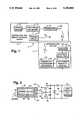
- FIG. 1is a block diagram illustrating an electronic identity system having an information and identity storage device and an interrogation station and embodying the present invention
- FIG. 2is a schematic diagram illustrating one embodiment of a vibrationally driven power source for the information and identity storage device of FIG. 1;
- FIG. 3is a block diagram of a logic circuit in the information and identity storage device of FIG. 1;
- FIG. 4is a schematic diagram of a microwave triggered circuit of the information and identity storage device of FIG. 1;
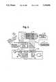
- FIG. 5is a block diagram of the interrogation station of FIG. 1;
- FIG. 6is a block diagram showing the coded signal receiver of the interrogation station of FIG. 5;
- FIG. 7is a diagram of the identification system of the invention as installed on a bidirectional, four lane highway, particularly showing the location of individual lane triggering and receiver antennas;
- FIG. 8Ashows a single lane portion of the four lane highway of the type shown in FIG. 7 having positioned therein a 130 kHz. triggering loop and a 2450 MHz. leaky coax antenna;
- FIG. 8Bshows another single lane portion of the four lane highway of the type shown in FIG. 7 having positioned therein a 130 kHz. triggering loop antenna and a 915 MHz. colinear array receiving antenna;
- FIG. 8Cshows a single lane portion of the four lane highway of the type shown in FIG. 7 having positioned therein a 915 MHz. colinear array, triggering pulse transmitting and a 915 MHz. colinear array data receiving antenna;
- FIG. 8Dshows a single lane portion of the four lane highway of the type shown in FIG. 7 having positioned therein a single 915 MHz.
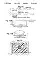
- FIG. 9is an isometric view of the antenna and a reflective shield or channel housing embodying the present invention, showing details of the positioning of the channel in a roadway of a highway and the position of the antenna in the channel;
- FIG. 9Ais an isometric view of the colinear array antenna of FIG. 9, showing further details of its construction
- FIG. 9Bis an additional depiction of a portion of the colinear array of FIG. 9A, showing two complete elements and a partial element constructed from coaxial cable;
- FIG. 9Cis a graphic depiction of the current distribution in the center conductor of the coaxial cable elements of the array of FIG. 9B;
- FIG. 9Dis a further graphic depiction of the current distribution in the sheath of the coaxial cable elements of the antenna of FIG. 9B;
- FIG. 10is a sectional view taken substantially along line 10--10 of FIG. 9, showing details of the colinear array antenna and the reflecting shield;
- FIG. 10Ais a partly sectional view of the colinear array antenna of FIG. 8D, in an operative position showing details of the radiation signal pattern of the colinear array antenna in a direction parallel with the colinear array;
- FIG. 10Bis an elevational view of the roadway of FIG. 9, showing the pattern of radiated energy from the colinear array antenna and reflecting shield of FIG. 9;
- FIG. 11is a diagrammatic representation of the sequence of triggering and data pulses transmitted and received by an interrogation station positioned adjacent a fourth lane of a four lane highway;
- FIG. 12is an isometric view of one form of a leaky coax radiating element
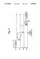
- FIG. 13is a timing diagram of information exchange between an interrogator and transponder of an embodiment
- FIG. 14is a bock diagram of a logic circuit in the information and identity storage device for use with a single transmit and receive antenna;
- FIG. 15is a flow diagram of functions performed by an embodiment of the interrogation station of FIG. 1;
- FIG. 16is a flow diagram of the functions performed by information and identity storage device (transponder) of FIG. 14;
- FIG. 17illustrates an embodiment the advantageous placement of the vehicle antenna on the vehicle license plate
- FIG. 18is a diagrammatic representation of the use of trigger pulses to convey data.
- an electronic identification system 8includes a transponder or identification and identity storage device 10 and a fixed transponder or interrogation station 11.
- the information and identity storage device 10includes a power source 12, a logic circuit and a memory 13, a receiver and trigger circuit 14 with a first antenna 15, a radio frequency transmitter 16 and a second antenna 17.
- the interrogation station 11includes a receiver 18 with an antenna 19 of an antenna array, a decoder 20, a data processor 21, which provides data format memory and control functions, and a trigger interrogation pulse sequence generator and a transmitter 22 with an antenna 23.
- the data processor 21aids in the decoding process, formats the data for communication with a central data processing unit (not shown) and generally controls the functions of the interrogation station 11. In general, the complexity of the data processor 21 depends on the particular function which the electronic identification system 8 is required to perform.
- the power from the power source 12 for data retention in the memory of the information and identity storage device 10must be present at all times unless an EEROM is used and so a battery is required.
- the batterycould be supplemented by other power sources including energy transfer from inductive or radio frequency energy fields, of which several examples exist in prior art, or inertial field generation as described herein.
- the power requirementsare such that available batteries could provide up to a 20 year operational lifetime without supplemental sources of energy.
- a means for producing power for data transmissionis from the inertial field.
- FIG. 2illustrates an inertial energy generator where electric power is derived from the vibration or vertical movement of the moving object.
- a small mass 30is shown mounted in a frame 31 on one end of a resilient strip 32.
- Piezoelectric material 33is bonded to each side of the strip 32, and a movement of the mass 30, causing deflection of the strip 32, generates an alternating voltage.
- Leads 34 from the piezoelectric material 33feed to a circuit where rectification and doubling of the voltage is performed by the diodes 35, 36 and the energy storage capacitors 37, 38.
- an ordinary full-wave or half-wave rectifiermay be used if the higher voltage is not required.
- the direct current energyeither can be stored in the capacitors 37, 38 or in a rechargeable battery 39.
- a means for limiting the maximum voltageis provided in the form of a Zener diode 40, by a number of diodes in series, or by a voltage regulator circuit.
- the contents of the memoryare maintained by the battery power source 12 which provides sufficient energy to the transmitter 16 so that the coded signal is completely transmitted before the stored power drops low enough to stop the data transmission.
- the transmitter 16draws little power from the power source 12, in its quiescent state, allowing excess generated energy from the power source 12 to be stored for later transmission.
- the data to be transmitted from the information and identity storage device 10must be formatted in such a way that the desired information is conveyed accurately. While the following scheme is the preferred embodiment for marking railroad cars, a number of variations are possible. In general, the data will contain coded information to designate the owner of the car and the car's serial number in a protected portion of the memory.
- Data bitscan be coded in various ways. For North American railroad applications, where cars associated with various owners are intermixed, a code is allocated to the protected portion of the memory frame as follows:
- the data code streamcontains either a means of self-synchronization relying on the code format, or an external or inherent method of synchronization is provided.
- synchronization in some formis provided at the interrogation station 11 to clock the identification device 10.
- An alternative solutionis to provide an absolute time source such as a clock, with the identification device 10.
- the clockshould be stable enough so that synchronization of the second independent clock in the interrogation station 11 is maintained within a single bit interval for the period of time required to transmit the coded signal from the moving information and identity storage device 10 to the stationary interrogation station 11.
- the availability of low cost, accurate timing crystals for wristwatch manufacturemake the use of a non-return to zero (NRZ) code feasible for the code signal since the timing is predictable enough for data recovery.
- the low power consumption of these devicesallows lifetimes of up to 20 years on available batteries.
- One operating feature of the information and identity storage device 10is the code rate employed for the coded signal.
- High code ratesallow for many read operations at high vehicle speeds, but are more difficult to decode and consume more power.
- Typical microwave antennasallow a reading window of about 300 mm. A transmitter spends about 3.5 milliseconds in this window when traveling at 320 km./hr. Assuming at least three transmissions to be received, the total time for each transmission would be about one millisecond.
- a typical transmissioncomprises eight preamble bits and sixty four data bits so that a sufficient code rate is about 64 kHz. Doubling the frequency of a watch crystal provides a convenient rate of 65.5 kHz. with acceptably low power.
- the transmittercan be read approximately ten times with consequent improvement in accuracy.
- the maximum transponder carrying vehicle speedis 80 km./hr., which is more than adequate for those locations at which this quantity of information is required.
- spacing of information and identity storage devices 10 on adjacent railway carscan be of the order of a meter without any difficulty.
- Increased data rates for use with high speed vehicles or vehicles traveling multiple lane roadways or trackscan be provided by the transponder 10 and interrogator or reader 11 disclosed herein, and will be later described.
- FIG. 3A block diagram of the logic circuit 13 is shown in FIG. 3.
- the logic circuit 13will be familiar to those skilled in the art.
- the entire information and identity storage device 10is realized in a single CMOS integrated circuit or circuits.
- the trigger circuit 14resets the flip-flop 52 and the counters 53 and 54 and auxiliary counter 55 are allowed to count.
- Counter 54sequentially selects memory addresses which cause the contents of the preamble store 56 and the first memory page 57 to be output through the transmitter 16 to the antenna 17, which consequentially sends out a coded signal.
- the program mode and page select circuit 59allows memory paging or programming mode entry. Access to the first thirty four bits is controlled by the light-activated switch 60. Data entry is also through the trigger circuit 14.
- the information and identity storage device 10is returned to its quiescent state either when counter 54 reaches the end of its count, signifying that all bits have been sent, or when auxiliary counter 55 ends its count.
- the trigger circuit 14may take one of several forms depending on the specific application.
- the characteristics of the trigger circuit 14are as follows:
- Trigger initiationis effected by an impulse rather than a steady state condition.
- the trigger circuitis passive in the sense that its operational power is obtained from the triggering signal and it consumes no energy in the quiescent state.
- FIG. 4shows a trigger circuit suitable for receiving an interrogation signal 70 in the form of electromagnetic radiation, demodulating the burst with diodes 71 and capacitors 72 and matching the appropriate input impedance With a pulse transformer 73.
- a timed sequence of interrogation pulsesis sent.
- a different sequence of pulsesallows the memory to be written to, this access only being permitted to "write protected” portions of memory unless the protect switch is illuminated.
- the individual bits of memoryare also programmed using appropriately timed interrogation pulses.
- antennas 15 and 17are included in the information and identity storage device or transponder 10 . These could take various forms but in one embodiment, they operate at microwave frequencies. Both antennas 15 and 17 and also all other circuitry in the device are mounted on a sheet of low loss material.
- the antennasmay consist of patches or arrays of patches of conductive material whose design would be familiar with ones skilled in the art. The configuration of the patches is dependent on the frequency of operation and the desired antenna patterns.
- One antennais associated with the trigger circuit 14 described above, and the other is connected to the transmitter 16, which is a single stage device arranged to produce energy at the desired frequency. A power output of one to ten milliwatts is more than sufficient for reliable operation of the electronic identification system 8.
- the operating frequencies of the data link and the triggering linkare different, but since the trigger circuit and the data circuit do not transmit at the same time, they may be the same.
- FIG. 5illustrates a more detailed arrangement of the interrogation station 11.
- the embodiment shownrepresents one configuration suitable for railroad applications.
- Alternative interrogation stations and receiving antennasmay be employed.
- Three microwave interrogator signal sources with antennas 80, 81 and 82are shown. One is located on each side and one between the two ties of the railroad track to allow reading of the information and identity storage devices on either side or under the cars.
- a coded signal receiver 83which is similar to the receiver 18, with antennas 84, 85 and 86 on either side in between the tracks is located beside the track along with the rest of the interrogation equipment 87, 88.
- the receiver 83is shown in more detail in FIG.
- the operating frequency in the railroad applicationis chosen to minimize noise and unwanted signals and is typically in the 2500 MHz region although other frequencies such as 915 MHz. can be used as well.
- Detected and amplified signals from the receiver 83are fed to the decoder 87 and microprocessor system 88 where they are checked for accuracy and stored or transmitted to a host computer as required. Synchronization with the transmitter 16 takes place in the decoder circuit 86 which has an absolute time reference on the same frequency as the transmitter 16.
- wheel contactsprovide supplemental information such as speed and direction of the train. Wheel contacts indicate when the whole train has passed, and at this time the data is assembled in a format compatible with the central data processor to which it is sent either in response to an interrogation or on its own request. It is also possible to use reflected signals from the interrogating beam to determine the speed and direction of the vehicle using the Doppler effect.
- the electronic vehicular identification system 8 disclosed hereinmay also be used to identify moving vehicles on multi-lane highways, however, substantial difficulty may be encountered due to random arrival of vehicles at the reading or interrogating station 11, and in particular, movement of the vehicle's transponder 10 over an interrogating loop or antenna. Since there is a high probability that multi-vehicle traffic will be simultaneously present at the interrogating antenna location, in order to properly monitor road traffic at a given point, it is necessary to distinguish not only between successive vehicles in a given lane, but to distinguish the particular lane occupied by a given vehicle that passes over the interrogation antenna.
- the present inventionprovides an apparatus and a method which provide positive identification of vehicles travelling in the same and opposite directions along multi-lane highways.
- two to four lanesare monitored with identification of vehicles having a nominal transponder spacing of 3 feet traveling at typical speeds of 70 m.p.h.
- vehicle speed and transponder spacingcan be varied through the use of greater data rates.
- FIG. 7shows in diagrammatic form, a typical multi-lane highway installation wherein four lanes of opposing direction traffic 101 and 103 travel along a highway 109.
- a colinear triggering antenna or alternately a triggering loop antenna 100typically radiating at a frequency of 130 kHz.
- a colinear antenna array 102radiating or receiving at a frequency of 2450 MHz.
- the colinear antenna array 102will be known to those skilled in the art as leaky coax, as disclosed in U.S. Pat.
- No. 3,691,4808the disclosure of which is incorporated herein by reference. It comprises a coaxial cable 102a, as may best be seen in FIG. 12, having a perforated outer conductor 102b for radiation of electromagnetic energy through a plurality of openings 102c therein.
- FIGS. 8A, 8B, 8C, and 8Dshow the signal intensity of radiation pattern of the operating colinear array antenna 102. As shown, the signal intensity pattern defines a transponder capture zone.
- the system of FIG. 7utilizes individual lane triggering antennas 100, and receiving antennas 102, as will be discussed later.
- transponder interrogating or triggering pulse 104transmitted by a triggering antenna or loop 100.
- interrogator or reader 120stores the non-response indicating an interrogating transmission on lane 1.
- the second interrogating pulse 108noted as lane 2, is transmitted from the antenna 100, and if no transponder response is received during the interval 110, a third interrogator pulse 112, noted as lane 3, is transmitted with an additional wait for a receiving period 114.
- the fourth interrogating pulse 116is transmitted and receives a transponder response 118.
- the transmitted interrogating pulseis delayed by 2,000 microseconds in order to provide additional time to receive a transponder message, typically containing 128 information bits, at a data rate of 65 kHz.
- the "record keeping” i.e., lane counting, and redundant reads in the case of improper data receptionis under the control of an interrogator 120.
- This approachprovides successful monitoring for moving vehicles in multi-lane roadways.
- the electronic identification system 8operates under conditions wherein there is a nominal spacing between transponders 10 in any lane configuration on vehicles moving at rates of 120 feet per second, or 72 m.p.h.
- the inventionfurther provides an antenna having a transponder capture or zone of approximately three feet along the path of the moving vehicle. With this configuration, information data rates of 65 kHz. and vehicle speeds, each lane's capture zone is occupied by a given vehicular transponder for at least 30 milliseconds.
- a 128 bit message received from the transpondercan be received in approximately two milliseconds, providing a large time interval where multiple reads of the same transponder 10 can be obtained in order to improve the statistical return signal accuracy.
- a leaky coax antennais operated at a frequency of 2450 MHz.
- the use of available lower frequencies, typically 915 MHz. for both triggering and data transfer from the data transponder 10allows read intervals adequate to insure accurate detection and identification of the moving vehicles.
- this inventiondiscloses the discovery that equivalent operation can be achieved at data rates of 500 kHz. or kilobytes per second.
- Thisprovides a relatively large increase in the effective capture zone of the particular colinear antenna configuration shown in FIGS. 10A and 10B, thereby allowing vehicular speeds in the vicinity of 100 m.p.h., and more importantly provides a system capability of multiple transponder read cycles for essentially simultaneous occupancy of a multiple lane highway by vehicles which may be moving in either direction.
- FIGS. 7 and 8Afurther show an interrogator or reader 120 in signal communication with an antenna or loop 100 and the antenna 102. This arrangement is common to roadway interrogating stations disclosed, providing communication and information processing between road antennae, and auxiliary computing equipment.
- the lane configuration of FIG. 8Bconsists of interrogator trigger loop alternate 120, which is similar to the loop 100 discussed above, for delivering a trigger or turn-on pulse at 130 kHz.
- interrogator trigger loop alternate 120which is similar to the loop 100 discussed above, for delivering a trigger or turn-on pulse at 130 kHz.
- a colinear antenna array 122utilized as an antenna for receiving a transponder signal 118 during the transponder response interval 106 to the triggering pulse 116 transmitted by the loop 120.
- Use of the colinear antenna array 122provides an advance in the art of transponder communication, in that receiving signal strength from the transponder 10 is greatly improved.
- yet an additional embodiment of the inventioncomprises parallel colinear array antennas for transmitting a trigger pulse from one array and interrogating a mobile transceiver 10 and receiving the transponder signal from the other.
- the configuration of FIG. 8Cis placed in and substituted for the loop 100 and colinear antenna 102 of FIG. 7.
- Replacement of the interrogating loops 100 and/or 120 by a colinear transmitter array 122provides an advantage in that the antenna 122 provides signal gain and directivity from the interrogation station 11 to the transponder 10 for transmitting trigger pulses to, in reprogramming the transponder 10.
- the colinear array receiving antenna 122provides increased directivity and signal gain for data received from the low power transponder 10.
- a further embodiment of the invention disclosed hereinis shown in the individual lane element of FIG. 8D.
- a single colinear array operating at 915 MHzis used for both transmitting and receiving with the use of a microwave directional coupler or circulator 126 wherein the triggering and interrogation signal is supplied by a conductor 127 and transponder response signals are received via the conductor 127.
- This configurationis a further advance in the art of identifying and communication with moving vehicles in that only a single roadway groove is required.
- 915 MHz.as a communication frequency for the electronic identification system is dictated by the availability of this frequency for devices of this type. As such, it is a reasonable compromise with respect to interference from other services and devices, debris penetration, and availability of components at reasonable cost.
- the colinear array suitable for installation in the roadway surfacehas provided signal directivity and gain in the direction upwards of the road surface.
- the antennaconsists of the colinear array assembly 122 consisting of a colinear element array 124, as may best be seen in FIG. 9A, mounted internally of a U-shaped open channel or shell comprising a reflective shield 123.
- An antenna array 124 comprised of coaxial cableis mounted in the channel 123 inside a protective tubular housing 128 mounted somewhat centrally and internal of the reflective shield 123.
- a dielectric material 130filling the reflective shield.
- the use of a material having a dielectric constant greater than 1.0 and high compressive strength, water resistance, and the ability to bond to both the reflective shield 123 and the housing 128,improves signal transmission by increasing the signal strength above the roadway, and provides protection from the vehicles on the road.
- the antenna array 124is laterally centered closer to the road surface 125 than the bottom of the metal shield 123, substantially increasing the radiated signal upwards through the shield open end and upward from the road surface 125.
- the disclosed antennafurther provides an advantage in that the reflective shield 123 eliminates any dependence on the dielectric constant or radio frequency characteristics of commonly used pavements, resulting in predictable performance in roadways having highly variable radio frequency loss characteristics.
- the reflective channel of FIG. 10comprises a metal shield having a three-inch width, with the colinear antenna assembly 124 disposed equidistant from the sides of the shield 123 and approximately one inch from the lower surface. The channel is cemented or retained in a roadway groove, after which the antenna assembly properly supported from one edge of the road to the other is, "potted" with dielectric material 130 in the metal shield 123, as shown in FIGS. 9 and 10.
- FIGS. 10A and 10BThe improvement in radiating signal characteristics of the colinear array disclosed herein is particularly shown in FIGS. 10A and 10B.
- FIGS. 10A and 10BThe improvement in radiating signal characteristics of the colinear array disclosed herein is particularly shown in FIGS. 10A and 10B.
- the radiation pattern, or transponder zone capture of the antenna shown in FIG. 10Bincreases the occupancy time of moving transponders providing, as discussed above, an improved accuracy in data transfer from low power transponders to interrogator.
- FIG. 9A, 9B, 9C, and 9Dthere is shown a detailed depiction of a typical portion of the colinear array 124.
- one embodimentutilizes lengths of coaxial cable cut to one-half wavelength at the operating frequency and connected conductor-to-shell, as shown, in order to obtain the required phase reversal in each other half-wave section, resulting in a plurality of in-phase radiating elements which increases the radiated signal strength over that provided by an identical number of dipoles.
- a unique advantage of the colinear array 124, as incorporated in a road antenna in this invention,lies in its completely modular construction. It is possible to utilize this antenna construction in identifying vehicles over roads having varying widths and numbers of lanes by merely adding additional half-wave sections.
- a quarter-wave matching stub 134At the input end 132 of the antenna assembly 124, there is shown a quarter-wave matching stub 134. Also at the free end of the antenna 135, there is an additional quarter-wave matching stub 137 having an additional capacitive end 139.
- a quarter-wave matching stub 134At the input end 132 of the antenna assembly 124, there is shown a quarter-wave matching stub 134. Also at the free end of the antenna 135, there is an additional quarter-wave matching stub 137 having an additional capacitive end 139.
- FIG. 18A further portion of the invention disclosed, as may best be seen in FIG. 18 which is presented as an alternative embodiment to that shown in FIG. 11.
- the reader or interrogatorcan encode data into the trigger pulse in order to transmit additional data to the transponder 10.
- the trigger signal 144 transmitted from the interrogation station 11comprises a 25 microsecond coded portion 146 at a data rate of 1 MHz, followed by a 25 microsecond uncoded pulse 147.
- the information transmitted to the transponder in this mannerwould be passed on to other systems or devices in the vehicle, including but not limited to a dashboard display.
- this dashboard displaycan take many forms including gas discharge displays and/or onboard cathode ray tube monitors.
- Information transmitted in this mannertypically can be road conditions, geographic positional data, emergency information for driver reaction or changing speed limits.
- the placement of the vehicle antenna for signal exchange with roadway surface antennasis also important. Mounting the antenna to a vehicle license plate as shown in FIG. 17 has been found to provide significant advantages.
- the antennais a part of the transponder housing 260 and is mounted to the front license plate of a car. Mounting on the license plate is relatively simple and provides a secure antenna location having good RF exposure to road surface antennas.
- interrogator 11and an information and identity storage device or transponder 10 and their cooperative interaction. Included in their interaction is the ability of the interrogation station 11 to program or change memory 57 of transponder 10. In many cases, such memory changes are of great importance to the proper record keeping of the system. For example, when the data to be change represents the current weight of the vehicle as measured by a weigh in motion device (WIM), the stored data may become the basis of road taxes or overweight penalties. Accordingly, proper recording of such data is of extreme importance.
- WIMweigh in motion device
- the present embodimentpresents new methods and apparatus of operating the interrogator 11 and transponder 10 to provide necessary security in data handling.
- the apparatus of the present embodimentvaries from that of previous disclosed embodiments in that the functions performed thereby are changed. As will be understood by those of ordinary skill in the art, such new functions can be easily provided by well known time and signal responsive circuitry or by a computerized controller programmed to respond to signals and the passage of time.
- FIG. 13is a timing diagram showing the timed relationship of the signals exchanged in the present embodiment.
- This timed relationship and the data transmission rates employedprovide a system in which an interrogator can read the information stored in a moving transponder, process the information, program new information into the transponder memory based on the priorly read information and read the newly programmed information to assure its accuracy of storage.
- the present per-lane sequence(FIG. 13) can be used with priorly discussed multiplexing techniques so that one interrogator 11 can sequentially communicate with eight different moving transponders each in a different physical location (highway lane) and three complete accesses of the type above can be made within the capture window of the system.
- FIG. 13shows a sequence of operations undertaken for a single lane of traffic flow and includes operations undertaken by both the interrogator 11 and the transponder 10.
- Interrogator 11periodically transmits first trigger pulses 150 which go unused until a transponder is within the capture window of the system. When a transponder is in the vicinity of a trigger pulse 150, it automatically responds by transmitting a first data message comprising 128 bits from its memory 57 as is represented at 152. (152 also represents a reception interval by the interrogator 11). Interrogator 11 then processes the received data during interval 154 to make sure of the accuracy of its reception and to determine what new data is to be written into transponder 10.
- transponder 10 in 152if the data read from transponder 10 in 152 consists of a credit balance for the payment of road use tolls, interrogator 11, during processing 154 will subtract the most recent toll from the credit balance.
- a second data message including the processed datais then written from interrogator 11 to transponder 10 in the time designated 156. Since the original transmission 152 from the transponder 10 includes fixed data concerning the vehicle associated with the transponder, the return message 156 is substantially shorter since this fixed data need not be re-transmitted.
- the data received by transponder 10 during interval 156is stored into the memory of transponder 10 upon reception.
- the next signal transmitted in the present embodimentis a second trigger pulse 158 which is transmitted by interrogator 11 a predetermined period of time after the transmission of trigger pulse 150.
- trigger pulse 158is transmitted at such a time that the information transmitted to transponder (156) will be stored in the memory of transponder 10 prior to the transponder's response to trigger pulse 158.
- transponder 10transmits from its memory a third data message 160 which represents the content of its memory as modified by the recent transmission 156 from interrogator 11.
- Interrogator 11checks the content of the data 160 to make sure that the data accurately represents the changed data 156.
- the data in the moving transponder 10was read by interrogator 11, modified by interrogator 11 and reread by interrogator 11 to guarantee that the modifications have been accurately stored.
- FIG. 13shows a cooperative information exchange between an interrogator 11 and a transponder 10 in a single lane of traffic.
- the same sequencewill begin again in another lane of traffic to perform the same operations with any transponder within the capture window in that lane.
- the processcontinues through each successive surveyed lane of traffic up to, for example, eight, and then begins again with the first lane of traffic.
- the use of appropriate timing intervals and data ratesassures that eight lanes of traffic can be scanned as shown in FIG. 13 and at least three complete scan cycles will be performed for each lane. Performance of this sequence three times per lane provides greater assurance of accuracy of the cooperative action.
- the transmitting and receiving frequencyis the previously discussed 915 megahertz and the rate of data transfer is 500 K-bits per second.
- Each transmission from transponder 10(152 and 156, FIG. 13) comprises 128 bits (256 microseconds at 500 per second) which includes 64 bits of memory protected vehicle identification information and 64 bits of changeable data such as vehicle weight and/or toll credit balance.
- the transmission (156, FIG. 13) from interrogator 11comprises 64 bits (128 microseconds) of changeable data for the vehicle identified in the 128 bit transmission 152.
- trigger pulses 150 and 158each last 20 microseconds and the processing period 154 lasts 100 microseconds.
- the dotted vertical lines of FIG. 13identify the specific times at which events occur and each is labelled with a specific time in microseconds measured from the start of trigger pulse 150.
- the sequence for each lanerequires 785 microseconds when a five microsecond period is blanked between the end of one sequence and the trigger pulse 150 starting the sequence in the next lane.
- Scanning eight lanes of traffic three times eachrequires 24 lane scan periods of the type shown in FIG. 13 or approximately 18.84 milliseconds.
- a vehicle travelling at 100 miles per hourcovers approximately 2.75 feet in 18.84 milliseconds. So a transponder and interrogator antenna system with a capture zone in access of 2.75 feet used as above described, provides three secure data exchange cycles in each active lane of traffic. When the capture zone is constructed to be three or perhaps four feet as is achievable with current antenna technology, the security of data exchange is further improved.
- FIG. 14is a block diagram of an alternative embodiment of the logic circuit 13, trigger circuit 14 and transmitter 16 of information identity and storage device (transponder) 10.
- This alternative embodimentutilizes a single antenna and a modified arrangement for detecting trigger pulses and data received by the single antenna.
- This alternative embodimentincludes a diplexer 202 which connects antenna 200 to a detector circuit 204 and transmitter 16.
- Diplexer 202is of a type well known in the art and connects incoming signals received by the antenna 200 to detector 204 unless a signal transmission from transmitter 16 is occurring. Whenever signals to be transmitted are applied to conductor 215 by transmitter 16, the connection from antenna 200 to detector 204 is broken and the signals on conductor 215 are connected to antenna 200 for transmission.
- Detector 204receives incoming signals and applies a detected representation of those signals to program mode and page select circuit 59 and to a trigger circuit 14' via a path 207.
- Trigger circuit 14'detects the approximately 20 microsecond trigger pulse from interrogator 11 and a response thereto enables previously discussed timing circuitry and program mode and page select circuit 59.
- circuit 59reads 128 bits from memory 57 and sends the bits read to transmitter 16 via preamble store 56 for transmission.
- Circuit 59also controls memory 57 to store the incoming 64 bits of transmission 156 from interrogator 11. All incoming bits are applied to circuit 59 and gated therefrom for storage in memory 57 in response to timing signals applied to circuit 59.
- Circuit 59responds to the second trigger pulse 158 by reading 128 bits from memory 57 and transmitting the bits so read via antenna 200 to interrogator 11.
- FIG. 14also includes a tamper protection circuit 209 which detects unauthorized attempts to modify transponder 10 by for example, changing the content of memory 57 in an inappropriate manner and writes information into memory 57 describing such an occurrence for later analysis.
- tamper protection circuit 209may write into memory 57 a combination of bits giving notice of tampering which will be detected when the memory 57 is next read.
- FIG. 15is a flow diagram of the functions performed by interrogator 11 in the performance of the information exchange of FIG. 13.
- the flowbegins with a block 220 in which trigger pulse 150 is transmitted.
- Block 221is then performed as a loop to determine if a response to the trigger pulse is received.
- data 152(FIG. 13) will be received in block 223 and immediately processed by data format memory and control 21 of the interrogator in a block 225.
- new data 156(approximately 100 microseconds) is transmitted in block 227 to the transponder 10.
- Thisis followed by the transmission of a second trigger pulse in block 228.
- the response 160 by transponder 10 to the second trigger pulseis received in block 230 and a pause (block 232) is initiated before proceeding to the performance of the same sequence in the next lane (block 233).
- FIG. 16represents the sequence of steps performed by transponder 10. This sequence begins with a block 240 in which transponder 10 is awaiting a trigger pulse. The performance of block 240 is for the most part, a passive performance so that little or no energy is expended between the reception of trigger pulses.
- transponder 10When a trigger pulse is detected in block 240, transponder 10 immediately sends 128 bits of data (block 242) via antenna 200. After sending data 152 transponder 10 is passive for the 100 microsecond period it takes to process the data in interrogator 11. Thereafter, transponder 10 receives in block 244, the 64 data bits 156 from interrogator 11 which are stored in memory 57 step 246.
- transponder 10Upon the reception of trigger pulse 158 immediately after data storage in block 246, transponder 10 transmits data 160 via antenna 200 and returns to the beginning state of awaiting an initiating trigger pulse.
- a first trigger pulse 160starts a sequence which runs through block 250 and returns to await the start of the sequence again when a subsequent trigger pulse 150 is received.
- the FIG. 16 sequencemay be initiated by the same interrogator 11 or the interrogator 11 of another vehicle identification arrangement elsewhere.
Landscapes
- Engineering & Computer Science (AREA)
- General Physics & Mathematics (AREA)
- Physics & Mathematics (AREA)
- Theoretical Computer Science (AREA)
- Computer Networks & Wireless Communication (AREA)
- Microelectronics & Electronic Packaging (AREA)
- Computer Hardware Design (AREA)
- Mechanical Engineering (AREA)
- Artificial Intelligence (AREA)
- Computer Vision & Pattern Recognition (AREA)
- Business, Economics & Management (AREA)
- Finance (AREA)
- Traffic Control Systems (AREA)
- Radar Systems Or Details Thereof (AREA)
- Near-Field Transmission Systems (AREA)
Abstract
Description
Claims (14)
Priority Applications (6)
| Application Number | Priority Date | Filing Date | Title |
|---|---|---|---|
| US07/539,703US5196846A (en) | 1980-02-13 | 1990-06-18 | Moving vehicle identification system |
| EP91912603AEP0487708B1 (en) | 1990-06-18 | 1991-06-10 | Moving vehicle identification system |
| AU81861/91AAU8186191A (en) | 1990-06-18 | 1991-06-10 | Moving vehicle identification system |
| PCT/US1991/004081WO1991020067A1 (en) | 1990-06-18 | 1991-06-10 | Moving vehicle identification system |
| DE69126100TDE69126100T2 (en) | 1990-06-18 | 1991-06-10 | IDENTIFICATION SYSTEM FOR MOVING VEHICLES |
| PT98012APT98012A (en) | 1990-06-18 | 1991-06-18 | DEVICE FOR IDENTIFICATION OF VEHICLES IN MOVEMENT |
Applications Claiming Priority (8)
| Application Number | Priority Date | Filing Date | Title |
|---|---|---|---|
| GB8004851 | 1980-02-13 | ||
| US23457081A | 1981-02-13 | 1981-02-13 | |
| US53601083A | 1983-09-26 | 1983-09-26 | |
| US66171284A | 1984-10-17 | 1984-10-17 | |
| US07/195,400US4870419A (en) | 1980-02-13 | 1988-05-13 | Electronic identification system |
| US07/383,169US4937581A (en) | 1980-02-13 | 1989-07-20 | Electronic identification system |
| US07/446,234US5164732A (en) | 1980-02-13 | 1989-12-05 | Highway vehicle identification system with high gain antenna |
| US07/539,703US5196846A (en) | 1980-02-13 | 1990-06-18 | Moving vehicle identification system |
Related Parent Applications (1)
| Application Number | Title | Priority Date | Filing Date |
|---|---|---|---|
| US07/446,234Continuation-In-PartUS5164732A (en) | 1980-02-13 | 1989-12-05 | Highway vehicle identification system with high gain antenna |
Publications (1)
| Publication Number | Publication Date |
|---|---|
| US5196846Atrue US5196846A (en) | 1993-03-23 |
Family
ID=24152302
Family Applications (1)
| Application Number | Title | Priority Date | Filing Date |
|---|---|---|---|
| US07/539,703Expired - LifetimeUS5196846A (en) | 1980-02-13 | 1990-06-18 | Moving vehicle identification system |
Country Status (6)
| Country | Link |
|---|---|
| US (1) | US5196846A (en) |
| EP (1) | EP0487708B1 (en) |
| AU (1) | AU8186191A (en) |
| DE (1) | DE69126100T2 (en) |
| PT (1) | PT98012A (en) |
| WO (1) | WO1991020067A1 (en) |
Cited By (109)
| Publication number | Priority date | Publication date | Assignee | Title |
|---|---|---|---|---|
| US5396233A (en)* | 1991-02-04 | 1995-03-07 | Hofmann; Wilhelm H. | Arrangement for identifying motor vehicles |
| WO1995020172A1 (en)* | 1994-01-21 | 1995-07-27 | Vorad Safety Systems, Inc. | Vehicular radar wayside transponder system |
| US5448242A (en)* | 1994-04-26 | 1995-09-05 | Texas Instruments Incorporated | Modulation field detection, method and structure |
| US5450087A (en)* | 1994-04-06 | 1995-09-12 | Texas Instruments Incorporated | Transponder maintenance mode method |
| US5471212A (en)* | 1994-04-26 | 1995-11-28 | Texas Instruments Incorporated | Multi-stage transponder wake-up, method and structure |
| US5477215A (en)* | 1993-08-02 | 1995-12-19 | At&T Corp. | Arrangement for simultaneously interrogating a plurality of portable radio frequency communication devices |
| US5488376A (en)* | 1994-04-26 | 1996-01-30 | Texas Instruments Incorporated | Transponder interface circuit |
| US5520056A (en)* | 1993-04-01 | 1996-05-28 | Etat Francais | Process for conditioning and for placing a traffic sensor |
| US5525992A (en)* | 1994-11-14 | 1996-06-11 | Texas Instruments Deutschland Gmbh | Method and system for conserving power in a recognition system |
| US5557268A (en)* | 1992-12-16 | 1996-09-17 | Exxon Research And Engineering Company | Automatic vehicle recognition and customer automobile diagnostic system |
| US5587712A (en)* | 1993-11-12 | 1996-12-24 | Mark Iv Transportation Products Corp. | Transponder having microprocessor generated frequency shift signals |
| US5621571A (en)* | 1994-02-14 | 1997-04-15 | Minnesota Mining And Manufacturing Company | Integrated retroreflective electronic display |
| US5646632A (en)* | 1994-11-14 | 1997-07-08 | Lucent Technologies Inc. | Method and apparatus for a portable communication device to identify its own location |
| US5712630A (en)* | 1994-07-26 | 1998-01-27 | Matsushita Electric Works. Ltd. | High power moving object identification system |
| US5737280A (en)* | 1994-11-21 | 1998-04-07 | Univert Inc. | Clocking system for measuring running speeds of track runners |
| US5751227A (en)* | 1994-12-22 | 1998-05-12 | Nippondenso Co., Ltd. | Communication system for vehicles |
| WO1998020470A1 (en)* | 1996-11-07 | 1998-05-14 | Robert Tyburski | Residual charge effect traffic sensor |
| US5781106A (en)* | 1994-09-16 | 1998-07-14 | Inmed B.V. | Device and method for the telecontrol of an object |
| US5818348A (en)* | 1995-03-13 | 1998-10-06 | Motorola, Inc. | Method and radio frequency identification system for a novel protocol for reliable communication |
| US5864304A (en)* | 1996-08-08 | 1999-01-26 | At&T Corp | Wireless railroad grade crossing warning system |
| WO1998053557A3 (en)* | 1997-05-16 | 1999-02-25 | Koninkl Philips Electronics Nv | Transponder communication device |
| US5900825A (en)* | 1996-08-01 | 1999-05-04 | Manitto Technologies, Inc. | System and method for communicating location and direction specific information to a vehicle |
| US5917433A (en)* | 1996-06-26 | 1999-06-29 | Orbital Sciences Corporation | Asset monitoring system and associated method |
| US5942993A (en)* | 1996-08-28 | 1999-08-24 | Toyota Jidosha Kabushiki Kaisha | Lane change detecting system for mobile bodies and mobile body detecting device employed in such system |
| US5952941A (en)* | 1998-02-20 | 1999-09-14 | I0 Limited Partnership, L.L.P. | Satellite traffic control and ticketing system |
| US5987374A (en)* | 1996-07-08 | 1999-11-16 | Toyota Jidosha Kabushiki Kaisha | Vehicle traveling guidance system |
| US6025784A (en)* | 1998-02-12 | 2000-02-15 | Micron Technology, Inc. | Vehicles, license plate frame assemblies, methods of forming license plate frames, and methods of attaching RFIDs, transponders and modulators to vehicles |
| US6088680A (en)* | 1994-06-21 | 2000-07-11 | Fujitsu Limited | Automatic toll adjusting system, and storage medium with a radio communication function, frequency converting apparatus, writing apparatus, settling apparatus, depositing apparatus and inquiring apparatus therefor |
| US6099178A (en)* | 1998-08-12 | 2000-08-08 | Eastman Kodak Company | Printer with media supply spool adapted to sense type of media, and method of assembling same |
| US6112152A (en)* | 1996-12-06 | 2000-08-29 | Micron Technology, Inc. | RFID system in communication with vehicle on-board computer |
| WO2000054238A1 (en)* | 1999-02-12 | 2000-09-14 | Privacy Shield L.L.C. | Adjustable shield for vehicle mounted toll collection identifier |
| WO2001007290A1 (en)* | 1999-07-23 | 2001-02-01 | Hm Electronics, Inc. | Vehicle identification system and method of using same |
| US6191705B1 (en) | 1999-03-17 | 2001-02-20 | Mark Iv Industries, Limited | Radio frequency highway management system |
| US6219596B1 (en)* | 1997-09-18 | 2001-04-17 | Mitsubishi Denki Kabushiki Kaisha | Automated highway tracking and communication system and method |
| US6222463B1 (en)* | 1998-06-25 | 2001-04-24 | Lucent Technologies, Inc. | Vehicle communication network |
| US6239737B1 (en)* | 1994-07-15 | 2001-05-29 | Micron Technology, Inc. | Method and apparatus for attaching a radio frequency transponder to an object |
| FR2803068A1 (en)* | 1999-12-22 | 2001-06-29 | Philippe Graetz | Postal sack/message identification tag having active identification label remotely read permanently/temporarily sack attached |
| US6317721B1 (en)* | 1995-04-10 | 2001-11-13 | Texas Instruments Incorporated | Transaction accounting of toll transactions in transponder systems |
| EP1076324A3 (en)* | 1999-08-11 | 2001-11-14 | Pivotex OY | Method and arrangement for communicating vehicle data |
| US20010050922A1 (en)* | 2000-05-01 | 2001-12-13 | Mark Iv Industries Limited | Multiple protocol transponder |
| US20020027509A1 (en)* | 2000-09-01 | 2002-03-07 | Kouichi Tanokura | Object detection system |
| US6452507B1 (en) | 2001-03-26 | 2002-09-17 | Randolphrand.Com Llc | Exterior mounted shield for vehicle mounted toll collection identifier |
| US6459954B1 (en)* | 1995-08-09 | 2002-10-01 | EXPRESSO DEUTSCHLAND TRANSPORTGERäTE GMBH | Arrangement for dispensing luggage pushcarts in mass transportation facilities |
| US6527356B1 (en) | 2000-06-02 | 2003-03-04 | Eastman Kodak Company | Printer capable of forming an image on a receiver substrate according to type of receiver substrate and a method of assembling the printer |
| US6577246B1 (en)* | 1999-05-25 | 2003-06-10 | Matsushita Electric Industrial Co., Ltd. | Electromagnetic wave lane marker, device for detecting electromagnetic wave lane marker, and traffic system |
| US20030200227A1 (en)* | 2002-04-19 | 2003-10-23 | Ressler M. Kyle | Vehicle and driver identification system |
| US6653946B1 (en)* | 1990-05-17 | 2003-11-25 | Transcore, Inc. | Electronic vehicle toll collection system and method |
| US6661352B2 (en)* | 1999-08-11 | 2003-12-09 | Mark Iv Industries Limited | Method and means for RF toll collection |
| US6669600B2 (en) | 2000-12-29 | 2003-12-30 | Richard D. Warner | Computerized repetitive-motion exercise logger and guide system |
| US20040049733A1 (en)* | 2002-09-09 | 2004-03-11 | Eastman Kodak Company | Virtual annotation of a recording on an archival media |
| US6725202B1 (en)* | 1995-04-10 | 2004-04-20 | Texas Instruments Incorporated | Transaction accounting of toll transactions in transponder systems |
| US6785739B1 (en) | 2000-02-23 | 2004-08-31 | Eastman Kodak Company | Data storage and retrieval playback apparatus for a still image receiver |
| US20040227616A1 (en)* | 2003-05-16 | 2004-11-18 | Mark Iv Industries Limited | Handheld reader and method of testing transponders using same |
| US20040239552A1 (en)* | 2003-06-02 | 2004-12-02 | Samsung Electronics Co., Ltd | Apparatus for detecting position information of a moving object |
| US20050107965A1 (en)* | 2003-11-19 | 2005-05-19 | Kerr Roger S. | Data collection device |
| US20050110613A1 (en)* | 2003-11-21 | 2005-05-26 | Kerr Roger S. | Media holder having communication capabilities |
| US20050184985A1 (en)* | 2003-11-19 | 2005-08-25 | Kerr Roger S. | Illumination apparatus |
| US20060044146A1 (en)* | 2004-08-25 | 2006-03-02 | Caterpillar Inc. | Systems and methods for radio frequency trigger |
| US20060062096A1 (en)* | 2004-09-07 | 2006-03-23 | Eastman Kodak Company | System for updating a content bearing medium |
| US20060061456A1 (en)* | 2004-09-22 | 2006-03-23 | Denso Corporation | Radio communication module to be installed on vehicular license plate |
| US20060071816A1 (en)* | 2004-10-05 | 2006-04-06 | Wai-Cheung Tang | Electronic toll collection system |
| US20060082470A1 (en)* | 2004-10-20 | 2006-04-20 | Jeffrey Zhu | External indicator for electronic toll communications |
| US20060155620A1 (en)* | 2003-06-10 | 2006-07-13 | Ken Tsurubayashi | License distribution method |
| US20060176231A1 (en)* | 2001-05-30 | 2006-08-10 | Pecora Ronald A Jr | Low profile antenna |
| US20060176153A1 (en)* | 2005-02-09 | 2006-08-10 | Wai-Cheung Tang | RF transponder with electromechanical power |
| US7096102B1 (en) | 2004-02-27 | 2006-08-22 | Parker Sr Harold C | Motor vehicle license plate with integral wireless tracking and data dissemination device |
| US20060220794A1 (en)* | 2005-04-04 | 2006-10-05 | Jeffrey Zhu | Phase modulation for backscatter transponders |
| US20060255967A1 (en)* | 2005-04-22 | 2006-11-16 | Woo Henry S Y | Open road vehicle emissions inspection |
| US20070001836A1 (en)* | 2003-01-16 | 2007-01-04 | Obs, Inc | Systems and methods for mobile security and monitoring |
| US20070008184A1 (en)* | 2005-07-07 | 2007-01-11 | Ho Thua V | Dynamic timing adjustment in an electronic toll collection system |
| US20070046428A1 (en)* | 2005-08-24 | 2007-03-01 | Wayne-Dalton Corporation | System and methods for automatically moving access barriers initiated by mobile transmitter devices |
| US20070046232A1 (en)* | 2005-08-24 | 2007-03-01 | Mullet Willis J | System and methods for automatically moving access barriers initiated by mobile transmitter devices |
| US20070046231A1 (en)* | 2005-08-24 | 2007-03-01 | Wayne-Dalton Corporation | System and methods for automatically moving access barriers initiated by mobile transmitter devices |
| US20070063872A1 (en)* | 2005-09-21 | 2007-03-22 | Ho Thua V | Adaptive channel bandwidth in an electronic toll collection system |
| US20070118273A1 (en)* | 2005-11-21 | 2007-05-24 | Wai-Cheung Tang | Method and system for obtaining traffic information using transponders |
| US7233498B2 (en) | 2002-09-27 | 2007-06-19 | Eastman Kodak Company | Medium having data storage and communication capabilities and method for forming same |
| US7243002B1 (en) | 2004-03-27 | 2007-07-10 | Translogic Corporation | System and method for carrier identification in a pneumatic tube system |
| US20070222607A1 (en)* | 2006-03-24 | 2007-09-27 | Ho Thua V | Compact microstrip transponder antenna |
| US20070268140A1 (en)* | 2006-05-19 | 2007-11-22 | Wai-Cheung Tang | Method of enabling two-state operation of electronic toll collection system |
| US20080133425A1 (en)* | 2006-12-05 | 2008-06-05 | Bernard Grush | Method for road use credit tracking and exchange |
| US20080258938A1 (en)* | 2007-04-17 | 2008-10-23 | Electronic Data Systems Corporation | System and method for digital vehicle plating |
| US7512236B1 (en) | 2004-08-06 | 2009-03-31 | Mark Iv Industries Corporation | System and method for secure mobile commerce |
| US7548961B1 (en) | 1998-09-01 | 2009-06-16 | Fernandez Dennis S | Integrated vehicular sensor and messaging system and method |
| US20090160612A1 (en)* | 2005-07-04 | 2009-06-25 | Valtion Teknillinen Tutkimuskeskus | Measurement System, Measurement Method and New Use of Antenna |
| US7571139B1 (en) | 1999-02-19 | 2009-08-04 | Giordano Joseph A | System and method for processing financial transactions |
| US20090231161A1 (en)* | 2008-03-11 | 2009-09-17 | Alastair Malarky | Real-time vehicle position determination using communications with variable latency |
| US20090273448A1 (en)* | 2008-05-05 | 2009-11-05 | Keystone Technology Solutions, Llc | Computer With RFID Interrogator |
| US20100033349A1 (en)* | 2008-08-08 | 2010-02-11 | Tsang Kim-Fung | System and method for railway vehicle detection |
| US20100094451A1 (en)* | 2008-10-09 | 2010-04-15 | Translogic Corporation | Pneumatic transport delivery control |
| US20100111617A1 (en)* | 2008-10-09 | 2010-05-06 | Translogic Corporation | Air valve pneumatic tube carrier system |
| US20100221074A1 (en)* | 2008-10-09 | 2010-09-02 | Translogic Corporation | Variable diameter pneumatic tube brake |
| US20110032073A1 (en)* | 2005-08-24 | 2011-02-10 | Homerun Holdings, Corp. | System and Methods for Automatically Moving Access Barriers Initiated by Mobile Transmitter Devices |
| US20110077905A1 (en)* | 2009-09-30 | 2011-03-31 | Chunjie Duan | Method and System for Determining Locations of Moving Objects with Maximum Length Sequences |
| US20110175705A1 (en)* | 2010-01-19 | 2011-07-21 | Symbol Technologies, Inc. | Passive rfid triggering systems and methods using antenna reverse power detection |
| US8369967B2 (en) | 1999-02-01 | 2013-02-05 | Hoffberg Steven M | Alarm system controller and a method for controlling an alarm system |
| JP2014182699A (en)* | 2013-03-21 | 2014-09-29 | Nippon Telegr & Teleph Corp <Ntt> | Wireless tag system and wireless communication method |
| US8892495B2 (en) | 1991-12-23 | 2014-11-18 | Blanding Hovenweep, Llc | Adaptive pattern recognition based controller apparatus and method and human-interface therefore |
| US9070064B2 (en) | 2012-02-24 | 2015-06-30 | Adaptive Controls Holdings Llc | System and method for transmitting information between multiple objects moving at high rates of speed |
| US9139383B2 (en) | 2012-09-13 | 2015-09-22 | Translogic Corporation | Control of pneumatic carrier system based on carrier or payload identification |
| CN105844919A (en)* | 2016-04-06 | 2016-08-10 | 广州市艾派克智能激光科技有限公司 | Anti-fake license plate tracking method |
| US9439996B2 (en) | 2014-02-28 | 2016-09-13 | Translogic Corporation | Light source disinfection in a pneumatic transport system |
| EP3132387A4 (en)* | 2014-04-14 | 2017-05-10 | Licensys Australasia Pty Ltd | Vehicle identification and/or monitoring system |
| US9650214B2 (en) | 2013-03-15 | 2017-05-16 | Translogic Corporation | Multiple carrier handling in a pneumatic transport system |
| US20170317871A1 (en)* | 2016-04-29 | 2017-11-02 | National Chiao Tung University | Qpsk demodulator |
| US20190005813A1 (en)* | 2017-06-28 | 2019-01-03 | Tagmaster Ab | Method and system for remotely detecting a vehicle |
| US10361802B1 (en) | 1999-02-01 | 2019-07-23 | Blanding Hovenweep, Llc | Adaptive pattern recognition based control system and method |
| CN110852234A (en)* | 2019-11-05 | 2020-02-28 | 成都铁安科技有限责任公司 | Train number identification method and system |
| JP2021507223A (en)* | 2017-12-15 | 2021-02-22 | キストラー ホールディング アクチエンゲゼルシャフト | WIM sensor with electroacoustic transducer |
| US11092687B2 (en)* | 2016-09-12 | 2021-08-17 | Sew-Eurodrive Gmbh & Co. Kg | Method and system for position capture |
Families Citing this family (18)
| Publication number | Priority date | Publication date | Assignee | Title |
|---|---|---|---|---|
| US5310999A (en)* | 1992-07-02 | 1994-05-10 | At&T Bell Laboratories | Secure toll collection system for moving vehicles |
| CA2104829C (en)* | 1992-08-26 | 2004-11-23 | British Technology Group Ltd. | Synchronised electronic identification system |
| GB9220412D0 (en)* | 1992-09-28 | 1992-11-11 | Texas Instruments Holland | Transponder systems for automatic identification purposes |
| SE516959C2 (en)* | 1993-05-28 | 2002-03-26 | Combitech Traffic Syst Ab | Procedure and apparatus for registering vehicles in a toll |
| US6109525A (en)* | 1993-05-28 | 2000-08-29 | Saab-Scania Combitech Akitiebolag | Method and device for registering vehicles in a road toll facility |
| US5484997A (en)* | 1993-12-07 | 1996-01-16 | Haynes; George W. | Identification card with RF downlink capability |
| CA2195754A1 (en)* | 1994-07-29 | 1996-02-15 | Leon Keith Ernst | Shopping trolley construction and identification system |
| GB2294843A (en)* | 1994-11-03 | 1996-05-08 | Ling Edward Wei Ching | Electronic encoded vehicle licence plate |
| EP0762333A1 (en)* | 1995-08-14 | 1997-03-12 | Texas Instruments Incorporated | Method and system for calculating a user account balance in a recognition system |
| US5663630A (en)* | 1996-01-26 | 1997-09-02 | K-G Motors, Inc. | Transponder charging apparatus |
| FR2756957B1 (en)* | 1996-12-10 | 1999-02-05 | Michot Gerard | INSTALLATION FOR THE TRANSMISSION OF INFORMATION FROM GEOGRAPHICALLY DISTRIBUTED SOURCES IN A SECTOR |
| EP1662423A3 (en)* | 1997-08-28 | 2006-08-02 | Supersensor (Proprietary) Limited | Reader arrangement for an electronic identification system |
| US6142372A (en)* | 1998-09-17 | 2000-11-07 | Wright; John E. | Tractor/trailer having bar code thereon and a GPS receiver for tracking and logging purposes |
| EP1677096A1 (en)* | 1998-10-30 | 2006-07-05 | Envirotest Systems, Inc. | Multilane remote sensing detector |
| ES2258858T3 (en) | 1998-10-30 | 2006-09-01 | Envirotest Systems, Inc. | REMOTE DETECTOR FOR MULTIPLE RAILS. |
| NL1011298C2 (en) | 1999-02-12 | 2000-08-15 | Amb It Holding | Transfer system between moving objects and fixed stations. |
| US9227641B2 (en) | 2013-05-03 | 2016-01-05 | Thales Canada Inc | Vehicle position determining system and method of using the same |
| DE102016108446A1 (en)* | 2016-05-06 | 2017-11-09 | Terex Mhps Gmbh | System and method for determining the position of a transport vehicle and transport vehicle |
Citations (20)
| Publication number | Priority date | Publication date | Assignee | Title |
|---|---|---|---|---|
| US3163860A (en)* | 1962-08-21 | 1964-12-29 | Gen Electric | Object identification system |
| US3346864A (en)* | 1966-09-09 | 1967-10-10 | Northrop Corp | Underground antenna |
| US3594798A (en)* | 1966-03-09 | 1971-07-20 | Westinghouse Electric Corp | Underground antenna |
| US3691488A (en)* | 1970-09-14 | 1972-09-12 | Andrew Corp | Radiating coaxial cable and method of manufacture thereof |
| US3713148A (en)* | 1970-05-21 | 1973-01-23 | Communications Services Corp I | Transponder apparatus and system |
| US3750163A (en)* | 1962-01-23 | 1973-07-31 | Us Navy | Iff-system |
| US3772668A (en)* | 1971-12-29 | 1973-11-13 | Lectrolarm Custom Systems | Freight security system |
| US3803616A (en)* | 1971-03-16 | 1974-04-09 | Stanford Research Inst | Sub-surface radio surface wave launcher |
| US3839717A (en)* | 1972-01-28 | 1974-10-01 | Identification Co Inc | Communication apparatus for communicating between a first and a second object |
| US3914762A (en)* | 1973-12-27 | 1975-10-21 | Rca Corp | Electronic identification system |
| US3918057A (en)* | 1973-02-28 | 1975-11-04 | Philips Corp | Circuit arrangement for the identification of vehicles |
| US4015259A (en)* | 1975-05-21 | 1977-03-29 | The United States Of America As Represented By The Secretary Of The Army | Method and apparatus for interrogating and identifying fixed or moving targets |
| US4068211A (en)* | 1974-10-01 | 1978-01-10 | U.S. Philips Corporation | Vehicle identification system having error detection means |
| US4104630A (en)* | 1976-06-21 | 1978-08-01 | Chasek Norman E | Vehicle identification system, using microwaves |
| US4114151A (en)* | 1976-09-14 | 1978-09-12 | Alfa-Laval Company Limited | Passive transponder apparatus for use in an interrogator-responder system |
| US4167007A (en)* | 1976-06-30 | 1979-09-04 | Mcgeoch Ian L M | Method and apparatus for identifying radar targets |
| US4209783A (en)* | 1977-03-30 | 1980-06-24 | Tokyo Shibaura Electric Co., Ltd. | Object identification system |
| US4303904A (en)* | 1979-10-12 | 1981-12-01 | Chasek Norman E | Universally applicable, in-motion and automatic toll paying system using microwaves |
| US4687445A (en)* | 1981-02-20 | 1987-08-18 | Rca Corporation | Subsurface antenna system |
| US4728933A (en)* | 1986-03-24 | 1988-03-01 | U.S. Holding Company, Inc. | Miniature dual cavity ringer |
Family Cites Families (3)
| Publication number | Priority date | Publication date | Assignee | Title |
|---|---|---|---|---|
| US478922A (en)* | 1892-07-12 | Amalgamator | ||
| US4912471A (en)* | 1983-11-03 | 1990-03-27 | Mitron Systems Corporation | Interrogator-responder communication system |
| IN165970B (en)* | 1984-10-17 | 1990-02-17 | Int Identification Systems |
- 1990
- 1990-06-18USUS07/539,703patent/US5196846A/ennot_activeExpired - Lifetime
- 1991
- 1991-06-10AUAU81861/91Apatent/AU8186191A/ennot_activeAbandoned
- 1991-06-10WOPCT/US1991/004081patent/WO1991020067A1/enactiveIP Right Grant
- 1991-06-10EPEP91912603Apatent/EP0487708B1/ennot_activeExpired - Lifetime
- 1991-06-10DEDE69126100Tpatent/DE69126100T2/ennot_activeExpired - Fee Related
- 1991-06-18PTPT98012Apatent/PT98012A/ennot_activeApplication Discontinuation
Patent Citations (20)
| Publication number | Priority date | Publication date | Assignee | Title |
|---|---|---|---|---|
| US3750163A (en)* | 1962-01-23 | 1973-07-31 | Us Navy | Iff-system |
| US3163860A (en)* | 1962-08-21 | 1964-12-29 | Gen Electric | Object identification system |
| US3594798A (en)* | 1966-03-09 | 1971-07-20 | Westinghouse Electric Corp | Underground antenna |
| US3346864A (en)* | 1966-09-09 | 1967-10-10 | Northrop Corp | Underground antenna |
| US3713148A (en)* | 1970-05-21 | 1973-01-23 | Communications Services Corp I | Transponder apparatus and system |
| US3691488A (en)* | 1970-09-14 | 1972-09-12 | Andrew Corp | Radiating coaxial cable and method of manufacture thereof |
| US3803616A (en)* | 1971-03-16 | 1974-04-09 | Stanford Research Inst | Sub-surface radio surface wave launcher |
| US3772668A (en)* | 1971-12-29 | 1973-11-13 | Lectrolarm Custom Systems | Freight security system |
| US3839717A (en)* | 1972-01-28 | 1974-10-01 | Identification Co Inc | Communication apparatus for communicating between a first and a second object |
| US3918057A (en)* | 1973-02-28 | 1975-11-04 | Philips Corp | Circuit arrangement for the identification of vehicles |
| US3914762A (en)* | 1973-12-27 | 1975-10-21 | Rca Corp | Electronic identification system |
| US4068211A (en)* | 1974-10-01 | 1978-01-10 | U.S. Philips Corporation | Vehicle identification system having error detection means |
| US4015259A (en)* | 1975-05-21 | 1977-03-29 | The United States Of America As Represented By The Secretary Of The Army | Method and apparatus for interrogating and identifying fixed or moving targets |
| US4104630A (en)* | 1976-06-21 | 1978-08-01 | Chasek Norman E | Vehicle identification system, using microwaves |
| US4167007A (en)* | 1976-06-30 | 1979-09-04 | Mcgeoch Ian L M | Method and apparatus for identifying radar targets |
| US4114151A (en)* | 1976-09-14 | 1978-09-12 | Alfa-Laval Company Limited | Passive transponder apparatus for use in an interrogator-responder system |
| US4209783A (en)* | 1977-03-30 | 1980-06-24 | Tokyo Shibaura Electric Co., Ltd. | Object identification system |
| US4303904A (en)* | 1979-10-12 | 1981-12-01 | Chasek Norman E | Universally applicable, in-motion and automatic toll paying system using microwaves |
| US4687445A (en)* | 1981-02-20 | 1987-08-18 | Rca Corporation | Subsurface antenna system |
| US4728933A (en)* | 1986-03-24 | 1988-03-01 | U.S. Holding Company, Inc. | Miniature dual cavity ringer |
Non-Patent Citations (4)
| Title |
|---|
| Report entitled, "Heavy Vehicle Electronic License Plate (HELP) Program--Automatic Vehicle Identification (AVI) Research and Development" Project Final Report, dated Mar., 1990 by Castle Rock Consultants. |
| Report entitled, "Heavy Vehicle Electronic License Plate Program--AVI Test Program--Interim Report and Recommendations" by Castle Rock Consultants. |
| Report entitled, Heavy Vehicle Electronic License Plate (HELP) Program Automatic Vehicle Identification (AVI) Research and Development Project Final Report, dated Mar., 1990 by Castle Rock Consultants.* |
| Report entitled, Heavy Vehicle Electronic License Plate Program AVI Test Program Interim Report and Recommendations by Castle Rock Consultants.* |
Cited By (179)
| Publication number | Priority date | Publication date | Assignee | Title |
|---|---|---|---|---|
| US5510794A (en)* | 1989-07-07 | 1996-04-23 | Asbury; Jimmie R. | Vehicular radar wayside transponder system |
| US6653946B1 (en)* | 1990-05-17 | 2003-11-25 | Transcore, Inc. | Electronic vehicle toll collection system and method |
| US5396233A (en)* | 1991-02-04 | 1995-03-07 | Hofmann; Wilhelm H. | Arrangement for identifying motor vehicles |
| US8892495B2 (en) | 1991-12-23 | 2014-11-18 | Blanding Hovenweep, Llc | Adaptive pattern recognition based controller apparatus and method and human-interface therefore |
| US5557268A (en)* | 1992-12-16 | 1996-09-17 | Exxon Research And Engineering Company | Automatic vehicle recognition and customer automobile diagnostic system |
| US5520056A (en)* | 1993-04-01 | 1996-05-28 | Etat Francais | Process for conditioning and for placing a traffic sensor |
| US5477215A (en)* | 1993-08-02 | 1995-12-19 | At&T Corp. | Arrangement for simultaneously interrogating a plurality of portable radio frequency communication devices |
| US5541583A (en)* | 1993-08-02 | 1996-07-30 | At&T Corp. | Arrangement for interrogating portable data communication devices |
| US5587712A (en)* | 1993-11-12 | 1996-12-24 | Mark Iv Transportation Products Corp. | Transponder having microprocessor generated frequency shift signals |
| WO1995020172A1 (en)* | 1994-01-21 | 1995-07-27 | Vorad Safety Systems, Inc. | Vehicular radar wayside transponder system |
| US5621571A (en)* | 1994-02-14 | 1997-04-15 | Minnesota Mining And Manufacturing Company | Integrated retroreflective electronic display |
| US5450087A (en)* | 1994-04-06 | 1995-09-12 | Texas Instruments Incorporated | Transponder maintenance mode method |
| US5686920A (en)* | 1994-04-06 | 1997-11-11 | Texas Instruments Incorporated | Transponder maintenance mode method |
| US5448242A (en)* | 1994-04-26 | 1995-09-05 | Texas Instruments Incorporated | Modulation field detection, method and structure |
| US5488376A (en)* | 1994-04-26 | 1996-01-30 | Texas Instruments Incorporated | Transponder interface circuit |
| US5621412A (en)* | 1994-04-26 | 1997-04-15 | Texas Instruments Incorporated | Multi-stage transponder wake-up, method and structure |
| US5525994A (en)* | 1994-04-26 | 1996-06-11 | Texas Instruments Inc. | Transponder interface circuit |
| US5471212A (en)* | 1994-04-26 | 1995-11-28 | Texas Instruments Incorporated | Multi-stage transponder wake-up, method and structure |
| US6088680A (en)* | 1994-06-21 | 2000-07-11 | Fujitsu Limited | Automatic toll adjusting system, and storage medium with a radio communication function, frequency converting apparatus, writing apparatus, settling apparatus, depositing apparatus and inquiring apparatus therefor |
| US6239737B1 (en)* | 1994-07-15 | 2001-05-29 | Micron Technology, Inc. | Method and apparatus for attaching a radio frequency transponder to an object |
| US5712630A (en)* | 1994-07-26 | 1998-01-27 | Matsushita Electric Works. Ltd. | High power moving object identification system |
| US5781106A (en)* | 1994-09-16 | 1998-07-14 | Inmed B.V. | Device and method for the telecontrol of an object |
| US5646632A (en)* | 1994-11-14 | 1997-07-08 | Lucent Technologies Inc. | Method and apparatus for a portable communication device to identify its own location |
| US5525992A (en)* | 1994-11-14 | 1996-06-11 | Texas Instruments Deutschland Gmbh | Method and system for conserving power in a recognition system |
| US5737280A (en)* | 1994-11-21 | 1998-04-07 | Univert Inc. | Clocking system for measuring running speeds of track runners |
| US5751227A (en)* | 1994-12-22 | 1998-05-12 | Nippondenso Co., Ltd. | Communication system for vehicles |
| US5818348A (en)* | 1995-03-13 | 1998-10-06 | Motorola, Inc. | Method and radio frequency identification system for a novel protocol for reliable communication |
| US6317721B1 (en)* | 1995-04-10 | 2001-11-13 | Texas Instruments Incorporated | Transaction accounting of toll transactions in transponder systems |
| US6725202B1 (en)* | 1995-04-10 | 2004-04-20 | Texas Instruments Incorporated | Transaction accounting of toll transactions in transponder systems |
| US6459954B1 (en)* | 1995-08-09 | 2002-10-01 | EXPRESSO DEUTSCHLAND TRANSPORTGERäTE GMBH | Arrangement for dispensing luggage pushcarts in mass transportation facilities |
| US5917433A (en)* | 1996-06-26 | 1999-06-29 | Orbital Sciences Corporation | Asset monitoring system and associated method |
| US5987374A (en)* | 1996-07-08 | 1999-11-16 | Toyota Jidosha Kabushiki Kaisha | Vehicle traveling guidance system |
| US5900825A (en)* | 1996-08-01 | 1999-05-04 | Manitto Technologies, Inc. | System and method for communicating location and direction specific information to a vehicle |
| US5864304A (en)* | 1996-08-08 | 1999-01-26 | At&T Corp | Wireless railroad grade crossing warning system |
| US5942993A (en)* | 1996-08-28 | 1999-08-24 | Toyota Jidosha Kabushiki Kaisha | Lane change detecting system for mobile bodies and mobile body detecting device employed in such system |
| WO1998020470A1 (en)* | 1996-11-07 | 1998-05-14 | Robert Tyburski | Residual charge effect traffic sensor |
| US5835027A (en)* | 1996-11-07 | 1998-11-10 | Tyburski; Robert M. | Residual charge effect traffic sensor |
| US6130627A (en)* | 1996-11-07 | 2000-10-10 | Tyburski; Robert M. | Residual charge effect sensor |
| US6112152A (en)* | 1996-12-06 | 2000-08-29 | Micron Technology, Inc. | RFID system in communication with vehicle on-board computer |
| US6259353B1 (en) | 1997-05-16 | 2001-07-10 | U.S. Philips Corporation | Transponder communication device for the contactless communication with mobile transponders, including means for carrying out an operational test, and transponder constructed as an operational-test transponder |
| WO1998053557A3 (en)* | 1997-05-16 | 1999-02-25 | Koninkl Philips Electronics Nv | Transponder communication device |
| US6219596B1 (en)* | 1997-09-18 | 2001-04-17 | Mitsubishi Denki Kabushiki Kaisha | Automated highway tracking and communication system and method |
| US6025784A (en)* | 1998-02-12 | 2000-02-15 | Micron Technology, Inc. | Vehicles, license plate frame assemblies, methods of forming license plate frames, and methods of attaching RFIDs, transponders and modulators to vehicles |
| US5952941A (en)* | 1998-02-20 | 1999-09-14 | I0 Limited Partnership, L.L.P. | Satellite traffic control and ticketing system |
| US6222463B1 (en)* | 1998-06-25 | 2001-04-24 | Lucent Technologies, Inc. | Vehicle communication network |
| US6099178A (en)* | 1998-08-12 | 2000-08-08 | Eastman Kodak Company | Printer with media supply spool adapted to sense type of media, and method of assembling same |
| US7548961B1 (en) | 1998-09-01 | 2009-06-16 | Fernandez Dennis S | Integrated vehicular sensor and messaging system and method |
| US7599995B1 (en) | 1998-09-01 | 2009-10-06 | Fernandez Dennis S | Integrated vehicular sensor and messaging system and method |
| US7899938B1 (en) | 1998-09-01 | 2011-03-01 | Dennis S. Fernandez | Integrated medical sensor and messaging system and method |
| US7769620B1 (en) | 1998-09-01 | 2010-08-03 | Dennis Fernandez | Adaptive direct transaction for networked client group |
| US8484045B1 (en) | 1998-09-01 | 2013-07-09 | Dennis Fernandez | Adaptive direct transaction for network client group |
| US8838463B2 (en) | 1998-09-01 | 2014-09-16 | Dennis S. Fernandez | Adaptive direct transaction for network client group |
| US9535563B2 (en) | 1999-02-01 | 2017-01-03 | Blanding Hovenweep, Llc | Internet appliance system and method |
| US10361802B1 (en) | 1999-02-01 | 2019-07-23 | Blanding Hovenweep, Llc | Adaptive pattern recognition based control system and method |
| US8369967B2 (en) | 1999-02-01 | 2013-02-05 | Hoffberg Steven M | Alarm system controller and a method for controlling an alarm system |
| US6127938A (en)* | 1999-02-12 | 2000-10-03 | Privacy Shield L.L.C. | Adjustable shield for vehicle mounted toll collection identifier |
| WO2000054238A1 (en)* | 1999-02-12 | 2000-09-14 | Privacy Shield L.L.C. | Adjustable shield for vehicle mounted toll collection identifier |
| US7571139B1 (en) | 1999-02-19 | 2009-08-04 | Giordano Joseph A | System and method for processing financial transactions |
| US6191705B1 (en) | 1999-03-17 | 2001-02-20 | Mark Iv Industries, Limited | Radio frequency highway management system |
| US6577246B1 (en)* | 1999-05-25 | 2003-06-10 | Matsushita Electric Industrial Co., Ltd. | Electromagnetic wave lane marker, device for detecting electromagnetic wave lane marker, and traffic system |
| WO2001007290A1 (en)* | 1999-07-23 | 2001-02-01 | Hm Electronics, Inc. | Vehicle identification system and method of using same |
| US6661352B2 (en)* | 1999-08-11 | 2003-12-09 | Mark Iv Industries Limited | Method and means for RF toll collection |
| EP1076324A3 (en)* | 1999-08-11 | 2001-11-14 | Pivotex OY | Method and arrangement for communicating vehicle data |
| FR2803068A1 (en)* | 1999-12-22 | 2001-06-29 | Philippe Graetz | Postal sack/message identification tag having active identification label remotely read permanently/temporarily sack attached |
| US6785739B1 (en) | 2000-02-23 | 2004-08-31 | Eastman Kodak Company | Data storage and retrieval playback apparatus for a still image receiver |
| US20060109085A1 (en)* | 2000-05-01 | 2006-05-25 | Mark Iv Industries Limited | Multiple protocol transponder |
| US7016311B2 (en) | 2000-05-01 | 2006-03-21 | Mark Iv Industries Limited | Multiple protocol transponder |
| US20010050922A1 (en)* | 2000-05-01 | 2001-12-13 | Mark Iv Industries Limited | Multiple protocol transponder |
| US6527356B1 (en) | 2000-06-02 | 2003-03-04 | Eastman Kodak Company | Printer capable of forming an image on a receiver substrate according to type of receiver substrate and a method of assembling the printer |
| US20020027509A1 (en)* | 2000-09-01 | 2002-03-07 | Kouichi Tanokura | Object detection system |
| US6669600B2 (en) | 2000-12-29 | 2003-12-30 | Richard D. Warner | Computerized repetitive-motion exercise logger and guide system |
| US6452507B1 (en) | 2001-03-26 | 2002-09-17 | Randolphrand.Com Llc | Exterior mounted shield for vehicle mounted toll collection identifier |
| US20060176231A1 (en)* | 2001-05-30 | 2006-08-10 | Pecora Ronald A Jr | Low profile antenna |
| US20030200227A1 (en)* | 2002-04-19 | 2003-10-23 | Ressler M. Kyle | Vehicle and driver identification system |
| US20040049733A1 (en)* | 2002-09-09 | 2004-03-11 | Eastman Kodak Company | Virtual annotation of a recording on an archival media |
| US7233498B2 (en) | 2002-09-27 | 2007-06-19 | Eastman Kodak Company | Medium having data storage and communication capabilities and method for forming same |
| US20070001836A1 (en)* | 2003-01-16 | 2007-01-04 | Obs, Inc | Systems and methods for mobile security and monitoring |
| US7423529B2 (en)* | 2003-01-16 | 2008-09-09 | Obs, Inc. | Systems and methods for mobile security and monitoring |
| US20040227616A1 (en)* | 2003-05-16 | 2004-11-18 | Mark Iv Industries Limited | Handheld reader and method of testing transponders using same |
| US20040239552A1 (en)* | 2003-06-02 | 2004-12-02 | Samsung Electronics Co., Ltd | Apparatus for detecting position information of a moving object |
| US7034741B2 (en)* | 2003-06-02 | 2006-04-25 | Samsung Electronics Co., Ltd. | Apparatus for detecting position information of a moving object |
| US20060155620A1 (en)* | 2003-06-10 | 2006-07-13 | Ken Tsurubayashi | License distribution method |
| US20050107965A1 (en)* | 2003-11-19 | 2005-05-19 | Kerr Roger S. | Data collection device |
| US7145464B2 (en) | 2003-11-19 | 2006-12-05 | Eastman Kodak Company | Data collection device |
| US7109986B2 (en) | 2003-11-19 | 2006-09-19 | Eastman Kodak Company | Illumination apparatus |
| US20050184985A1 (en)* | 2003-11-19 | 2005-08-25 | Kerr Roger S. | Illumination apparatus |
| US20050110613A1 (en)* | 2003-11-21 | 2005-05-26 | Kerr Roger S. | Media holder having communication capabilities |
| US7009494B2 (en) | 2003-11-21 | 2006-03-07 | Eastman Kodak Company | Media holder having communication capabilities |
| US7096102B1 (en) | 2004-02-27 | 2006-08-22 | Parker Sr Harold C | Motor vehicle license plate with integral wireless tracking and data dissemination device |
| US20110186630A1 (en)* | 2004-03-27 | 2011-08-04 | Translogic Corporation | System and method for carrier identification in a pneumatic tube system |
| US7243002B1 (en) | 2004-03-27 | 2007-07-10 | Translogic Corporation | System and method for carrier identification in a pneumatic tube system |
| US9221626B2 (en) | 2004-03-27 | 2015-12-29 | Translogic Corporation | System and method for carrier identification in a pneumatic tube system |
| US20080180225A1 (en)* | 2004-03-27 | 2008-07-31 | Kenneth Michael Hoganson | System and method for carrier identification in a pneumatic tube system |
| US7953515B2 (en) | 2004-03-27 | 2011-05-31 | Translogic Corporation | System and method for carrier identification in a pneumatic tube system |
| US8447427B2 (en) | 2004-03-27 | 2013-05-21 | Translogic Corporation | System and method for carrier identification in a pneumatic tube system |
| US7512236B1 (en) | 2004-08-06 | 2009-03-31 | Mark Iv Industries Corporation | System and method for secure mobile commerce |
| US20060044146A1 (en)* | 2004-08-25 | 2006-03-02 | Caterpillar Inc. | Systems and methods for radio frequency trigger |
| US7330117B2 (en) | 2004-08-25 | 2008-02-12 | Caterpillar Inc. | Systems and methods for radio frequency trigger |
| US8035482B2 (en) | 2004-09-07 | 2011-10-11 | Eastman Kodak Company | System for updating a content bearing medium |
| US20060062096A1 (en)* | 2004-09-07 | 2006-03-23 | Eastman Kodak Company | System for updating a content bearing medium |
| US7535342B2 (en)* | 2004-09-22 | 2009-05-19 | Denso Corporation | Radio communication module to be installed on vehicular license plate |
| US20060061456A1 (en)* | 2004-09-22 | 2006-03-23 | Denso Corporation | Radio communication module to be installed on vehicular license plate |
| US20060071816A1 (en)* | 2004-10-05 | 2006-04-06 | Wai-Cheung Tang | Electronic toll collection system |
| US7233260B2 (en)* | 2004-10-05 | 2007-06-19 | Mark Iv Industries Corp. | Electronic toll collection system |
| US20060082470A1 (en)* | 2004-10-20 | 2006-04-20 | Jeffrey Zhu | External indicator for electronic toll communications |
| US7262711B2 (en) | 2004-10-20 | 2007-08-28 | Mark Iv Industries Corp. | External indicator for electronic toll communications |
| US20060176153A1 (en)* | 2005-02-09 | 2006-08-10 | Wai-Cheung Tang | RF transponder with electromechanical power |
| US20060220794A1 (en)* | 2005-04-04 | 2006-10-05 | Jeffrey Zhu | Phase modulation for backscatter transponders |
| US7408480B2 (en) | 2005-04-22 | 2008-08-05 | Mark Iv Industries Corp. | Dual mode electronic toll collection transponder |
| US20060255967A1 (en)* | 2005-04-22 | 2006-11-16 | Woo Henry S Y | Open road vehicle emissions inspection |
| US20090160612A1 (en)* | 2005-07-04 | 2009-06-25 | Valtion Teknillinen Tutkimuskeskus | Measurement System, Measurement Method and New Use of Antenna |
| US8525647B2 (en)* | 2005-07-04 | 2013-09-03 | Valtion Teknillinen Tutkimiskeskus | Measurement system, measurement method and new use of antenna |
| US20070008184A1 (en)* | 2005-07-07 | 2007-01-11 | Ho Thua V | Dynamic timing adjustment in an electronic toll collection system |
| US7385525B2 (en) | 2005-07-07 | 2008-06-10 | Mark Iv Industries Corporation | Dynamic timing adjustment in an electronic toll collection system |
| US20070046232A1 (en)* | 2005-08-24 | 2007-03-01 | Mullet Willis J | System and methods for automatically moving access barriers initiated by mobile transmitter devices |
| US20070046231A1 (en)* | 2005-08-24 | 2007-03-01 | Wayne-Dalton Corporation | System and methods for automatically moving access barriers initiated by mobile transmitter devices |
| US7327108B2 (en) | 2005-08-24 | 2008-02-05 | Wayne-Dalton Corp. | System and methods for automatically moving access barriers initiated by mobile transmitter devices |
| US8058970B2 (en) | 2005-08-24 | 2011-11-15 | Homerun Holdings Corporation | System and methods for automatically moving access barriers initiated by mobile transmitter devices |
| US20070046428A1 (en)* | 2005-08-24 | 2007-03-01 | Wayne-Dalton Corporation | System and methods for automatically moving access barriers initiated by mobile transmitter devices |
| US20080094175A1 (en)* | 2005-08-24 | 2008-04-24 | Mullet Willis J | System and methods for automatically moving access barriers initiated by mobile transmitter devices |
| US7635960B2 (en) | 2005-08-24 | 2009-12-22 | Wayne-Dalton Corp. | System and methods for automatically moving access barriers initiated by mobile transmitter devices |
| US20080088410A1 (en)* | 2005-08-24 | 2008-04-17 | Mullet Willis J | System and methods for automatically moving access barriers initiated by mobile transmitter devices |
| US20110032073A1 (en)* | 2005-08-24 | 2011-02-10 | Homerun Holdings, Corp. | System and Methods for Automatically Moving Access Barriers Initiated by Mobile Transmitter Devices |
| US8400264B2 (en) | 2005-08-24 | 2013-03-19 | Homerun Holdings Corporation | System and methods for automatically moving access barriers initiated by mobile transmitter devices |
| US7327107B2 (en) | 2005-08-24 | 2008-02-05 | Wayne-Dalton Corp. | System and methods for automatically moving access barriers initiated by mobile transmitter devices |
| US20070077896A1 (en)* | 2005-09-21 | 2007-04-05 | Ho Thua V | Transceiver redundancy in an electronic toll collection system |
| US20070075839A1 (en)* | 2005-09-21 | 2007-04-05 | Ho Thua V | Monitoring and adjustment of reader in an electronic toll collection system |
| US7813699B2 (en) | 2005-09-21 | 2010-10-12 | Mark Iv Industries Corp. | Transceiver redundancy in an electronic toll collection system |
| US20070063872A1 (en)* | 2005-09-21 | 2007-03-22 | Ho Thua V | Adaptive channel bandwidth in an electronic toll collection system |
| US20100022202A1 (en)* | 2005-09-21 | 2010-01-28 | Thua Van Ho | Transceiver redundancy in an electronic toll collection system |
| US7479896B2 (en) | 2005-09-21 | 2009-01-20 | Mark Iv Industries Corp. | Adaptive channel bandwidth in an electronic toll collection system |
| US20070118273A1 (en)* | 2005-11-21 | 2007-05-24 | Wai-Cheung Tang | Method and system for obtaining traffic information using transponders |
| US20070222607A1 (en)* | 2006-03-24 | 2007-09-27 | Ho Thua V | Compact microstrip transponder antenna |
| US7342500B2 (en) | 2006-03-24 | 2008-03-11 | Mark Iv Industries, Corp. | Compact microstrip transponder antenna |
| US20070268140A1 (en)* | 2006-05-19 | 2007-11-22 | Wai-Cheung Tang | Method of enabling two-state operation of electronic toll collection system |
| US7388501B2 (en) | 2006-05-19 | 2008-06-17 | Mark Iv Industries Corp | Method of enabling two-state operation of electronic toll collection system |
| US20080133425A1 (en)* | 2006-12-05 | 2008-06-05 | Bernard Grush | Method for road use credit tracking and exchange |
| US20080258938A1 (en)* | 2007-04-17 | 2008-10-23 | Electronic Data Systems Corporation | System and method for digital vehicle plating |
| US20090231161A1 (en)* | 2008-03-11 | 2009-09-17 | Alastair Malarky | Real-time vehicle position determination using communications with variable latency |
| US8730066B2 (en) | 2008-03-11 | 2014-05-20 | Kapsch Trafficcom Ivhs Inc. | Real-time vehicle position determination using communications with variable latency |
| US8384560B2 (en) | 2008-03-11 | 2013-02-26 | Kapsch Trafficcom Ivhs Inc. | Real-time vehicle position determination using communications with variable latency |
| US20090273448A1 (en)* | 2008-05-05 | 2009-11-05 | Keystone Technology Solutions, Llc | Computer With RFID Interrogator |
| US8643474B2 (en) | 2008-05-05 | 2014-02-04 | Round Rock Research, Llc | Computer with RFID interrogator |
| US20100033349A1 (en)* | 2008-08-08 | 2010-02-11 | Tsang Kim-Fung | System and method for railway vehicle detection |
| US20100111617A1 (en)* | 2008-10-09 | 2010-05-06 | Translogic Corporation | Air valve pneumatic tube carrier system |
| US8382401B2 (en) | 2008-10-09 | 2013-02-26 | Translogic Corporation | Variable diameter pneumatic tube brake |
| US8317432B2 (en) | 2008-10-09 | 2012-11-27 | Translogic Corporation | Air valve pneumatic tube carrier system |
| US8793014B2 (en) | 2008-10-09 | 2014-07-29 | Translogic Corporation | Pneumatic transport delivery control |
| US9292823B2 (en) | 2008-10-09 | 2016-03-22 | Translogic Corporation | Pneumatic transport delivery control |
| US20100094451A1 (en)* | 2008-10-09 | 2010-04-15 | Translogic Corporation | Pneumatic transport delivery control |
| US20100221074A1 (en)* | 2008-10-09 | 2010-09-02 | Translogic Corporation | Variable diameter pneumatic tube brake |
| US20110077905A1 (en)* | 2009-09-30 | 2011-03-31 | Chunjie Duan | Method and System for Determining Locations of Moving Objects with Maximum Length Sequences |
| US8121805B2 (en) | 2009-09-30 | 2012-02-21 | Mitsubishi Electric Research Laboratories, Inc. | Method and system for determining locations of moving objects with maximum length sequences |
| US9087247B2 (en)* | 2010-01-19 | 2015-07-21 | Symbol Technologies, Llc | Passive RFID triggering systems and methods using antenna reverse power detection |
| US20110175705A1 (en)* | 2010-01-19 | 2011-07-21 | Symbol Technologies, Inc. | Passive rfid triggering systems and methods using antenna reverse power detection |
| US9070064B2 (en) | 2012-02-24 | 2015-06-30 | Adaptive Controls Holdings Llc | System and method for transmitting information between multiple objects moving at high rates of speed |
| US10336327B2 (en) | 2012-02-24 | 2019-07-02 | Adaptive Controls Holdings Llc | System and method for transmitting information between multiple objects moving at high rates of speed |
| US9563797B2 (en) | 2012-02-24 | 2017-02-07 | Adaptive Controls Holdings Llc | System and method for transmitting information between multiple objects moving at high rates of speed |
| US9139383B2 (en) | 2012-09-13 | 2015-09-22 | Translogic Corporation | Control of pneumatic carrier system based on carrier or payload identification |
| US9656815B2 (en) | 2012-09-13 | 2017-05-23 | Translogic Corporation | Control of pneumatic carrier system based on carrier or payload identification |
| US9650214B2 (en) | 2013-03-15 | 2017-05-16 | Translogic Corporation | Multiple carrier handling in a pneumatic transport system |
| JP2014182699A (en)* | 2013-03-21 | 2014-09-29 | Nippon Telegr & Teleph Corp <Ntt> | Wireless tag system and wireless communication method |
| US9439996B2 (en) | 2014-02-28 | 2016-09-13 | Translogic Corporation | Light source disinfection in a pneumatic transport system |
| US10311722B2 (en)* | 2014-04-14 | 2019-06-04 | Licensys Australasia Pty Ltd | Vehicle identification and/or monitoring system |
| EP3132387A4 (en)* | 2014-04-14 | 2017-05-10 | Licensys Australasia Pty Ltd | Vehicle identification and/or monitoring system |
| EP3132387B1 (en) | 2014-04-14 | 2018-06-13 | Licensys Australasia Pty Ltd | Vehicle identification and/or monitoring system |
| AU2015246648B2 (en)* | 2014-04-14 | 2019-01-03 | Licensys Australasia Pty Ltd | Vehicle identification and/or monitoring system |
| CN105844919A (en)* | 2016-04-06 | 2016-08-10 | 广州市艾派克智能激光科技有限公司 | Anti-fake license plate tracking method |
| US9860104B2 (en)* | 2016-04-29 | 2018-01-02 | National Chiao Tung University | QPSK demodulator |
| US20170317871A1 (en)* | 2016-04-29 | 2017-11-02 | National Chiao Tung University | Qpsk demodulator |
| US11092687B2 (en)* | 2016-09-12 | 2021-08-17 | Sew-Eurodrive Gmbh & Co. Kg | Method and system for position capture |
| US20210364633A1 (en)* | 2016-09-12 | 2021-11-25 | Sew-Eurodrive Gmbh & Co. Kg | Method and system for position capture |
| US11619735B2 (en)* | 2016-09-12 | 2023-04-04 | Sew-Eurodrive Gmbh & Co. Kg | Method and system for position capture |
| US20190005813A1 (en)* | 2017-06-28 | 2019-01-03 | Tagmaster Ab | Method and system for remotely detecting a vehicle |
| US10438482B2 (en)* | 2017-06-28 | 2019-10-08 | Tagmaster Ab | Method and system for remotely detecting a vehicle |
| JP2021507223A (en)* | 2017-12-15 | 2021-02-22 | キストラー ホールディング アクチエンゲゼルシャフト | WIM sensor with electroacoustic transducer |
| US11473963B2 (en) | 2017-12-15 | 2022-10-18 | Kistler Holding Ag | WIM sensor comprising electro-acoustic transducers |
| CN110852234A (en)* | 2019-11-05 | 2020-02-28 | 成都铁安科技有限责任公司 | Train number identification method and system |
| CN110852234B (en)* | 2019-11-05 | 2023-09-08 | 成都盛锴科技有限公司 | Train number identification method and system |
Also Published As
| Publication number | Publication date |
|---|---|
| PT98012A (en) | 1993-08-31 |
| EP0487708A1 (en) | 1992-06-03 |
| EP0487708B1 (en) | 1997-05-14 |
| DE69126100T2 (en) | 1997-09-11 |
| EP0487708A4 (en) | 1994-11-23 |
| AU8186191A (en) | 1992-01-07 |
| DE69126100D1 (en) | 1997-06-19 |
| WO1991020067A1 (en) | 1991-12-26 |
Similar Documents
| Publication | Publication Date | Title |
|---|---|---|
| US5196846A (en) | Moving vehicle identification system | |
| US5164732A (en) | Highway vehicle identification system with high gain antenna | |
| US4937581A (en) | Electronic identification system | |
| US5132687A (en) | Electronic identification system | |
| US4912471A (en) | Interrogator-responder communication system | |
| US6157321A (en) | Vehicle data acquisition system | |
| JP2977629B2 (en) | Device for reading and writing data from remote tags | |
| US4532511A (en) | Automatic vehicle identification system and method | |
| US5490079A (en) | System for automated toll collection assisted by GPS technology | |
| JPH0231356B2 (en) | ||
| US20040239552A1 (en) | Apparatus for detecting position information of a moving object | |
| CA2381362A1 (en) | Method and means for rf toll collection | |
| EP0178924B1 (en) | Electronic identification system | |
| CA2030913C (en) | Highway vehicle identification system with high gain antenna | |
| US4888474A (en) | Proximity identification system with lateral flux magnetic rod coupling | |
| US3772691A (en) | Automatic vehicle location system | |
| Longfoot | An automatic network travel time system-ANTTS | |
| EP0155108A2 (en) | Detection system | |
| JPH0512598A (en) | Vehicle guidance device | |
| JP2677484B2 (en) | Communication method of mobile identification device | |
| Koelle | Advances in practical implementation of AVI systems | |
| Reitz | Automatic vehicle identification technology and applications | |
| JPH0850175A (en) | Wireless communication system and interrogator by lane | |
| JP2747390B2 (en) | Moving object identification device | |
| Palatnick et al. | Automatic vehicle identification systems—Methods of approach |
Legal Events
| Date | Code | Title | Description |
|---|---|---|---|
| AS | Assignment | Owner name:MARK IV TRANSPORTATION PRODUCTS CORP., A DE CORP., Free format text:ASSIGNMENT OF ASSIGNORS INTEREST.;ASSIGNORS:BROCKELSBY, WILLIAM K.;WALKER, CONRAD M. B.;HRYCIUK, MICHAEL L.;AND OTHERS;REEL/FRAME:005745/0118 Effective date:19910613 | |
| STCF | Information on status: patent grant | Free format text:PATENTED CASE | |
| CC | Certificate of correction | ||
| FPAY | Fee payment | Year of fee payment:4 | |
| FPAY | Fee payment | Year of fee payment:8 | |
| FPAY | Fee payment | Year of fee payment:12 | |
| AS | Assignment | Owner name:JPMORGAN CHASE BANK, N.A., AS ADMINISTRATIVE AGENT Free format text:GRANT OF SECURITY INTEREST IN EXCLUSIVELY LICENSED PATENT RIGHTS;ASSIGNOR:MARK IV INDUSTRIES CORP.;REEL/FRAME:022645/0174 Effective date:20090504 | |
| AS | Assignment | Owner name:MARK IV INDUSTRIES CORP, ONTARIO Free format text:ASSIGNMENT OF ASSIGNORS INTEREST;ASSIGNOR:WESTINGHOUSE AIR BRAKE TECHNOLOGIES CORPORATION;REEL/FRAME:022689/0115 Effective date:20090514 Owner name:VAPOR CORPORATION, ILLINOIS Free format text:CHANGE OF NAME;ASSIGNOR:MARK IV TRANSPORTATION PRODUCTS CORP.;REEL/FRAME:022689/0029 Effective date:19961101 Owner name:WESTINGHOUSE AIR BRAKE TECHNOLOGIES CORPORATION, P Free format text:MERGER;ASSIGNOR:VAPOR CORPORATION;REEL/FRAME:022689/0064 Effective date:20011228 | |
| AS | Assignment | Owner name:MARK IV INDUSTRIES CORP., NEW YORK Free format text:TERMINATION AND RELEASE OF SECURITY INTEREST IN PATENT RIGHTS;ASSIGNOR:JPMORGAN CHASE BANK, N.A., AS ADMINISTRATIVE AGENT;REEL/FRAME:023546/0711 Effective date:20091113 Owner name:JPMORGAN CHASE BANK, N.A., TORONTO BRANCH, AS CANA Free format text:GRANT OF SECURITY INTEREST IN PATENT RIGHTS - ABL LOAN;ASSIGNOR:MARK IV INDUSTRIES CORP.;REEL/FRAME:023546/0832 Effective date:20091113 Owner name:JPMORGAN CHASE BANK, N.A., TORONTO BRANCH, AS CANA Free format text:GRANT OF SECURITY INTEREST IN PATENT RIGHTS - EXIT TERM LOAN;ASSIGNOR:MARK IV INDUSTRIES CORP.;REEL/FRAME:023546/0843 Effective date:20091113 Owner name:MARK IV INDUSTRIES CORP.,NEW YORK Free format text:TERMINATION AND RELEASE OF SECURITY INTEREST IN PATENT RIGHTS;ASSIGNOR:JPMORGAN CHASE BANK, N.A., AS ADMINISTRATIVE AGENT;REEL/FRAME:023546/0711 Effective date:20091113 | |
| AS | Assignment | Owner name:MARK IV INDUSTRIES CORP., VIRGINIA Free format text:TERMINATION AND RELEASE OF SECURITY INTEREST IN PATENT RIGHTS (TERM SECURITY AGREEMENT);ASSIGNOR:JPMORGAN CHASE BANK, N.A., TORONTO BRANCH, AS CANADIAN ADMINISTRATIVE AGENT AND CANADIAN COLLATERAL AGENT;REEL/FRAME:028331/0815 Effective date:20101130 Owner name:MARK IV INDUSTRIES CORP., VIRGINIA Free format text:TERMINATION AND RELEASE OF SECURITY INTEREST IN PATENT RIGHTS (ABL SECURITY AGREEMENT);ASSIGNOR:JPMORGAN CHASE BANK, N.A., TORONTO BRANCH, AS CANADIAN ADMINISTATIVE AGENT AND CANADIAN COLLATERAL AGENT;REEL/FRAME:028331/0745 Effective date:20101130 |