US5196780A - Ni-Cad battery charger circuit - Google Patents
Ni-Cad battery charger circuitDownload PDFInfo
- Publication number
- US5196780A US5196780AUS07/757,237US75723791AUS5196780AUS 5196780 AUS5196780 AUS 5196780AUS 75723791 AUS75723791 AUS 75723791AUS 5196780 AUS5196780 AUS 5196780A
- Authority
- US
- United States
- Prior art keywords
- battery
- circuit
- charging current
- voltage
- capacitor
- Prior art date
- Legal status (The legal status is an assumption and is not a legal conclusion. Google has not performed a legal analysis and makes no representation as to the accuracy of the status listed.)
- Expired - Fee Related
Links
- OJIJEKBXJYRIBZ-UHFFFAOYSA-Ncadmium nickelChemical compound[Ni].[Cd]OJIJEKBXJYRIBZ-UHFFFAOYSA-N0.000claimsabstractdescription15
- 230000007423decreaseEffects0.000claimsabstractdescription14
- 239000003990capacitorSubstances0.000claimsdescription51
- 230000008878couplingEffects0.000claimsdescription16
- 238000010168coupling processMethods0.000claimsdescription16
- 238000005859coupling reactionMethods0.000claimsdescription16
- 238000000034methodMethods0.000claimsdescription6
- 230000004044responseEffects0.000claimsdescription4
- 239000004020conductorSubstances0.000claims1
- 230000008859changeEffects0.000abstractdescription4
- 238000013021overheatingMethods0.000abstractdescription3
- 238000001816coolingMethods0.000abstract1
- 238000010586diagramMethods0.000description3
- 230000005674electromagnetic inductionEffects0.000description2
- 238000003780insertionMethods0.000description2
- 230000037431insertionEffects0.000description2
- 229910052754neonInorganic materials0.000description2
- 230000006798recombinationEffects0.000description2
- 238000005215recombinationMethods0.000description2
- 230000000630rising effectEffects0.000description2
- 230000002547anomalous effectEffects0.000description1
- 230000033228biological regulationEffects0.000description1
- 238000004146energy storageMethods0.000description1
- 230000005669field effectEffects0.000description1
- 230000002401inhibitory effectEffects0.000description1
- 230000000977initiatory effectEffects0.000description1
- 238000012986modificationMethods0.000description1
- 230000004048modificationEffects0.000description1
- 150000002806neonChemical class0.000description1
- GKAOGPIIYCISHV-UHFFFAOYSA-Nneon atomChemical compound[Ne]GKAOGPIIYCISHV-UHFFFAOYSA-N0.000description1
- 230000009467reductionEffects0.000description1
Images

Classifications
- H—ELECTRICITY
- H02—GENERATION; CONVERSION OR DISTRIBUTION OF ELECTRIC POWER
- H02J—CIRCUIT ARRANGEMENTS OR SYSTEMS FOR SUPPLYING OR DISTRIBUTING ELECTRIC POWER; SYSTEMS FOR STORING ELECTRIC ENERGY
- H02J7/00—Circuit arrangements for charging or depolarising batteries or for supplying loads from batteries
- H02J7/007—Regulation of charging or discharging current or voltage
- H02J7/00712—Regulation of charging or discharging current or voltage the cycle being controlled or terminated in response to electric parameters
- H02J7/007182—Regulation of charging or discharging current or voltage the cycle being controlled or terminated in response to electric parameters in response to battery voltage
- H02J7/007184—Regulation of charging or discharging current or voltage the cycle being controlled or terminated in response to electric parameters in response to battery voltage in response to battery voltage gradient
- H—ELECTRICITY
- H02—GENERATION; CONVERSION OR DISTRIBUTION OF ELECTRIC POWER
- H02J—CIRCUIT ARRANGEMENTS OR SYSTEMS FOR SUPPLYING OR DISTRIBUTING ELECTRIC POWER; SYSTEMS FOR STORING ELECTRIC ENERGY
- H02J7/00—Circuit arrangements for charging or depolarising batteries or for supplying loads from batteries
- H02J7/0029—Circuit arrangements for charging or depolarising batteries or for supplying loads from batteries with safety or protection devices or circuits
- H02J7/00302—Overcharge protection
- H—ELECTRICITY
- H02—GENERATION; CONVERSION OR DISTRIBUTION OF ELECTRIC POWER
- H02J—CIRCUIT ARRANGEMENTS OR SYSTEMS FOR SUPPLYING OR DISTRIBUTING ELECTRIC POWER; SYSTEMS FOR STORING ELECTRIC ENERGY
- H02J7/00—Circuit arrangements for charging or depolarising batteries or for supplying loads from batteries
- H02J7/0029—Circuit arrangements for charging or depolarising batteries or for supplying loads from batteries with safety or protection devices or circuits
- H02J7/00309—Overheat or overtemperature protection
- H—ELECTRICITY
- H02—GENERATION; CONVERSION OR DISTRIBUTION OF ELECTRIC POWER
- H02J—CIRCUIT ARRANGEMENTS OR SYSTEMS FOR SUPPLYING OR DISTRIBUTING ELECTRIC POWER; SYSTEMS FOR STORING ELECTRIC ENERGY
- H02J7/00—Circuit arrangements for charging or depolarising batteries or for supplying loads from batteries
- H02J7/0047—Circuit arrangements for charging or depolarising batteries or for supplying loads from batteries with monitoring or indicating devices or circuits
- H—ELECTRICITY
- H02—GENERATION; CONVERSION OR DISTRIBUTION OF ELECTRIC POWER
- H02J—CIRCUIT ARRANGEMENTS OR SYSTEMS FOR SUPPLYING OR DISTRIBUTING ELECTRIC POWER; SYSTEMS FOR STORING ELECTRIC ENERGY
- H02J7/00—Circuit arrangements for charging or depolarising batteries or for supplying loads from batteries
- H02J7/02—Circuit arrangements for charging or depolarising batteries or for supplying loads from batteries for charging batteries from AC mains by converters
Definitions
- the present inventionrelates to battery chargers in general and specifically to a Ni-Cad battery charger circuit that uses the - ⁇ V characteristic of nickel-cadmium batteries in which the nickel-cadmium battery reaches a peak voltage and begins to decrease in voltage after it is fully charged.
- nickel-cadmium batterieshave a - ⁇ V characteristic during charging, where the battery reaches a peak voltage and then continues to decrease in voltage after it is fully charged.
- Prior art battery chargers that have both fast and slow or trickle charge circuitsuse various methods for stopping the fast charge and initiating the slow charge.
- a timeris used to shut off the fast charge after a predetermined period of time.
- Other devicesutilize a voltage comparator and the battery voltage is compared with some preset value of voltage and at that point the fast charge is terminated and the slow charge is initiated.
- Other devicesturn off the charging circuit when the battery reaches a predetermined charge voltage for a specific period of time.
- the present inventionallows a nickel-cadmium battery to be charged to its fully-charged voltage and at that point the fast charging circuit is disconnected and the slow charging circuit is connected to the battery.
- This battery chargerutilizes the concept of the - ⁇ V characteristic of nickel-cadmium batteries.
- the nickel-cadmium batteryreaches a peak voltage and begins to decrease in voltage after it is fully charged.
- the present inventiondetects the sudden decrease in voltage and disconnects the fast charging circuit and couples the slow or trickle charging circuit to the battery at that point.
- the circuitincludes expiration of a preset time period for disconnecting the fast charging voltage circuit in the event the - ⁇ V circuit failed to operate, and also includes a thermostat which opens the fast charge circuit when it reaches 40° to 60° C. and connects the slow charge circuit to the battery.
- a 13 microsecond charging pulse at 22 KHzprovides five amps at the fast charging rate and 50-300 milliamps at the slow charging rate by reducing the frequency of the 13 microsecond pulse to about 1.5 KHz.
- the charging controlis accomplished by the characteristic - ⁇ V of the ni-cad pack at the onset of overcharge, the expiration of the 18-minute timer, or the temperature of the battery as determined by the thermostat at 40°-60° C. The occurrence of any one of those events causes the nominal five amp fast charge rate to drop to the required 50-300 milliamp continuous charge rating of the four-, six- and ten-cell ni-cad battery packs.
- the present inventionrelates to a battery charger having a fast charging voltage circuit and a slow charging voltage circuit
- a battery chargerhaving a fast charging voltage circuit and a slow charging voltage circuit
- the inventionalso relates to a method of charging a battery with a fast charging voltage circuit and a slow charging voltage circuit comprising the steps of coupling the fast charging voltage circuit to a battery and to a resistance/capacitance time constant circuit; comparing the fast charging voltage coupled to the battery to the voltage stored by the capacitance; and removing the fast charging voltage circuit from and coupling the slow charging voltage circuit to the battery when the voltage stored by the capacitance exceeds the battery voltage.
- FIG. 1is a partial graph of the voltage-time ratio for charging a nickel-cadmium battery and illustrating the decrease in voltage of the battery after it is fully charged and at the onset of overcharge;
- FIG. 2is a simplified block diagram of the circuit of the present invention.
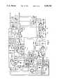
- FIG. 3is a detailed circuit diagram of the present invention.
- the voltage/tim®graph for a nickel-cadmium batteryis partially illustrated in FIG. 1. It will be noted that when the battery is fully charged, the curve is essentially flat where indicated by the numeral 10 and then begins a decrease in voltage as indicated by the numeral 8 if a charging current is continued to be applied to the battery. This decrease in battery voltage is known as the - ⁇ V characteristic of nickel-cadmium batteries. It is this characteristic that is utilized by the present invention to regulate the charging of nickel-cadmium batteries.
- FIG. 2A diagrammatic block diagram of the present invention is illustrated in FIG. 2 and is designated generally by the numeral 11.
- the circuit 11includes a charging current source 12 which includes a fast charging current circuit 13 and a slow charging current circuit 15 which are coupled through switches 17 and 19, respectively, to a nickel-cadmium battery 14.
- the fast and slow charging circuits 13 and 15 in the charging current source 12are controlled by charging control subcircuit 16, timer 18 and thermostat 20.
- Each of the subcircuits 16, 18 and 20drive an electro-optical device 22 which selectively connects and disconnects the fast charging circuit 13 and the slow charging circuit 15 to the battery 14.
- the fast charging current circuit 13is coupled through switch 17 to 30 one side of the battery 14 and to one terminal of comparator 24 in the - ⁇ V circuit 16.
- the charging currentis also coupled through a resistor 26 and capacitor 28 to the other input terminal of comparator 24.
- Diode 30 in parallel with resistor 26causes capacitor 28 to charge rapidly to within 0.6 volt of battery voltage when the fast charge is begun. This speeds the - ⁇ V circuit response if a fully-charged battery pack is inserted into the charger, thus allowing fast charge termination in one and one-half minutes typically.
- Diode 32causes rapid discharge of capacitor 28 allowing packs to be inserted into the charger in quick succession without the need for a 100-second wait for the capacitor 28 to discharge through resistor 26.
- the voltage on capacitor 28is lower than battery voltage because the battery voltage is slowly rising and the voltage on capacitor 28 is trying to "catch up".
- capacitor 28has already charged to peak battery voltage and battery voltage is beginning to descend as shown in FIG. 1 at curve portion 8.
- This conditioncauses the output of comparator 24 to change from a "high” to a “low” state which varies current flow to electro-optical device 22 and opens switch 17 and closes switch 19, thus disconnecting the fast charging circuit 13 from the battery 14 and connecting the slow charging circuit 15 to the battery 14.
- the fast charging circuit 13generates a five amp fast charge rate utilizing 13 microsecond pulses at 22 KHz as will be shown hereafter.
- the slow charging circuit 15provides 300 milliamps continuous charge rating to the ni-cad battery 14.
- a timer 18is also initiated when the battery pack is inserted in the charger 11. After a predetermined period of time, such as 18 minutes, the timer generates an output on line 34 that is used to vary the current flow to electro-optical circuit 22 and again disconnect the fast charging circuit 13 from battery 14 and connect the slow charging circuit 15 to the battery 14.
- a thermostat 20includes a high temperature thermostat 23 and a low temperature thermostat 25 (see FIG. 3). They check the temperature of the battery and, if the battery temperature is in the range of 40°-60° C., the high thermostat 23 will also generate a signal on line 21 to interrupt or vary current flow to the electro-optical device 22, again disconnecting the fast charging circuit 13 from the battery 14.
- the low temperature thermostat 25opens below 0° C. to prevent charging when battery gas recombination is slow (below 0° C.). Therefore a safe operating window of approximately 0°-45° C. is established.
- FIG. 3A detailed circuit of the novel battery charger is illustrated in FIG. 3.
- the battery charging current source 12couples the charging voltage to battery 14 on lines 36 and 38.
- the voltage on line 36is also coupled to an electro-optical circuit 22 which causes the integrated circuit 40 to generate an output on line 3 of approximately 13 microsecond pulses at 22 KHz for the fast charge. That output is coupled through transistor 42 to the Insulated Gate Field Effect Transistor (IGFET) 44 which may be a commercially available type known as IRF 830.
- IGFET 44Insulated Gate Field Effect Transistor
- IRF 830Insulated Gate Field Effect Transistor
- One of two conditionswill cause IGFET 44 to TURN-OFF. The first is a base-to-emitter voltage drop across resistor 46, that turns off transistor 48 which turns off transistor 42 and removes the input to IGFET 44 causing IGFET 44 to turn off.
- the second wayis the turn-off of transistor 50 by the expiration of the 13 microsecond charging pulse from circuit 40 which shuts IGFET 44
- This operationcauses peak current regulation of IGFET 44 drain current which, in turn, sets the filter inductor 52 average current and therefore battery-charging current.
- Transformer 54 and diode 56limit the IGFET 44 current rate of rise and maximum peak current during turn-on of IGFET 44 into a previously conducting diode 58. This reduces the switching losses of IGFET 44 and diode 58 improving reliability and lowering conducted and radiated EMI (electromagnetic induction).
- the energy storage in transformer 54 and diode 56, capacitor 59, resistor 60, capacitor 62 and diode 64provide a 6.2 volt auxiliary voltage supply needed for circuit components associated with the charging control circuit 16.
- the electro-optic circuit 22is commercially available and known as 4N35. When “on”, it establishes the fast charging current circuit 13 by providing approximately 13 microsecond pulses from integrated circuit 40 at 22 KHz on line 41. When turned “off”, the electro-optic circuit 22 establishes the slow charging current circuit 15 by causing the charging pulses to be reduced to 1.5 KHz and thus the charging rate provided by the integrated circuit 40 is greatly reduced to 50-300 milliamps to provide a slow charge.
- Integrated circuit 40may be an astable multivibrator of the commercially available type known as 555.
- charging controlis accomplished by one of three factors. The first is the characteristic - ⁇ V of the ni-cad pack at the onset of overcharge. This is accomplished by the - ⁇ V circuit 16 and associated components. The second is the expiration of the timer 18 and the third is the opening of the battery thermostat 20 at 40°-60° C. temperature of the battery. The occurrence of one or more of the above events causes the nominal five amp fast charging rate to drop to the required 50-300 milliamp continuous charge rating of the four-, six-, and ten-cell ni-cad battery packs.
- the characteristic - ⁇ V of the ni-cad pack at the onset of overchargeis detected by circuit 16.
- Raw battery voltageis filtered by resistor 66 and capacitor 67 to remove noise and ripple.
- the voltageis then applied to the non-inverting input of comparator 24 through resistor 68 directly. It is also applied to its inverting input by way of a 100-second time constant filter formed by resistor 26 and capacitor 28.
- the voltage across capacitor 28, or stored by capacitor 28is lower than battery voltage because battery voltage is slowly rising and the voltage being stored in capacitor 28 is trying to "catch up".
- capacitor 28has already charged to the peak battery voltage and battery voltage begins to descend, as illustrated in FIG. 1 at point 8 on the battery charge curve.
- comparator 24This condition causes comparator 24 to change its output from a “high” to a “low” state. This causes the output of comparator 70 to go “high” and finally causes hysteresis latch comparator 72 to go, and stay, low which shuts off transistor 74 through line 75, thus terminating current flow to the electro-optic circuit 22. This causes integrated circuit 40 to reduce the charge rate to the desired 50-300 milliamp trickle or slow rate.
- Diode 30causes capacitor 28 to charge rapidly to within 0.6 volt of battery voltage when the fast charge is begun. This speeds the - ⁇ V circuit response if a fully-charged pack is inserted into the charger, thus allowing fast charge termination in 1.5 minutes typically.
- Diode 32causes rapid discharge of capacitor C4 allowing battery packs to be inserted into the charger in quick succession without the need for a 100-second wait for capacitor 28 to discharge through resistor 26.
- comparator 72is automatically set to produce an output to cause the fast charge or "high" state through capacitor 76, resistor 78 and diode 80.
- capacitor 28attempts to "catch up” with the battery voltage. It does catch up with the battery voltage at the time the battery is fully charged.
- capacitor 28 voltagebecomes greater than the battery voltage, thus turning off the electro-optic device 22 and causing the circuit 12 to revert to the slow or trickle charge operation.
- the timer circuit 18includes an integrated digital timer circuit 82 of the commercially available type known as MC14060B which provides a back-up charge control in the event of the - ⁇ V circuit failure. This occurs when a count of 8192 is reached, thus pulling line 83 of integrated circuit 82 high, which resets comparator 72 to the "low” or slow charge state. Diode 84 terminates the clock in counter 82 at a count of 8192, thus causing line 83 of the counter 82 to remain “high” and forcing a "low” at the output of comparator 72 should a latch component fail, for instance a leaky capacitor 76, an open resistor 78 or open resistor 86.
- the digital timer 18also doubles as a means of inhibiting the - ⁇ V circuit for about 70 seconds following the start of rapid harge to prevent false - ⁇ V charge termination due to anomalous battery voltage-time characteristics in this region.
- a count of 512is extracted on line 85 of integrated circuit 82 and is used to reset latch or comparator 88 to a "low" state allowing the inverting output of comparator 70 to be driven low by the - ⁇ V circuit after a count of 512 is reached.
- Comparator 88is set automatically by capacitor 90 at the moment of battery pack insertion. Simultaneously, capacitor 92, diode 94 and resistor 96 reset integrated circuit 82 to a count of 0, thus initializing both timer functions.
- a thermostat control 20bypasses the timer, the - ⁇ V and the latch circuitry for greater reliability. It includes a high temperature thermostat 23 and a low temperature thermostat 25 in series. When the high temperature thermostat 23 opens, all current from the battery charger ceases to flow through the battery 14, preventing the battery 14 from overheating. A neon pilot lamp 106 then illuminates because of its parallel connection to the now open thermostat. This neon indicator lamp 106 is ballasted by a series connected resistor and serves to warn the user that the battery is overheated. In this way, a hot battery pack, when inserted, will not be charged until it cools sufficiently to close the thermostat 23, at which time a normal fast charge will occur.
- the low temperature thermostat 25is added in series with the high temperature (45° C.) thermostat 23. Therefore a safe operating temperature window (0°-45° C.) is established.
- a 22-volt Zener diode 100, diode 102 and capacitor 104protect both the control circuit 16 and the battery pack 14 from excess voltage due to contact bounce during pack insertion and battery dry-out, although dry-out is expected to cause rapid rise of pack temperatures and consequent thermostat activated shut-down. In operation, pack voltages in excess of 22 volts will cause reduction of charge current to less than 80 milliamps by direct removal of the forward bias to the electro-optic unit 22.
- Thermostat open indicator lamp 106is driven by transformer 54 and diode 56.
- Transistor 108along with resistors 110 and 112 and diodes 114 and 116 provide a 10-milliamp constant current source for red and green LEDs 118 and 120, respectively, to provide consistent brightness regardless of the number of cells in the inserted battery pack.
- Transistor 122disables the current source when 6.2 volts of auxiliary power is lost so all status indicator lamps remain dark when main power is interrupted.
- the circuitincludes a fast charging circuit and a slow or trickle charging circuit, both of which are controlled by three different circuits.
- the firstis a comparator circuit which compares the characteristic negative change in battery voltage at the onset of overcharge to the charging voltage and changes the charging current from fast charging to slow charging when the decrease in battery voltage occurs at the onset of overcharge.
- the secondincludes a timer that shuts off the fast charging circuit after a predetermined period of time such as 18 minutes and reverts to the slow charging circuit.
- the third circuitincludes a thermostat that checks the temperature of the battery and, in the event of overheating, stops the fast charging circuit and activates the slow charging circuit.
- the charging circuitsupplies a 13 microsecond charging pulse at the rate of 22 KHz to provide a five amp charge rate.
- the slow charging circuitprovides a 50-300 milliamp continuous charge at the rating of the ni-cad battery packs.
- the comparator circuituses a capacitor and a resistor at one input to the comparator. The comparator senses when the ni-cad battery charge voltage versus time curve becomes negative, indicating the onset of overcharge. Battery voltage is supplied to the capacitor by way of the resistor. The comparator senses the voltage across the capacitor. If the battery's voltage is increasing with time, the battery voltage is always higher than that of the capacitor, thus producing a high output from the comparator.
- the RC time constantis chosen so that the capacitor nearly fully charges to the battery voltage during the relatively flat portion of the charge curve that occurs near full charge. Therefore, when the battery voltage rapidly descends at the onset of overcharge, the capacitor voltage is higher than the battery voltage and the comparator changes state producing a low output which is used in turn to terminate the fast charge rate.
Landscapes
- Engineering & Computer Science (AREA)
- Power Engineering (AREA)
- Charge And Discharge Circuits For Batteries Or The Like (AREA)
Abstract
Description
Claims (15)
Priority Applications (1)
| Application Number | Priority Date | Filing Date | Title |
|---|---|---|---|
| US07/757,237US5196780A (en) | 1991-09-10 | 1991-09-10 | Ni-Cad battery charger circuit |
Applications Claiming Priority (1)
| Application Number | Priority Date | Filing Date | Title |
|---|---|---|---|
| US07/757,237US5196780A (en) | 1991-09-10 | 1991-09-10 | Ni-Cad battery charger circuit |
Publications (1)
| Publication Number | Publication Date |
|---|---|
| US5196780Atrue US5196780A (en) | 1993-03-23 |
Family
ID=25046973
Family Applications (1)
| Application Number | Title | Priority Date | Filing Date |
|---|---|---|---|
| US07/757,237Expired - Fee RelatedUS5196780A (en) | 1991-09-10 | 1991-09-10 | Ni-Cad battery charger circuit |
Country Status (1)
| Country | Link |
|---|---|
| US (1) | US5196780A (en) |
Cited By (22)
| Publication number | Priority date | Publication date | Assignee | Title |
|---|---|---|---|---|
| WO1995017022A1 (en)* | 1993-12-15 | 1995-06-22 | Unitrode Corporation | Battery charger circuit |
| FR2719953A1 (en)* | 1994-05-13 | 1995-11-17 | Motorola Inc | Apparatus and method for maintaining the charge of a battery. |
| US5691624A (en)* | 1995-04-24 | 1997-11-25 | Samsung Electronics Co., Ltd. | Method and apparatus for detecting a full-charge condition while charging a battery |
| US5864224A (en)* | 1994-12-26 | 1999-01-26 | Yamaha Hatsudoki Kabushiki Kaisha | Method for charging secondary battery and charger therefor |
| US6172480B1 (en)* | 1998-10-23 | 2001-01-09 | Primetech Electronics, Inc. | Compact fast battery charger |
| US20040039534A1 (en)* | 2002-08-20 | 2004-02-26 | Trembley Matthew Glen | Battery charger system and method for providing detailed battery status and charging method information |
| US6713894B1 (en)* | 1997-12-11 | 2004-03-30 | Bayerische Motoren Werke Aktiengesellschaft | Device for supplying electricity to a motor vehicle |
| US20040196005A1 (en)* | 2003-04-04 | 2004-10-07 | Sanyo Denki Co., Ltd. | Uninterruptible power supply device with circuit for degradation judgment of storage battery |
| US20050088144A1 (en)* | 2003-10-23 | 2005-04-28 | Schumacher Electric Corporation | System and method for charging batteries |
| US20060152194A1 (en)* | 2005-01-13 | 2006-07-13 | Ligong Wang | Systems and methods for regulating pre-charge current in a battery system |
| US20060181244A1 (en)* | 2005-02-16 | 2006-08-17 | Shiguo Luo | Systems and methods for integration of charger regulation within a battery system |
| US20080074080A1 (en)* | 2006-09-26 | 2008-03-27 | Shiguo Luo | Battery systems for information handling systems |
| US20080203817A1 (en)* | 2007-02-22 | 2008-08-28 | Shiguo Luo | Power architecture for battery powered remote devices |
| US20100190052A1 (en)* | 2009-01-27 | 2010-07-29 | Umesh Rajani | Battery pack with high and low current discharge terminals |
| US20110163722A1 (en)* | 2010-03-11 | 2011-07-07 | Ford Global Technologies, Llc | Vehicle and method of charging battery of same |
| US20110221392A1 (en)* | 2010-03-11 | 2011-09-15 | Ford Global Technologies, Llc | Vehicle and method of diagnosing battery condition of same |
| CN102324581A (en)* | 2011-07-22 | 2012-01-18 | 辽宁九夷三普电池有限公司 | Charging method for trickle charge or standard charge of rechargeable nickel-hydrogen storage battery |
| CN102593540A (en)* | 2012-02-17 | 2012-07-18 | 中兴通讯股份有限公司 | A battery activation method, module and terminal |
| US20140009120A1 (en)* | 2012-07-09 | 2014-01-09 | Samsung Electronics Co., Ltd. | Method for charging battery and an electronic device thereof |
| US20140028267A1 (en)* | 2012-07-26 | 2014-01-30 | Samsung Sdl Co., Ltd. | Battery charging method and battery pack utilizing the same |
| US20150340895A1 (en)* | 2014-05-20 | 2015-11-26 | Sharmila Vijay Salvi | Portable Electrical Charging Device With Timer Function |
| CN111049220A (en)* | 2019-12-25 | 2020-04-21 | 上海摩勤智能技术有限公司 | Charging circuit, terminal equipment and charging system |
Citations (18)
| Publication number | Priority date | Publication date | Assignee | Title |
|---|---|---|---|---|
| US4341988A (en)* | 1980-06-25 | 1982-07-27 | Emhart Industries, Inc. | Voltage level detector for battery charger control circuit |
| US4346336A (en)* | 1980-11-17 | 1982-08-24 | Frezzolini Electronics, Inc. | Battery control system |
| US4392101A (en)* | 1978-05-31 | 1983-07-05 | Black & Decker Inc. | Method of charging batteries and apparatus therefor |
| US4394612A (en)* | 1982-01-04 | 1983-07-19 | Skil Corporation | Battery charging circuit |
| US4395672A (en)* | 1981-04-02 | 1983-07-26 | Gassaway Lee V | Battery charger controller |
| US4413221A (en)* | 1980-12-18 | 1983-11-01 | Christie Electric Corporation | Method and circuit for determining battery capacity |
| US4639655A (en)* | 1984-04-19 | 1987-01-27 | Westhaver Lawrence A | Method and apparatus for battery charging |
| US4647834A (en)* | 1984-12-17 | 1987-03-03 | Castleman Cordell V | Battery charger |
| US4649333A (en)* | 1985-04-30 | 1987-03-10 | Levitt-Safety Limited | Two terminal nicad battery charger with battery voltage and temperature sensing |
| US4670703A (en)* | 1985-05-06 | 1987-06-02 | General Electric Company | Battery charger with three different charging rates |
| US4727306A (en)* | 1986-06-26 | 1988-02-23 | Motorola, Inc. | Portable battery charger |
| US4746854A (en)* | 1986-10-29 | 1988-05-24 | Span, Inc. | Battery charging system with microprocessor control of voltage and current monitoring and control operations |
| US4806840A (en)* | 1983-12-30 | 1989-02-21 | Alexander Manufacturing Company | Method and apparatus for charging a nickel-cadmium battery |
| US4820965A (en)* | 1987-03-23 | 1989-04-11 | Maurice A. Sween | Control circuit for battery charger |
| US4843299A (en)* | 1987-06-01 | 1989-06-27 | Power-Tech Systems Corporation | Universal battery charging system and a method |
| US4888544A (en)* | 1988-01-04 | 1989-12-19 | Motorola, Inc. | Battery charger |
| US5028859A (en)* | 1989-06-05 | 1991-07-02 | Motorola, Inc. | Multiple battery, multiple rate battery charger |
| US5057762A (en)* | 1990-07-30 | 1991-10-15 | Motorola, Inc. | System for determining battery charge states and charging sequence for a battery charger |
- 1991
- 1991-09-10USUS07/757,237patent/US5196780A/ennot_activeExpired - Fee Related
Patent Citations (18)
| Publication number | Priority date | Publication date | Assignee | Title |
|---|---|---|---|---|
| US4392101A (en)* | 1978-05-31 | 1983-07-05 | Black & Decker Inc. | Method of charging batteries and apparatus therefor |
| US4341988A (en)* | 1980-06-25 | 1982-07-27 | Emhart Industries, Inc. | Voltage level detector for battery charger control circuit |
| US4346336A (en)* | 1980-11-17 | 1982-08-24 | Frezzolini Electronics, Inc. | Battery control system |
| US4413221A (en)* | 1980-12-18 | 1983-11-01 | Christie Electric Corporation | Method and circuit for determining battery capacity |
| US4395672A (en)* | 1981-04-02 | 1983-07-26 | Gassaway Lee V | Battery charger controller |
| US4394612A (en)* | 1982-01-04 | 1983-07-19 | Skil Corporation | Battery charging circuit |
| US4806840A (en)* | 1983-12-30 | 1989-02-21 | Alexander Manufacturing Company | Method and apparatus for charging a nickel-cadmium battery |
| US4639655A (en)* | 1984-04-19 | 1987-01-27 | Westhaver Lawrence A | Method and apparatus for battery charging |
| US4647834A (en)* | 1984-12-17 | 1987-03-03 | Castleman Cordell V | Battery charger |
| US4649333A (en)* | 1985-04-30 | 1987-03-10 | Levitt-Safety Limited | Two terminal nicad battery charger with battery voltage and temperature sensing |
| US4670703A (en)* | 1985-05-06 | 1987-06-02 | General Electric Company | Battery charger with three different charging rates |
| US4727306A (en)* | 1986-06-26 | 1988-02-23 | Motorola, Inc. | Portable battery charger |
| US4746854A (en)* | 1986-10-29 | 1988-05-24 | Span, Inc. | Battery charging system with microprocessor control of voltage and current monitoring and control operations |
| US4820965A (en)* | 1987-03-23 | 1989-04-11 | Maurice A. Sween | Control circuit for battery charger |
| US4843299A (en)* | 1987-06-01 | 1989-06-27 | Power-Tech Systems Corporation | Universal battery charging system and a method |
| US4888544A (en)* | 1988-01-04 | 1989-12-19 | Motorola, Inc. | Battery charger |
| US5028859A (en)* | 1989-06-05 | 1991-07-02 | Motorola, Inc. | Multiple battery, multiple rate battery charger |
| US5057762A (en)* | 1990-07-30 | 1991-10-15 | Motorola, Inc. | System for determining battery charge states and charging sequence for a battery charger |
Cited By (40)
| Publication number | Priority date | Publication date | Assignee | Title |
|---|---|---|---|---|
| WO1995017022A1 (en)* | 1993-12-15 | 1995-06-22 | Unitrode Corporation | Battery charger circuit |
| US5504416A (en)* | 1993-12-15 | 1996-04-02 | Unitrode Corporation | Battery charger circuit including battery temperature control |
| FR2719953A1 (en)* | 1994-05-13 | 1995-11-17 | Motorola Inc | Apparatus and method for maintaining the charge of a battery. |
| ES2124670A1 (en)* | 1994-05-13 | 1999-02-01 | Motorola Inc | Apparatus and method for maintaining the charge of a battery |
| US5864224A (en)* | 1994-12-26 | 1999-01-26 | Yamaha Hatsudoki Kabushiki Kaisha | Method for charging secondary battery and charger therefor |
| US5691624A (en)* | 1995-04-24 | 1997-11-25 | Samsung Electronics Co., Ltd. | Method and apparatus for detecting a full-charge condition while charging a battery |
| US6713894B1 (en)* | 1997-12-11 | 2004-03-30 | Bayerische Motoren Werke Aktiengesellschaft | Device for supplying electricity to a motor vehicle |
| US6301132B1 (en) | 1998-10-23 | 2001-10-09 | Primetech Electronics, Inc. | Compact fast battery charger |
| US6172480B1 (en)* | 1998-10-23 | 2001-01-09 | Primetech Electronics, Inc. | Compact fast battery charger |
| US20040039534A1 (en)* | 2002-08-20 | 2004-02-26 | Trembley Matthew Glen | Battery charger system and method for providing detailed battery status and charging method information |
| US6937947B2 (en)* | 2002-08-20 | 2005-08-30 | Lsi Logic Corporation | Battery charger system and method for providing detailed battery status and charging method information |
| US20040196005A1 (en)* | 2003-04-04 | 2004-10-07 | Sanyo Denki Co., Ltd. | Uninterruptible power supply device with circuit for degradation judgment of storage battery |
| US7759822B2 (en)* | 2003-04-04 | 2010-07-20 | Sanyo Denki Co., Ltd. | Uninterruptible power supply device with circuit for degradation judgment of storage battery |
| US20100013316A1 (en)* | 2003-04-04 | 2010-01-21 | Sanyo Denki Co., Ltd. | Uninterruptible power supply device with circuit for degradation judgment of storage battery |
| US7612468B2 (en)* | 2003-04-04 | 2009-11-03 | Sanyo Denki Co., Ltd. | Uninterruptible power supply device with circuit for degradation judgment of storage battery |
| US7528579B2 (en) | 2003-10-23 | 2009-05-05 | Schumacher Electric Corporation | System and method for charging batteries |
| US20090206796A1 (en)* | 2003-10-23 | 2009-08-20 | Pacholok David R | System and method for charging batteries |
| US20050088144A1 (en)* | 2003-10-23 | 2005-04-28 | Schumacher Electric Corporation | System and method for charging batteries |
| US7808211B2 (en) | 2003-10-23 | 2010-10-05 | Schumacher Electric Corporation | System and method for charging batteries |
| US7378819B2 (en) | 2005-01-13 | 2008-05-27 | Dell Products Lp | Systems and methods for regulating pulsed pre-charge current in a battery system |
| US20060152194A1 (en)* | 2005-01-13 | 2006-07-13 | Ligong Wang | Systems and methods for regulating pre-charge current in a battery system |
| US7391184B2 (en) | 2005-02-16 | 2008-06-24 | Dell Products L.P. | Systems and methods for integration of charger regulation within a battery system |
| US20060181244A1 (en)* | 2005-02-16 | 2006-08-17 | Shiguo Luo | Systems and methods for integration of charger regulation within a battery system |
| US7436149B2 (en) | 2006-09-26 | 2008-10-14 | Dell Products L.P. | Systems and methods for interfacing a battery-powered information handling system with a battery pack of a physically separable battery-powered input or input/output device |
| US20080074080A1 (en)* | 2006-09-26 | 2008-03-27 | Shiguo Luo | Battery systems for information handling systems |
| US20080203817A1 (en)* | 2007-02-22 | 2008-08-28 | Shiguo Luo | Power architecture for battery powered remote devices |
| US20100190052A1 (en)* | 2009-01-27 | 2010-07-29 | Umesh Rajani | Battery pack with high and low current discharge terminals |
| US20110221392A1 (en)* | 2010-03-11 | 2011-09-15 | Ford Global Technologies, Llc | Vehicle and method of diagnosing battery condition of same |
| US20110163722A1 (en)* | 2010-03-11 | 2011-07-07 | Ford Global Technologies, Llc | Vehicle and method of charging battery of same |
| US8947050B2 (en)* | 2010-03-11 | 2015-02-03 | Ford Global Technologies, Llc | Charging of vehicle battery based on indicators of impedance and health |
| US9753093B2 (en) | 2010-03-11 | 2017-09-05 | Ford Global Technologies, Llc | Vehicle and method of diagnosing battery condition of same |
| CN102324581A (en)* | 2011-07-22 | 2012-01-18 | 辽宁九夷三普电池有限公司 | Charging method for trickle charge or standard charge of rechargeable nickel-hydrogen storage battery |
| CN102593540A (en)* | 2012-02-17 | 2012-07-18 | 中兴通讯股份有限公司 | A battery activation method, module and terminal |
| CN102593540B (en)* | 2012-02-17 | 2015-08-12 | 中兴通讯股份有限公司 | A kind of battery activated method, module and terminal |
| US20140009120A1 (en)* | 2012-07-09 | 2014-01-09 | Samsung Electronics Co., Ltd. | Method for charging battery and an electronic device thereof |
| US9728989B2 (en)* | 2012-07-09 | 2017-08-08 | Samsung Electronics Co., Ltd. | Method for charging battery inside electronic device with a plurality of power supplies and a plurality of charging modules with USB OTG functionality |
| US20140028267A1 (en)* | 2012-07-26 | 2014-01-30 | Samsung Sdl Co., Ltd. | Battery charging method and battery pack utilizing the same |
| US9312712B2 (en)* | 2012-07-26 | 2016-04-12 | Samsung Sdi Co., Ltd. | Method and system for controlling charging parameters of a battery using a plurality of temperature ranges and counters and parameter sets |
| US20150340895A1 (en)* | 2014-05-20 | 2015-11-26 | Sharmila Vijay Salvi | Portable Electrical Charging Device With Timer Function |
| CN111049220A (en)* | 2019-12-25 | 2020-04-21 | 上海摩勤智能技术有限公司 | Charging circuit, terminal equipment and charging system |
Similar Documents
| Publication | Publication Date | Title |
|---|---|---|
| US5196780A (en) | Ni-Cad battery charger circuit | |
| US4554500A (en) | Battery charging apparatus and method | |
| US4727306A (en) | Portable battery charger | |
| US5736833A (en) | Rapid battery charging circuit with overvoltage shunt | |
| US5480734A (en) | Rechargeable accumulator | |
| US5250891A (en) | Battery charging method and apparatus | |
| US4468605A (en) | Timed voltage clamp for battery charger | |
| EP0479248B1 (en) | Quick charge control apparatus and control method thereof | |
| EP0440756B1 (en) | Battery assembly and charging system | |
| EP0479249B1 (en) | Charge control apparatus for use with electronic equipment | |
| CN101604861B (en) | Battery charging control circuit and charger | |
| CN100514742C (en) | Battery charging method | |
| US5321347A (en) | Battery charger device and method | |
| CN1334630A (en) | Shunt voltage regulator with self-contained safety heat short-circuit protection | |
| KR20180050960A (en) | The battery pack and a vacuum cleaner including the same | |
| US4383212A (en) | Battery charger control device with D-C disconnect and A-C interrupt | |
| US7227337B2 (en) | Battery charger with dual use microprocessor | |
| US5767657A (en) | Battery charger having a battery discharge prevention circuit | |
| JPH07298504A (en) | Charging method for secondary battery | |
| CN100416976C (en) | Charging apparatus | |
| US11349325B2 (en) | Temperature dependent current and pulse controlled charging method for a battery charger | |
| JPH05199674A (en) | Method for charging battery | |
| JPH04145841A (en) | Rapid charging system | |
| JPH0614474A (en) | Charging apparatus | |
| CN211180588U (en) | Control circuit applied to face cleaning tool |
Legal Events
| Date | Code | Title | Description |
|---|---|---|---|
| FEPP | Fee payment procedure | Free format text:PAYOR NUMBER ASSIGNED (ORIGINAL EVENT CODE: ASPN); ENTITY STATUS OF PATENT OWNER: LARGE ENTITY | |
| FPAY | Fee payment | Year of fee payment:4 | |
| FPAY | Fee payment | Year of fee payment:8 | |
| FEPP | Fee payment procedure | Free format text:PAYOR NUMBER ASSIGNED (ORIGINAL EVENT CODE: ASPN); ENTITY STATUS OF PATENT OWNER: LARGE ENTITY Free format text:PAYER NUMBER DE-ASSIGNED (ORIGINAL EVENT CODE: RMPN); ENTITY STATUS OF PATENT OWNER: LARGE ENTITY | |
| FEPP | Fee payment procedure | Free format text:PAYOR NUMBER ASSIGNED (ORIGINAL EVENT CODE: ASPN); ENTITY STATUS OF PATENT OWNER: LARGE ENTITY Free format text:PAYER NUMBER DE-ASSIGNED (ORIGINAL EVENT CODE: RMPN); ENTITY STATUS OF PATENT OWNER: LARGE ENTITY | |
| REMI | Maintenance fee reminder mailed | ||
| FEPP | Fee payment procedure | Free format text:PAYER NUMBER DE-ASSIGNED (ORIGINAL EVENT CODE: RMPN); ENTITY STATUS OF PATENT OWNER: LARGE ENTITY Free format text:PAYOR NUMBER ASSIGNED (ORIGINAL EVENT CODE: ASPN); ENTITY STATUS OF PATENT OWNER: LARGE ENTITY | |
| LAPS | Lapse for failure to pay maintenance fees | ||
| STCH | Information on status: patent discontinuation | Free format text:PATENT EXPIRED DUE TO NONPAYMENT OF MAINTENANCE FEES UNDER 37 CFR 1.362 | |
| FP | Lapsed due to failure to pay maintenance fee | Effective date:20050323 |