US5196004A - Infrared laser catheter system - Google Patents
Infrared laser catheter systemDownload PDFInfo
- Publication number
- US5196004A US5196004AUS07/427,251US42725189AUS5196004AUS 5196004 AUS5196004 AUS 5196004AUS 42725189 AUS42725189 AUS 42725189AUS 5196004 AUS5196004 AUS 5196004A
- Authority
- US
- United States
- Prior art keywords
- optical fiber
- laser energy
- laser
- energy source
- surgical site
- Prior art date
- Legal status (The legal status is an assumption and is not a legal conclusion. Google has not performed a legal analysis and makes no representation as to the accuracy of the status listed.)
- Expired - Lifetime
Links
- 239000013307optical fiberSubstances0.000claimsabstractdescription107
- 208000037260Atherosclerotic PlaqueDiseases0.000claimsabstractdescription40
- VYPSYNLAJGMNEJ-UHFFFAOYSA-NSilicium dioxideChemical compoundO=[Si]=OVYPSYNLAJGMNEJ-UHFFFAOYSA-N0.000claimsabstractdescription17
- 239000002223garnetSubstances0.000claimsabstractdescription6
- 239000000377silicon dioxideSubstances0.000claimsabstractdescription6
- XLYOFNOQVPJJNP-UHFFFAOYSA-MhydroxideChemical compound[OH-]XLYOFNOQVPJJNP-UHFFFAOYSA-M0.000claimsabstractdescription4
- HIQSCMNRKRMPJT-UHFFFAOYSA-Jlithium;yttrium(3+);tetrafluorideChemical compound[Li+].[F-].[F-].[F-].[F-].[Y+3]HIQSCMNRKRMPJT-UHFFFAOYSA-J0.000claimsabstractdescription4
- 239000000835fiberSubstances0.000claimsdescription67
- 238000009834vaporizationMethods0.000claimsdescription14
- 230000008016vaporizationEffects0.000claimsdescription14
- 238000000034methodMethods0.000claimsdescription10
- 230000003287optical effectEffects0.000claimsdescription9
- 230000005540biological transmissionEffects0.000claimsdescription4
- 230000001902propagating effectEffects0.000claims4
- 230000008878couplingEffects0.000claims1
- 238000010168coupling processMethods0.000claims1
- 238000005859coupling reactionMethods0.000claims1
- JNDMLEXHDPKVFC-UHFFFAOYSA-Naluminum;oxygen(2-);yttrium(3+)Chemical compound[O-2].[O-2].[O-2].[Al+3].[Y+3]JNDMLEXHDPKVFC-UHFFFAOYSA-N0.000abstractdescription14
- 229910019901yttrium aluminum garnetInorganic materials0.000abstractdescription14
- 230000008439repair processEffects0.000abstractdescription6
- 229910019655synthetic inorganic crystalline materialInorganic materials0.000abstract3
- 238000010521absorption reactionMethods0.000description37
- 239000000523sampleSubstances0.000description26
- XLYOFNOQVPJJNP-UHFFFAOYSA-NwaterSubstancesOXLYOFNOQVPJJNP-UHFFFAOYSA-N0.000description22
- CURLTUGMZLYLDI-UHFFFAOYSA-NCarbon dioxideChemical compoundO=C=OCURLTUGMZLYLDI-UHFFFAOYSA-N0.000description17
- 229910002092carbon dioxideInorganic materials0.000description13
- 239000000463materialSubstances0.000description13
- 239000008280bloodSubstances0.000description11
- 210000004369bloodAnatomy0.000description11
- 239000013078crystalSubstances0.000description11
- 238000002474experimental methodMethods0.000description11
- 230000002308calcificationEffects0.000description9
- 238000010586diagramMethods0.000description8
- 239000011521glassSubstances0.000description7
- 238000001356surgical procedureMethods0.000description7
- 238000010276constructionMethods0.000description6
- 230000006378damageEffects0.000description6
- 239000010980sapphireSubstances0.000description6
- 229910052594sapphireInorganic materials0.000description6
- 230000003685thermal hair damageEffects0.000description6
- 210000001367arteryAnatomy0.000description5
- 230000007480spreadingEffects0.000description5
- 238000003892spreadingMethods0.000description5
- XKRFYHLGVUSROY-UHFFFAOYSA-NArgonChemical compound[Ar]XKRFYHLGVUSROY-UHFFFAOYSA-N0.000description4
- IJGRMHOSHXDMSA-UHFFFAOYSA-NAtomic nitrogenChemical compoundN#NIJGRMHOSHXDMSA-UHFFFAOYSA-N0.000description4
- 102000001554HemoglobinsHuman genes0.000description4
- 108010054147HemoglobinsProteins0.000description4
- 239000001569carbon dioxideSubstances0.000description4
- 238000009792diffusion processMethods0.000description4
- 238000009826distributionMethods0.000description4
- 239000007789gasSubstances0.000description4
- 239000000203mixtureSubstances0.000description4
- 238000012421spikingMethods0.000description4
- FAPWRFPIFSIZLT-UHFFFAOYSA-MSodium chlorideChemical compound[Na+].[Cl-]FAPWRFPIFSIZLT-UHFFFAOYSA-M0.000description3
- 238000002679ablationMethods0.000description3
- 239000012620biological materialSubstances0.000description3
- UGFAIRIUMAVXCW-UHFFFAOYSA-NCarbon monoxideChemical compound[O+]#[C-]UGFAIRIUMAVXCW-UHFFFAOYSA-N0.000description2
- 229910052691ErbiumInorganic materials0.000description2
- MARDFMMXBWIRTK-UHFFFAOYSA-N[F].[Ar]Chemical compound[F].[Ar]MARDFMMXBWIRTK-UHFFFAOYSA-N0.000description2
- VFQHLZMKZVVGFQ-UHFFFAOYSA-N[F].[Kr]Chemical compound[F].[Kr]VFQHLZMKZVVGFQ-UHFFFAOYSA-N0.000description2
- JWFFDNVGFHXGIB-UHFFFAOYSA-N[F].[Xe]Chemical compound[F].[Xe]JWFFDNVGFHXGIB-UHFFFAOYSA-N0.000description2
- 229910052786argonInorganic materials0.000description2
- 229910002091carbon monoxideInorganic materials0.000description2
- 238000001816coolingMethods0.000description2
- 238000005520cutting processMethods0.000description2
- UYAHIZSMUZPPFV-UHFFFAOYSA-NerbiumChemical compound[Er]UYAHIZSMUZPPFV-UHFFFAOYSA-N0.000description2
- 239000012530fluidSubstances0.000description2
- 238000011010flushing procedureMethods0.000description2
- 239000005350fused silica glassSubstances0.000description2
- CPBQJMYROZQQJC-UHFFFAOYSA-Nhelium neonChemical compound[He].[Ne]CPBQJMYROZQQJC-UHFFFAOYSA-N0.000description2
- 238000000338in vitroMethods0.000description2
- 238000002430laser surgeryMethods0.000description2
- 239000007788liquidSubstances0.000description2
- 229910052757nitrogenInorganic materials0.000description2
- BASFCYQUMIYNBI-UHFFFAOYSA-NplatinumChemical compound[Pt]BASFCYQUMIYNBI-UHFFFAOYSA-N0.000description2
- 102000004169proteins and genesHuman genes0.000description2
- 108090000623proteins and genesProteins0.000description2
- 238000005086pumpingMethods0.000description2
- 239000010453quartzSubstances0.000description2
- 238000002310reflectometryMethods0.000description2
- 239000007787solidSubstances0.000description2
- 238000012360testing methodMethods0.000description2
- 210000003462veinAnatomy0.000description2
- RZVAJINKPMORJF-UHFFFAOYSA-NAcetaminophenChemical compoundCC(=O)NC1=CC=C(O)C=C1RZVAJINKPMORJF-UHFFFAOYSA-N0.000description1
- OKTJSMMVPCPJKN-UHFFFAOYSA-NCarbonChemical compound[C]OKTJSMMVPCPJKN-UHFFFAOYSA-N0.000description1
- 239000004809TeflonSubstances0.000description1
- 229920006362Teflon®Polymers0.000description1
- 230000002411adverseEffects0.000description1
- 229910052782aluminiumInorganic materials0.000description1
- XAGFODPZIPBFFR-UHFFFAOYSA-NaluminiumChemical compound[Al]XAGFODPZIPBFFR-UHFFFAOYSA-N0.000description1
- 238000002399angioplastyMethods0.000description1
- 210000000709aortaAnatomy0.000description1
- 235000013405beerNutrition0.000description1
- 238000009530blood pressure measurementMethods0.000description1
- 210000004204blood vesselAnatomy0.000description1
- 229910052799carbonInorganic materials0.000description1
- 238000003763carbonizationMethods0.000description1
- 238000013172carotid endarterectomyMethods0.000description1
- 239000000919ceramicSubstances0.000description1
- 238000005253claddingMethods0.000description1
- 230000015271coagulationEffects0.000description1
- 238000005345coagulationMethods0.000description1
- 210000001072colonAnatomy0.000description1
- 239000012141concentrateSubstances0.000description1
- 238000009833condensationMethods0.000description1
- 230000005494condensationEffects0.000description1
- 239000002826coolantSubstances0.000description1
- 230000007547defectEffects0.000description1
- 238000005553drillingMethods0.000description1
- 229920006332epoxy adhesivePolymers0.000description1
- 229920006333epoxy cementPolymers0.000description1
- 230000005284excitationEffects0.000description1
- 230000002349favourable effectEffects0.000description1
- 239000002657fibrous materialSubstances0.000description1
- 239000000945fillerSubstances0.000description1
- 239000013305flexible fiberSubstances0.000description1
- 238000007710freezingMethods0.000description1
- 230000008014freezingEffects0.000description1
- 238000000227grindingMethods0.000description1
- 125000002887hydroxy groupChemical group[H]O*0.000description1
- 238000007654immersionMethods0.000description1
- 238000001727in vivoMethods0.000description1
- 208000014674injuryDiseases0.000description1
- 238000003780insertionMethods0.000description1
- 230000037431insertionEffects0.000description1
- 238000009413insulationMethods0.000description1
- 230000002452interceptive effectEffects0.000description1
- 150000002500ionsChemical class0.000description1
- 230000001678irradiating effectEffects0.000description1
- 238000005259measurementMethods0.000description1
- 229910052751metalInorganic materials0.000description1
- 239000002184metalSubstances0.000description1
- 150000002739metalsChemical class0.000description1
- 238000012986modificationMethods0.000description1
- 230000004048modificationEffects0.000description1
- 231100000252nontoxicToxicity0.000description1
- 230000003000nontoxic effectEffects0.000description1
- 239000004033plasticSubstances0.000description1
- 229910052697platinumInorganic materials0.000description1
- -1polytetrafluoroethylenePolymers0.000description1
- 229920001343polytetrafluoroethylenePolymers0.000description1
- 239000004810polytetrafluoroethyleneSubstances0.000description1
- 230000008569processEffects0.000description1
- 239000005297pyrexSubstances0.000description1
- 230000005855radiationEffects0.000description1
- 230000002207retinal effectEffects0.000description1
- 229910052709silverInorganic materials0.000description1
- 239000004332silverSubstances0.000description1
- 238000001228spectrumMethods0.000description1
- 229910001220stainless steelInorganic materials0.000description1
- 239000010935stainless steelSubstances0.000description1
- 210000002784stomachAnatomy0.000description1
- 239000000126substanceSubstances0.000description1
- BFKJFAAPBSQJPD-UHFFFAOYSA-NtetrafluoroetheneChemical compoundFC(F)=C(F)FBFKJFAAPBSQJPD-UHFFFAOYSA-N0.000description1
- 238000010257thawingMethods0.000description1
- 230000000451tissue damageEffects0.000description1
- 231100000827tissue damageToxicity0.000description1
- 230000017423tissue regenerationEffects0.000description1
- 231100000331toxicToxicity0.000description1
- 230000002588toxic effectEffects0.000description1
- 238000012546transferMethods0.000description1
- 230000007704transitionEffects0.000description1
- 230000008733traumaEffects0.000description1
- 210000005166vasculatureAnatomy0.000description1
- 238000003466weldingMethods0.000description1
- 229910052724xenonInorganic materials0.000description1
- FHNFHKCVQCLJFQ-UHFFFAOYSA-Nxenon atomChemical compound[Xe]FHNFHKCVQCLJFQ-UHFFFAOYSA-N0.000description1
Images


Classifications
- A—HUMAN NECESSITIES
- A61—MEDICAL OR VETERINARY SCIENCE; HYGIENE
- A61B—DIAGNOSIS; SURGERY; IDENTIFICATION
- A61B18/00—Surgical instruments, devices or methods for transferring non-mechanical forms of energy to or from the body
- A61B18/18—Surgical instruments, devices or methods for transferring non-mechanical forms of energy to or from the body by applying electromagnetic radiation, e.g. microwaves
- A61B18/20—Surgical instruments, devices or methods for transferring non-mechanical forms of energy to or from the body by applying electromagnetic radiation, e.g. microwaves using laser
- A61B18/22—Surgical instruments, devices or methods for transferring non-mechanical forms of energy to or from the body by applying electromagnetic radiation, e.g. microwaves using laser the beam being directed along or through a flexible conduit, e.g. an optical fibre; Couplings or hand-pieces therefor
- A61B18/24—Surgical instruments, devices or methods for transferring non-mechanical forms of energy to or from the body by applying electromagnetic radiation, e.g. microwaves using laser the beam being directed along or through a flexible conduit, e.g. an optical fibre; Couplings or hand-pieces therefor with a catheter
- G—PHYSICS
- G02—OPTICS
- G02B—OPTICAL ELEMENTS, SYSTEMS OR APPARATUS
- G02B6/00—Light guides; Structural details of arrangements comprising light guides and other optical elements, e.g. couplings
- G02B6/24—Coupling light guides
- G02B6/42—Coupling light guides with opto-electronic elements
- G02B6/4296—Coupling light guides with opto-electronic elements coupling with sources of high radiant energy, e.g. high power lasers, high temperature light sources
- A—HUMAN NECESSITIES
- A61—MEDICAL OR VETERINARY SCIENCE; HYGIENE
- A61B—DIAGNOSIS; SURGERY; IDENTIFICATION
- A61B18/00—Surgical instruments, devices or methods for transferring non-mechanical forms of energy to or from the body
- A61B18/18—Surgical instruments, devices or methods for transferring non-mechanical forms of energy to or from the body by applying electromagnetic radiation, e.g. microwaves
- A61B18/20—Surgical instruments, devices or methods for transferring non-mechanical forms of energy to or from the body by applying electromagnetic radiation, e.g. microwaves using laser
- A61B2018/2065—Multiwave; Wavelength mixing, e.g. using four or more wavelengths
- A—HUMAN NECESSITIES
- A61—MEDICAL OR VETERINARY SCIENCE; HYGIENE
- A61B—DIAGNOSIS; SURGERY; IDENTIFICATION
- A61B90/00—Instruments, implements or accessories specially adapted for surgery or diagnosis and not covered by any of the groups A61B1/00 - A61B50/00, e.g. for luxation treatment or for protecting wound edges
- A61B90/39—Markers, e.g. radio-opaque or breast lesions markers
Definitions
- This inventionrelates to laser catheters and optical fiber systems for generating and transmitting energy to a surgical site in a living body for the purposes of tissue removal or repair
- lasershave been used for many years for industrial purposes such as drilling and cutting materials, it is only recently that surgeons have begin to use lasers for surgical operations on living tissue. To this end, laser energy has been used to repair retinal tissue and to cauterize blood vessels in the stomach and colon.
- the optical fibercan be included in a catheter which can be inserted into the body through a small opening, thus reducing the surgical trauma associated with the operation.
- the cathetercan often be maneuvered to surgical sites which are so restricted that conventional scalpel surgery is difficult, if not impossible.
- laser energycan be used to remove atherosclerotic plaque from the walls of the vasculature and to repair defects in small-diameter artery walls.
- a laser which is conventionally used for scientific purposesis an excimer laser which is a gas laser that operates with a gas mixture such as Argon-Fluorine, Krypton-Fluorine or Xenon-Fluorine.
- a gas laserthat operates with a gas mixture such as Argon-Fluorine, Krypton-Fluorine or Xenon-Fluorine.
- Another common industrial laseris the carbon dioxide or CO 2 laser.
- excimer lasersBoth the excimer laser and the CO 2 laser have been used for surgical purposes with varying results.
- One problem with excimer lasersis that they produce output energy having a wavelength in the range 0.2-0.5 micrometers. Blood hemoglobin and proteins have a relatively high absorption of energy in this wavelength range and, thus, the output beam of an excimer laser has a very short absorption length in these materials (the absorption length is the distance in the materials over which the laser beam can travel before most of the energy is absorbed).
- the surgical site in which these lasers are to be usedmust be cleared of blood prior to the operation, otherwise most of the laser energy will be absorbed by intervening blood before it reaches the surgical area. While the removal of blood is possible if surgery is performed on an open area it is often difficult if surgery is to be performed via a catheter located in an artery or vein.
- the CO 2generates output energy with a wavelength on the order of 10 micrometers. At this wavelength, the absorption of blood hemoglobin is negligible but the absorption by water and tissue is relatively high. Scattering at this wavelength is also very low. Although these characteristics of the CO 2 laser are favorable for surgical applications, the CO 2 laser suffers from the same drawback as excimer lasers in that the absorption length is relatively short due to the high absorption of the laser energy in water. Thus, the surgical area must be cleared of blood prior to the operation.
- the CO 2 laseralso suffers from a serious additional problem. Due to the long wavelength, the output energy from the carbon dioxide laser cannot be presently transmitted down any optical fibers which are suitable for use in percutaneous surgery (present fibers which can transmit energy from a CO 2 laser are either composed of toxic materials, are soluble in water or are not readily bendable, or possess a combination of the previous problems) and, thus, the laser is only suitable for operations in which the laser energy can be either applied directly to the surgical area or applied by means of an optical system comprised of prisms or mirrors.
- a laser catheter systememploys a laser source operating in the wavelength region of 1.4-2.2 micrometers.
- Illustrative laser sources operating this regionare Holmium-doped YAG, Holmium-doped YLF, Holmium-doped YSGG, Erbium-doped YAG, Erbium-doped YLF and Thulium-doped YAG lasers.
- the above-noted lasersare used with a specially-treated silica fiber that has been purified to reduce the concentration of hydroxyl (OH--) ions.
- the laser sourcemay be operated in a pulsed mode with a relatively long pulse of approximately 0.2-5 milliseconds at an energy level of approximately 1-2 joules per pulse, for a spot size of the order of 1.5 millimeters in diameter.
- the peak power of the laser pulseis approximately 1 kilowatt. This amount of power can easily be tolerated by the silica fiber, but is sufficient for rapid material removal.
- the average power delivered to a surgical site by such a laserwill be under 10 watts.
- a Holmium-doped laser sourceoperating in a pulsed mode in a wavelength range of from about 1.90 to about 2.10 micrometers, and at a threshold energy density of at least about 0.6 joules/mm 2 .
- the pulse width usedshould be substantially less than a thermal time constant for plaque, or substantially less than about 83 milliseconds.
- the repetition ratetypically is about 2 Hertz.
- the laser sourcecan be operated in a low power continuous wave mode to repair, by coagulation, of tissue by a process similar to "spot welding".
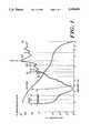
- FIG. 1shows a sketch of absorption of electromagnetic energy versus wavelength and electromagnetic energy scattering versus wavelength.
- FIG. 2shows an absorption versus wavelength plot for atherosclerotic plaque obtained in a carotid endarterectomy with the region of interest for the inventive laser sources (1.4-2.2 micrometers) outlined.
- FIG. 3 of the drawingis a schematic diagram of a typical solid state laser construction used in the inventive laser sources.
- FIG. 4 of the drawingis a plot of laser output intensity versus time for a typical pulse shape developed by a laser shown in FIG. 3 when used for tissue removal.
- FIG. 5is a schematic diagram of a laser catheter which employs a single optical fiber for transmitting laser energy to a surgical location.
- FIG. 6 of the drawingis an enlarged cross-section of the probe tip the single fiber catheter shown in FIG. 5.
- FIG. 7is an exploded view of a portion of the enlarged cross-section of the probe tip shown in FIG. 6.
- FIG. 8is a schematic diagram of a wire-guided catheter which employs four optical fibers to increase the area which can be irradiated with the laser light.
- FIG. 9 of the drawingis an enlarged cross-sectional view of the probe tip of the catheter shown in FIG. 7 showing the four optical fibers.
- FIG. 10is an end view of the probe tip of the catheter in the direction 10--10 of FIG. 9.
- FIGS. 11, 11A, 11B, and 11Care schematic diagrams of the beam pattern producted by the four-fiber catheter at the surgical location.
- FIG. 12is a schematic diagram illustrating the apparatus used to obtain in vitro data relating to the removal of atherosclerotic plaque.
- FIG. 1has a logarithmic scale representing the absorption coefficient in units of cm -1 along the vertical axis and the incident energy wavelength in micrometers along the horizontal axis.
- excimer laser systemswhich utilize conventional gas mixtures, such as Argon-Fluorine, Krypton-Fluorine and Xenon-Fluorine, and Argon gas lasers produce output energy which falls in the 0.2-0.5 micrometer wavelength region.
- gas mixturessuch as Argon-Fluorine, Krypton-Fluorine and Xenon-Fluorine
- Argon gas lasersproduce output energy which falls in the 0.2-0.5 micrometer wavelength region.
- the absorption of blood hemoglobin and proteinsis very high.
- the absorption lengthis very short (about 5-10 microns) and virtually no blood can be present between the fiber end and the surgical site during the operation. Thus, it is necessary to remove blood from the surgical area when these lasers are used for surgical purposes.
- the absorption of waterreaches a minimum at 0.5 micrometers so that it is necessary to use a higher power laser than is desirable to achieve sufficient power in the surgical area for material cutting and removal.
- the absorption lengthis very long (approximately 1 mm).
- scattering for these lasersis relatively high, causing difficulty in controlling the laser energy and a danger of tissue damage outside the surgical area due to scattering of the laser energy.
- laser sources of interestare those that lie in the wavelength range of approximately 1.4-2.15 micrometers. As shown in FIG. 1, in this range, the energy absorption of water is relatively high whereas optical scattering is relatively low.
- Illustrative lasers which are useful with the present inventioncomprise Erbium-doped Yttrium Aluminum Garnet (YAG) with a wavelength of 1.55 micrometers, Erbium-doped Yttrium Lithium Fluoride (YLF) with a wavelength of 1.73 micrometers, Thulium-doped YAG with a wavelength of 1.88 micrometers, Holmium-doped YLF with a wavelength of 2.06 micrometers, Holmium-doped YAG at a wavelength of 2.1 micrometers, and Holmium-doped Yttrium-Scandium-Gadolinium-Garnet (YSGG) at a wavelength of 2.088 micrometers.
- YAGErbium-doped Yttrium Aluminum Gar
- the absorption of the laser energy produced by lasers in this latter group by wateris moderately high and, conseguently, the absorption by biological tissues of such energy will also be relatively high.
- the absorption by wateris not as high as the absorption of CO and CO 2 laser energy.
- the absorption lengthwill be longer for the lasers operating in the 1.4-2.2 micrometer range than for CO 2 lasers.
- the absorption length in the body for lasers operating in the 1.4-2.2 micrometer rangeis about 200 microns. Therefore, it is still possible to operate satisfactorily even with 10-30 microns of blood between the fiber end and the surgical site.
- FIG. 2is a plot of the absorption by plaque of electromagnetic energy versus wavelength for energy in the wavelength range of 0.2-2.2 micrometers. As shown in FIG. 2, the absorption by plaque of electromagnetic energy reaches a minimum in the 0.8-1 micrometer wavelength range and generally increases with increasing wavelength in the wavelength region of 1-2.2 micrometers. In the wavelength range from 1.4-2.2 micrometers, the wavelength range produced by laser in the above-mentioned group, the absorption by plaque is at a relatively high value.
- FIG. 3A schematic diagram of a typical solid-state laser construction is shown in FIG. 3.
- the laser assemblyconsists of a laser crystal 1 and an excitation device such as a flashlamp 3.
- the laser crystalmust be cooled to cryogenic temperatures to provide low laser-threshhold operation.
- Cryogenic coolingis typically provided by enclosing crystal 1 in a quartz or fused-silica jacket 4 through which liquid nitrogen is circulated.
- Liquid nitrogenenters jacket 4 by means of an inlet pipe 5 and leaves by means of an outlet pipe 6.
- the laser cavityis formed by a high-reflectivity concave mirror 10 and a partial reflector 12.
- the crystalis excited by optical pumping which is, in turn, accomplished by irradiating the crystal with light from a flashlamp 3.
- a flashlamp which is typically used with the inventive laser compositionsis a high-pressure Xenon flashlamp.
- Lamp 3may also be surrounded by a quartz flow tube (not shown) through which coolant is pumped.
- Crystal 1 and flashlamp 3are enclosed in a reflector 2 which concentrates the flashlamp energy into the laser crystal.
- the inner surface of reflector 2is coated with a material chosen to have high-reflectivity at the pumping wavelength of the laser crystal--illustratively, aluminum or silver.
- a material chosen to have high-reflectivity at the pumping wavelength of the laser crystal--illustratively, aluminum or silverIn order to provide thermal insulation to prevent condensation on the system optics, it may be necessary to evacuate the interior of reflector 2 or to provide a vacuum jacket around crystal 1.
- cryogenic solid-state lasersare conventional and described in a variety of sources; accordingly such construction will not be discussed further in detail herein.
- a more complete discussion of construction details of a typical cryogenic laseris set forth in an article entitled "TEM oo Mode Ho:YLF laser", N. P. Barnes, D. J. Gettemy, N. J. Levinos and J. E. Griggs, Society of Photo Optical Instrumentation Engineers, Volume 190--LASL Conference on Optics 1979, pp 297-304.
- FIG. 4 of the drawingis a plot of the illustrative pulse shape developed by a laser in the preferred group when used in the "material removal” mode.
- FIG. 4shows light intensity along the vertical axis increasing in the downward direction versus time increasing towards the right.
- the laser sourcehas been adjusted to produce an output pulse of relatively long time duration, most of the output energy is released within approximately 1 millisecond of the beginning of the pulse.
- lasers in the preferred laser groupexhibit a "spiking” phenomenon caused by internal relaxation-oscillations in the laser crystal.
- the spiking behaviorcauses local increases in laser intensity which have a large magnitude, but a very short time duration. Similar "spiking" behavior has been found advantageous when lasers are used to drill metals and other materials for industrial purposes and it is believed that such "spiking" behavior enhances the laser usefulness for biological material removal.
- FIG. 5is a schematic diagram of a laser/catheter system employing a solid state laser of the type shown in detail in FIG. 3. More specifically, the infrared output energy of laser 21 is focused by a conventional focusing lens onto the end of the optical fiber which is held in a conventional fiber optic connector 24. Fiber optic connector 24 is, in turn, connected to a tube 27 which houses a single optical fiber. Tube 27 is connected to a conventional two-lumen catheter 30 by means of a bifurcation fitting 28.
- catheter 30has two lumens passing axially therethrough to its distal end 34 so that an optical fiber can pass through one lumen and transmit laser energy from fiber optic connector 24 to lens tip 34.
- the optical fiber which passes through the catheteris specially purified to reduce the hydroxyl ion concentration to a low level, thus preventing the laser energy which is transmitted down the fiber from being highly absorbed in the fiber material.
- a fiber which is suitable for use with the illustrative embodimentis a fused-silica optical fiber part no. 822W manufactured by the Spectran Corporation located in Sturbridge, Mass.
- the mirrors and lenses (10, 12 and 22) which are used to form the IR laser cavity and focus the output energy beamare generally only reflective to energy with a wavelength falling within a narrow wavelength band and transparent to energy at other wavelengths. Conseguently, the mirrors and lenses are transparent to visible light.
- An aiming laser 20(for example, a conventional helium-neon laser) which generates visible light may be placed in series with IR laser 21 to generate a visible light beam. This light beam may be used to align mirrors 10 and 12 and to adjust focussing lens 22 so that the optical fiber system can be aligned prior to performing surgery.
- the optical fibers used to transmit the IR energy from laser 21 to the surgical areacan also be used to transmit the visible light from the aiming laser 20 to the surgical area.
- the light produced by laser 20passes through the optical fiber in catheter 30 and can be used to aim the probe tip before laser 21 is turned on to perform the actual operation.
- the second lumen in catheter 30is provided for transmission of a flushing fluid or to apply suction to the probe lens tip area to clear the area of blood during surgery.
- This latter lumenis connected through bifurcation fitting 28 to a second tube 29.
- Tube 29may illustratively be terminated by a standard Luer-Lok fitting 26 which allows connection of the catheter to injectors and standard flow fittings. Solutions injected into the catheter through tube 29 pass through the lumen in catheter 30 and exit at the distal end via a small orifice 32.
- Probe tip 34consists of a lens arrangement which forms the laser energy into a beam 36 which is used to perform the surgical operations.
- An enlarged view of the probe tipis shown in FIGS. 6 and 7.
- Holder 58has a precision-formed axial bore made up of two sections, including a large-diameter section 60 and a narrow-diameter section 63. Holder 58 may be made of glass, ceramic or other material capable of being formed to specified dimensions with precise tolerances.
- the fiberis first prepared as shown in FIG. 7. More particularly, prior to insertion of fiber 18 into holder 58, a portion of buffer sheath 61 is removed, exposing a length of optically-conductive core 65. Care is taken when stripping buffer sheath 61 from the fiber not to damage the layer of reflective cladding 67 located on the surface of core 65. After stripping, fiber 18 is inserted into holder 58 so that core 65 extends into the small-diameter bore 63 and sheath 61 extends into the large-diameter bore 60. After fiber 18 has been inserted into holder 58, it may be fastened by epoxy cement to permanently affix the components. To complete the assembly, the end of fiber 18 which protrudes beyond surface 62 of holder 58 may be finished flush with the surface by grinding the assembly or by carefully cleaving the fiber.
- holder 58(with fiber 18 fastened inside) is mounted within a glass tube 51 to shield the assembly.
- the front surface, 62, of holder 58is spaced from the inner surface 142 of planar lens 144, which may be comprised of glass or sapphire, by means of a spacing ring 154.
- Ring 154may illustratively be made of radiopaque material so that the catheter tip can be located inside the patient by means of a fluoroscope.
- Glass tubing 51is bent over shoulder 68 of holder 58 to form a constricted end, 65, which holds the probe tip assembly together.
- a filler, 66which may be made of a plastic such as TEFLON (trademark of the DuPont corporation for polytetrafluoroethylene) fills the annular space between catheter body 30 and end 65 of glass tube 51.
- the outer diameter of the entire assembly from catheter body 30 to glass tube 51is substantially the same, providing a smooth, uniform surface along the entire length of the catheter as indicated in FIG. 6.
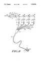
- FIG. 8shows a schematic diagram of a wire-guided, four-fiber catheter for use with the present invention.
- the laser systemis set up as previously described with the infrared laser 21 constructed in accordance with the above disclosure.
- a visible helium-neon aiming laser 20may also be used in line with laser 21 for aiming purposes as discussed with the single fiber catheter.
- the output of the infrared laser 21is directed towards a set of four mirrors 160-168 arranged at a 45° angle with respect to the axis of beam 14.
- the first mirror, 160has a 25% reflective surface and directs approximately 1/4 of the energy to focusing lens 70.
- the second mirror of the set, 162is a 33% reflector which directs 1/4 of the total energy to focusing lens 72.
- Mirror 164is a 50% reflector which directs 1/4 of the total laser output to focusing lens 74.
- the last mirror in the set, mirror 168is a 100% reflector which directs the remain 1/4 of the total energy to focusing lens 78.
- Mirrors 160-168 and lenses 70-78are conventional devices.
- Focusing lenses 70-78focus the output energy from IR laser 21 onto four fiber optic connectors 80-88.
- Connectors 80-88are connected, respectively, to tubes 90-96 which are all connected, via a branch connector 102, to catheter 104.
- Each of tubes 90-96contains a single optical fiber which transmits 1/4 of the total laser output energy through the catheter body to the catheter tip 108.
- An additional tube 98is provided which is connected to branch fitting 102 and to a conventional Luer Lok connector, 100. This latter tube is connected to a central lumen in catheter body 104 through which flushing solutions may be injected or through which a guide wire may be inserted through the catheter for purposes of guiding the catheter to the surgical area.
- Tip 108At catheter tip 108, the four optical fibers which pass through the catheter are arranged symmetrically so that the beams 110 overlap to illuminate a larger area. Tip 108 also has a hole on the center thereof, through which guidewire 112 can protrude to direct the catheter to the proper location.
- FIGS. 9 and 10show detailed views of the illustrative four-fiber catheter tip.
- the four optical fibers 42 and the inner shaft 40 which holds the fibers,are held in a fiber holder 50 which is preferably formed from a radiopaque material such as stainless steel or platinum.
- Fiber holder 50is cylindrical and is provided with a central aperture, 54, which communicates with a lumen 34 of approximately the same size that passes through the center of the catheter body 104.
- Fiber holder 50is provided with a plurality of longitudinally extending holes 56 which extend through the wall of holder 50 and receive, in a snug fit, the distal ends of the fiber cores 42.
- the distal face 158 of the combined fiber cores 42 and holder 50is polished flat to butt flush against optically transparent cap 52.
- Cap 52is cylindrical and has the same outer diameter as catheter body 104 so that the two pieces define a smooth and continuous diameter.
- Cap 52may be formed of a transparent substance such as pyrex glass or sapphire and has an enlarged bore 262 extending in from its proximal end. Bore 262 terminates at its end to form internal shoulder 260.
- a smaller diameter central aperture, 264is formed in the distal end of cap 52 which aperture may have the same diameter as aperture 54 in fiber holder 50 and lumen 34 in catheter body 104 to provide a smooth and continuous lumen which opens at the distal tip of the catheter.
- the aperture 264 in tip 52may also be somewhat narrower than aperture 14 and lumen 34 as long as sufficient clearance is provided to accommodate a guidewire without adversely interfering with fluid flow and pressure measurements.
- Cap 52is secured by an epoxy adhesive (placed on the inner surface of bore 262 to the fiber holder also to the portion of the inner shaft 40 and fibers 42 which are disposed within the proximal end of the cap 52.
- the distal end of the catheter body 104is heat shrunk around the inner shaft 40 and fibers 42 to provide a smooth transition from cap 52 to catheter body 104.
- FIG. 11illustrates the output beam pattern developed by a four-fiber catheter, such as that described above, in which the four fibers are arranged in two diametrically-opposed pairs.
- the beam pattern from each of the four fiber endsis defined by a cone formed by the ray lines 70 in FIG. 11.
- the beam from each individual fiber 42is emitted from the distal face of the fiber 42 and enters the distal segment 72 of cap 52 through the face defining the shoulder 260.
- the beam from each fiberis divergent and, the illustrative embodiment, may have a half-angle in the range of 6°-16°, depending on the numerical aperture of the fibers which are used to construct the catheter.
- FIGS. 11A, 11B and 11Cillustrate the overall beam pattern (in cross-section) which is formed by the output of the four fibers as seen along image planes 11A, 11B and 11C in FIG. 11.
- plane 11Awhich is located at the emission face 74 of cap 52, the four beams in the illustrative embodiment are still separate.
- plane 11Bthe diverging beams have spread further and have begun to overlap.
- the beamshave overlapped and define an envelop 73 having an outer diameter which is slightly greater than the outer diameter of the catheter body 104.
- beams 70will have overlapped to merge and cover a continuous pattern.
- such a mergerwill have occurred within a distance from the distal face 74 of tip 52 which is approximately equal to the outer diameter of catheter 104 (a typical diameter is 1.5 millimeters).
- a preferred application of the previously described laser catheter system of this inventionis the removal of atherosclerotic plaque.
- the lasermust be operated in a pulsed mode to remove such plaque.
- a continuous wave laseris unsuitable for plaque removal, since a continuous wave laser transmits insufficient energy to the surgical site at a time to vaporize the tissue before the energy is dissipated by thermal diffusion. As a consequence, typically, carbon deposits are formed in the affected area, and it is difficult to cleanly and accurately remove plaque from artery walls using a continuous wave laser.
- Holmium-doped lasersoperating at a wavelength in the range of from about 1.90 to 2.10 micrometers are particularly suited for such surgical applications.
- Holmium-doped lasersoperate in the preferred range of wavelengths of 1.4-2.2 micrometers, and they can be operated in a pulsed mode.
- Holmium-doped lasersare generally very efficient, generating 10 watts of average power for every kilowatt of electrical power supplied to the lamp. Because of these power requirements, which are lower than for most conventional lasers, no open loop cooling is required.
- laserscan be operated with a conventional 110 volt power source.
- Holmium-doped laser sourcesoften are portable, and can be operated either in a hospital environment, or in a doctor's office, or even in the home.
- a laser source which is preferredis a Holmium-doped Yttrium-Scandium-Gadolinium-Garnet (YSGG) laser operating at a wavelength of 2.088 micrometers. Such a laser can remove any tissue containing water.
- YSGGHolmium-doped Yttrium-Scandium-Gadolinium-Garnet
- the pulse width of any laser which is used for plaque removalshould be substantially less than the thermal time constant for that particular tissue. Typically, the pulse width should be roughly an order of magnitude less than the thermal time constant. For wavelengths in the range of 1.4-2.2 micrometers, thermal diffusion, which is a function of absorption, is reduced to an insignificant factor when such pulse widths are used. For a given power or energy level delivered per pulse, pulses longer than the thermal time constant will be generally incapable of precisely removing tissue, because the energy delivered thereby will be dissipated through thermal diffusion.
- the thermal time constantis equal to the absorption length of that particular tissue type squared over four times its thermal diffusivity.
- the thermal diffusivityis equal to about 1 ⁇ 10 -3 cm 2 /sec
- the thermal diffusivityis equal to about 1.2 ⁇ 10 -3 cm 2 /sec.
- the absorption length for most types of plaqueis about 2 ⁇ 10 -2 cm.
- the thermal time constantis approximately 8.3 ⁇ 10 -2 seconds. Therefore, typically, the pulse width should be of the order of about 8.3 milliseconds or less.
- the repetition rateis not critical, and typically is in the range of 1-10 Hertz.
- the preferred rate, for use with a Holmium-doped laser,is about 2 Hertz.
- the energy density deliveredis defined as the energy per pulse divided by the spot size.
- the spot sizeis the area of the spot upon which the laser energy is incident. It has been predicted theoretically and verified experimentally that for plaque removal, the energy density of each pulse should exceed some threshold value. If the energy density is less than this threshold value, the energy will be dissipated by thermal diffusion before the tissue is vaporized, and no vaporization will occur. It has been found that most energy densities above the threshold value can be used, up to the operational limit of the laser and the associated fiber optic system.
- the threshold value of the energy density for plaquewill vary, depending upon the particular tissue sample involved. Generally, tissue samples with more calcification or less water content will vaporize at a higher threshold value, while tissue samples with less calcification, or a higher water content, will vaporize at a lower threshold value.
- a thermal modelwas developed for laser pulses whose pulse widths are small compared to the thermal time constant of the material with which the laser is to be used. Using this thermal model, one can develop predicted threshold energy densities per pulse for lasers operating at different wavelengths, as well as the extent of thermal damage or the extent of the denatured rim.
- the energy profile in the tissuecan be described as a function with separable axial and radial components.
- the axial componentcan be described by the attentuation coefficient according to Beer's law and the radial component can be described by a linearly expanding Gaussian distribution.
- the axial and radial componentscan be defined mathematically as follows:
- J(r,z)is the spatial energy distribution
- zis the axial distance into the tissue measured from the tissue-air or tissue-water interface
- ⁇is the combined absorption-scattering attenuation coefficient
- ris the radial distance measured from the optical axis
- xis the 1/e 2 beam width of the Gaussian-like radial light distribution.
- the amount of energy, ⁇ J, deposited into a volume elementis equal to the energy profile divided by the volume as a function of the radial distance measured from the optical axis or ##EQU1##
- Beam spreadingoccurs due to multiple scattering. Measurements have shown that the beam spreading is linear in almost all cases, although the slope varies with different tissue samples. Because absorption dominates over scattering in mid-infrared wavelengths, spreading in this range should be quite small. Therefore, it is assumed that the radius expands with the same divergence as the incident beam.
- the threshold energy densityis the sum of the energy required to raise the tissue temperature to 150° C. from the ambient temperature of about 37° C. plus the energy required to overcome the heat of vaporization (2260 J/g).
- pis the tissue density (1.2 g/cm 3 )
- cis the specific heat (3.6 J/g° C.)
- L vis the heat of vaporization (2260 J/g). It can be seen that the total energy density required to vaporize a volume element is 3200 J/cm 3 . When the deposited energy density is between 488 and 3200 J/cm 3 , the tissue temperature remains at 150° C.
- the vaporization thresholdis defined as being reached if enough energy is supplied to vaporize tissue out to the edge of a 1 millimeter hole. This definition means that both the central peak and the wings of the Gaussian energy distribution are sufficient to vaporize tissue.
- the thermal zone of damageis defined as the region in which the temperature has reached above 60° C., and can vary in the axial and radial directions. Energy densities in terms of joules/mm 2 for different wavelengths can be determined based on the assumption that the depth of the hole is equal to the absorption length of the radiation at that wavelength.
- Table Isets forth the predicted threshold energy densities in joules per mm 2 and the predicted sizes of the zones of axial and radial thermal damage in micrometers for the lasers previously indicated to operate within the preferred range of wavelengths. All of these predicted energy densities are for atherosclerotic plaque having a high water content and little or no calcification.
- Apparatus 120includes a laser source 122, focusing lens and fiber optic connector 124, fiber optic 126, and a tank 128 containing the tissue sample 130.
- Laser source 122 and connector and associated lens 124are both conventional, as previously described with respect to FIGS. 3-11.
- Fiber optic 126may contain a single optical fiber, or it may contain a bundle of optical fibers. Typically, in conducting these experiments, a single fiber was used.
- Tank 128contains a saline solution in which the tissue sample 130 is immersed.
- Each optical fiber included within fiber optic 126typically is a 100 micron fiber.
- a sapphire plate 132Also immersed in the saline solution in tank 128 and covering tissue sample 130 is a sapphire plate 132.
- the end of fiber optic 126is placed in direct contact with the upper surface of plate 132, while the low surface of plate 132 is in direct contact with tissue sample.
- typically the sapphire plate 132had a thicken 1.52 millimeters.
- the sapphire plate 132is used to permit a controlled spreading of the beam of emitted from the end of fiber optic 126 to desired spot size on the tissue sample.
- Tissue sample 130 us each of these experimentscomprises a of a fatty fibrous plaque 134 disposed on a section of an aorta wall 136. Two different samples were used. Experiments 1-9 were per on Sample No. 2 while experiments 10-13 were as Sample No. 1. Sample No. 1 exhibited calcification and lower water content than Sample No. 2. Sample No. 2 exhibited virtually no calcification and a high water content. Prior to use, the tissue samples had been removed from the body, and had been carefully frozen and stored at a temperature of -70° C. The tissue samples were later thawed for use in these experiments over a lengthy period of time to avoid damage to the tissue and to avoid destruction of the cells during the freezing and thawing processes.
- a Holmium-doped YSGG laserwas operated in a pulsed mode at a wavelength of 2.088 micrometers.
- the pulse width usedwas 400 microseconds, and two pulses were emitted for each test with a spacing of one half second, or at a rate of 2 Hertz.
- the spot sizes and energies per pulsewere varied to determine the threshold energy density. The results of these experiments are set forth below in Table II.
- the value for the energy per pulse in Table IIwas measured in a conventional manner.
- the delivery area in square millimeterswas calculated from the known, controlled spreading of the light beam as it passed from fiber optic 126 through sapphire plate 132.
- the fluence, in joules per square millimeterwas calculated by dividing the energy per pulse by the delivery area.
- the ablation areais the area of the hole formed in the tissue sample.
- the extent of thermal damageis the distance beyond the rim of the hole where thermal damage was observed, while the 0D is the outside diameter of the hole formed.
- the ablation area, 0D and extent of thermal damagewere all measured microscopically from histological slides prepared from the specimens using conventional histological techniques.
- the threshold energy density per pulseis at least about 0.6 J/mm 2 for a Holmium-doped YSGG laser operating at a wavelength of 2.088 micrometers. It is expected that similar experiments using a Ho:YAG laser and a Ho:YLF laser would show that the energy threshold for such lasers is also at least about 0.6 J/mm 2 per pulse at their respective wavelengths of operation, based upon the fact that identical threshold energy densities are predicted by the theoretical model, as shown in Table I.
- the theoretically predicted threshold energy densities per pulse for vaporization of fatty fibrous plaque having virtually no calcification and a high water contentare as follows as found in Table I: Erbium YAG, 9.5 mJ/mm 2 ; Erbium YLF, 5.7 J/mm 2 ; and Thulmium YAG, 0.76 J/mm 2 .
- the precise threshold energy densitydepends upon the wavelength, and the degree of calcification and water content of the tissue sample. As indicated, the greater the calcification and the less the water content, the higher the threshold energy density required for vaporization of the tissue.
- Tables I and IIalso illustrate additional advantages of using a Holmium-doped laser within the wavelength ranges of 1.90 micrometers to 2.1 micrometers. It can be seen that the zone of thermal damage is minimal, far less than one would expect from the prior art. Furthermore, virtually no carbonization was observed in each of the experiments. Such superior results were not achieved in tests with any other existing laser source which could be delivered via a non-toxic, durable, flexible fiber optic to a vein or artery within the body.
Landscapes
- Physics & Mathematics (AREA)
- Health & Medical Sciences (AREA)
- Surgery (AREA)
- Optics & Photonics (AREA)
- Life Sciences & Earth Sciences (AREA)
- Engineering & Computer Science (AREA)
- Molecular Biology (AREA)
- Nuclear Medicine, Radiotherapy & Molecular Imaging (AREA)
- Electromagnetism (AREA)
- Biomedical Technology (AREA)
- Heart & Thoracic Surgery (AREA)
- Medical Informatics (AREA)
- Otolaryngology (AREA)
- Animal Behavior & Ethology (AREA)
- General Health & Medical Sciences (AREA)
- Public Health (AREA)
- Veterinary Medicine (AREA)
- General Physics & Mathematics (AREA)
- Laser Surgery Devices (AREA)
Abstract
Description
J(r,z)=J(r)·J(z)
TABLE I ______________________________________ Wave- Absorption Threshold Thermal Length Coeff Energy Den- Damage (μm) Laser (μm) (cm.sup.-1) sity (J/mm.sup.2) Axial Radial ______________________________________ Ho:YAG 2.1 50 .76 500 500 Ho:YSGG 2.088 50 .76 500 500 Er:YAG 1.55 2700 .0095 12 12 Ho:YLF 2.06 50 .76 100 300 Tm:YAG 1.88 50 .76 100 300 Fr:YLF 1.73 15 5.7 500 300 ______________________________________
TABLE II __________________________________________________________________________Exper- Energy/ Delivery Fluence, Ablation Thermal, iment Pulse, (Joules) Area, (mm.sup.2) Joules/mm.sup.2) Area, (mm.sup.2) OD, (mm) Damage (mm) __________________________________________________________________________1 122 × 10.sup.-3 4.012 × 10.sup.-1 0.304 N/A N/A N/A 2 222.5 × 10.sup.-3 4.012 × 10.sup.-1 0.555 N/A N/A N/A 3 310 × 10.sup.-3 4.012 × 10.sup.-1 0.773 3.848 × 10.sup.-1 100 × 10.sup.-6 50 × 10.sup.-6 4 816.2 × 10.sup.-3 3.14 × 10.sup.-2 25.98 6.158 × 10.sup.-2 280 × 10.sup.-6 240 × 10.sup.-6 5 475 × 10.sup.-3 3.14 × 10.sup.-2 15.13 4.337 × 10.sup.-2 235 × 10.sup.-6 240 × 10.sup.-6 6 268.7 × 10.sup.-3 3.14 × 10.sup.-2 8.55 5.41 × 10.sup.-3 262.5 × 10.sup.-6 100 × 10.sup.-6 7 875 × 10.sup.-3 5.3 × 10.sup.-1 1.65 5.03 × 10.sup.-1 800 × 10.sup.-6 35 × 10.sup.-6 8 760 × 10.sup.-3 5.3 × 10.sup.-1 1.434 6.36 × 10.sup.-1 900 × 10.sup.-6 35 × 10.sup.-6 9 655 × 10.sup.-3 3.14 × 10.sup.-2 20.85 1.018 × 10.sup.-1 360 × 10.sup.-6 200 × 10.sup.-6 10 185 × 10.sup.-3 3.14 × 10.sup.-2 5.89 6.157 × 10.sup.-2 280 × 10.sup.-6 35 × 10.sup.-6 11 139 × 10.sup.-3 3.14 × 10.sup.-2 4.43 4.869 × 10.sup.-2 249 × 10.sup.-6 10 × 10.sup.-6 12 271 × 10.sup.-3 3.14 × 10.sup.-2 8.63 4.869 × 10.sup.-2 249 × 10.sup.-6 25 × 10.sup.-6 13 74.5 × 10.sup.-3 3.14 × 10.sup.-2 2.37 N/A N/A N/A __________________________________________________________________________
Claims (35)
Priority Applications (1)
| Application Number | Priority Date | Filing Date | Title |
|---|---|---|---|
| US07/427,251US5196004A (en) | 1985-07-31 | 1989-10-25 | Infrared laser catheter system |
Applications Claiming Priority (4)
| Application Number | Priority Date | Filing Date | Title |
|---|---|---|---|
| US76118885A | 1985-07-31 | 1985-07-31 | |
| US1499087A | 1987-02-17 | 1987-02-17 | |
| US07/166,315US4917084A (en) | 1985-07-31 | 1988-03-10 | Infrared laser catheter system |
| US07/427,251US5196004A (en) | 1985-07-31 | 1989-10-25 | Infrared laser catheter system |
Related Parent Applications (1)
| Application Number | Title | Priority Date | Filing Date |
|---|---|---|---|
| US07/166,315Continuation-In-PartUS4917084A (en) | 1985-07-31 | 1988-03-10 | Infrared laser catheter system |
Publications (1)
| Publication Number | Publication Date |
|---|---|
| US5196004Atrue US5196004A (en) | 1993-03-23 |
Family
ID=27486440
Family Applications (1)
| Application Number | Title | Priority Date | Filing Date |
|---|---|---|---|
| US07/427,251Expired - LifetimeUS5196004A (en) | 1985-07-31 | 1989-10-25 | Infrared laser catheter system |
Country Status (1)
| Country | Link |
|---|---|
| US (1) | US5196004A (en) |
Cited By (110)
| Publication number | Priority date | Publication date | Assignee | Title |
|---|---|---|---|---|
| US5383467A (en)* | 1992-11-18 | 1995-01-24 | Spectrascience, Inc. | Guidewire catheter and apparatus for diagnostic imaging |
| US5400428A (en)* | 1992-05-13 | 1995-03-21 | Spectranetics Corporation | Method and apparatus for linearly scanning energy over an optical fiber array and coupler for coupling energy to the optical fiber array |
| US5439000A (en)* | 1992-11-18 | 1995-08-08 | Spectrascience, Inc. | Method of diagnosing tissue with guidewire |
| US5496306A (en)* | 1990-09-21 | 1996-03-05 | Light Age, Inc. | Pulse stretched solid-state laser lithotripter |
| WO1998030283A1 (en)* | 1997-01-10 | 1998-07-16 | Laser Biotherapy, Inc. | Biological tissue stimulation by optical energy |
| US5807383A (en)* | 1996-05-13 | 1998-09-15 | United States Surgical Corporation | Lasing device |
| US5820626A (en)* | 1996-07-30 | 1998-10-13 | Laser Aesthetics, Inc. | Cooling laser handpiece with refillable coolant reservoir |
| US5835647A (en)* | 1994-08-18 | 1998-11-10 | Aesculap Ag & Co. Kg | Device for generating a laser beam having a homogenized cross section and use of this beam |
| US5843073A (en)* | 1985-07-31 | 1998-12-01 | Rare Earth Medical, Inc. | Infrared laser catheter system |
| US5876426A (en)* | 1996-06-13 | 1999-03-02 | Scimed Life Systems, Inc. | System and method of providing a blood-free interface for intravascular light delivery |
| US5940420A (en)* | 1996-10-08 | 1999-08-17 | Trimedyne, Inc. | Split-flow laser cooling cavity |
| US5947989A (en)* | 1996-12-12 | 1999-09-07 | United States Surgical Corporation | Method and apparatus for transmyocardial revascularization |
| WO2000001444A1 (en)* | 1998-07-06 | 2000-01-13 | Brown, Mary, R. | Method and device for stimulating the immune system and generating healing at the cellular level |
| US6134003A (en)* | 1991-04-29 | 2000-10-17 | Massachusetts Institute Of Technology | Method and apparatus for performing optical measurements using a fiber optic imaging guidewire, catheter or endoscope |
| US6135996A (en)* | 1998-04-17 | 2000-10-24 | Baxter International, Inc. | Controlled advancement lasing device |
| US6267779B1 (en) | 1999-03-29 | 2001-07-31 | Medelaser, Llc | Method and apparatus for therapeutic laser treatment |
| US6283955B1 (en) | 1996-05-13 | 2001-09-04 | Edwards Lifesciences Corp. | Laser ablation device |
| US6287300B1 (en)* | 1996-12-09 | 2001-09-11 | Tokyo Iken Co., Ltd. | Optical fiber unit for medical examination and treatment and arm device for the optical fiber |
| WO2002015808A1 (en)* | 2000-08-23 | 2002-02-28 | Meister Joerg | Medical laser treatment module |
| US20020091377A1 (en)* | 2000-01-25 | 2002-07-11 | Anderson R. Rox | Method and apparatus for medical treatment utilizing long duration electromagnetic radiation |
| US6421164B2 (en) | 1991-04-29 | 2002-07-16 | Massachusetts Institute Of Technology | Interferometeric imaging with a grating based phase control optical delay line |
| US6440125B1 (en)* | 2000-01-04 | 2002-08-27 | Peter Rentrop | Excimer laser catheter |
| US6445939B1 (en) | 1999-08-09 | 2002-09-03 | Lightlab Imaging, Llc | Ultra-small optical probes, imaging optics, and methods for using same |
| US20020139586A1 (en)* | 2000-07-28 | 2002-10-03 | Webb Charles T. | Drill device for a drilling apparatus |
| US20020161357A1 (en)* | 2000-12-28 | 2002-10-31 | Anderson R. Rox | Method and apparatus for EMR treatment |
| US6485413B1 (en) | 1991-04-29 | 2002-11-26 | The General Hospital Corporation | Methods and apparatus for forward-directed optical scanning instruments |
| US6501551B1 (en) | 1991-04-29 | 2002-12-31 | Massachusetts Institute Of Technology | Fiber optic imaging endoscope interferometer with at least one faraday rotator |
| US6508813B1 (en) | 1996-12-02 | 2003-01-21 | Palomar Medical Technologies, Inc. | System for electromagnetic radiation dermatology and head for use therewith |
| US6511475B1 (en) | 1997-05-15 | 2003-01-28 | The General Hospital Corporation | Heads for dermatology treatment |
| US6514278B1 (en)* | 1998-05-28 | 2003-02-04 | Carl Baasel Lasertechnik Gmbh | Method and device for the superficial heating of tissue |
| US6517532B1 (en) | 1997-05-15 | 2003-02-11 | Palomar Medical Technologies, Inc. | Light energy delivery head |
| US6567431B2 (en)* | 1999-05-26 | 2003-05-20 | University Of Central Florida | Multi-wavelengths infrared laser |
| US20030144713A1 (en)* | 1996-04-09 | 2003-07-31 | Cynosure, Inc. | Ultra-long flashlamp-excited pulse dye laser for therapy and method therefor |
| US6605080B1 (en)* | 1998-03-27 | 2003-08-12 | The General Hospital Corporation | Method and apparatus for the selective targeting of lipid-rich tissues |
| US6653618B2 (en) | 2000-04-28 | 2003-11-25 | Palomar Medical Technologies, Inc. | Contact detecting method and apparatus for an optical radiation handpiece |
| US6669685B1 (en)* | 1997-11-06 | 2003-12-30 | Biolase Technology, Inc. | Tissue remover and method |
| US20040010298A1 (en)* | 2001-12-27 | 2004-01-15 | Gregory Altshuler | Method and apparatus for improved vascular related treatment |
| US20040015156A1 (en)* | 1998-12-03 | 2004-01-22 | Vasily David B. | Method and apparatus for laser removal of hair |
| US20040034319A1 (en)* | 2002-03-12 | 2004-02-19 | Palomar Medical Technologies, Inc. | Method and apparatus for hair growth management |
| US20040073079A1 (en)* | 2002-06-19 | 2004-04-15 | Palomar Medical Technologies, Inc. | Method and apparatus for treatment of cutaneous and subcutaneous conditions |
| US6723090B2 (en) | 2001-07-02 | 2004-04-20 | Palomar Medical Technologies, Inc. | Fiber laser device for medical/cosmetic procedures |
| US20040092913A1 (en)* | 2002-10-31 | 2004-05-13 | Hennings David R. | Endovenous closure of varicose veins with mid infrared laser |
| US20040093042A1 (en)* | 2002-06-19 | 2004-05-13 | Palomar Medical Technologies, Inc. | Method and apparatus for photothermal treatment of tissue at depth |
| US20040126272A1 (en)* | 2002-08-28 | 2004-07-01 | Eric Bornstein | Near infrared microbial elimination laser system |
| US20040147984A1 (en)* | 2001-11-29 | 2004-07-29 | Palomar Medical Technologies, Inc. | Methods and apparatus for delivering low power optical treatments |
| US20040156743A1 (en)* | 2002-08-28 | 2004-08-12 | Eric Bornstein | Near infrared microbial elimination laser system |
| US20040162596A1 (en)* | 2002-10-07 | 2004-08-19 | Palomar Medical Technologies, Inc. | Methods and apparatus for performing photobiostimulation |
| US20040202982A1 (en)* | 2002-12-02 | 2004-10-14 | Bornstein Eric S. | Laser augmented periodontal scaling instruments |
| US20040224288A1 (en)* | 2003-05-08 | 2004-11-11 | Eric Bornstein | Instrument for delivery of optical energy to the dental root canal system for hidden bacterial and live biofilm thermolysis |
| US20040225339A1 (en)* | 2002-12-20 | 2004-11-11 | Palomar Medical Technologies Inc. | Light treatments for acne and other disorders of follicles |
| US6819951B2 (en) | 2002-09-24 | 2004-11-16 | Mayo Foundation For Medical Education And Research | Peripherally inserted central catheter with continuous central venous oximetry and proximal high flow port |
| US20050154382A1 (en)* | 2003-12-31 | 2005-07-14 | Altshuler Gregory B. | Dermatological treatment with visualization |
| US20050168158A1 (en)* | 2001-03-01 | 2005-08-04 | Palomar Medical Technologies, Inc. | Flash lamp drive circuit |
| US20050256516A1 (en)* | 2004-01-08 | 2005-11-17 | Dmitri Boutoussov | Illumination device and related methods |
| US20060004306A1 (en)* | 2004-04-09 | 2006-01-05 | Palomar Medical Technologies, Inc. | Methods and products for producing lattices of EMR-treated islets in tissues, and uses therefor |
| US20060009794A1 (en)* | 2002-09-09 | 2006-01-12 | Acp Japan Co., Ltd. | Stripping wire and stripping catheter for evulsing vein |
| US20060009750A1 (en)* | 2001-03-02 | 2006-01-12 | Palomar Medical Technologies, Inc. | Apparatus and method for treatment using a patterned mask |
| US20060036164A1 (en)* | 2001-06-19 | 2006-02-16 | The Trustees Of The University Of Pennsylvania | Optically guided system for precise placement of a medical catheter in a patient |
| US20060099548A1 (en)* | 2004-08-13 | 2006-05-11 | Rizoiu Ioana M | Caries detection using timing differentials between excitation and return pulses |
| US20060206103A1 (en)* | 2001-03-02 | 2006-09-14 | Palomar Medical Technologies, Inc. | Dermatological treatment device |
| US20060253176A1 (en)* | 2005-02-18 | 2006-11-09 | Palomar Medical Technologies, Inc. | Dermatological treatment device with deflector optic |
| US7135033B2 (en) | 2002-05-23 | 2006-11-14 | Palomar Medical Technologies, Inc. | Phototreatment device for use with coolants and topical substances |
| US20060293644A1 (en)* | 2005-06-21 | 2006-12-28 | Donald Umstadter | System and methods for laser-generated ionizing radiation |
| US20070016176A1 (en)* | 2004-08-13 | 2007-01-18 | Dmitri Boutoussov | Laser handpiece architecture and methods |
| US20070014322A1 (en)* | 1995-08-31 | 2007-01-18 | Biolase Technology, Inc. | Electromagnetic energy distributions for electromagnetically induced mechanical cutting |
| US7169140B1 (en) | 1994-02-22 | 2007-01-30 | Boston Scientific Scimed, Inc. | Methods of using an intravascular balloon catheter in combination with an angioscope |
| US20070038206A1 (en)* | 2004-12-09 | 2007-02-15 | Palomar Medical Technologies, Inc. | Photocosmetic device |
| US7204832B2 (en) | 1996-12-02 | 2007-04-17 | Pálomar Medical Technologies, Inc. | Cooling system for a photo cosmetic device |
| US20070123846A1 (en)* | 2002-10-31 | 2007-05-31 | Cooltouch Incorporated | Preparation for endovenous laser ablation |
| US20070129711A1 (en)* | 1999-01-08 | 2007-06-07 | Altshuler Gregory B | Cooling system for a photocosmetic device |
| US20070194717A1 (en)* | 2006-02-17 | 2007-08-23 | Palomar Medical Technologies, Inc. | Lamp for use in a tissue treatment device |
| US20070197884A1 (en)* | 2006-01-24 | 2007-08-23 | Nomir Medical Technologies, Inc. | Optical method and device for modulation of biochemical processes in adipose tissue |
| US20070219605A1 (en)* | 2006-03-20 | 2007-09-20 | Palomar Medical Technologies, Inc. | Treatment of tissue volume with radiant energy |
| US7273056B2 (en) | 2001-06-19 | 2007-09-25 | The Trustees Of The University Of Pennsylvania | Optical guidance system for invasive catheter placement |
| US20070255355A1 (en)* | 2006-04-06 | 2007-11-01 | Palomar Medical Technologies, Inc. | Apparatus and method for skin treatment with compression and decompression |
| US7320594B1 (en) | 1995-08-31 | 2008-01-22 | Biolase Technology, Inc. | Fluid and laser system |
| US20080021527A1 (en)* | 2003-10-30 | 2008-01-24 | Cooltouch Incorporated | Endovenous laser treatment generating reduced blood coagulation |
| US20080039715A1 (en)* | 2004-11-04 | 2008-02-14 | Wilson David F | Three-dimensional optical guidance for catheter placement |
| US20080091179A1 (en)* | 1999-12-10 | 2008-04-17 | Candela Corporation | Compact, handheld device for home-based acne treatment |
| US20080131968A1 (en)* | 2002-08-28 | 2008-06-05 | Nomir Medical Technologies, Inc. | Near-infrared electromagnetic modification of cellular steady-state membrane potentials |
| US20080157690A1 (en)* | 2001-05-02 | 2008-07-03 | Biolase Technology, Inc. | Electromagnetic energy distributions for electromagnetically induced mechanical cutting |
| US20080183162A1 (en)* | 2000-12-28 | 2008-07-31 | Palomar Medical Technologies, Inc. | Methods And Devices For Fractional Ablation Of Tissue |
| US20080186591A1 (en)* | 2007-02-01 | 2008-08-07 | Palomar Medical Technologies, Inc. | Dermatological device having a zoom lens system |
| US20080194973A1 (en)* | 2005-09-13 | 2008-08-14 | Imam Farhad B | Light-guided transluminal catheter |
| US20080294153A1 (en)* | 1996-12-02 | 2008-11-27 | Palomar Medical Technologies, Inc. | Cooling System For A Photocosmetic Device |
| US20090118721A1 (en)* | 2005-07-21 | 2009-05-07 | Eric Bornstein | Near Infrared Microbial Elimination Laser System (NIMELS) |
| US20090187169A1 (en)* | 1999-12-10 | 2009-07-23 | Candela Corporation | Method of Treating Disorders Associated with Sebaceous Follicles |
| US20090298004A1 (en)* | 1997-11-06 | 2009-12-03 | Rizoiu Ioana M | Tunnelling probe |
| US7713294B2 (en) | 2002-08-28 | 2010-05-11 | Nomir Medical Technologies, Inc. | Near infrared microbial elimination laser systems (NIMEL) |
| US20100125291A1 (en)* | 1995-08-31 | 2010-05-20 | Rizoiu Ioana M | Drill and flavored fluid particles combination |
| US20100185188A1 (en)* | 1997-06-12 | 2010-07-22 | Dmitri Boutoussov | Electromagnetically induced treatment devices and methods |
| EP2241280A3 (en)* | 2009-04-07 | 2010-11-17 | Lumenis Ltd. | Tissue treatment apparatus and methods |
| US20110046616A1 (en)* | 2009-04-01 | 2011-02-24 | The General Hospital Corporation | Apparatus and method for fat removal |
| US8078261B2 (en) | 2005-09-13 | 2011-12-13 | Children's Medical Center Corporation | Light-guided transluminal catheter |
| WO2012114334A1 (en)* | 2011-02-24 | 2012-08-30 | Ilan Ben Oren | Hybrid catheter for endoluminal intervention |
| US8268332B2 (en) | 2004-04-01 | 2012-09-18 | The General Hospital Corporation | Method for dermatological treatment using chromophores |
| US20120301045A1 (en)* | 2010-02-17 | 2012-11-29 | Canon Kabushiki Kaisha | Image processing method for mass spectrum image, program, and apparatus |
| US8346347B2 (en) | 2005-09-15 | 2013-01-01 | Palomar Medical Technologies, Inc. | Skin optical characterization device |
| US8409183B2 (en) | 2003-10-30 | 2013-04-02 | Cooltouch Incorporated | Endovenous laser treatment generating reduced blood coagulation |
| US8506979B2 (en) | 2002-08-28 | 2013-08-13 | Nomir Medical Technologies, Inc. | Near-infrared electromagnetic modification of cellular steady-state membrane potentials |
| US9028536B2 (en) | 2006-08-02 | 2015-05-12 | Cynosure, Inc. | Picosecond laser apparatus and methods for its operation and use |
| US9780518B2 (en) | 2012-04-18 | 2017-10-03 | Cynosure, Inc. | Picosecond laser apparatus and methods for treating target tissues with same |
| US9919168B2 (en) | 2009-07-23 | 2018-03-20 | Palomar Medical Technologies, Inc. | Method for improvement of cellulite appearance |
| US10245107B2 (en) | 2013-03-15 | 2019-04-02 | Cynosure, Inc. | Picosecond optical radiation systems and methods of use |
| US10434324B2 (en) | 2005-04-22 | 2019-10-08 | Cynosure, Llc | Methods and systems for laser treatment using non-uniform output beam |
| US11007373B1 (en) | 2002-12-20 | 2021-05-18 | James Andrew Ohneck | Photobiostimulation device and method of using same |
| US11418000B2 (en) | 2018-02-26 | 2022-08-16 | Cynosure, Llc | Q-switched cavity dumped sub-nanosecond laser |
| US11684420B2 (en) | 2016-05-05 | 2023-06-27 | Eximo Medical Ltd. | Apparatus and methods for resecting and/or ablating an undesired tissue |
| US12038322B2 (en) | 2022-06-21 | 2024-07-16 | Eximo Medical Ltd. | Devices and methods for testing ablation systems |
| US12376904B1 (en) | 2020-09-08 | 2025-08-05 | Angiodynamics, Inc. | Dynamic laser stabilization and calibration system |
Citations (61)
| Publication number | Priority date | Publication date | Assignee | Title |
|---|---|---|---|---|
| US1751584A (en)* | 1927-08-13 | 1930-03-25 | Rca Corp | Picture transmission |
| US3327712A (en)* | 1961-09-15 | 1967-06-27 | Ira H Kaufman | Photocoagulation type fiber optical surgical device |
| US3769963A (en)* | 1972-03-31 | 1973-11-06 | L Goldman | Instrument for performing laser micro-surgery and diagnostic transillumination of living human tissue |
| US3884236A (en)* | 1971-10-28 | 1975-05-20 | Mikhail M Krasnov | Method of glaucoma treatment |
| US3947780A (en)* | 1974-10-21 | 1976-03-30 | Mcdonnell Douglas Corporation | Acoustooptic mode-locker frequency doubler |
| US3983511A (en)* | 1975-09-08 | 1976-09-28 | Sanders Associates, Inc. | Normal incidence face pumped disc laser |
| US4110702A (en)* | 1976-11-24 | 1978-08-29 | Sanders Associates, Inc. | Deep red laser |
| US4141362A (en)* | 1977-05-23 | 1979-02-27 | Richard Wolf Gmbh | Laser endoscope |
| US4146019A (en)* | 1976-09-30 | 1979-03-27 | University Of Southern California | Multichannel endoscope |
| US4170997A (en)* | 1977-08-26 | 1979-10-16 | Hughes Aircraft Company | Medical laser instrument for transmitting infrared laser energy to a selected part of the body |
| US4207874A (en)* | 1978-03-27 | 1980-06-17 | Choy Daniel S J | Laser tunnelling device |
| US4233493A (en)* | 1974-05-21 | 1980-11-11 | Nath Guenther | Apparatus for applying intense light radiation to a limited area |
| US4266548A (en)* | 1978-12-18 | 1981-05-12 | Davi S K | Apparatus for and method of utilizing energy to excise pathological tissue |
| US4309998A (en)* | 1978-06-08 | 1982-01-12 | Aron Rosa Daniele S | Process and apparatus for ophthalmic surgery |
| US4321559A (en)* | 1980-04-03 | 1982-03-23 | The United States Of America As Represented By The Secretary Of The Navy | Multiwavelength self-pumped solid state laser |
| US4330763A (en)* | 1980-03-19 | 1982-05-18 | The United States Of America As Represented By The Secretary Of The Navy | Resonantly pumped mid-ir laser |
| US4350150A (en)* | 1979-09-25 | 1982-09-21 | Olympus Optical Co., Ltd. | Structure of a light-receiving end portion of an endoscope light guide |
| US4353893A (en)* | 1980-05-22 | 1982-10-12 | Kowa Company, Ltd. | Ka-6606 Aminoglycosides antibiotics and compositions thereof |
| WO1983001311A1 (en)* | 1981-10-08 | 1983-04-14 | Chapman, John, Gerald | Improvements relating to light delivery for tumour treatment |
| US4383729A (en)* | 1979-11-12 | 1983-05-17 | Fuji Photo Optical Co., Ltd. | Light transmitting system comprising beam dividing and compositing means |
| US4386428A (en)* | 1980-10-14 | 1983-05-31 | Sanders Associates, Inc. | Tripled Nd:YAG Pumped Tm3+ laser oscillator |
| US4418688A (en)* | 1981-07-06 | 1983-12-06 | Laserscope, Inc. | Microcatheter having directable laser and expandable walls |
| US4425503A (en)* | 1980-08-05 | 1984-01-10 | The United States Of America As Represented By The Secretary Of The Army | Method for detecting the presence of a gas in an atmosphere |
| US4445418A (en)* | 1980-12-11 | 1984-05-01 | Chartered Industries Of Singapore Private Limited | Drum magazine for a gun |
| US4454882A (en)* | 1981-07-29 | 1984-06-19 | Olympus Optical Co., Ltd. | Laser apparatus utilizing marking laser for triggering operative laser |
| US4458683A (en)* | 1981-05-26 | 1984-07-10 | Agency Of Industrial Science & Technology | Focal point direct observation type laser scalpel device |
| US4469098A (en)* | 1978-12-18 | 1984-09-04 | Davi Samantha K | Apparatus for and method of utilizing energy to excise pathological tissue |
| US4470407A (en)* | 1982-03-11 | 1984-09-11 | Laserscope, Inc. | Endoscopic device |
| US4503854A (en)* | 1983-06-16 | 1985-03-12 | Jako Geza J | Laser surgery |
| US4504297A (en)* | 1983-07-06 | 1985-03-12 | At&T Bell Laboratories | Optical fiber preform manufacturing method |
| US4515612A (en)* | 1982-04-19 | 1985-05-07 | At&T Bell Laboratories | Method for optical fiber fabrication including deuterium/hydrogen exchange |
| US4538608A (en)* | 1984-03-23 | 1985-09-03 | Esperance Jr Francis A L | Method and apparatus for removing cataractous lens tissue by laser radiation |
| US4556057A (en)* | 1982-08-31 | 1985-12-03 | Hamamatsu Tv Co., Ltd. | Cancer diagnosis device utilizing laser beam pulses |
| US4559942A (en)* | 1984-02-29 | 1985-12-24 | William Eisenberg | Method utilizing a laser for eye surgery |
| US4566453A (en)* | 1982-12-23 | 1986-01-28 | Tohoku Ricoh Co., Ltd. | Vascular anastomosis apparatus |
| US4566765A (en)* | 1982-10-15 | 1986-01-28 | Hitachi, Ltd. | Apparatus for summing several ring-shape laser beams |
| US4572189A (en)* | 1983-10-11 | 1986-02-25 | Smith Chadwick F | Electronic controller for use with a surgical laser system |
| US4576177A (en)* | 1983-02-18 | 1986-03-18 | Webster Wilton W Jr | Catheter for removing arteriosclerotic plaque |
| US4641912A (en)* | 1984-12-07 | 1987-02-10 | Tsvi Goldenberg | Excimer laser delivery system, angioscope and angioplasty system incorporating the delivery system and angioscope |
| US4648892A (en)* | 1985-03-22 | 1987-03-10 | Massachusetts Institute Of Technology | Method for making optical shield for a laser catheter |
| US4654024A (en)* | 1985-09-04 | 1987-03-31 | C.R. Bard, Inc. | Thermorecanalization catheter and method for use |
| US4672969A (en)* | 1983-10-06 | 1987-06-16 | Sonomo Corporation | Laser healing method |
| US4685458A (en)* | 1984-03-01 | 1987-08-11 | Vaser, Inc. | Angioplasty catheter and method for use thereof |
| US4686979A (en)* | 1984-01-09 | 1987-08-18 | The United States Of America As Represented By The United States Department Of Energy | Excimer laser phototherapy for the dissolution of abnormal growth |
| US4732448A (en)* | 1984-12-07 | 1988-03-22 | Advanced Interventional Systems, Inc. | Delivery system for high-energy pulsed ultraviolet laser light |
| US4750486A (en)* | 1985-08-14 | 1988-06-14 | Butler Philip H | Apparatus for moving a mirror |
| US4775361A (en)* | 1986-04-10 | 1988-10-04 | The General Hospital Corporation | Controlled removal of human stratum corneum by pulsed laser to enhance percutaneous transport |
| US4784135A (en)* | 1982-12-09 | 1988-11-15 | International Business Machines Corporation | Far ultraviolet surgical and dental procedures |
| US4784132A (en)* | 1983-03-25 | 1988-11-15 | Fox Kenneth R | Method of and apparatus for laser treatment of body lumens |
| US4799754A (en)* | 1985-09-25 | 1989-01-24 | Advanced Interventional Systems, Inc. | Delivery system for high-energy pulsed ultraviolet laser light |
| US4800876A (en)* | 1981-12-11 | 1989-01-31 | Fox Kenneth R | Method of and apparatus for laser treatment of body lumens |
| US4817601A (en)* | 1985-03-06 | 1989-04-04 | C. R. Bard, Inc. | Catheter system for controlled removal by radiant energy of biological obstructions |
| US4819632A (en)* | 1986-05-19 | 1989-04-11 | Davies David H | Retrolasing catheter and method |
| US4830460A (en)* | 1987-05-19 | 1989-05-16 | Advanced Interventional Systems, Inc. | Guidance system and method for delivery system for high-energy pulsed ultraviolet laser light |
| US4848336A (en)* | 1981-12-11 | 1989-07-18 | Fox Kenneth R | Apparatus for laser treatment of body lumens |
| US4850351A (en)* | 1985-05-22 | 1989-07-25 | C. R. Bard, Inc. | Wire guided laser catheter |
| US4852567A (en)* | 1988-01-21 | 1989-08-01 | C. R. Bard, Inc. | Laser tipped catheter |
| US4854315A (en)* | 1987-06-25 | 1989-08-08 | Stack Richard S | Laser catheter |
| US4878492A (en)* | 1987-10-08 | 1989-11-07 | C. R. Bard, Inc. | Laser balloon catheter |
| US4917084A (en)* | 1985-07-31 | 1990-04-17 | C. R. Bard, Inc. | Infrared laser catheter system |
| US4929246A (en)* | 1988-10-27 | 1990-05-29 | C. R. Bard, Inc. | Method for closing and sealing an artery after removing a catheter |
- 1989
- 1989-10-25USUS07/427,251patent/US5196004A/ennot_activeExpired - Lifetime
Patent Citations (65)
| Publication number | Priority date | Publication date | Assignee | Title |
|---|---|---|---|---|
| US1751584A (en)* | 1927-08-13 | 1930-03-25 | Rca Corp | Picture transmission |
| US3327712A (en)* | 1961-09-15 | 1967-06-27 | Ira H Kaufman | Photocoagulation type fiber optical surgical device |
| US3884236A (en)* | 1971-10-28 | 1975-05-20 | Mikhail M Krasnov | Method of glaucoma treatment |
| US3769963A (en)* | 1972-03-31 | 1973-11-06 | L Goldman | Instrument for performing laser micro-surgery and diagnostic transillumination of living human tissue |
| US4233493A (en)* | 1974-05-21 | 1980-11-11 | Nath Guenther | Apparatus for applying intense light radiation to a limited area |
| US3947780A (en)* | 1974-10-21 | 1976-03-30 | Mcdonnell Douglas Corporation | Acoustooptic mode-locker frequency doubler |
| US3983511A (en)* | 1975-09-08 | 1976-09-28 | Sanders Associates, Inc. | Normal incidence face pumped disc laser |
| US4146019A (en)* | 1976-09-30 | 1979-03-27 | University Of Southern California | Multichannel endoscope |
| US4110702A (en)* | 1976-11-24 | 1978-08-29 | Sanders Associates, Inc. | Deep red laser |
| US4141362A (en)* | 1977-05-23 | 1979-02-27 | Richard Wolf Gmbh | Laser endoscope |
| US4170997A (en)* | 1977-08-26 | 1979-10-16 | Hughes Aircraft Company | Medical laser instrument for transmitting infrared laser energy to a selected part of the body |
| US4207874A (en)* | 1978-03-27 | 1980-06-17 | Choy Daniel S J | Laser tunnelling device |
| US4309998A (en)* | 1978-06-08 | 1982-01-12 | Aron Rosa Daniele S | Process and apparatus for ophthalmic surgery |
| US4266548A (en)* | 1978-12-18 | 1981-05-12 | Davi S K | Apparatus for and method of utilizing energy to excise pathological tissue |
| US4469098A (en)* | 1978-12-18 | 1984-09-04 | Davi Samantha K | Apparatus for and method of utilizing energy to excise pathological tissue |
| US4350150A (en)* | 1979-09-25 | 1982-09-21 | Olympus Optical Co., Ltd. | Structure of a light-receiving end portion of an endoscope light guide |
| US4383729A (en)* | 1979-11-12 | 1983-05-17 | Fuji Photo Optical Co., Ltd. | Light transmitting system comprising beam dividing and compositing means |
| US4330763A (en)* | 1980-03-19 | 1982-05-18 | The United States Of America As Represented By The Secretary Of The Navy | Resonantly pumped mid-ir laser |
| US4321559A (en)* | 1980-04-03 | 1982-03-23 | The United States Of America As Represented By The Secretary Of The Navy | Multiwavelength self-pumped solid state laser |
| US4353893A (en)* | 1980-05-22 | 1982-10-12 | Kowa Company, Ltd. | Ka-6606 Aminoglycosides antibiotics and compositions thereof |
| US4425503A (en)* | 1980-08-05 | 1984-01-10 | The United States Of America As Represented By The Secretary Of The Army | Method for detecting the presence of a gas in an atmosphere |
| US4386428A (en)* | 1980-10-14 | 1983-05-31 | Sanders Associates, Inc. | Tripled Nd:YAG Pumped Tm3+ laser oscillator |
| US4445418A (en)* | 1980-12-11 | 1984-05-01 | Chartered Industries Of Singapore Private Limited | Drum magazine for a gun |
| US4458683A (en)* | 1981-05-26 | 1984-07-10 | Agency Of Industrial Science & Technology | Focal point direct observation type laser scalpel device |
| US4418688A (en)* | 1981-07-06 | 1983-12-06 | Laserscope, Inc. | Microcatheter having directable laser and expandable walls |
| US4454882A (en)* | 1981-07-29 | 1984-06-19 | Olympus Optical Co., Ltd. | Laser apparatus utilizing marking laser for triggering operative laser |
| WO1983001311A1 (en)* | 1981-10-08 | 1983-04-14 | Chapman, John, Gerald | Improvements relating to light delivery for tumour treatment |
| US4800876B1 (en)* | 1981-12-11 | 1991-07-09 | R Fox Kenneth | |
| US4848336A (en)* | 1981-12-11 | 1989-07-18 | Fox Kenneth R | Apparatus for laser treatment of body lumens |
| US4800876A (en)* | 1981-12-11 | 1989-01-31 | Fox Kenneth R | Method of and apparatus for laser treatment of body lumens |
| US4470407A (en)* | 1982-03-11 | 1984-09-11 | Laserscope, Inc. | Endoscopic device |
| US4515612A (en)* | 1982-04-19 | 1985-05-07 | At&T Bell Laboratories | Method for optical fiber fabrication including deuterium/hydrogen exchange |
| US4556057A (en)* | 1982-08-31 | 1985-12-03 | Hamamatsu Tv Co., Ltd. | Cancer diagnosis device utilizing laser beam pulses |
| US4566765A (en)* | 1982-10-15 | 1986-01-28 | Hitachi, Ltd. | Apparatus for summing several ring-shape laser beams |
| US4784135A (en)* | 1982-12-09 | 1988-11-15 | International Business Machines Corporation | Far ultraviolet surgical and dental procedures |
| US4566453A (en)* | 1982-12-23 | 1986-01-28 | Tohoku Ricoh Co., Ltd. | Vascular anastomosis apparatus |
| US4576177A (en)* | 1983-02-18 | 1986-03-18 | Webster Wilton W Jr | Catheter for removing arteriosclerotic plaque |
| US4784132A (en)* | 1983-03-25 | 1988-11-15 | Fox Kenneth R | Method of and apparatus for laser treatment of body lumens |
| US4784132B1 (en)* | 1983-03-25 | 1990-03-13 | R Fox Kenneth | |
| US4503854A (en)* | 1983-06-16 | 1985-03-12 | Jako Geza J | Laser surgery |
| US4504297A (en)* | 1983-07-06 | 1985-03-12 | At&T Bell Laboratories | Optical fiber preform manufacturing method |
| US4672969A (en)* | 1983-10-06 | 1987-06-16 | Sonomo Corporation | Laser healing method |
| US4572189A (en)* | 1983-10-11 | 1986-02-25 | Smith Chadwick F | Electronic controller for use with a surgical laser system |
| US4686979A (en)* | 1984-01-09 | 1987-08-18 | The United States Of America As Represented By The United States Department Of Energy | Excimer laser phototherapy for the dissolution of abnormal growth |
| US4559942A (en)* | 1984-02-29 | 1985-12-24 | William Eisenberg | Method utilizing a laser for eye surgery |
| US4685458A (en)* | 1984-03-01 | 1987-08-11 | Vaser, Inc. | Angioplasty catheter and method for use thereof |
| US4538608A (en)* | 1984-03-23 | 1985-09-03 | Esperance Jr Francis A L | Method and apparatus for removing cataractous lens tissue by laser radiation |
| US4732448A (en)* | 1984-12-07 | 1988-03-22 | Advanced Interventional Systems, Inc. | Delivery system for high-energy pulsed ultraviolet laser light |
| US4641912A (en)* | 1984-12-07 | 1987-02-10 | Tsvi Goldenberg | Excimer laser delivery system, angioscope and angioplasty system incorporating the delivery system and angioscope |
| US4817601A (en)* | 1985-03-06 | 1989-04-04 | C. R. Bard, Inc. | Catheter system for controlled removal by radiant energy of biological obstructions |
| US4648892A (en)* | 1985-03-22 | 1987-03-10 | Massachusetts Institute Of Technology | Method for making optical shield for a laser catheter |
| US4850351A (en)* | 1985-05-22 | 1989-07-25 | C. R. Bard, Inc. | Wire guided laser catheter |
| US4950266A (en)* | 1985-07-31 | 1990-08-21 | C. R. Bard, Inc. | Infrared laser catheter system |
| US4917084A (en)* | 1985-07-31 | 1990-04-17 | C. R. Bard, Inc. | Infrared laser catheter system |
| US4750486A (en)* | 1985-08-14 | 1988-06-14 | Butler Philip H | Apparatus for moving a mirror |
| US4654024A (en)* | 1985-09-04 | 1987-03-31 | C.R. Bard, Inc. | Thermorecanalization catheter and method for use |
| US4799754A (en)* | 1985-09-25 | 1989-01-24 | Advanced Interventional Systems, Inc. | Delivery system for high-energy pulsed ultraviolet laser light |
| US4775361A (en)* | 1986-04-10 | 1988-10-04 | The General Hospital Corporation | Controlled removal of human stratum corneum by pulsed laser to enhance percutaneous transport |
| US4819632A (en)* | 1986-05-19 | 1989-04-11 | Davies David H | Retrolasing catheter and method |
| US4830460A (en)* | 1987-05-19 | 1989-05-16 | Advanced Interventional Systems, Inc. | Guidance system and method for delivery system for high-energy pulsed ultraviolet laser light |
| US4905689A (en)* | 1987-06-25 | 1990-03-06 | Stack Richard S | Method of using a laser catheter |
| US4854315A (en)* | 1987-06-25 | 1989-08-08 | Stack Richard S | Laser catheter |
| US4878492A (en)* | 1987-10-08 | 1989-11-07 | C. R. Bard, Inc. | Laser balloon catheter |
| US4852567A (en)* | 1988-01-21 | 1989-08-01 | C. R. Bard, Inc. | Laser tipped catheter |
| US4929246A (en)* | 1988-10-27 | 1990-05-29 | C. R. Bard, Inc. | Method for closing and sealing an artery after removing a catheter |
Non-Patent Citations (39)
| Title |
|---|
| "A new cool lens capsulating laser" by Horn et al.; Am Intra-Ocular Implant Soc. J. vol. 8; Fall 1982 pp. 337-342. |
| "Noncontact tissue ablation by holmium: YSGG laser pulses in blood" by Van Leeuwen et al.; Lasers Surg. Med vol. 11, No. 1 1991 pp. 26-34. |
| A new cool lens capsulating laser by Horn et al.; Am Intra Ocular Implant Soc. J. vol. 8; Fall 1982 pp. 337 342.* |
| Abela, George S. et al., "Effects of Carbon Dioxide, Nd-YAG, and Argon Laser Radiation on Coronary Atheromatous Plaques", The American Journal of Cardiology, vol. 50, No. 6, pp. 1199-1205, Dec. 1982. |
| Abela, George S. et al., Effects of Carbon Dioxide, Nd YAG, and Argon Laser Radiation on Coronary Atheromatous Plaques , The American Journal of Cardiology, vol. 50, No. 6, pp. 1199 1205, Dec. 1982.* |
| Anderson, R. Rox and Parrish, John A., "Microvasculature Can Be Selectively Damaged Using Dye Lasers: A Basic Theory and Experimental Evidence in Human Skin", Lasers in Surgery and Medicine, vol. 1, pp. 263-276 (1981). |
| Anderson, R. Rox and Parrish, John A., "Selective Photothermolysis: Precise Microsurgery by Selective Absorption of Pulsed Radiation", Science, vol. 220, pp. 524-527, 29 Apr. 1983. |
| Anderson, R. Rox and Parrish, John A., Microvasculature Can Be Selectively Damaged Using Dye Lasers: A Basic Theory and Experimental Evidence in Human Skin , Lasers in Surgery and Medicine, vol. 1, pp. 263 276 (1981).* |
| Anderson, R. Rox and Parrish, John A., Selective Photothermolysis: Precise Microsurgery by Selective Absorption of Pulsed Radiation , Science, vol. 220, pp. 524 527, 29 Apr. 1983.* |
| Beckman, et al., Limbectomies, Keratectomies, And Keratostomies Performed With A Rapid Published Carbon Dioxide Laser, Am, J. Ophthal vol. 71, No. 6, Jun. 1971, pp. 1277 1283.* |
| Beckman, et al., Limbectomies, Keratectomies, And Keratostomies Performed With A Rapid-Published Carbon Dioxide Laser, Am, J. Ophthal vol. 71, No. 6, Jun. 1971, pp. 1277-1283. |
| E. Sinofsky, et al., Measurement of Argon Laserbeam Spreading Through Arterial Plaque, Lasers in the Life Sciences, 1(2), 1986, pp. 143 150.* |
| E. Sinofsky, et al., Measurement of Argon Laserbeam Spreading Through Arterial Plaque, Lasers in the Life Sciences, 1(2), 1986, pp. 143-150. |
| Ed Sinofsky, Comparative Thermal Modeling of Er:YAG, Ho:YAG and CO2 Laser Pulses For Tissue Vaporization, Proceedings to SPIE The Inernational Society For Optical Engineering, vol. 712, Lasers in Medicine (1986), pp. 188 192.* |
| Ed Sinofsky, Comparative Thermal Modeling of Er:YAG, Ho:YAG and CO2 Laser Pulses For Tissue Vaporization, Proceedings to SPIE-The Inernational Society For Optical Engineering, vol. 712, Lasers in Medicine (1986), pp. 188-192. |
| Fraser, A. B. et al., "Pulsed Laser Iridotomy Apparatus", The Johns Hopkins University--Applied Physics Laboratory, Oct. 1977-Sep. 1978. |
| Fraser, A. B. et al., Pulsed Laser Iridotomy Apparatus , The Johns Hopkins University Applied Physics Laboratory, Oct. 1977 Sep. 1978.* |
| Garrett Lee et al., Current and Potential Uses of Lasers In The Treatment of Of Atherosclerotic Disease, Chest, vol. 85, No. 3, Mar., 1984 pp. 429 434.* |
| Garrett Lee et al., Current and Potential Uses of Lasers In The Treatment of Of Atherosclerotic Disease, Chest, vol. 85, No. 3, Mar., 1984 pp. 429-434. |
| Garrett Lee et al., Limitations, Risks and Complications of Laser Recanalization: A Cautious Approach Warranted, The American Journal of Cardiology, vol. 56, Jun. 1, 1985, pp. 181 185.* |
| Garrett Lee et al., Limitations, Risks and Complications of Laser Recanalization: A Cautious Approach Warranted, The American Journal of Cardiology, vol. 56, Jun. 1, 1985, pp. 181-185. |
| H. Fugii, et al., Fibre Bundle Scanner For Laser Photocoagulation Treatment, Optics & Laser Technology Feb. 82 pp. 38 40.* |
| H. Fugii, et al., Fibre Bundle Scanner For Laser Photocoagulation Treatment, Optics & Laser Technology Feb. 82 pp. 38-40. |
| H. Ward, Laser Recannalization of Atheromatous Vessels Using Fiber Optics, Lasers in Surgery and Medicine 4; 353 363 (1984).* |
| H. Ward, Laser Recannalization of Atheromatous Vessels Using Fiber Optics, Lasers in Surgery and Medicine 4; 353-363 (1984). |
| L. Deckelbaum, et al., Reduction of Laser Inducted Pathological Tissue Injury Using Post Energy Delivery, vol. 56, Oct. 1, 1985, pp. 662 667.* |
| L. Deckelbaum, et al., Reduction of Laser Inducted Pathological Tissue Injury Using Post-Energy Delivery, vol. 56, Oct. 1, 1985, pp. 662-667. |
| L. Esterowitz, et al., Angioplasty with a Laser and Fiber Optics at 2.9 um, SPIE Conference, Jan. 1986, Los Angeles, Calif.* |
| Leon Goldman, et al., The Biomedical Laser: Technology And Clinical Applications, (1981).* |
| M. Motamedi, et al., Interaction of Laser Raidation with Plaque and Vessel Wall, ICALEO 84, Technical Digest.* |
| M. Motamedi, et al., Interaction of Laser Raidation with Plaque and Vessel Wall, ICALEO'84, Technical Digest. |
| Noncontact tissue ablation by holmium: YSGG laser pulses in blood by Van Leeuwen et al.; Lasers Surg. Med vol. 11, No. 1 1991 pp. 26 34.* |
| Paul E. McGuff, et al., Studies of the Surgical Applications of Laser Light ( Light Amplification by Stimulated Emission of Radiation ), Surgical Form, vol. XIV, American College of Surgeons, Chicago, Ill. (1963).* |
| Paul E. McGuff, et al., Studies of the Surgical Applications of Laser Light (Light Amplification by Stimulated Emission of Radiation), Surgical Form, vol. XIV, American College of Surgeons, Chicago, Ill. (1963). |
| Solid State Laser Engineering; Springer Verlag New York Heidelberg Berlin 1976; Walter Koechner.* |
| Solid State Laser Engineering; Springer-Verlag New York Heidelberg Berlin 1976; Walter Koechner. |
| The happy merger of fiber optics and lasers; David N, Kay; Information Retrieval No. 22; News RT 167 Electronic Design, vol. 17 Jun. 21, 1969.* |
| Wolbarsht, Myron L., "Interactions Between Material Processing and Surgery", ICALEO, 4/L.I.A., vol. 32 (1982). |
| Wolbarsht, Myron L., Interactions Between Material Processing and Surgery , ICALEO, 4/L.I.A., vol. 32 (1982).* |
Cited By (208)
| Publication number | Priority date | Publication date | Assignee | Title |
|---|---|---|---|---|
| US6547780B1 (en) | 1985-07-31 | 2003-04-15 | Cardiofocus, Inc. | Infrared laser catheter system |
| US5843073A (en)* | 1985-07-31 | 1998-12-01 | Rare Earth Medical, Inc. | Infrared laser catheter system |
| US5496306A (en)* | 1990-09-21 | 1996-03-05 | Light Age, Inc. | Pulse stretched solid-state laser lithotripter |
| US6501551B1 (en) | 1991-04-29 | 2002-12-31 | Massachusetts Institute Of Technology | Fiber optic imaging endoscope interferometer with at least one faraday rotator |
| US6485413B1 (en) | 1991-04-29 | 2002-11-26 | The General Hospital Corporation | Methods and apparatus for forward-directed optical scanning instruments |
| US6421164B2 (en) | 1991-04-29 | 2002-07-16 | Massachusetts Institute Of Technology | Interferometeric imaging with a grating based phase control optical delay line |
| US6134003A (en)* | 1991-04-29 | 2000-10-17 | Massachusetts Institute Of Technology | Method and apparatus for performing optical measurements using a fiber optic imaging guidewire, catheter or endoscope |
| US5951596A (en)* | 1991-07-01 | 1999-09-14 | Laser Biotherapy Inc | Biological tissue stimulation by optical energy |
| US5400428A (en)* | 1992-05-13 | 1995-03-21 | Spectranetics Corporation | Method and apparatus for linearly scanning energy over an optical fiber array and coupler for coupling energy to the optical fiber array |
| US5439000A (en)* | 1992-11-18 | 1995-08-08 | Spectrascience, Inc. | Method of diagnosing tissue with guidewire |
| US5601087A (en)* | 1992-11-18 | 1997-02-11 | Spectrascience, Inc. | System for diagnosing tissue with guidewire |
| US5383467A (en)* | 1992-11-18 | 1995-01-24 | Spectrascience, Inc. | Guidewire catheter and apparatus for diagnostic imaging |
| US7169140B1 (en) | 1994-02-22 | 2007-01-30 | Boston Scientific Scimed, Inc. | Methods of using an intravascular balloon catheter in combination with an angioscope |
| US5835647A (en)* | 1994-08-18 | 1998-11-10 | Aesculap Ag & Co. Kg | Device for generating a laser beam having a homogenized cross section and use of this beam |
| US20070014322A1 (en)* | 1995-08-31 | 2007-01-18 | Biolase Technology, Inc. | Electromagnetic energy distributions for electromagnetically induced mechanical cutting |
| US20080151953A1 (en)* | 1995-08-31 | 2008-06-26 | Biolase Technology, Inc. | Electromagnet energy distributions for electromagnetically induced mechanical cutting |
| US7320594B1 (en) | 1995-08-31 | 2008-01-22 | Biolase Technology, Inc. | Fluid and laser system |
| US7696466B2 (en) | 1995-08-31 | 2010-04-13 | Biolase Technology, Inc. | Electromagnetic energy distributions for electromagnetically induced mechanical cutting |
| US20100125291A1 (en)* | 1995-08-31 | 2010-05-20 | Rizoiu Ioana M | Drill and flavored fluid particles combination |
| US20030144713A1 (en)* | 1996-04-09 | 2003-07-31 | Cynosure, Inc. | Ultra-long flashlamp-excited pulse dye laser for therapy and method therefor |
| US5807383A (en)* | 1996-05-13 | 1998-09-15 | United States Surgical Corporation | Lasing device |
| US6283955B1 (en) | 1996-05-13 | 2001-09-04 | Edwards Lifesciences Corp. | Laser ablation device |
| US5876426A (en)* | 1996-06-13 | 1999-03-02 | Scimed Life Systems, Inc. | System and method of providing a blood-free interface for intravascular light delivery |
| US5820626A (en)* | 1996-07-30 | 1998-10-13 | Laser Aesthetics, Inc. | Cooling laser handpiece with refillable coolant reservoir |
| US5940420A (en)* | 1996-10-08 | 1999-08-17 | Trimedyne, Inc. | Split-flow laser cooling cavity |
| US20030065314A1 (en)* | 1996-12-02 | 2003-04-03 | Palomar Medical Technologies, Inc. | System for electromagnetic radiation dermatology and head for use therewith |
| US7204832B2 (en) | 1996-12-02 | 2007-04-17 | Pálomar Medical Technologies, Inc. | Cooling system for a photo cosmetic device |
| US8328794B2 (en) | 1996-12-02 | 2012-12-11 | Palomar Medical Technologies, Inc. | System for electromagnetic radiation dermatology and head for use therewith |
| US6508813B1 (en) | 1996-12-02 | 2003-01-21 | Palomar Medical Technologies, Inc. | System for electromagnetic radiation dermatology and head for use therewith |
| US7431719B2 (en) | 1996-12-02 | 2008-10-07 | Palomar Medical Technologies, Inc. | System for electromagnetic radiation dermatology and head for use therewith |
| US6878144B2 (en) | 1996-12-02 | 2005-04-12 | Palomar Medical Technologies, Inc. | System for electromagnetic radiation dermatology and head for use therewith |
| US20080294153A1 (en)* | 1996-12-02 | 2008-11-27 | Palomar Medical Technologies, Inc. | Cooling System For A Photocosmetic Device |
| US6287300B1 (en)* | 1996-12-09 | 2001-09-11 | Tokyo Iken Co., Ltd. | Optical fiber unit for medical examination and treatment and arm device for the optical fiber |
| US5947989A (en)* | 1996-12-12 | 1999-09-07 | United States Surgical Corporation | Method and apparatus for transmyocardial revascularization |
| WO1998030283A1 (en)* | 1997-01-10 | 1998-07-16 | Laser Biotherapy, Inc. | Biological tissue stimulation by optical energy |
| US6511475B1 (en) | 1997-05-15 | 2003-01-28 | The General Hospital Corporation | Heads for dermatology treatment |
| US8328796B2 (en) | 1997-05-15 | 2012-12-11 | Palomar Medical Technologies, Inc. | Light energy delivery head |
| US20030055414A1 (en)* | 1997-05-15 | 2003-03-20 | Altshuler Gregory B. | Heads for dermatology treatment |
| US6517532B1 (en) | 1997-05-15 | 2003-02-11 | Palomar Medical Technologies, Inc. | Light energy delivery head |
| US7077840B2 (en) | 1997-05-15 | 2006-07-18 | Palomar Medical Technologies, Inc. | Heads for dermatology treatment |
| US8109924B2 (en) | 1997-05-15 | 2012-02-07 | Palomar Medical Technologies, Inc. | Heads for dermatology treatment |
| US20030195494A1 (en)* | 1997-05-15 | 2003-10-16 | Altshuler Gregory B. | Light energy delivery head |
| US20060161143A1 (en)* | 1997-05-15 | 2006-07-20 | Palomar Medical Technologies, Inc. | Light energy delivery head |
| US8002768B1 (en) | 1997-05-15 | 2011-08-23 | Palomar Medical Technologies, Inc. | Light energy delivery head |
| US6663620B2 (en) | 1997-05-15 | 2003-12-16 | Palomar Medical Technologies, Inc. | Light energy delivery head |
| US6976985B2 (en) | 1997-05-15 | 2005-12-20 | Palomar Medical Technologies, Inc. | Light energy delivery head |
| US6974451B2 (en) | 1997-05-15 | 2005-12-13 | Palomar Medical Technologies, Inc. | Light energy delivery head |
| US20060287646A1 (en)* | 1997-05-15 | 2006-12-21 | Palomar Medical Technologies, Inc. | Method and apparatus for therapeutic EMR treatment on the skin |
| US7935107B2 (en) | 1997-05-15 | 2011-05-03 | Palomar Medical Technologies, Inc. | Heads for dermatology treatment |
| US7763016B2 (en) | 1997-05-15 | 2010-07-27 | Palomar Medical Technologies, Inc. | Light energy delivery head |
| US7758621B2 (en) | 1997-05-15 | 2010-07-20 | Palomar Medical Technologies, Inc. | Method and apparatus for therapeutic EMR treatment on the skin |
| US20100185188A1 (en)* | 1997-06-12 | 2010-07-22 | Dmitri Boutoussov | Electromagnetically induced treatment devices and methods |
| US20090298004A1 (en)* | 1997-11-06 | 2009-12-03 | Rizoiu Ioana M | Tunnelling probe |
| US6669685B1 (en)* | 1997-11-06 | 2003-12-30 | Biolase Technology, Inc. | Tissue remover and method |
| US20040068256A1 (en)* | 1997-11-06 | 2004-04-08 | Biolase Technology, Inc. | Tissue remover and method |
| US20100233645A1 (en)* | 1997-12-05 | 2010-09-16 | Biolase Technology, Inc. | Efficient laser and fluid conditioning and cutting system |
| US20040034341A1 (en)* | 1998-03-27 | 2004-02-19 | Palomar Medical Technologies, Inc. | Method and apparatus for the selective targeting of lipid-rich tissues |
| US20030199859A1 (en)* | 1998-03-27 | 2003-10-23 | Altshuler Gregory B. | Method and apparatus for the selective targeting of lipid-rich tissues |
| US7060061B2 (en)* | 1998-03-27 | 2006-06-13 | Palomar Medical Technologies, Inc. | Method and apparatus for the selective targeting of lipid-rich tissues |
| US6605080B1 (en)* | 1998-03-27 | 2003-08-12 | The General Hospital Corporation | Method and apparatus for the selective targeting of lipid-rich tissues |
| US6135996A (en)* | 1998-04-17 | 2000-10-24 | Baxter International, Inc. | Controlled advancement lasing device |
| US6514278B1 (en)* | 1998-05-28 | 2003-02-04 | Carl Baasel Lasertechnik Gmbh | Method and device for the superficial heating of tissue |
| WO2000001444A1 (en)* | 1998-07-06 | 2000-01-13 | Brown, Mary, R. | Method and device for stimulating the immune system and generating healing at the cellular level |
| US6084242A (en)* | 1998-07-06 | 2000-07-04 | Brown, Jr. Doyle S. | Method and device for stimulating the immune system and generating healing at the cellular level |
| US7029469B2 (en) | 1998-12-03 | 2006-04-18 | Palomar Medical Technologies, Inc. | Method and apparatus for laser removal of hair |
| US20040015156A1 (en)* | 1998-12-03 | 2004-01-22 | Vasily David B. | Method and apparatus for laser removal of hair |
| US8182473B2 (en) | 1999-01-08 | 2012-05-22 | Palomar Medical Technologies | Cooling system for a photocosmetic device |
| US20070129711A1 (en)* | 1999-01-08 | 2007-06-07 | Altshuler Gregory B | Cooling system for a photocosmetic device |
| US6267779B1 (en) | 1999-03-29 | 2001-07-31 | Medelaser, Llc | Method and apparatus for therapeutic laser treatment |
| US6567431B2 (en)* | 1999-05-26 | 2003-05-20 | University Of Central Florida | Multi-wavelengths infrared laser |
| US6445939B1 (en) | 1999-08-09 | 2002-09-03 | Lightlab Imaging, Llc | Ultra-small optical probes, imaging optics, and methods for using same |
| US20080091179A1 (en)* | 1999-12-10 | 2008-04-17 | Candela Corporation | Compact, handheld device for home-based acne treatment |
| US20090187169A1 (en)* | 1999-12-10 | 2009-07-23 | Candela Corporation | Method of Treating Disorders Associated with Sebaceous Follicles |
| US6440125B1 (en)* | 2000-01-04 | 2002-08-27 | Peter Rentrop | Excimer laser catheter |
| US6673064B1 (en)* | 2000-01-04 | 2004-01-06 | Peter Rentrop | Excimer laser catheter |
| US7811281B1 (en) | 2000-01-04 | 2010-10-12 | Peter Rentrop | Excimer laser catheter |
| US20050215988A1 (en)* | 2000-01-25 | 2005-09-29 | Palomar Medical Technologies, Inc. | Method and apparatus for medical treatment utilizing long duration electromagnetic radiation |
| US20020091377A1 (en)* | 2000-01-25 | 2002-07-11 | Anderson R. Rox | Method and apparatus for medical treatment utilizing long duration electromagnetic radiation |
| US6653618B2 (en) | 2000-04-28 | 2003-11-25 | Palomar Medical Technologies, Inc. | Contact detecting method and apparatus for an optical radiation handpiece |
| US20020139586A1 (en)* | 2000-07-28 | 2002-10-03 | Webb Charles T. | Drill device for a drilling apparatus |
| WO2002015808A1 (en)* | 2000-08-23 | 2002-02-28 | Meister Joerg | Medical laser treatment module |
| US20030187325A1 (en)* | 2000-08-23 | 2003-10-02 | Jorg Meister | Medical laser treatment module |
| US20060058712A1 (en)* | 2000-12-28 | 2006-03-16 | Palomar Medical Technologies, Inc. | Methods and products for producing lattices of EMR-treated islets in tissues, and uses therefor |
| US20080183162A1 (en)* | 2000-12-28 | 2008-07-31 | Palomar Medical Technologies, Inc. | Methods And Devices For Fractional Ablation Of Tissue |
| US6997923B2 (en) | 2000-12-28 | 2006-02-14 | Palomar Medical Technologies, Inc. | Method and apparatus for EMR treatment |
| US20060122668A1 (en)* | 2000-12-28 | 2006-06-08 | Palomar Medical Technologies, Inc. | Method and apparatus for EMR treatment |
| US20020161357A1 (en)* | 2000-12-28 | 2002-10-31 | Anderson R. Rox | Method and apparatus for EMR treatment |
| US7531967B2 (en) | 2001-03-01 | 2009-05-12 | Palomar Medical Technologies, Inc. | Flashlamp drive circuit |
| US7274155B2 (en) | 2001-03-01 | 2007-09-25 | Palomar Medical Technologies, Inc. | Flash lamp drive circuit |
| US20080033413A1 (en)* | 2001-03-01 | 2008-02-07 | Palomar Medical Technologies, Inc. | Flashlamp drive circuit |
| US20050168158A1 (en)* | 2001-03-01 | 2005-08-04 | Palomar Medical Technologies, Inc. | Flash lamp drive circuit |
| US20060009750A1 (en)* | 2001-03-02 | 2006-01-12 | Palomar Medical Technologies, Inc. | Apparatus and method for treatment using a patterned mask |
| US20060206103A1 (en)* | 2001-03-02 | 2006-09-14 | Palomar Medical Technologies, Inc. | Dermatological treatment device |
| US20080157690A1 (en)* | 2001-05-02 | 2008-07-03 | Biolase Technology, Inc. | Electromagnetic energy distributions for electromagnetically induced mechanical cutting |
| US20060036164A1 (en)* | 2001-06-19 | 2006-02-16 | The Trustees Of The University Of Pennsylvania | Optically guided system for precise placement of a medical catheter in a patient |
| US20080027408A1 (en)* | 2001-06-19 | 2008-01-31 | The Trustees Of The University Of Pennsylvania | Method for catheter placement |
| US7273056B2 (en) | 2001-06-19 | 2007-09-25 | The Trustees Of The University Of Pennsylvania | Optical guidance system for invasive catheter placement |
| US7992573B2 (en) | 2001-06-19 | 2011-08-09 | The Trustees Of The University Of Pennsylvania | Optically guided system for precise placement of a medical catheter in a patient |
| US7757695B2 (en) | 2001-06-19 | 2010-07-20 | The Trustees Of The University Of Pennsylvania | Method for catheter placement |
| US6723090B2 (en) | 2001-07-02 | 2004-04-20 | Palomar Medical Technologies, Inc. | Fiber laser device for medical/cosmetic procedures |
| US20040147984A1 (en)* | 2001-11-29 | 2004-07-29 | Palomar Medical Technologies, Inc. | Methods and apparatus for delivering low power optical treatments |
| US7540869B2 (en) | 2001-12-27 | 2009-06-02 | Palomar Medical Technologies, Inc. | Method and apparatus for improved vascular related treatment |
| US20040010298A1 (en)* | 2001-12-27 | 2004-01-15 | Gregory Altshuler | Method and apparatus for improved vascular related treatment |
| US20040034319A1 (en)* | 2002-03-12 | 2004-02-19 | Palomar Medical Technologies, Inc. | Method and apparatus for hair growth management |
| US7044959B2 (en) | 2002-03-12 | 2006-05-16 | Palomar Medical Technologies, Inc. | Method and apparatus for hair growth management |
| US7135033B2 (en) | 2002-05-23 | 2006-11-14 | Palomar Medical Technologies, Inc. | Phototreatment device for use with coolants and topical substances |
| US7942916B2 (en) | 2002-05-23 | 2011-05-17 | Palomar Medical Technologies, Inc. | Phototreatment device for use with coolants and topical substances |
| US7942915B2 (en) | 2002-05-23 | 2011-05-17 | Palomar Medical Technologies, Inc. | Phototreatment device for use with coolants |
| US10500413B2 (en) | 2002-06-19 | 2019-12-10 | Palomar Medical Technologies, Llc | Method and apparatus for treatment of cutaneous and subcutaneous conditions |
| US8915948B2 (en) | 2002-06-19 | 2014-12-23 | Palomar Medical Technologies, Llc | Method and apparatus for photothermal treatment of tissue at depth |
| US7276058B2 (en) | 2002-06-19 | 2007-10-02 | Palomar Medical Technologies, Inc. | Method and apparatus for treatment of cutaneous and subcutaneous conditions |
| US20040093042A1 (en)* | 2002-06-19 | 2004-05-13 | Palomar Medical Technologies, Inc. | Method and apparatus for photothermal treatment of tissue at depth |
| US10556123B2 (en) | 2002-06-19 | 2020-02-11 | Palomar Medical Technologies, Llc | Method and apparatus for treatment of cutaneous and subcutaneous conditions |
| US20040073079A1 (en)* | 2002-06-19 | 2004-04-15 | Palomar Medical Technologies, Inc. | Method and apparatus for treatment of cutaneous and subcutaneous conditions |
| US7351252B2 (en) | 2002-06-19 | 2008-04-01 | Palomar Medical Technologies, Inc. | Method and apparatus for photothermal treatment of tissue at depth |
| US20080021370A1 (en)* | 2002-08-28 | 2008-01-24 | Nomir Medical Technologies, Inc. | Near infrared microbial elimination laser system |
| US20040156743A1 (en)* | 2002-08-28 | 2004-08-12 | Eric Bornstein | Near infrared microbial elimination laser system |
| US8506979B2 (en) | 2002-08-28 | 2013-08-13 | Nomir Medical Technologies, Inc. | Near-infrared electromagnetic modification of cellular steady-state membrane potentials |
| US20080131968A1 (en)* | 2002-08-28 | 2008-06-05 | Nomir Medical Technologies, Inc. | Near-infrared electromagnetic modification of cellular steady-state membrane potentials |
| US7713294B2 (en) | 2002-08-28 | 2010-05-11 | Nomir Medical Technologies, Inc. | Near infrared microbial elimination laser systems (NIMEL) |
| US20080159345A1 (en)* | 2002-08-28 | 2008-07-03 | Nomir Medical Technologies, Inc. | Near infrared microbial elimination laser system |
| US20040126272A1 (en)* | 2002-08-28 | 2004-07-01 | Eric Bornstein | Near infrared microbial elimination laser system |
| US20060009794A1 (en)* | 2002-09-09 | 2006-01-12 | Acp Japan Co., Ltd. | Stripping wire and stripping catheter for evulsing vein |
| US20050054975A1 (en)* | 2002-09-24 | 2005-03-10 | Bhavesh Patel | Peripherally inserted central catheter with continuous central venous oximetry and proximal high flow port |
| US6819951B2 (en) | 2002-09-24 | 2004-11-16 | Mayo Foundation For Medical Education And Research | Peripherally inserted central catheter with continuous central venous oximetry and proximal high flow port |
| US7458938B2 (en) | 2002-09-24 | 2008-12-02 | Mayo Foundation For Medical Education & Research | Peripherally inserted central catheter with continuous central venous oximetry and proximal high flow port |
| US20040162596A1 (en)* | 2002-10-07 | 2004-08-19 | Palomar Medical Technologies, Inc. | Methods and apparatus for performing photobiostimulation |
| US20110218525A1 (en)* | 2002-10-31 | 2011-09-08 | Cooltouch Incorporated | Preparation For Endovenous Laser Ablation |
| US20040092913A1 (en)* | 2002-10-31 | 2004-05-13 | Hennings David R. | Endovenous closure of varicose veins with mid infrared laser |
| US20070123846A1 (en)* | 2002-10-31 | 2007-05-31 | Cooltouch Incorporated | Preparation for endovenous laser ablation |
| US7921854B2 (en) | 2002-10-31 | 2011-04-12 | Cooltouch Incorporated | Endovenous laser treatment for varicose veins |
| US20040202982A1 (en)* | 2002-12-02 | 2004-10-14 | Bornstein Eric S. | Laser augmented periodontal scaling instruments |
| US7255560B2 (en) | 2002-12-02 | 2007-08-14 | Nomir Medical Technologies, Inc. | Laser augmented periodontal scaling instruments |
| US11007373B1 (en) | 2002-12-20 | 2021-05-18 | James Andrew Ohneck | Photobiostimulation device and method of using same |
| US20040225339A1 (en)* | 2002-12-20 | 2004-11-11 | Palomar Medical Technologies Inc. | Light treatments for acne and other disorders of follicles |
| US20040224288A1 (en)* | 2003-05-08 | 2004-11-11 | Eric Bornstein | Instrument for delivery of optical energy to the dental root canal system for hidden bacterial and live biofilm thermolysis |
| US7470124B2 (en) | 2003-05-08 | 2008-12-30 | Nomir Medical Technologies, Inc. | Instrument for delivery of optical energy to the dental root canal system for hidden bacterial and live biofilm thermolysis |
| US20080138764A1 (en)* | 2003-05-09 | 2008-06-12 | Rizoiu Ioana M | Fluid and laser system |
| US20080021527A1 (en)* | 2003-10-30 | 2008-01-24 | Cooltouch Incorporated | Endovenous laser treatment generating reduced blood coagulation |
| US8409183B2 (en) | 2003-10-30 | 2013-04-02 | Cooltouch Incorporated | Endovenous laser treatment generating reduced blood coagulation |
| US7309335B2 (en) | 2003-12-31 | 2007-12-18 | Palomar Medical Technologies, Inc. | Dermatological treatment with visualization |
| US20050154382A1 (en)* | 2003-12-31 | 2005-07-14 | Altshuler Gregory B. | Dermatological treatment with visualization |
| US7220254B2 (en) | 2003-12-31 | 2007-05-22 | Palomar Medical Technologies, Inc. | Dermatological treatment with visualization |
| US20050256516A1 (en)* | 2004-01-08 | 2005-11-17 | Dmitri Boutoussov | Illumination device and related methods |
| US7563226B2 (en) | 2004-01-08 | 2009-07-21 | Biolase Technology, Inc. | Handpieces having illumination and laser outputs |
| US8268332B2 (en) | 2004-04-01 | 2012-09-18 | The General Hospital Corporation | Method for dermatological treatment using chromophores |
| US9452013B2 (en) | 2004-04-01 | 2016-09-27 | The General Hospital Corporation | Apparatus for dermatological treatment using chromophores |
| US20060020309A1 (en)* | 2004-04-09 | 2006-01-26 | Palomar Medical Technologies, Inc. | Methods and products for producing lattices of EMR-treated islets in tissues, and uses therefor |
| US20060004306A1 (en)* | 2004-04-09 | 2006-01-05 | Palomar Medical Technologies, Inc. | Methods and products for producing lattices of EMR-treated islets in tissues, and uses therefor |
| US7303397B2 (en) | 2004-08-13 | 2007-12-04 | Biolase Technology, Inc. | Caries detection using timing differentials between excitation and return pulses |
| US20070016176A1 (en)* | 2004-08-13 | 2007-01-18 | Dmitri Boutoussov | Laser handpiece architecture and methods |
| US20060099548A1 (en)* | 2004-08-13 | 2006-05-11 | Rizoiu Ioana M | Caries detection using timing differentials between excitation and return pulses |
| US20080039715A1 (en)* | 2004-11-04 | 2008-02-14 | Wilson David F | Three-dimensional optical guidance for catheter placement |
| US20070038206A1 (en)* | 2004-12-09 | 2007-02-15 | Palomar Medical Technologies, Inc. | Photocosmetic device |
| US20060271028A1 (en)* | 2005-02-18 | 2006-11-30 | Palomar Medical Technologies, Inc. | Dermatological treatment device |
| US20060253176A1 (en)* | 2005-02-18 | 2006-11-09 | Palomar Medical Technologies, Inc. | Dermatological treatment device with deflector optic |
| US10434324B2 (en) | 2005-04-22 | 2019-10-08 | Cynosure, Llc | Methods and systems for laser treatment using non-uniform output beam |
| US20060293644A1 (en)* | 2005-06-21 | 2006-12-28 | Donald Umstadter | System and methods for laser-generated ionizing radiation |
| US20090118721A1 (en)* | 2005-07-21 | 2009-05-07 | Eric Bornstein | Near Infrared Microbial Elimination Laser System (NIMELS) |
| US8954134B2 (en) | 2005-09-13 | 2015-02-10 | Children's Medical Center Corporation | Light-guided transluminal catheter |
| US8078261B2 (en) | 2005-09-13 | 2011-12-13 | Children's Medical Center Corporation | Light-guided transluminal catheter |
| US20080194973A1 (en)* | 2005-09-13 | 2008-08-14 | Imam Farhad B | Light-guided transluminal catheter |
| US8346347B2 (en) | 2005-09-15 | 2013-01-01 | Palomar Medical Technologies, Inc. | Skin optical characterization device |
| US20070197884A1 (en)* | 2006-01-24 | 2007-08-23 | Nomir Medical Technologies, Inc. | Optical method and device for modulation of biochemical processes in adipose tissue |
| US20070194717A1 (en)* | 2006-02-17 | 2007-08-23 | Palomar Medical Technologies, Inc. | Lamp for use in a tissue treatment device |
| US20070213696A1 (en)* | 2006-03-10 | 2007-09-13 | Palomar Medical Technologies, Inc. | Photocosmetic device |
| US20070219605A1 (en)* | 2006-03-20 | 2007-09-20 | Palomar Medical Technologies, Inc. | Treatment of tissue volume with radiant energy |
| US20070219604A1 (en)* | 2006-03-20 | 2007-09-20 | Palomar Medical Technologies, Inc. | Treatment of tissue with radiant energy |
| US20070255355A1 (en)* | 2006-04-06 | 2007-11-01 | Palomar Medical Technologies, Inc. | Apparatus and method for skin treatment with compression and decompression |
| US10849687B2 (en) | 2006-08-02 | 2020-12-01 | Cynosure, Llc | Picosecond laser apparatus and methods for its operation and use |
| US11712299B2 (en) | 2006-08-02 | 2023-08-01 | Cynosure, LLC. | Picosecond laser apparatus and methods for its operation and use |
| US10966785B2 (en) | 2006-08-02 | 2021-04-06 | Cynosure, Llc | Picosecond laser apparatus and methods for its operation and use |
| US9028536B2 (en) | 2006-08-02 | 2015-05-12 | Cynosure, Inc. | Picosecond laser apparatus and methods for its operation and use |
| US20080186591A1 (en)* | 2007-02-01 | 2008-08-07 | Palomar Medical Technologies, Inc. | Dermatological device having a zoom lens system |
| US20110046616A1 (en)* | 2009-04-01 | 2011-02-24 | The General Hospital Corporation | Apparatus and method for fat removal |
| EP2241280A3 (en)* | 2009-04-07 | 2010-11-17 | Lumenis Ltd. | Tissue treatment apparatus and methods |
| US20110087202A1 (en)* | 2009-04-07 | 2011-04-14 | Lumenis Ltd. | Tissue treatment apparatus and methods |
| US8876811B2 (en) | 2009-04-07 | 2014-11-04 | Lumenis Ltd. | Tissue treatment apparatus and methods |
| US9919168B2 (en) | 2009-07-23 | 2018-03-20 | Palomar Medical Technologies, Inc. | Method for improvement of cellulite appearance |
| US8913841B2 (en)* | 2010-02-17 | 2014-12-16 | Canon Kabushiki Kaisha | Image processing method for mass spectrum image, program, and apparatus |
| US20120301045A1 (en)* | 2010-02-17 | 2012-11-29 | Canon Kabushiki Kaisha | Image processing method for mass spectrum image, program, and apparatus |
| US10363099B2 (en)* | 2011-02-24 | 2019-07-30 | Eximo Medical Ltd. | Hybrid catheter for vascular intervention |
| US20170304004A1 (en)* | 2011-02-24 | 2017-10-26 | Eximo Medical Ltd. | Hybrid catheter for vascular intervention |
| US9730756B2 (en) | 2011-02-24 | 2017-08-15 | Eximo Medical Ltd. | Hybrid catheter for vascular intervention |
| US11576724B2 (en) | 2011-02-24 | 2023-02-14 | Eximo Medical Ltd. | Hybrid catheter for vascular intervention |
| US9763735B2 (en)* | 2011-02-24 | 2017-09-19 | Eximo Medical Ltd. | Hybrid catheter for endoluminal intervention |
| US12042223B2 (en) | 2011-02-24 | 2024-07-23 | Eximo Medical Ltd. | Hybrid catheter for vascular intervention |
| US20170348053A1 (en)* | 2011-02-24 | 2017-12-07 | Eximo Medical Ltd. | Hybrid catheter for endoluminal intervention |
| US20140052114A1 (en)* | 2011-02-24 | 2014-02-20 | Eximo Medical Ltd. | Hybrid catheter for endoluminal intervention |
| WO2012114334A1 (en)* | 2011-02-24 | 2012-08-30 | Ilan Ben Oren | Hybrid catheter for endoluminal intervention |
| US10258409B2 (en)* | 2011-02-24 | 2019-04-16 | Eximo Medical Ltd. | Hybrid catheter for endoluminal intervention |
| US12068571B2 (en) | 2012-04-18 | 2024-08-20 | Cynosure, Llc | Picosecond laser apparatus and methods for treating target tissues with same |
| US10581217B2 (en) | 2012-04-18 | 2020-03-03 | Cynosure, Llc | Picosecond laser apparatus and methods for treating target tissues with same |
| US9780518B2 (en) | 2012-04-18 | 2017-10-03 | Cynosure, Inc. | Picosecond laser apparatus and methods for treating target tissues with same |
| US11095087B2 (en) | 2012-04-18 | 2021-08-17 | Cynosure, Llc | Picosecond laser apparatus and methods for treating target tissues with same |
| US12431683B2 (en) | 2012-04-18 | 2025-09-30 | Cynosure, Llc | Picosecond laser apparatus and methods for treating target tissues with same |
| US11664637B2 (en) | 2012-04-18 | 2023-05-30 | Cynosure, Llc | Picosecond laser apparatus and methods for treating target tissues with same |
| US10305244B2 (en) | 2012-04-18 | 2019-05-28 | Cynosure, Llc | Picosecond laser apparatus and methods for treating target tissues with same |
| US10285757B2 (en) | 2013-03-15 | 2019-05-14 | Cynosure, Llc | Picosecond optical radiation systems and methods of use |
| US11446086B2 (en) | 2013-03-15 | 2022-09-20 | Cynosure, Llc | Picosecond optical radiation systems and methods of use |
| US10765478B2 (en) | 2013-03-15 | 2020-09-08 | Cynosurce, Llc | Picosecond optical radiation systems and methods of use |
| US12193734B2 (en) | 2013-03-15 | 2025-01-14 | Cynosure, Llc | Picosecond optical radiation systems and methods of use |
| US10245107B2 (en) | 2013-03-15 | 2019-04-02 | Cynosure, Inc. | Picosecond optical radiation systems and methods of use |
| US11684420B2 (en) | 2016-05-05 | 2023-06-27 | Eximo Medical Ltd. | Apparatus and methods for resecting and/or ablating an undesired tissue |
| US11791603B2 (en) | 2018-02-26 | 2023-10-17 | Cynosure, LLC. | Q-switched cavity dumped sub-nanosecond laser |
| US11418000B2 (en) | 2018-02-26 | 2022-08-16 | Cynosure, Llc | Q-switched cavity dumped sub-nanosecond laser |
| US12376904B1 (en) | 2020-09-08 | 2025-08-05 | Angiodynamics, Inc. | Dynamic laser stabilization and calibration system |
| US12038322B2 (en) | 2022-06-21 | 2024-07-16 | Eximo Medical Ltd. | Devices and methods for testing ablation systems |
Similar Documents
| Publication | Publication Date | Title |
|---|---|---|
| US5196004A (en) | Infrared laser catheter system | |
| US4917084A (en) | Infrared laser catheter system | |
| AU623117B2 (en) | Removal of atherosclerotic plaque | |
| US11116573B2 (en) | System for tissue ablation using pulsed laser | |
| US4862886A (en) | Laser angioplasty | |
| US5632739A (en) | Two-pulse, lateral tissue illuminator | |
| US4852567A (en) | Laser tipped catheter | |
| US4760840A (en) | Endoscopic laser instrument | |
| US5468239A (en) | Apparatus and methods for using a circumferential light-emitting surgical laser probe | |
| US5571098A (en) | Laser surgical devices | |
| WO1989006519A3 (en) | Method and apparatus for laser surgery | |
| van Gemert et al. | Some physical concepts in laser angioplasty | |
| Verdaasdonk et al. | Optics of fibers and fiber probes | |
| Aleinikov et al. | CO laser applications in surgery | |
| Artjushenko et al. | Application of excimer lasers in endoscopic surgery | |
| Denisov et al. | Optimization of the noncontact fiber delivery systems for clinical laser applications | |
| De Snaijer et al. | Design and realization of a fiber delivery system for the continuous-wave and pulsed CO2 laser | |
| Poberaj et al. | Transmission properties of cylindrical hollow waveguides at 2.9 um | |
| Sinai et al. | Laser physics and laser instrumentation | |
| Beregi et al. | Effects of a modified Q-switched Nd-YAG laser on human vascular tissue: An ex vivo study | |
| MIRHOSEINI et al. | A clinician's overview of laser systems for cardiovascular applications | |
| Grant | Study of the interaction of silica-based neodymium: YAG laser optical fibers with tissue | |
| Bronzino | Biomedical Lasers | |
| Dubey et al. | AN INSIGHT INTO DENTAL LASERS DELIVERY SYSTEM | |
| Konov et al. | Perspectives of powerful laser technique for medicine |
Legal Events
| Date | Code | Title | Description |
|---|---|---|---|
| STCF | Information on status: patent grant | Free format text:PATENTED CASE | |
| FEPP | Fee payment procedure | Free format text:PAYOR NUMBER ASSIGNED (ORIGINAL EVENT CODE: ASPN); ENTITY STATUS OF PATENT OWNER: LARGE ENTITY Free format text:PAT HOLDER CLAIMS SMALL ENTITY STATUS - SMALL BUSINESS (ORIGINAL EVENT CODE: SM02); ENTITY STATUS OF PATENT OWNER: LARGE ENTITY | |
| AS | Assignment | Owner name:RARE EARTH MEDICAL, INC., MASSACHUSETTS Free format text:ASSIGNMENT OF ASSIGNORS INTEREST;ASSIGNOR:C.R. BARD, INC.;REEL/FRAME:007969/0274 Effective date:19960520 | |
| FPAY | Fee payment | Year of fee payment:4 | |
| FEPP | Fee payment procedure | Free format text:PAYOR NUMBER ASSIGNED (ORIGINAL EVENT CODE: ASPN); ENTITY STATUS OF PATENT OWNER: LARGE ENTITY Free format text:PAYER NUMBER DE-ASSIGNED (ORIGINAL EVENT CODE: RMPN); ENTITY STATUS OF PATENT OWNER: LARGE ENTITY | |
| FEPP | Fee payment procedure | Free format text:PAT HLDR NO LONGER CLAIMS SMALL ENT STAT AS SMALL BUSINESS (ORIGINAL EVENT CODE: LSM2); ENTITY STATUS OF PATENT OWNER: LARGE ENTITY | |
| AS | Assignment | Owner name:CARDIOFOCUS, INC., MASSACHUSETTS Free format text:CHANGE OF NAME;ASSIGNOR:RARE EARTH MEDICAL, INC.;REEL/FRAME:010822/0136 Effective date:19990305 Owner name:CARDIOFOCUS, INC., MASSACHUSETTS Free format text:ASSIGNMENT OF ASSIGNORS INTEREST;ASSIGNOR:CARDIOFOCUS, INC.;REEL/FRAME:010822/0143 Effective date:19990618 | |
| FPAY | Fee payment | Year of fee payment:8 | |
| AS | Assignment | Owner name:SILICON VALLEY BANK DBA SILICON VALLEY EAST, CALIF Free format text:SECURITY AGREEMENT;ASSIGNOR:CARDIOFOCUS,INC.;REEL/FRAME:013211/0256 Effective date:20021015 | |
| FPAY | Fee payment | Year of fee payment:12 | |
| AS | Assignment | Owner name:VENTURE LENDING & LEASING IV, INC., CALIFORNIA Free format text:SECURITY INTEREST;ASSIGNOR:CARDIOFOCUS, INC.;REEL/FRAME:016547/0536 Effective date:20050415 | |
| AS | Assignment | Owner name:CARDIOFOCUS, INC., MASSACHUSETTS Free format text:RELEASE;ASSIGNOR:SILICON VALLEY BANK;REEL/FRAME:016610/0594 Effective date:20050406 | |
| AS | Assignment | Owner name:VENTURE LENDING & LEASING IV, INC., CALIFORNIA Free format text:RELEASE;ASSIGNOR:CARDIOFOCUS, INC.;REEL/FRAME:018720/0784 Effective date:20061109 |