US5195989A - Low profile catheter for increasing lumen size of a blood vessel and guide wire therefor - Google Patents
Low profile catheter for increasing lumen size of a blood vessel and guide wire thereforDownload PDFInfo
- Publication number
- US5195989A US5195989AUS07/583,437US58343790AUS5195989AUS 5195989 AUS5195989 AUS 5195989AUS 58343790 AUS58343790 AUS 58343790AUS 5195989 AUS5195989 AUS 5195989A
- Authority
- US
- United States
- Prior art keywords
- guide wire
- catheter shaft
- distal end
- catheter
- shaft
- Prior art date
- Legal status (The legal status is an assumption and is not a legal conclusion. Google has not performed a legal analysis and makes no representation as to the accuracy of the status listed.)
- Expired - Lifetime
Links
Images

Classifications
- A—HUMAN NECESSITIES
- A61—MEDICAL OR VETERINARY SCIENCE; HYGIENE
- A61M—DEVICES FOR INTRODUCING MEDIA INTO, OR ONTO, THE BODY; DEVICES FOR TRANSDUCING BODY MEDIA OR FOR TAKING MEDIA FROM THE BODY; DEVICES FOR PRODUCING OR ENDING SLEEP OR STUPOR
- A61M25/00—Catheters; Hollow probes
- A61M25/10—Balloon catheters
- A61M25/104—Balloon catheters used for angioplasty
- A—HUMAN NECESSITIES
- A61—MEDICAL OR VETERINARY SCIENCE; HYGIENE
- A61M—DEVICES FOR INTRODUCING MEDIA INTO, OR ONTO, THE BODY; DEVICES FOR TRANSDUCING BODY MEDIA OR FOR TAKING MEDIA FROM THE BODY; DEVICES FOR PRODUCING OR ENDING SLEEP OR STUPOR
- A61M29/00—Dilators with or without means for introducing media, e.g. remedies
- A61M29/02—Dilators made of swellable material
- A—HUMAN NECESSITIES
- A61—MEDICAL OR VETERINARY SCIENCE; HYGIENE
- A61M—DEVICES FOR INTRODUCING MEDIA INTO, OR ONTO, THE BODY; DEVICES FOR TRANSDUCING BODY MEDIA OR FOR TAKING MEDIA FROM THE BODY; DEVICES FOR PRODUCING OR ENDING SLEEP OR STUPOR
- A61M25/00—Catheters; Hollow probes
- A61M2025/0004—Catheters; Hollow probes having two or more concentrically arranged tubes for forming a concentric catheter system
Definitions
- This inventionrelates to a low profile catheters such as balloon catheters used to increase the lumen size of a blood vessel, and to guide wires used with such catheters.
- Catheters such as balloon cathetershave been used for some time to increase the lumen size of vessels such as coronary blood vessels.
- a flexible guide wireis inserted into a selected vessel, and the guide wire then guides the balloon catheter to the treatment site.
- Packard U.S. Pat. No. 4,646,742describes one prior art balloon catheter used in an angioplasty procedure.
- a coil spring guide wirepasses through the catheter, beyond the distal end of the catheter and the balloon.
- Fogarty U.S. Pat. No. 4,606,347 and Samson U.S. Pat. No. 4,641,654(FIG. 1b) show other balloon catheters which utilize such guide wires.
- a sealis provided near the distal end of the catheter between the catheter and the guide wire.
- Horzewski U.S. Pat. No. 4,932,959discloses a vascular dilation catheter which receives a removable guide wire.
- the catheter shaftdefines an annular portion which may be inflated to releasably secure the catheter to the guide wire to allow the two to be advanced as a single unit.
- the torque transmitting characteristics of the annular inflatable portionare not discussed. However, it is clear that the inflatable portion must be inflated from the distal end of the catheter to secure the catheter to the guide wire and then deflated from the distal end of the catheter to release the catheter from the guide wire. The time required to inflate and deflate the annular portion may limit the speed with which the guide wire can be shifted between the secured and released modes of use.
- a low profile catheterfor increasing lumen size of a blood vessel.
- This catheterincludes a catheter shaft having proximal and distal ends and defining an axis extending therebetween. Means are carried by the distal end of the shaft for increasing lumen size of a blood vessel in which the catheter shaft is positioned. A guide wire is positioned in the catheter shaft so as to extend beyond the distal end of the catheter shaft and the lumen size increasing means. Means are provided for automatically transmitting torque from the catheter shaft to the guide wire when the catheter shaft is rotated with respect to the guide wire and for automatically permitting relative axial movement therebetween when the guide wire is advanced with respect to the catheter shaft.
- the lumen size increasing meanscomprises an inflatable balloon.
- atherectomy devicesthat rely on ablation techniques (light, ultrasonic or hydraulic) or cutting elements of various types.
- the torque transmitting meanscomprises a sleeve carried by the catheter shaft that defines an other than round opening, and a keyed portion of the guide wire shaped to fit into the other than round opening in such a way that the guide wire is slidable in the sleeve, yet the guide wire receives torque via the sleeve from the catheter shaft itself. Because the catheter shaft is of relatively larger diameter than the guide wire, the catheter shaft is well suited to transmit torque from its proximal end to the torque transmitting means.
- the torque transmitting meanscomprises a pair of coil springs configured to seize the guide wire when the catheter shaft is rotated and to allow axial movement of the guide wire in the absence of rotation of the catheter shaft.
- This inventionis also directed to the low profile dilation catheter and to the keyed guide wire as separate elements.
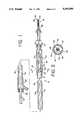
- FIG. 1is a longitudinal sectional view in partial cutaway of a low profile catheter assembly which incorporates a first presently preferred embodiment of this invention.
- FIG. 2is a cross-sectional view taken along line 2--2 of FIG. 1.
- FIG. 3is a fragmentary side view in partial cutaway of the guide wire included in the catheter assembly of FIG. 1.
- FIG. 4is a cross-sectional view taken along line 4--4 of FIG. 3.
- FIG. 5is a longitudinal sectional view of portions of a low profile catheter assembly which incorporates a second preferred embodiment of this invention.
- FIG. 6is a cross sectional view taken along line 6--6 of FIG. 5.
- FIG. 1shows a longitudinal sectional view of a low profile catheter assembly 10.
- the catheter assembly 10includes a catheter having a catheter shaft 12 which defines a proximal end 14 and a distal end 16.
- the catheter shaft 12is torsionally rigid and is formed of a ferrous metal alloy.
- the distal end 16 of the shaft 12carries a means for increasing the lumen size of a blood vessel in which the shaft 12 is placed.
- the lumen size increasing meansincludes an inflatable balloon 20 which is sealed at its proximal end to an outer tube 22 and at its distal end to an inner tube 24.
- the outer tube 24is in turn sealed to the distal end of the shaft 12.
- the inner tube 24extends axially through the balloon 20 and is sealed at its proximal end to a necked down portion of the shaft 12.
- this inventionis not limited to use with balloon type lumen size increasing means. Rather, it can also be adapted for use with other means for performing this function, such as devices including lasers or cutting, scraping or abrading edges.
- the inner tube 24is formed of high density polyethylene and has an outer diameter of 0.016 inch and a wall thickness of 0.0025 inch.
- the balloon 20can be formed of any conventional material such as a polyolefin copolymer in a thickness of 0.001-0.003 inches, depending on balloon diameter, and the outer tube 22 can be formed of a material such as high density polyethylene having an outer diameter of 0.026 inch and a wall thickness of 0.003 inch.
- the shaft 12can be formed from 304 stainless steel with an outer diameter of 0.026 inch and a wall thickness of 0.0035 inch.
- FIGS. 1 and 3show two views of a guide wire 30 that is mounted inside the shaft 12 as part of the catheter assembly 10.
- the guide wire 30defines a proximal end 32 and a distal end 34.
- the distal end 34forms a flexible end portion 36 that is configured to follow a blood vessel without damaging the walls of the vessel.
- the guide wire 30defines a keyed portion 38 which defines a pair of opposed flats 40 as shown in FIG. 2.
- the keyed portion 38is positioned in FIG. 1 near the distal end 16 of the shaft 12.
- the guide wire 30defines a region 42 extending proximally of the keyed portion 38 to the proximal end 32. This region 42 is sized no larger than the keyed portion 38, and in this embodiment is of reduced diameter as compared with the keyed portion 38.
- the guide wire 30defines an enlarged region 44 which is positioned immediately distally of the keyed portion 38. The transition between the enlarged region 44 and the keyed portion 38 is formed by transverse shoulder 48.
- the maximum diameter of the guide wire 30is defined at the flexible end portion 36.
- This flexible end portion 36includes a coil spring 50 which is brazed at each end to the guide wire 30 as indicated at reference numeral 52.
- the distal end 34 of the guide wire 30defines an enlarged end 54 sized to fit within the coil spring 50. Proximally of the enlarged end 54 is a neck region 56, shaped as shown in FIG. 4.
- the guide wire 30is formed of a solid main wire which can be formed of a ferrous alloy such as 304 stainless steel.
- the coil spring 50can for example be formed of a radiopaque wire having a diameter of 0.002 inches.
- the flats 40 in this embodimenthave an axial length of 15 cm, though flats 40 may also be used which are less than 10 cm in length.
- the catheter 10includes means for transmitting torque from the shaft 12 to the guide wire 30 and allowing axial movement therebetween.
- the torque transmitting meansis implemented as a keyed sleeve 64 which is secured to the distal end of the shaft 12 by a transversely oriented plate 60.
- the plate 60 and the sleeve 64are integrally formed with the shaft 12.
- the plate 60defines two openings 62 which are provided to pass an inflating fluid between the interior of the shaft 12 and the balloon 20.
- the sleeve 64defines an interior opening 66 which is other than round in cross section.
- the opening 66defines a pair of flats 68 which are shaped to engage the flats 40 so as to prevent relative rotation between the shaft 12 and the guide wire 30.
- the fit between the keyed portion 38 of the guide wire 30 and the opening 66 of the sleeve 64is a sliding fit that allows the guide wire 30 to be moved axially with respect to the catheter shaft 12.
- An inflation manifold 80is secured to the proximal end 14 of the shaft 12 to accommodate introduction of an inflating fluid into the interior of the shaft 12.
- This inflation manifold 80can be connected in a conventional manner to a source of pressurized inflating fluid (not shown) when the balloon 20 is to be inflated.
- the inflation manifold 80also functions as a means for applying torque to the proximal end 14 of the shaft 12. In use, the inflation manifold 80 can be rotated to rotate the shaft 12 and thereby apply rotating torques to the keyed portion 38 of the guide wire 30.
- a seal 82is provided on the inflation manifold 80 to prevent the release of inflating fluid around the guide wire 30. This seal 82 accommodates relative axial movement between the guide wire 30 and the shaft 12.
- the distal end 34 of the guide wire 30is provided with a prebent curvature (not shown), and the guide wire 30 is assembled with the shaft 12 as shown in FIG. 1. This assembly is then inserted in the conventional manner into the vascular system of a patient.
- the guide wire 30is used to guide the balloon 20 into the desired arterial branch. This is done by advancing the distal end 34 of the guide wire 30 into the desired arterial branch.
- the shaft 12is positioned to engage the sleeve 64 with the keyed portion 38, and then the inflation manifold 80 is manually rotated.
- the shaft 12is torsionally rigid as explained above, and rotational movement applied to the proximal end 14 is transmitted substantially completely to the distal end 16, where it is applied to the keyed portion 38 of the guide wire 30.
- the portion of the guide wire 30 between the keyed portion 38 and the distal end 34has sufficient torsional rigidity to rotate the distal end 34 of the guide wire 30 smoothly and reliably.
- the coil spring 50is formed of a radiopaque alloy including a metal such as platinum to allow the position of the coil spring 50 to be visualized on a flouriscope during the steering operation.
- the shaft 12 and guide wire 30cooperate to provide an easily steerable guide wire 30 which is nevertheless extremely small in diameter. Because the shaft 12 itself transmits torque to the keyed portion 38, the torsional rigidity of the guide wire proximal to the keyed portion 38 may be low with-out interfering with the ease with which the distal end 34 may be rotated and steered. Thus, this invention has particular advantages in extremely small diameter catheters which by necessity require even smaller diameter guide wires (less than 0.020 inches in diameter), which may not be well suited to transmit torques effectively over a length of more than 150 cm. In the preferred embodiment described above the keyed region 38 is positioned approximately 12 inches proximally of the distal end 34. The overall length of the guide wire 30 is 175 cm or about 69 inches. Thus, the keyed portion 38 is spaced from the distal end 34 by no more than about 20 percent of the overall length of the guide wire 30.
- the catheter 10provides the important advantage that once the guide wire 30 has been used to advance the balloon 20 to a desired treatment site, the shaft 12 and the balloon 20 can be removed from the proximal end 32 of the guide wire 30, while leaving the guide wire 30 in place in the treatment site. This is possible because the region 42 proximal to the keyed portion 38 is sized to fit through the sleeve 64.
- a second catheterwhich may or may not be similar to the catheter shown in FIG. 1, may be advanced along the guide wire 30 directly to the original treatment site. Conventional extension wires may be used to facilitate the exchange.
- the cathetermay be designed such that the guide wire extends outside the catheter for the proximal portion of the catheter and is received into the catheter for only the distal 15-30 cm of the catheter.
- FIGS. 5 and 6show portions of a second preferred embodiment of the catheter assembly of this invention.
- This embodimentincludes a catheter 100 having a shaft that comprises a proximal tube 112 and a distal tube 114 which are rigidly secured together at a point about 11 cm from the distal end of the catheter 100 (at approximately the position of the plate 60 in the catheter 10).
- the proximal end of the proximal tube 112is secured to an inflation manifold (not shown) similar to the inflation manifold 80.
- the distal end of the distal tube 114carries a balloon (not shown) similar to the balloon 30.
- a spring carrier spyder 116is fixed to the distal tube 114, as for example by welding.
- the spyderdefines four fins 118 which support a tube 120 coaxially with the tube 114.
- the region between the tubes 120, 114forms four flow passages 122 that allow an inflation fluid to pass between the proximal and distal tubes 112, 114 for inflation of the balloon (not shown).
- Two coil springs 124, 126are mounted within the tube 120, each fixed at one end by a respective spring tab 128, 130 which is securely fixed in place on the tube 120. Both of the springs 124, 126 are formed of rectangular section spring wire, and they are wound in the same direction.
- a guide wire 132is positioned within the springs 124, 126, and the guide wire 132 may be configured at its proximal and distal ends (not shown) like the guide wire 30.
- the guide wire 132defines an enlarged cylindrical portion 134 which in this embodiment is at least 10 and preferably 15 cm in length.
- the enlarged cylindrical portion 134is sized to allow the catheter 100 to be removed from the proximal end of the guide wire 132 and to move longitudinally through the springs 124, 126 freely in the absence of relative rotation between the catheter 100 and the guide wire 132.
- the respective one of the springs 124, 126automatically grips the guide wire 132 to prevent any relative rotation between the catheter 100 and the guide wire 132.
- Right hand rotation of the catheter 100 with respect to the guide wire 132winds up the spring 124 and causes the spring 124 to seize the guide wire 132.
- left hand rotation of the catheter 100 with respect to the guide wire 132winds up the spring 126 and causes the spring 126 to seize the guide wire 132.
- both of the springs 124, 126automatically relax, thereby automatically freeing the guide wire for longitudinal movement in the catheter 100.
- the catheter 100 and guide wire 132can be used as described above such that the torsional rigidity of the catheter 100 applies torque to the guide wire 132 near the distal end of the guide wire 132.
- the proximal tube 112is formed of polyethylene, and the distal tube 114 is a stainless steel hypotube.
- the spring carrier spyderis also formed of stainless steel.
- the torque transmitting meansdoes not necessarily include opposed flats as described above. Rather, a wide range of geometries can be used as long as they achieve the dual purposes of allowing relative axial movement and transmitting torque.
- the distal end of the guide wire 30can be altered in configuration and components as desired. Of course, materials and dimensions can be modified as desired to suit the intended application.
Landscapes
- Health & Medical Sciences (AREA)
- Heart & Thoracic Surgery (AREA)
- Life Sciences & Earth Sciences (AREA)
- Animal Behavior & Ethology (AREA)
- Biomedical Technology (AREA)
- Anesthesiology (AREA)
- Hematology (AREA)
- Engineering & Computer Science (AREA)
- Vascular Medicine (AREA)
- General Health & Medical Sciences (AREA)
- Public Health (AREA)
- Veterinary Medicine (AREA)
- Child & Adolescent Psychology (AREA)
- Biophysics (AREA)
- Pulmonology (AREA)
- Media Introduction/Drainage Providing Device (AREA)
Abstract
Description
______________________________________ MEASUREMENT PREFERRED DIMENSION (inches) ______________________________________ D1 0.008 D2 0.0095 D3 0.0078 D4 0.0055 D5 0.100 L1 4.00 L2 7.00 L3 11.00 L4 11.93 L5 69. (175 cm) ______________________________________
Claims (53)
Priority Applications (7)
| Application Number | Priority Date | Filing Date | Title |
|---|---|---|---|
| US07/583,437US5195989A (en) | 1990-09-17 | 1990-09-17 | Low profile catheter for increasing lumen size of a blood vessel and guide wire therefor |
| AU85456/91AAU8545691A (en) | 1990-09-17 | 1991-09-13 | Low profile catheter and guidewire |
| JP3515690AJPH06500722A (en) | 1990-09-17 | 1991-09-13 | Small catheter and guidewire |
| CA002091779ACA2091779A1 (en) | 1990-09-17 | 1991-09-13 | Low profile catheter and guidewire |
| EP91917207AEP0648139A1 (en) | 1990-09-17 | 1991-09-13 | Low profile catheter and guidewire |
| PCT/US1991/006673WO1992004931A1 (en) | 1990-09-17 | 1991-09-13 | Low profile catheter and guidewire |
| US07/899,771US5292315A (en) | 1990-09-17 | 1992-06-17 | Low profile catheter for increasing lumen size of a blood vessel and guide wire therefor |
Applications Claiming Priority (1)
| Application Number | Priority Date | Filing Date | Title |
|---|---|---|---|
| US07/583,437US5195989A (en) | 1990-09-17 | 1990-09-17 | Low profile catheter for increasing lumen size of a blood vessel and guide wire therefor |
Related Child Applications (1)
| Application Number | Title | Priority Date | Filing Date |
|---|---|---|---|
| US07/899,771ContinuationUS5292315A (en) | 1990-09-17 | 1992-06-17 | Low profile catheter for increasing lumen size of a blood vessel and guide wire therefor |
Publications (1)
| Publication Number | Publication Date |
|---|---|
| US5195989Atrue US5195989A (en) | 1993-03-23 |
Family
ID=24333091
Family Applications (2)
| Application Number | Title | Priority Date | Filing Date |
|---|---|---|---|
| US07/583,437Expired - LifetimeUS5195989A (en) | 1990-09-17 | 1990-09-17 | Low profile catheter for increasing lumen size of a blood vessel and guide wire therefor |
| US07/899,771Expired - LifetimeUS5292315A (en) | 1990-09-17 | 1992-06-17 | Low profile catheter for increasing lumen size of a blood vessel and guide wire therefor |
Family Applications After (1)
| Application Number | Title | Priority Date | Filing Date |
|---|---|---|---|
| US07/899,771Expired - LifetimeUS5292315A (en) | 1990-09-17 | 1992-06-17 | Low profile catheter for increasing lumen size of a blood vessel and guide wire therefor |
Country Status (6)
| Country | Link |
|---|---|
| US (2) | US5195989A (en) |
| EP (1) | EP0648139A1 (en) |
| JP (1) | JPH06500722A (en) |
| AU (1) | AU8545691A (en) |
| CA (1) | CA2091779A1 (en) |
| WO (1) | WO1992004931A1 (en) |
Cited By (25)
| Publication number | Priority date | Publication date | Assignee | Title |
|---|---|---|---|---|
| US5257974A (en)* | 1992-08-19 | 1993-11-02 | Scimed Life Systems, Inc. | Performance enhancement adaptor for intravascular balloon catheter |
| US5292315A (en)* | 1990-09-17 | 1994-03-08 | Scimed Life Systems, Inc. | Low profile catheter for increasing lumen size of a blood vessel and guide wire therefor |
| US5312340A (en)* | 1992-03-17 | 1994-05-17 | Scimed Life Systems, Inc. | Balloon dilatation catheter having dual sealing plugs |
| US5378236A (en)* | 1992-05-15 | 1995-01-03 | C. R. Bard, Inc. | Balloon dilatation catheter with integral detachable guidewire |
| US5409470A (en)* | 1993-05-07 | 1995-04-25 | C. R. Bard, Inc. | Dilatation catheter and guidewire with threaded tip connection |
| US5417658A (en)* | 1992-03-17 | 1995-05-23 | Scimed Life Systems, Inc. | Balloon dilatation catheter having a torsionally soft component |
| US5441484A (en)* | 1992-03-17 | 1995-08-15 | Scimed Life Systems, Inc. | Balloon dilatation catheter having a free core wire |
| US5497785A (en)* | 1994-07-27 | 1996-03-12 | Cordis Corporation | Catheter advancing guidewire and method for making same |
| US5501668A (en)* | 1991-08-09 | 1996-03-26 | Boston Scientific Corporation | Angioplasty balloon catheter and adaptor |
| US5545136A (en)* | 1993-09-14 | 1996-08-13 | Berger; J. Lee | Grooved catheter director apparatus |
| US5605543A (en)* | 1994-03-10 | 1997-02-25 | Schneider (Usa) Inc. | Catheter having shaft of varying stiffness |
| USRE35523E (en)* | 1991-10-11 | 1997-06-03 | Berger; J. Lee | Percutaneous carpal tunnel plasty method |
| US5704926A (en)* | 1994-11-23 | 1998-01-06 | Navarre Biomedical, Ltd. | Flexible catheter |
| US20020177902A1 (en)* | 2001-05-22 | 2002-11-28 | Rioux Robert F. | Draining bodily fluids with a stent |
| US6514228B1 (en) | 1999-03-05 | 2003-02-04 | Scimed Life Systems, Inc. | Balloon catheter having high flow tip |
| US20040097878A1 (en)* | 1992-09-30 | 2004-05-20 | Anderson Jere R. | Distensible dilatation balloon with elastic stress response and manufacture thereof |
| US6790223B2 (en) | 2001-09-21 | 2004-09-14 | Scimed Life Systems, Inc. | Delivering a uretheral stent |
| US20040181287A1 (en)* | 2002-10-22 | 2004-09-16 | Scimed Life Systems | Male urethral stent device |
| US20040225372A1 (en)* | 2003-05-09 | 2004-11-11 | Gellman Barry N. | Stricture retractor |
| US20140088560A1 (en)* | 2011-03-30 | 2014-03-27 | Cornell University | Intra-luminal access apparatus and methods of using the same |
| US20160038726A1 (en)* | 2009-06-05 | 2016-02-11 | Entellus Medical, Inc. | Method and articles for treating the sinus system |
| US9872981B2 (en) | 2010-09-28 | 2018-01-23 | Biotrace Medical, Inc. | Device and method for positioning an electrode in a body cavity |
| US10124162B2 (en) | 2010-09-28 | 2018-11-13 | The Board Of Trustees Of The Leland Stanford Junior University | Device and method for positioning an electrode in tissue |
| US10232170B2 (en) | 2014-05-09 | 2019-03-19 | Biotrace Medical, Inc. | Device and method for positioning an electrode in a body cavity |
| US10363402B2 (en) | 2009-06-05 | 2019-07-30 | Entellus Medical, Inc. | Sinus dilation catheter |
Families Citing this family (5)
| Publication number | Priority date | Publication date | Assignee | Title |
|---|---|---|---|---|
| US5628761A (en)* | 1994-07-08 | 1997-05-13 | Rizik; David G. | Guide wire passage creation device |
| WO2000032105A1 (en) | 1998-11-25 | 2000-06-08 | Ball Semiconductor, Inc. | Monitor for interventional procedures |
| JP4473266B2 (en)* | 2004-03-15 | 2010-06-02 | テルモ株式会社 | Guide wire assembly |
| US20060136034A1 (en)* | 2004-12-20 | 2006-06-22 | Vascular Architects, Inc. | Delivery catheter and method |
| US8808345B2 (en)* | 2008-12-31 | 2014-08-19 | Medtronic Ardian Luxembourg S.A.R.L. | Handle assemblies for intravascular treatment devices and associated systems and methods |
Citations (27)
| Publication number | Priority date | Publication date | Assignee | Title |
|---|---|---|---|---|
| US2819718A (en)* | 1953-07-16 | 1958-01-14 | Isidore H Goldman | Drainage tube |
| US4004588A (en)* | 1975-05-21 | 1977-01-25 | Wrightson Nma Limited | Apparatus for flushing ova from cows or mares |
| US4166468A (en)* | 1977-08-05 | 1979-09-04 | Haynie Louis D | Apparatus for endotracheal and esophageal intubation |
| US4413989A (en)* | 1980-09-08 | 1983-11-08 | Angiomedics Corporation | Expandable occlusion apparatus |
| US4580573A (en)* | 1983-10-20 | 1986-04-08 | Medical Device Development Corporation, Inc. | Catheter introducer |
| US4582181A (en)* | 1983-08-12 | 1986-04-15 | Advanced Cardiovascular Systems, Inc. | Steerable dilatation catheter |
| US4606347A (en)* | 1983-03-25 | 1986-08-19 | Thomas J. Fogarty | Inverted balloon catheter having sealed through lumen |
| US4616653A (en)* | 1985-07-30 | 1986-10-14 | Advanced Cardiovascular Systems, Inc. | Balloon dilatation catheter with advanceable non-removable guide wire |
| US4641654A (en)* | 1985-07-30 | 1987-02-10 | Advanced Cardiovascular Systems, Inc. | Steerable balloon dilatation catheter assembly having dye injection and pressure measurement capabilities |
| US4646742A (en)* | 1986-01-27 | 1987-03-03 | Angiomedics Incorporated | Angioplasty catheter assembly |
| US4696667A (en)* | 1986-03-20 | 1987-09-29 | Helmut Masch | Intravascular catheter and method |
| US4721117A (en)* | 1986-04-25 | 1988-01-26 | Advanced Cardiovascular Systems, Inc. | Torsionally stabilized guide wire with outer jacket |
| US4743647A (en)* | 1985-08-02 | 1988-05-10 | Amoco Corporation | Prepreg resin from aromatic bismaleimide and ethylenically unsaturated coreactant |
| US4771778A (en)* | 1987-01-06 | 1988-09-20 | Advanced Cardiovascular Systems, Inc. | Steerable low profile balloon dilatation catheter |
| US4793350A (en)* | 1987-01-06 | 1988-12-27 | Advanced Cardiovascular Systems, Inc. | Liquid filled low profile dilatation catheter |
| US4827941A (en)* | 1987-12-23 | 1989-05-09 | Advanced Cardiovascular Systems, Inc. | Extendable guidewire for cardiovascular procedures |
| US4838268A (en)* | 1988-03-07 | 1989-06-13 | Scimed Life Systems, Inc. | Non-over-the wire balloon catheter |
| US4841976A (en)* | 1987-12-17 | 1989-06-27 | Schneider-Shiley (Usa) Inc. | Steerable catheter guide |
| US4875489A (en)* | 1987-08-14 | 1989-10-24 | Advanced Cardiovascular Systems, Inc. | Extendable guidewire |
| US4917666A (en)* | 1988-11-14 | 1990-04-17 | Medtronic Versaflex, Inc. | Steerable thru-lumen catheter |
| US4917103A (en)* | 1985-09-18 | 1990-04-17 | C. R. Bard, Inc. | Guide wire extension |
| US4922923A (en)* | 1985-09-18 | 1990-05-08 | C. R. Bard, Inc. | Method for effecting a catheter exchange |
| US4932959A (en)* | 1988-12-01 | 1990-06-12 | Advanced Cardiovascular Systems, Inc. | Vascular catheter with releasably secured guidewire |
| US4932413A (en)* | 1989-03-13 | 1990-06-12 | Schneider (Usa), Inc. | Guidewire exchange catheter |
| US4934380A (en)* | 1987-11-27 | 1990-06-19 | Boston Scientific Corporation | Medical guidewire |
| US5045061A (en)* | 1990-02-02 | 1991-09-03 | C. R. Bard, Inc. | Balloon catheter and locking guidewire system |
| US5055109A (en)* | 1989-10-05 | 1991-10-08 | Advanced Cardiovascular Systems, Inc. | Torque transmitting assembly for intravascular devices |
Family Cites Families (6)
| Publication number | Priority date | Publication date | Assignee | Title |
|---|---|---|---|---|
| US4045061A (en)* | 1976-04-14 | 1977-08-30 | Fierro Mary M | Decorative article forming support |
| US4116468A (en)* | 1977-03-18 | 1978-09-26 | Marten Hilda C | Register tape editor |
| DE3815172C1 (en)* | 1988-05-04 | 1990-03-22 | Rasmussen Gmbh, 6457 Maintal, De | |
| US5114403A (en)* | 1989-09-15 | 1992-05-19 | Eclipse Surgical Technologies, Inc. | Catheter torque mechanism |
| US5195989A (en)* | 1990-09-17 | 1993-03-23 | Scimed Life Systems, Inc. | Low profile catheter for increasing lumen size of a blood vessel and guide wire therefor |
| US5135483A (en)* | 1991-07-22 | 1992-08-04 | Dow Corning Wright Corporation | Atherectomy device with a removable drive system |
- 1990
- 1990-09-17USUS07/583,437patent/US5195989A/ennot_activeExpired - Lifetime
- 1991
- 1991-09-13AUAU85456/91Apatent/AU8545691A/ennot_activeAbandoned
- 1991-09-13CACA002091779Apatent/CA2091779A1/ennot_activeAbandoned
- 1991-09-13WOPCT/US1991/006673patent/WO1992004931A1/ennot_activeApplication Discontinuation
- 1991-09-13EPEP91917207Apatent/EP0648139A1/ennot_activeWithdrawn
- 1991-09-13JPJP3515690Apatent/JPH06500722A/enactivePending
- 1992
- 1992-06-17USUS07/899,771patent/US5292315A/ennot_activeExpired - Lifetime
Patent Citations (27)
| Publication number | Priority date | Publication date | Assignee | Title |
|---|---|---|---|---|
| US2819718A (en)* | 1953-07-16 | 1958-01-14 | Isidore H Goldman | Drainage tube |
| US4004588A (en)* | 1975-05-21 | 1977-01-25 | Wrightson Nma Limited | Apparatus for flushing ova from cows or mares |
| US4166468A (en)* | 1977-08-05 | 1979-09-04 | Haynie Louis D | Apparatus for endotracheal and esophageal intubation |
| US4413989A (en)* | 1980-09-08 | 1983-11-08 | Angiomedics Corporation | Expandable occlusion apparatus |
| US4606347A (en)* | 1983-03-25 | 1986-08-19 | Thomas J. Fogarty | Inverted balloon catheter having sealed through lumen |
| US4582181A (en)* | 1983-08-12 | 1986-04-15 | Advanced Cardiovascular Systems, Inc. | Steerable dilatation catheter |
| US4580573A (en)* | 1983-10-20 | 1986-04-08 | Medical Device Development Corporation, Inc. | Catheter introducer |
| US4616653A (en)* | 1985-07-30 | 1986-10-14 | Advanced Cardiovascular Systems, Inc. | Balloon dilatation catheter with advanceable non-removable guide wire |
| US4641654A (en)* | 1985-07-30 | 1987-02-10 | Advanced Cardiovascular Systems, Inc. | Steerable balloon dilatation catheter assembly having dye injection and pressure measurement capabilities |
| US4743647A (en)* | 1985-08-02 | 1988-05-10 | Amoco Corporation | Prepreg resin from aromatic bismaleimide and ethylenically unsaturated coreactant |
| US4922923A (en)* | 1985-09-18 | 1990-05-08 | C. R. Bard, Inc. | Method for effecting a catheter exchange |
| US4917103A (en)* | 1985-09-18 | 1990-04-17 | C. R. Bard, Inc. | Guide wire extension |
| US4646742A (en)* | 1986-01-27 | 1987-03-03 | Angiomedics Incorporated | Angioplasty catheter assembly |
| US4696667A (en)* | 1986-03-20 | 1987-09-29 | Helmut Masch | Intravascular catheter and method |
| US4721117A (en)* | 1986-04-25 | 1988-01-26 | Advanced Cardiovascular Systems, Inc. | Torsionally stabilized guide wire with outer jacket |
| US4771778A (en)* | 1987-01-06 | 1988-09-20 | Advanced Cardiovascular Systems, Inc. | Steerable low profile balloon dilatation catheter |
| US4793350A (en)* | 1987-01-06 | 1988-12-27 | Advanced Cardiovascular Systems, Inc. | Liquid filled low profile dilatation catheter |
| US4875489A (en)* | 1987-08-14 | 1989-10-24 | Advanced Cardiovascular Systems, Inc. | Extendable guidewire |
| US4934380A (en)* | 1987-11-27 | 1990-06-19 | Boston Scientific Corporation | Medical guidewire |
| US4841976A (en)* | 1987-12-17 | 1989-06-27 | Schneider-Shiley (Usa) Inc. | Steerable catheter guide |
| US4827941A (en)* | 1987-12-23 | 1989-05-09 | Advanced Cardiovascular Systems, Inc. | Extendable guidewire for cardiovascular procedures |
| US4838268A (en)* | 1988-03-07 | 1989-06-13 | Scimed Life Systems, Inc. | Non-over-the wire balloon catheter |
| US4917666A (en)* | 1988-11-14 | 1990-04-17 | Medtronic Versaflex, Inc. | Steerable thru-lumen catheter |
| US4932959A (en)* | 1988-12-01 | 1990-06-12 | Advanced Cardiovascular Systems, Inc. | Vascular catheter with releasably secured guidewire |
| US4932413A (en)* | 1989-03-13 | 1990-06-12 | Schneider (Usa), Inc. | Guidewire exchange catheter |
| US5055109A (en)* | 1989-10-05 | 1991-10-08 | Advanced Cardiovascular Systems, Inc. | Torque transmitting assembly for intravascular devices |
| US5045061A (en)* | 1990-02-02 | 1991-09-03 | C. R. Bard, Inc. | Balloon catheter and locking guidewire system |
Cited By (49)
| Publication number | Priority date | Publication date | Assignee | Title |
|---|---|---|---|---|
| US6033381A (en)* | 1989-09-06 | 2000-03-07 | Boston Scientific Corporation | Angioplasty balloon catheter and adaptor |
| US5800391A (en)* | 1989-09-06 | 1998-09-01 | Boston Scientific Corporation | Angioplasty balloon catheter and adaptor |
| US5292315A (en)* | 1990-09-17 | 1994-03-08 | Scimed Life Systems, Inc. | Low profile catheter for increasing lumen size of a blood vessel and guide wire therefor |
| US5501668A (en)* | 1991-08-09 | 1996-03-26 | Boston Scientific Corporation | Angioplasty balloon catheter and adaptor |
| USRE35523E (en)* | 1991-10-11 | 1997-06-03 | Berger; J. Lee | Percutaneous carpal tunnel plasty method |
| US5417658A (en)* | 1992-03-17 | 1995-05-23 | Scimed Life Systems, Inc. | Balloon dilatation catheter having a torsionally soft component |
| US5441484A (en)* | 1992-03-17 | 1995-08-15 | Scimed Life Systems, Inc. | Balloon dilatation catheter having a free core wire |
| US5312340A (en)* | 1992-03-17 | 1994-05-17 | Scimed Life Systems, Inc. | Balloon dilatation catheter having dual sealing plugs |
| US5378236A (en)* | 1992-05-15 | 1995-01-03 | C. R. Bard, Inc. | Balloon dilatation catheter with integral detachable guidewire |
| US5338300A (en)* | 1992-08-19 | 1994-08-16 | Scimed Life Systems, Inc. | Performance enhancement adaptor for intravascular balloon catheter |
| US5257974A (en)* | 1992-08-19 | 1993-11-02 | Scimed Life Systems, Inc. | Performance enhancement adaptor for intravascular balloon catheter |
| US20040097878A1 (en)* | 1992-09-30 | 2004-05-20 | Anderson Jere R. | Distensible dilatation balloon with elastic stress response and manufacture thereof |
| US5409470A (en)* | 1993-05-07 | 1995-04-25 | C. R. Bard, Inc. | Dilatation catheter and guidewire with threaded tip connection |
| US5545136A (en)* | 1993-09-14 | 1996-08-13 | Berger; J. Lee | Grooved catheter director apparatus |
| US5743876A (en)* | 1994-03-10 | 1998-04-28 | Schneider (Usa) Inc | Catheter having shaft of varying stiffness |
| US5605543A (en)* | 1994-03-10 | 1997-02-25 | Schneider (Usa) Inc. | Catheter having shaft of varying stiffness |
| US5497785A (en)* | 1994-07-27 | 1996-03-12 | Cordis Corporation | Catheter advancing guidewire and method for making same |
| US5704926A (en)* | 1994-11-23 | 1998-01-06 | Navarre Biomedical, Ltd. | Flexible catheter |
| US6514228B1 (en) | 1999-03-05 | 2003-02-04 | Scimed Life Systems, Inc. | Balloon catheter having high flow tip |
| US7691078B2 (en) | 2001-05-22 | 2010-04-06 | Boston Scientific Scimed, Inc. | Draining bodily fluids with a stent |
| US20020177902A1 (en)* | 2001-05-22 | 2002-11-28 | Rioux Robert F. | Draining bodily fluids with a stent |
| US7918815B2 (en) | 2001-05-22 | 2011-04-05 | Boston Scientific Scimed, Inc. | Draining bodily fluids with a stent |
| US20100152862A1 (en)* | 2001-05-22 | 2010-06-17 | Boston Scientific Scimed, Inc. | Draining Bodily Fluids With A Stent |
| US6981964B2 (en) | 2001-05-22 | 2006-01-03 | Boston Scientific Scimed, Inc. | Draining bodily fluids with a stent |
| US6790223B2 (en) | 2001-09-21 | 2004-09-14 | Scimed Life Systems, Inc. | Delivering a uretheral stent |
| US7112226B2 (en) | 2002-10-22 | 2006-09-26 | Boston Scientific Scimed, Inc. | Male urethral stent device |
| US7527651B2 (en) | 2002-10-22 | 2009-05-05 | Boston Scientific Scimed, Inc. | Male urethral stent device |
| US20060276909A1 (en)* | 2002-10-22 | 2006-12-07 | Boston Scientific Scimed, Inc. | Male urethral stent device |
| US20040181287A1 (en)* | 2002-10-22 | 2004-09-16 | Scimed Life Systems | Male urethral stent device |
| US7651529B2 (en) | 2003-05-09 | 2010-01-26 | Boston Scientific Scimed, Inc. | Stricture retractor |
| US20040225372A1 (en)* | 2003-05-09 | 2004-11-11 | Gellman Barry N. | Stricture retractor |
| US12274847B2 (en) | 2009-06-05 | 2025-04-15 | Stryker Corporation | Method and articles for treating the sinus system |
| US11083878B2 (en) | 2009-06-05 | 2021-08-10 | Entellus Medical, Inc. | Method and articles for treating the sinus system |
| US12064580B2 (en) | 2009-06-05 | 2024-08-20 | Entellus Medical, Inc. | Method and articles for treating the sinus system |
| US10022525B2 (en)* | 2009-06-05 | 2018-07-17 | Entellus Medical, Inc. | Method and articles for treating the sinus system |
| US20160038726A1 (en)* | 2009-06-05 | 2016-02-11 | Entellus Medical, Inc. | Method and articles for treating the sinus system |
| US11541214B2 (en) | 2009-06-05 | 2023-01-03 | Entellus Medical, Inc. | Balloon dilation catheter for use in sinus passageways |
| US10363402B2 (en) | 2009-06-05 | 2019-07-30 | Entellus Medical, Inc. | Sinus dilation catheter |
| US10369337B2 (en) | 2009-06-05 | 2019-08-06 | Entellus Medical, Inc. | Balloon dilation catheter for use in sinus passageways |
| US10561829B2 (en) | 2009-06-05 | 2020-02-18 | Entellus Medical, Inc. | Method and articles for treating the sinus system |
| US10835723B2 (en) | 2009-06-05 | 2020-11-17 | Entellus Medical, Inc. | Method and articles for treating the sinus system |
| US11090472B2 (en) | 2009-06-05 | 2021-08-17 | Entellus Medical, Inc. | Method and articles for treating the sinus system |
| US10124162B2 (en) | 2010-09-28 | 2018-11-13 | The Board Of Trustees Of The Leland Stanford Junior University | Device and method for positioning an electrode in tissue |
| US12102821B2 (en) | 2010-09-28 | 2024-10-01 | The Board Of Trustees Of The Leland Stanford Junior University | Device and method for positioning an electrode in tissue |
| US9872981B2 (en) | 2010-09-28 | 2018-01-23 | Biotrace Medical, Inc. | Device and method for positioning an electrode in a body cavity |
| US20140088560A1 (en)* | 2011-03-30 | 2014-03-27 | Cornell University | Intra-luminal access apparatus and methods of using the same |
| US10232170B2 (en) | 2014-05-09 | 2019-03-19 | Biotrace Medical, Inc. | Device and method for positioning an electrode in a body cavity |
| US12076555B2 (en) | 2014-05-09 | 2024-09-03 | Merit Medical Systems, Inc. | Device and method for positioning an electrode in a body cavity |
| US10953223B2 (en) | 2014-05-09 | 2021-03-23 | Biotrace Medical, Inc. | Device and method for positioning an electrode in a body cavity |
Also Published As
| Publication number | Publication date |
|---|---|
| WO1992004931A1 (en) | 1992-04-02 |
| US5292315A (en) | 1994-03-08 |
| AU8545691A (en) | 1992-04-15 |
| EP0648139A1 (en) | 1995-04-19 |
| JPH06500722A (en) | 1994-01-27 |
| EP0648139A4 (en) | 1992-04-02 |
| CA2091779A1 (en) | 1992-03-18 |
Similar Documents
| Publication | Publication Date | Title |
|---|---|---|
| US5195989A (en) | Low profile catheter for increasing lumen size of a blood vessel and guide wire therefor | |
| US4917088A (en) | Balloon dilation probe | |
| US5104376A (en) | Torsionally rigid balloon dilatation probe | |
| US5102390A (en) | Microdilatation probe and system for performing angioplasty in highly stenosed blood vessels | |
| US4719924A (en) | Small diameter steerable guidewire with adjustable tip | |
| US5269757A (en) | Catheter with integral steerable guidewire having linear to rotary movement | |
| US5449343A (en) | Steerable dilatation catheter | |
| US5141518A (en) | Angioplasty catheter with close-fitting guidewire and tube | |
| US5281200A (en) | Multiple component balloon catheter system and stenosis treatment procedure | |
| US5409470A (en) | Dilatation catheter and guidewire with threaded tip connection | |
| US5836957A (en) | Large volume atherectomy device | |
| EP0994742B1 (en) | Variable stiffness angioplasty guidewire | |
| US5060660A (en) | Steerable extendable guidewire with adjustable tip | |
| US5265622A (en) | Guidewire having radially expandable member and method for guiding and advancing a catheter using the same | |
| US20030040769A1 (en) | Single lumen rapid-exchange catheter | |
| EP0462801B1 (en) | Fixed wire dilation catheter with distal twistable segment | |
| JPH02224767A (en) | Operable type expansion cathetel | |
| US5378236A (en) | Balloon dilatation catheter with integral detachable guidewire | |
| JPH04261669A (en) | Pulse tube forming inflated balloon type catheter/guide wire system | |
| JP3638304B2 (en) | Intravascular catheter | |
| JP3989917B2 (en) | Balloon catheter guide wire assembly |
Legal Events
| Date | Code | Title | Description |
|---|---|---|---|
| AS | Assignment | Owner name:SCIMED LIFE SYSTEMS, INC., MINNESOTA Free format text:ASSIGNMENT OF ASSIGNORS INTEREST.;ASSIGNOR:EUTENEUER, CHARLES L.;REEL/FRAME:005453/0671 Effective date:19900911 | |
| STCF | Information on status: patent grant | Free format text:PATENTED CASE | |
| CC | Certificate of correction | ||
| FEPP | Fee payment procedure | Free format text:PAYOR NUMBER ASSIGNED (ORIGINAL EVENT CODE: ASPN); ENTITY STATUS OF PATENT OWNER: LARGE ENTITY | |
| FPAY | Fee payment | Year of fee payment:4 | |
| FEPP | Fee payment procedure | Free format text:PAYER NUMBER DE-ASSIGNED (ORIGINAL EVENT CODE: RMPN); ENTITY STATUS OF PATENT OWNER: LARGE ENTITY | |
| FPAY | Fee payment | Year of fee payment:8 | |
| FEPP | Fee payment procedure | Free format text:PAYOR NUMBER ASSIGNED (ORIGINAL EVENT CODE: ASPN); ENTITY STATUS OF PATENT OWNER: LARGE ENTITY | |
| FPAY | Fee payment | Year of fee payment:12 | |
| AS | Assignment | Owner name:BOSTON SCIENTIFIC SCIMED, INC., MINNESOTA Free format text:CHANGE OF NAME;ASSIGNOR:SCIMED LIFE SYSTEMS, INC.;REEL/FRAME:018505/0868 Effective date:20050101 Owner name:BOSTON SCIENTIFIC SCIMED, INC.,MINNESOTA Free format text:CHANGE OF NAME;ASSIGNOR:SCIMED LIFE SYSTEMS, INC.;REEL/FRAME:018505/0868 Effective date:20050101 |