US5195563A - Flexible hose and fittings - Google Patents
Flexible hose and fittingsDownload PDFInfo
- Publication number
- US5195563A US5195563AUS07/818,291US81829192AUS5195563AUS 5195563 AUS5195563 AUS 5195563AUS 81829192 AUS81829192 AUS 81829192AUS 5195563 AUS5195563 AUS 5195563A
- Authority
- US
- United States
- Prior art keywords
- hose
- portions
- attachment
- ribs
- ribbed
- Prior art date
- Legal status (The legal status is an assumption and is not a legal conclusion. Google has not performed a legal analysis and makes no representation as to the accuracy of the status listed.)
- Expired - Lifetime
Links
- 230000009182swimmingEffects0.000claimsdescription11
- 239000000463materialSubstances0.000claimsdescription8
- 238000005188flotationMethods0.000abstractdescription17
- 238000004140cleaningMethods0.000description10
- 229920003023plasticPolymers0.000description7
- 239000004033plasticSubstances0.000description7
- XLYOFNOQVPJJNP-UHFFFAOYSA-NwaterSubstancesOXLYOFNOQVPJJNP-UHFFFAOYSA-N0.000description6
- 238000003780insertionMethods0.000description5
- 230000037431insertionEffects0.000description5
- 230000008878couplingEffects0.000description3
- 238000010168coupling processMethods0.000description3
- 238000005859coupling reactionMethods0.000description3
- 238000000034methodMethods0.000description3
- 238000010276constructionMethods0.000description2
- 238000001914filtrationMethods0.000description2
- 238000004519manufacturing processMethods0.000description2
- 239000004743PolypropyleneSubstances0.000description1
- 230000009471actionEffects0.000description1
- 238000009411base constructionMethods0.000description1
- 229920002457flexible plasticPolymers0.000description1
- 238000009434installationMethods0.000description1
- 230000007246mechanismEffects0.000description1
- -1polypropylenePolymers0.000description1
- 229920001155polypropylenePolymers0.000description1
- 238000005096rolling processMethods0.000description1
- 238000003892spreadingMethods0.000description1
- 230000007480spreadingEffects0.000description1
Images

Classifications
- F—MECHANICAL ENGINEERING; LIGHTING; HEATING; WEAPONS; BLASTING
- F16—ENGINEERING ELEMENTS AND UNITS; GENERAL MEASURES FOR PRODUCING AND MAINTAINING EFFECTIVE FUNCTIONING OF MACHINES OR INSTALLATIONS; THERMAL INSULATION IN GENERAL
- F16L—PIPES; JOINTS OR FITTINGS FOR PIPES; SUPPORTS FOR PIPES, CABLES OR PROTECTIVE TUBING; MEANS FOR THERMAL INSULATION IN GENERAL
- F16L11/00—Hoses, i.e. flexible pipes
- F16L11/14—Hoses, i.e. flexible pipes made of rigid material, e.g. metal or hard plastics
- F16L11/15—Hoses, i.e. flexible pipes made of rigid material, e.g. metal or hard plastics corrugated
- E—FIXED CONSTRUCTIONS
- E04—BUILDING
- E04H—BUILDINGS OR LIKE STRUCTURES FOR PARTICULAR PURPOSES; SWIMMING OR SPLASH BATHS OR POOLS; MASTS; FENCING; TENTS OR CANOPIES, IN GENERAL
- E04H4/00—Swimming or splash baths or pools
- E04H4/14—Parts, details or accessories not otherwise provided for
- E04H4/16—Parts, details or accessories not otherwise provided for specially adapted for cleaning
- F—MECHANICAL ENGINEERING; LIGHTING; HEATING; WEAPONS; BLASTING
- F16—ENGINEERING ELEMENTS AND UNITS; GENERAL MEASURES FOR PRODUCING AND MAINTAINING EFFECTIVE FUNCTIONING OF MACHINES OR INSTALLATIONS; THERMAL INSULATION IN GENERAL
- F16L—PIPES; JOINTS OR FITTINGS FOR PIPES; SUPPORTS FOR PIPES, CABLES OR PROTECTIVE TUBING; MEANS FOR THERMAL INSULATION IN GENERAL
- F16L11/00—Hoses, i.e. flexible pipes
- F16L11/04—Hoses, i.e. flexible pipes made of rubber or flexible plastics
- F16L11/12—Hoses, i.e. flexible pipes made of rubber or flexible plastics with arrangements for particular purposes, e.g. specially profiled, with protecting layer, heated, electrically conducting
- F16L11/133—Hoses, i.e. flexible pipes made of rubber or flexible plastics with arrangements for particular purposes, e.g. specially profiled, with protecting layer, heated, electrically conducting buoyant
- Y—GENERAL TAGGING OF NEW TECHNOLOGICAL DEVELOPMENTS; GENERAL TAGGING OF CROSS-SECTIONAL TECHNOLOGIES SPANNING OVER SEVERAL SECTIONS OF THE IPC; TECHNICAL SUBJECTS COVERED BY FORMER USPC CROSS-REFERENCE ART COLLECTIONS [XRACs] AND DIGESTS
- Y10—TECHNICAL SUBJECTS COVERED BY FORMER USPC
- Y10S—TECHNICAL SUBJECTS COVERED BY FORMER USPC CROSS-REFERENCE ART COLLECTIONS [XRACs] AND DIGESTS
- Y10S285/00—Pipe joints or couplings
- Y10S285/903—Corrugated
Definitions
- This inventionrelates to hoses for swimming pool cleaners and the like, and specifically to a hose having simple fittings to cause the hose to float, to assist the hose in moving across the pool bottom, or to attach the hose to other pool equipment.
- Typical swimming pool cleanersare connected to the filtration system of the pool by a long, flexible hose.
- Some pool cleanersinclude a surface unit connected by flexible hoses to both the filter outlet and to an underwater cleaning head.
- One such mechanismis disclosed in U.S. Pat. No. 4,652,366.
- the hoses used in pool cleanersmay be composed of various materials. Plastic is popular because of relatively low cost, flexibility and durability.
- An advantageous base constructionis a thin-walled plastic tube formed as a series of alternating ribs and grooves giving the hose wall strength while preserving the ability to flex and bend.
- various fittingsare attached to the hose used in a swimming pool cleaner.
- end couplingsthat typically have been threaded, adhesively secured or sealed to the hose, and accessories mounted on the hose, such as floats and wheeled attachments for rolling along the walls of the pool.
- the present inventionprovides a simplified hose construction that simply and inexpensively accommodates a variety of hose attachments and facilitates both the manufacture of the attachments and the assembly of the attachments on the hose.
- the hosecomprises a plurality of ribbed portions that alternate with and are joined together by relatively short smooth portions.
- the ribbed portionsprovide the desired flexibility and a novel mounting feature for end fittings.
- the smooth portionsprovide mounting areas for attachments such as flotation cuffs or wheel cages that are fitted around the hose.
- the ribbed portionsare relatively long, constituting most of the length of the hose, and the smooth portions are relatively short, having approximately the length of the attachments so that the ribs on opposite sides of an attachment will form stops for holding the attachment in place on the hose.
- the attachmentsinclude generally cylindrical body portions that are divided longitudinally along one side to form a slot that is narrower than the outside diameter of the smooth portions. The slot permits assembly of the attachment by flexing of the hose, or of the attachment, or of both, after which the resilience of one or both of the parts restores the parts to their normal shapes with the attachment assembled on the hose.
- Flotation cuffs for use in the present inventionare made of buoyant material and preferably are resiliently flexible for installation on the hose.
- Wheel cages for use on the inventionhave bodies that are made of resiliently flexible plastic, preferably non-buoyant, and have outwardly projecting fins that are arranged in pairs around the periphery of the cuff. Each pair of fins defines a slot for a wheel. One of the fins in each pair carries an axle pin that projects across the slot to support a wheel in the slot.
- the plastic of the cuff and the finsis sufficiently flexible to permit spreading of the fins or insertion of a wheel, and the resilience of the plastic thereafter holds the wheels rotatably in place between the fins.
- the end fitting of the inventionmakes use of the ribbed configuration and flexibility of the thin-walled hose to provide a very simple, but effective, coupling between the hose and the fitting.
- the fittingis formed with an internal opening for receiving the ribbed portion of the hose with a close fit, and has an internal abutment for engaging with a groove behind one of the ribs, preferably the first full rib at the end of the hose.
- the internal abutmentinterlocks with the adjacent hose rib to couple the fitting to the hose.
- the flexibility of the hosepermits it to be collapsed for insertion into the fitting and then expanded into interlocked relation with the fitting.
- the partsmay be sized to make the connection fairly loose for a swivel action when the hose is not under pressure.
- the pressure of water inside the hosecauses the hose to expand into tight engagement with the fitting when the hose is delivering water to a pool cleaner.
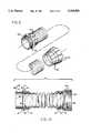
- FIG. 1is a perspective view of a pool cleaner having a flexible hose incorporating various aspects of the present invention, certain parts being removed for simplicity of illustration;
- FIG. 2is an enlarged side elevational view of the flexible hose of FIG. 1, partly broken away and shown in cross-section, with a flotation cuff attached;
- FIGS. 3A and 3Bare sectional views of the hose taken along the line 3--3 of FIG. 2 showing the method of attachment of the flotation cuff to the hose;
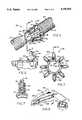
- FIG. 4is an enlarged fragmentary perspective view of a wheel cage attached to the hose according to the present invention.
- FIG. 5is an enlarged end view of the wheel cage taken along the line 5--5 of FIG. 4;
- FIG. 6is a fragmentary sectional view of the wheel cage taken along the line 6--6 of FIG. 5;
- FIG. 7is a further enlarged sectional view of a wheel mounted in the wheel cage taken along the line 7--7 of FIG. 6;
- FIG. 8is a fragmentary perspective view of a portion of the wheel cage of FIG. 4 showing the method of attaching the wheel to the wheel cage;
- FIG. 9is an exploded perspective view of the hose and end fittings of the present invention.
- FIG. 10is a side-elevational view of the hose and end fittings of FIG. 9, with the fittings shown in cross-section.
- the present inventionis embodied in a hose 20 and attachments 21, 22 and 23 that are incorporated in an illustrative pool cleaner 24 in a swimming pool 25.
- the pool cleaneris of the type having a surface unit 27 that is connected by an upper, floating section of the hose to an outlet 28 in the wall of the swimming pool to receive water under pressure from the filtration system of the pool, and a subsurface cleaning head 29 that is connected to the surface unit 27 by a lower, non-floating section of the hose.
- the pool cleaneris shown herein for purposes of illustration, and does not constitute a part of the invention.
- the hose 20is of flexible thin-walled tubular construction and has a plurality of elongated portions 30 which comprise a series of ribs 31 that alternate with grooves 32, forming most of the length of the hose.
- the ribbed portionsare joined together by relatively short smooth portions 33 of smaller outside diameter providing mounting areas for attachments such as flotation cuffs, shown at 21 on the floating section of the hose, wheel cages, shown at 22 on the lower section of the hose, and fittings, shown at 23 attaching the hose to the surface unit 27, outlet 28 and cleaning head 29.
- the hoseis made of a hard, durable plastic and so ribbed portions are necessary to provide flexibility and resilience to the hose.
- the cylindrical sectionsare not significantly resilient and do not contribute to the flexibility of the hose.
- the flotation cuffs, the wheel cages and the fittingshave generally cylindrical bodies.
- the flotation cuffs and wheel cageseach have longitudinal slots 34 and 35 to allow radial expansion of the hollow cylindrical bodies and insertion of a smooth portion of the hose into the bodies. When the expansion is relaxed, the cylindrical bodies contract into loosely-assembled relation with the smooth portion of the hose.
- the longitudinal slots in both the flotation cuff and the wheel cageare narrower than the diameter of the smooth portion of the hose and so the attached cuff and cage do not detach from the hose.
- a plurality of flotation cuffsare attached to the second portions along the length of the floating hose.
- the flotation cuffsare made of a buoyant material such as foamed polypropylene.
- the length of the flotation cuffs 21is about the same as, or slightly less than, the length of the smooth portions 33 of the hose 20.
- the longitudinal slot 34 along the length of the flotation cuffpermits radial expansion of the flotation cuff and insertion of a smooth portion of the hose into the hollow core of the flotation cuff. The longitudinal slot 34 is then released and contracts around the smooth portion of the hose.
- Each of the flotation cuffsis thereby attached to the hose to provide buoyancy to that portion of the hose.
- the hose 20 extending between the surface unit 27 and cleaning head 29sinks so that the cleaning head can move about the bottom of the swimming pool 25 and disrupt the settling of dirt and debris. Because the submerged hose is often dragged across the bottom of the pool, the smooth portions of the submerged hose are used to attach the wheel cages 22 to the hose. The wheel cages help reduce the friction between the hose and the pool bottom.
- the wheel cage 22has a hollow cylindrical body 37.
- the longitudinal slots 35permit radial expansion of the wheel cage and insertion of a smooth portion 33 of the hose into the body of the wheel cage.
- the length of each wheel cageis about the same as, or slightly less than, the length of the smooth portions of the hose.
- each wheel cagehas a first diameter on the forward end 38 and a second, slightly greater diameter on the other trailing end 39.
- a short step 40connects the forward end and the trailing end. The step and the greater diameter of the trailing end of the wheel cage cause a small circular gap 46 between the trailing end and the smooth portion of the hose. This gap provides space for a weight (not shown) for the hose.
- a plurality of radially outwardly directed fins 41are formed around the circumference of the body 37 of each wheel cage 21. Each fin perpendicularly extends from the cylindrical body along the longitudinal length of the wheel cage. The fins are arranged in pairs and each pair forms a slot 42 for mounting wheels 43 around the wheel cage.
- an axle 44 formed on one fin 41A of each pair of finsextends toward the second fin 41B in the pair.
- the finsare pried apart and the wheel mounted on the axle.
- the axlerotatably holds the wheel in the slot.
- Each wheel 43is disc-shaped with a central aperture 45 into which the axle 44 is inserted.
- the wheelsalso have an optional circular groove 47 extending around one side.
- a plurality of wheels 43are mounted around the circumference of each wheel cage 22.
- the submerged hose 20is dragged across the pool bottom by the cleaning head 29.
- the wheelscontact the bottom of the pool 25 and rotate, thereby reducing the friction between the hose and the pool bottom.
- each fin 41forms an incline relative to the cylindrical body 37 of the wheel cage 21 so that each fin has a greater height on the trailing end 39 of the wheel cage than on the forward end 38.
- the wheels 43are mounted on the trailing end of the fin. Should the pool bottom contact a fin as the cleaning head pulls the hose, the incline draws the pool bottom into contact with the associated wheel and lifts the hose and wheel cage above contact with the pool bottom, leaving only the wheel in contact with the pool bottom. The wheel then rotates to reduce the friction between the hose and pool bottom.
- the fittings 23may be used to attach the ends of the hoses 20 to the pump outlet 28, surface unit 27 or cleaning head apparatus 29.
- Each fittingincludes either a male or a female threadable engagement end 49 to attach the fitting to the desired apparatus.
- a plurality of grooves 50 around the circumference of the fittingassist the user in grasping and turning the fitting to engage the fitting to a threaded coupling such as the pump outlet in a wet, swimming pool environment.
- Each fitting 23can be rotatably and removeably attached to a ribbed portion of the hose 23. Specifically, to attach the hose to the fitting, the hose is cut so that a ribbed portion forms the end of the hose. Each fitting has an internal abutment 51 around the interior circumference of the fitting. The hose is attached to the fitting by collapsing the hose wall and inserting the end of the hose into the fitting so that the abutment is aligned with the groove 32 between two ribs 31 on the end of the hose as shown in FIG. 10. The hose wall is then expanded and the abutment and end rib engage to prevent detachment of the hose from the fitting under normal operating parameters. To detach the hose from the fitting when the hose is not in use, the wall of the hose is collapsed and the hose pulled out of the fitting.
- the fittingWhen in use, water pressure within the hose exerts pressure against the rib 31 and internal abutment 51 and thereby prevents the hose 20 from detaching from the fitting 23. When not in use, however, the fitting may rotate about the hose. Therefore, the fitting may be threaded, for instance, to the outlet 28 or without causing kinks in the hose.
- the pumpforces water through the hose 20.
- the water pressurecauses the fittings 23 tightly to grip the hose.
- the flotation cuffs 21cause the hose to float.
- the wheel cages 22 and the associated wheels 43 mounted thereinreduce the friction between the hose and the pool walls and hence the cleaning head 29 can cover more area with less expenditure of energy.
- the present inventionpermits inexpensive manufacturing and simple use of a flexible hose both in a floating environment and in an environment in which the hose moves across a rough surface.
- the hoseis easily and removeably connected to a fitting and yet when in use the fitting is securely attached the hose.
- Each of the various parts of the present inventioncan be inexpensively made of different plastics through the various techniques known in the art.
- Eachis also very durable and simple to use. Therefore, the novice pool owner can make effective use of the present invention.
Landscapes
- Engineering & Computer Science (AREA)
- General Engineering & Computer Science (AREA)
- Mechanical Engineering (AREA)
- Architecture (AREA)
- Civil Engineering (AREA)
- Structural Engineering (AREA)
- Rigid Pipes And Flexible Pipes (AREA)
Abstract
Description
Claims (11)
Priority Applications (1)
| Application Number | Priority Date | Filing Date | Title |
|---|---|---|---|
| US07/818,291US5195563A (en) | 1988-11-15 | 1992-01-09 | Flexible hose and fittings |
Applications Claiming Priority (2)
| Application Number | Priority Date | Filing Date | Title |
|---|---|---|---|
| US27153988A | 1988-11-15 | 1988-11-15 | |
| US07/818,291US5195563A (en) | 1988-11-15 | 1992-01-09 | Flexible hose and fittings |
Related Parent Applications (1)
| Application Number | Title | Priority Date | Filing Date |
|---|---|---|---|
| US27153988ADivision | 1988-11-15 | 1988-11-15 |
Publications (1)
| Publication Number | Publication Date |
|---|---|
| US5195563Atrue US5195563A (en) | 1993-03-23 |
Family
ID=26954983
Family Applications (1)
| Application Number | Title | Priority Date | Filing Date |
|---|---|---|---|
| US07/818,291Expired - LifetimeUS5195563A (en) | 1988-11-15 | 1992-01-09 | Flexible hose and fittings |
Country Status (1)
| Country | Link |
|---|---|
| US (1) | US5195563A (en) |
Cited By (28)
| Publication number | Priority date | Publication date | Assignee | Title |
|---|---|---|---|---|
| US6065499A (en)* | 1998-12-21 | 2000-05-23 | Eaton Corporation | Lateral stress relief mechanism for vacuum bellows |
| US6076560A (en)* | 1998-04-30 | 2000-06-20 | Corrupipe Cc | Pool cleaner hose weight |
| US6119707A (en)* | 1998-06-19 | 2000-09-19 | Jordan; Ginger | Octosquirt pool sweep cleaner |
| USD433545S (en)* | 1999-10-19 | 2000-11-07 | H-Tech, Inc. | Swimming pool cleaner housing |
| US6154915A (en)* | 1998-09-21 | 2000-12-05 | Wiseman, Jr.; Orville A. | Swimming pool aid |
| US6231054B1 (en) | 1998-12-21 | 2001-05-15 | Axcelis Technologies, Inc. | Elastomeric sliding seal for vacuum bellows |
| USD445225S1 (en) | 1999-10-19 | 2001-07-17 | H-Tech, Inc. | Pool cleaner |
| US6279961B1 (en) | 1999-11-16 | 2001-08-28 | Polaris Pools Systems, Inc. | Rotatable hose coupling |
| US20050113622A1 (en)* | 2003-10-10 | 2005-05-26 | Eit Drent | Catalytic trimerization of olefinic monomers |
| WO2008001087A3 (en)* | 2006-06-30 | 2008-05-02 | Technip France Sa | Method and apparatus for mounting distributed buoyancy modules on a rigid pipeline |
| USD581607S1 (en)* | 2007-09-25 | 2008-11-25 | Zodiac Pool Care, Inc. | Pool cleaner |
| US20090007349A1 (en)* | 2004-08-30 | 2009-01-08 | Bauckman Mark J | Automatic swimming pool cleaners and associated hoses |
| US20090026324A1 (en)* | 2007-07-23 | 2009-01-29 | Hensley Calvin G | Block liner |
| US20090077759A1 (en)* | 2007-09-25 | 2009-03-26 | Van Der Meijden Hendrikus Johannes | Pool Cleaner Hoses and Methods for Making the Same |
| US20090295148A1 (en)* | 2004-11-17 | 2009-12-03 | Wayne Benjamin Balie | Connector for an automatic pool cleaner |
| US20100269943A1 (en)* | 2008-05-22 | 2010-10-28 | Akio Arai | Duct structure of a hollow wall using a through-pass duct member |
| USD634406S1 (en)* | 2010-01-28 | 2011-03-15 | Zokiac Pool Systems, Inc. | Hose cuff |
| USD641467S1 (en)* | 2009-09-14 | 2011-07-12 | Home Health Medical Equipment Incorporated | Hose cuff |
| JP2014167250A (en)* | 2008-12-24 | 2014-09-11 | Crystal Lagoons (Curacao) Bv | Efficient filtration process for water in tank for use in recreational facilities and ornamental use, said filtration performed over small volume of water and not on totality of water in tank |
| US9810357B2 (en) | 2015-04-24 | 2017-11-07 | Teknor Apex Company | Lightweight, high flow hose assembly and method of manufacture |
| US9815254B2 (en) | 2015-04-24 | 2017-11-14 | Teknor Apex Company | Lightweight, high flow hose assembly and method of manufacture |
| USD812202S1 (en)* | 2015-10-29 | 2018-03-06 | Teknor Apex Company | Radially expandable hose assembly including fittings |
| US10000035B2 (en) | 2015-04-24 | 2018-06-19 | Teknor Apex Company | Lightweight, high flow hose assembly and method of manufacture |
| US10132435B2 (en) | 2015-04-24 | 2018-11-20 | Teknor Apex Company | Lightweight, high flow hose assembly and method of manufacture |
| US10161116B2 (en) | 2016-09-21 | 2018-12-25 | Kohler Co. | Kitchen faucet pulldown weight |
| US10458576B2 (en) | 2016-10-13 | 2019-10-29 | Teknor Apex Company | Hose assembly with modified thermoplastic inner tube |
| US10458574B2 (en) | 2015-04-24 | 2019-10-29 | Teknor Apex Company | Lightweight, high flow hose assembly and method of manufacture |
| US20230383873A1 (en)* | 2018-10-12 | 2023-11-30 | Crushproof Tubing Company | Flexible drain pipe |
Citations (9)
| Publication number | Priority date | Publication date | Assignee | Title |
|---|---|---|---|---|
| US2650113A (en)* | 1948-06-05 | 1953-08-25 | Hoover Co | Filter adapter |
| US3332093A (en)* | 1965-05-25 | 1967-07-25 | Hewitt Robins Inc | Float for submarine hose system |
| US3727949A (en)* | 1971-12-20 | 1973-04-17 | Dayco Corp | Hose construction |
| US3838713A (en)* | 1972-10-10 | 1974-10-01 | Tu Co Inc | Trailer tube and connection |
| US4558889A (en)* | 1984-10-26 | 1985-12-17 | Action Technology | Aquatic vacuum hose swivel cuff |
| US4651377A (en)* | 1985-12-23 | 1987-03-24 | Staples Samuel C | Brush attachment for automated pool sweepers |
| US4839063A (en)* | 1984-03-12 | 1989-06-13 | Spooner Est | Cleaning of a body of liquid |
| US4909547A (en)* | 1988-05-26 | 1990-03-20 | Chardon Rubber Company | Coupler arrangement |
| US5042844A (en)* | 1988-12-29 | 1991-08-27 | Hitachi, Ltd. | Hose fixture device |
- 1992
- 1992-01-09USUS07/818,291patent/US5195563A/ennot_activeExpired - Lifetime
Patent Citations (9)
| Publication number | Priority date | Publication date | Assignee | Title |
|---|---|---|---|---|
| US2650113A (en)* | 1948-06-05 | 1953-08-25 | Hoover Co | Filter adapter |
| US3332093A (en)* | 1965-05-25 | 1967-07-25 | Hewitt Robins Inc | Float for submarine hose system |
| US3727949A (en)* | 1971-12-20 | 1973-04-17 | Dayco Corp | Hose construction |
| US3838713A (en)* | 1972-10-10 | 1974-10-01 | Tu Co Inc | Trailer tube and connection |
| US4839063A (en)* | 1984-03-12 | 1989-06-13 | Spooner Est | Cleaning of a body of liquid |
| US4558889A (en)* | 1984-10-26 | 1985-12-17 | Action Technology | Aquatic vacuum hose swivel cuff |
| US4651377A (en)* | 1985-12-23 | 1987-03-24 | Staples Samuel C | Brush attachment for automated pool sweepers |
| US4909547A (en)* | 1988-05-26 | 1990-03-20 | Chardon Rubber Company | Coupler arrangement |
| US5042844A (en)* | 1988-12-29 | 1991-08-27 | Hitachi, Ltd. | Hose fixture device |
Cited By (37)
| Publication number | Priority date | Publication date | Assignee | Title |
|---|---|---|---|---|
| US6076560A (en)* | 1998-04-30 | 2000-06-20 | Corrupipe Cc | Pool cleaner hose weight |
| US6119707A (en)* | 1998-06-19 | 2000-09-19 | Jordan; Ginger | Octosquirt pool sweep cleaner |
| US6154915A (en)* | 1998-09-21 | 2000-12-05 | Wiseman, Jr.; Orville A. | Swimming pool aid |
| US6231054B1 (en) | 1998-12-21 | 2001-05-15 | Axcelis Technologies, Inc. | Elastomeric sliding seal for vacuum bellows |
| US6065499A (en)* | 1998-12-21 | 2000-05-23 | Eaton Corporation | Lateral stress relief mechanism for vacuum bellows |
| USD445225S1 (en) | 1999-10-19 | 2001-07-17 | H-Tech, Inc. | Pool cleaner |
| USD433545S (en)* | 1999-10-19 | 2000-11-07 | H-Tech, Inc. | Swimming pool cleaner housing |
| US6279961B1 (en) | 1999-11-16 | 2001-08-28 | Polaris Pools Systems, Inc. | Rotatable hose coupling |
| US20050113622A1 (en)* | 2003-10-10 | 2005-05-26 | Eit Drent | Catalytic trimerization of olefinic monomers |
| US7273959B2 (en) | 2003-10-10 | 2007-09-25 | Shell Oil Company | Catalytic trimerization of olefinic monomers |
| US8590088B2 (en) | 2004-08-30 | 2013-11-26 | Zodiac Pool Care Europe | Automatic swimming pool cleaners and associated hoses |
| US8590089B2 (en) | 2004-08-30 | 2013-11-26 | Zodiac Pool Care Europe | Automatic swimming pool cleaners and associated hoses |
| US20090007349A1 (en)* | 2004-08-30 | 2009-01-08 | Bauckman Mark J | Automatic swimming pool cleaners and associated hoses |
| US20090295148A1 (en)* | 2004-11-17 | 2009-12-03 | Wayne Benjamin Balie | Connector for an automatic pool cleaner |
| WO2008001087A3 (en)* | 2006-06-30 | 2008-05-02 | Technip France Sa | Method and apparatus for mounting distributed buoyancy modules on a rigid pipeline |
| US20090313794A1 (en)* | 2006-06-30 | 2009-12-24 | Sylvain Denniel | Method and apparatus for mounting distributed buoyancy modules on a rigid pipeline |
| GB2439829B (en)* | 2006-06-30 | 2011-03-09 | Technip France | Apparatus for mounting distribute buoyancy modules on a rigid pipeline |
| US8573888B2 (en) | 2006-06-30 | 2013-11-05 | Technip France Sa | Method and apparatus for mounting distributed buoyancy modules on a rigid pipeline |
| US20090026324A1 (en)* | 2007-07-23 | 2009-01-29 | Hensley Calvin G | Block liner |
| WO2009042348A1 (en)* | 2007-09-25 | 2009-04-02 | Zodiac Pool Care, Inc. | Pool cleaner hoses and methods for making the same |
| US20090077759A1 (en)* | 2007-09-25 | 2009-03-26 | Van Der Meijden Hendrikus Johannes | Pool Cleaner Hoses and Methods for Making the Same |
| USD581607S1 (en)* | 2007-09-25 | 2008-11-25 | Zodiac Pool Care, Inc. | Pool cleaner |
| US20100269943A1 (en)* | 2008-05-22 | 2010-10-28 | Akio Arai | Duct structure of a hollow wall using a through-pass duct member |
| JP2014167250A (en)* | 2008-12-24 | 2014-09-11 | Crystal Lagoons (Curacao) Bv | Efficient filtration process for water in tank for use in recreational facilities and ornamental use, said filtration performed over small volume of water and not on totality of water in tank |
| USD641467S1 (en)* | 2009-09-14 | 2011-07-12 | Home Health Medical Equipment Incorporated | Hose cuff |
| USD634406S1 (en)* | 2010-01-28 | 2011-03-15 | Zokiac Pool Systems, Inc. | Hose cuff |
| US10000035B2 (en) | 2015-04-24 | 2018-06-19 | Teknor Apex Company | Lightweight, high flow hose assembly and method of manufacture |
| US9815254B2 (en) | 2015-04-24 | 2017-11-14 | Teknor Apex Company | Lightweight, high flow hose assembly and method of manufacture |
| US9810357B2 (en) | 2015-04-24 | 2017-11-07 | Teknor Apex Company | Lightweight, high flow hose assembly and method of manufacture |
| US10132435B2 (en) | 2015-04-24 | 2018-11-20 | Teknor Apex Company | Lightweight, high flow hose assembly and method of manufacture |
| US10344899B2 (en) | 2015-04-24 | 2019-07-09 | Teknor Apex Company | Lightweight, high flow hose assembly and method of manufacture |
| US10458574B2 (en) | 2015-04-24 | 2019-10-29 | Teknor Apex Company | Lightweight, high flow hose assembly and method of manufacture |
| USD812202S1 (en)* | 2015-10-29 | 2018-03-06 | Teknor Apex Company | Radially expandable hose assembly including fittings |
| US10161116B2 (en) | 2016-09-21 | 2018-12-25 | Kohler Co. | Kitchen faucet pulldown weight |
| US10458576B2 (en) | 2016-10-13 | 2019-10-29 | Teknor Apex Company | Hose assembly with modified thermoplastic inner tube |
| US20230383873A1 (en)* | 2018-10-12 | 2023-11-30 | Crushproof Tubing Company | Flexible drain pipe |
| US12110990B2 (en)* | 2018-10-12 | 2024-10-08 | Crushproof Tubing Company | Flexible drain pipe |
Similar Documents
| Publication | Publication Date | Title |
|---|---|---|
| US5195563A (en) | Flexible hose and fittings | |
| EP0633371B1 (en) | Swimming pool cleaner operating head | |
| US6733046B1 (en) | Hose swivel connection apparatus | |
| US5105848A (en) | Automatic relief valve | |
| US4193156A (en) | Apparatus for cleaning submerged surfaces | |
| CA1283935C (en) | Flexible pipe coupler | |
| AU732645B2 (en) | Filter bag for a pool cleaner | |
| US5740576A (en) | Device for dislodging a submersible swimming pool cleaner | |
| CA2621432C (en) | Automatic swimming pool cleaners | |
| AU2003284226B2 (en) | Automatic pool cleaner power conduit including stiff sections | |
| US4221662A (en) | Pool skimming device | |
| EP0528829B1 (en) | Swimming pool cover and roll-up device | |
| US6279961B1 (en) | Rotatable hose coupling | |
| AU2006331629A1 (en) | Automatic pool cleaner power conduit including stiff sections and resilient axially flexible couplers | |
| US6049933A (en) | Bumper assemblies for swimming pool cleaners | |
| US6725489B1 (en) | Automatic pool cleaner accessory | |
| US4393526A (en) | Pool cleaning apparatus | |
| AU701368B2 (en) | Cleaning of submerged surfaces | |
| US11008771B2 (en) | In-water suction cleaner | |
| US4982754A (en) | Pool cleaner accessory | |
| US4753256A (en) | Pool cleaner hose | |
| GB2153209A (en) | Accessory for swimming pool cleaner | |
| WO1999022100A1 (en) | Submersible pool cleaner steering device and method | |
| US20050155647A1 (en) | Pool cleaner deployment arrangement | |
| AU2008202422B2 (en) | Automatic pool cleaner power conduit including stiff sections |
Legal Events
| Date | Code | Title | Description |
|---|---|---|---|
| AS | Assignment | Owner name:OAKLEIGH LIMITED, CHANNEL ISLANDS Free format text:ASSIGNMENT OF ASSIGNORS INTEREST.;ASSIGNOR:BROOKS, DAVID A.;REEL/FRAME:005998/0629 Effective date:19911213 | |
| STCF | Information on status: patent grant | Free format text:PATENTED CASE | |
| AS | Assignment | Owner name:GARMAR, INC., CALIFORNIA Free format text:ASSIGNMENT OF ASSIGNORS INTEREST.;ASSIGNOR:OAKLEIGH LIMITED;REEL/FRAME:006460/0482 Effective date:19930125 | |
| FEPP | Fee payment procedure | Free format text:ENTITY STATUS SET TO SMALL (ORIGINAL EVENT CODE: SMAL); ENTITY STATUS OF PATENT OWNER: SMALL ENTITY | |
| FPAY | Fee payment | Year of fee payment:4 | |
| FPAY | Fee payment | Year of fee payment:8 | |
| FPAY | Fee payment | Year of fee payment:12 | |
| AS | Assignment | Owner name:ING BANK N.V., UNITED KINGDOM Free format text:SECURITY AGREEMENT;ASSIGNOR:ZODIAC POOL CARE, INC.;REEL/FRAME:019910/0327 Effective date:20070927 Owner name:ING BANK N.V.,UNITED KINGDOM Free format text:SECURITY AGREEMENT;ASSIGNOR:ZODIAC POOL CARE, INC.;REEL/FRAME:019910/0327 Effective date:20070927 | |
| AS | Assignment | Owner name:ZODIAC POOL SYSTEMS, INC., CALIFORNIA Free format text:RELEASE BY SECURED PARTY;ASSIGNOR:ING BANK N.V., LONDON BRANCH;REEL/FRAME:041318/0263 Effective date:20161220 |