US5194723A - Photoacoustic control of a pulsed light material removal process - Google Patents
Photoacoustic control of a pulsed light material removal processDownload PDFInfo
- Publication number
- US5194723A US5194723AUS07/813,866US81386691AUS5194723AUS 5194723 AUS5194723 AUS 5194723AUS 81386691 AUS81386691 AUS 81386691AUS 5194723 AUS5194723 AUS 5194723A
- Authority
- US
- United States
- Prior art keywords
- pressure wave
- photoacoustic
- wave signals
- scan speed
- photoacoustic pressure
- Prior art date
- Legal status (The legal status is an assumption and is not a legal conclusion. Google has not performed a legal analysis and makes no representation as to the accuracy of the status listed.)
- Expired - Fee Related
Links
- 239000000463materialSubstances0.000titleclaimsabstractdescription85
- 238000000034methodMethods0.000titleclaimsabstractdescription60
- 230000008569processEffects0.000titleabstractdescription19
- 239000000758substrateSubstances0.000claimsabstractdescription31
- 230000001678irradiating effectEffects0.000claimsabstractdescription10
- 239000002245particleSubstances0.000claimsdescription20
- CURLTUGMZLYLDI-UHFFFAOYSA-NCarbon dioxideChemical compoundO=C=OCURLTUGMZLYLDI-UHFFFAOYSA-N0.000claimsdescription16
- XLYOFNOQVPJJNP-UHFFFAOYSA-NwaterSubstancesOXLYOFNOQVPJJNP-UHFFFAOYSA-N0.000claimsdescription16
- 230000003287optical effectEffects0.000claimsdescription10
- 239000008188pelletSubstances0.000claimsdescription10
- 230000003750conditioning effectEffects0.000claimsdescription9
- VYPSYNLAJGMNEJ-UHFFFAOYSA-Nsilicon dioxideInorganic materialsO=[Si]=OVYPSYNLAJGMNEJ-UHFFFAOYSA-N0.000claimsdescription9
- 229910002092carbon dioxideInorganic materials0.000claimsdescription8
- 239000001569carbon dioxideSubstances0.000claimsdescription8
- 230000003247decreasing effectEffects0.000claimsdescription6
- 239000010453quartzSubstances0.000claimsdescription6
- 230000004044responseEffects0.000claimsdescription4
- 238000001816coolingMethods0.000claims7
- 238000004140cleaningMethods0.000claims3
- 239000003973paintSubstances0.000description49
- 238000012360testing methodMethods0.000description18
- 229910052782aluminiumInorganic materials0.000description17
- XAGFODPZIPBFFR-UHFFFAOYSA-NaluminiumChemical compound[Al]XAGFODPZIPBFFR-UHFFFAOYSA-N0.000description17
- 238000004867photoacoustic spectroscopyMethods0.000description17
- 238000000576coating methodMethods0.000description16
- 230000006870functionEffects0.000description9
- 230000008901benefitEffects0.000description8
- 238000002679ablationMethods0.000description7
- 239000011343solid materialSubstances0.000description6
- 239000004020conductorSubstances0.000description5
- 229910052751metalInorganic materials0.000description5
- 239000002184metalSubstances0.000description5
- 150000001875compoundsChemical class0.000description4
- 239000000428dustSubstances0.000description4
- 239000007787solidSubstances0.000description4
- 229910052724xenonInorganic materials0.000description4
- FHNFHKCVQCLJFQ-UHFFFAOYSA-Nxenon atomChemical compound[Xe]FHNFHKCVQCLJFQ-UHFFFAOYSA-N0.000description4
- 239000004593EpoxySubstances0.000description3
- 239000011248coating agentSubstances0.000description3
- 230000006835compressionEffects0.000description3
- 238000007906compressionMethods0.000description3
- 230000007613environmental effectEffects0.000description3
- 230000035939shockEffects0.000description3
- 230000036962time dependentEffects0.000description3
- 231100000331toxicToxicity0.000description3
- 230000002588toxic effectEffects0.000description3
- UQSXHKLRYXJYBZ-UHFFFAOYSA-NIron oxideChemical compound[Fe]=OUQSXHKLRYXJYBZ-UHFFFAOYSA-N0.000description2
- 229910000831SteelInorganic materials0.000description2
- 238000010521absorption reactionMethods0.000description2
- 239000003570airSubstances0.000description2
- 238000004458analytical methodMethods0.000description2
- 239000002131composite materialSubstances0.000description2
- 230000007797corrosionEffects0.000description2
- 238000005260corrosionMethods0.000description2
- 239000008367deionised waterSubstances0.000description2
- 229910021641deionized waterInorganic materials0.000description2
- 238000010586diagramMethods0.000description2
- 238000005553drillingMethods0.000description2
- 239000005350fused silica glassSubstances0.000description2
- 239000004814polyurethaneSubstances0.000description2
- 229920002635polyurethanePolymers0.000description2
- 238000012545processingMethods0.000description2
- 239000010959steelSubstances0.000description2
- -1BB'sSubstances0.000description1
- 229920002472StarchPolymers0.000description1
- 241000209140TriticumSpecies0.000description1
- 235000021307TriticumNutrition0.000description1
- 239000012080ambient airSubstances0.000description1
- 239000003990capacitorSubstances0.000description1
- 230000015556catabolic processEffects0.000description1
- 230000008859changeEffects0.000description1
- 238000002485combustion reactionMethods0.000description1
- 238000004891communicationMethods0.000description1
- 238000009833condensationMethods0.000description1
- 230000005494condensationEffects0.000description1
- 238000013016dampingMethods0.000description1
- 238000000354decomposition reactionMethods0.000description1
- 230000003292diminished effectEffects0.000description1
- 230000000694effectsEffects0.000description1
- 238000005516engineering processMethods0.000description1
- 230000001747exhibiting effectEffects0.000description1
- 238000002474experimental methodMethods0.000description1
- 239000012530fluidSubstances0.000description1
- 230000004907fluxEffects0.000description1
- 230000036541healthEffects0.000description1
- 230000036039immunityEffects0.000description1
- 230000003116impacting effectEffects0.000description1
- 238000009413insulationMethods0.000description1
- JEIPFZHSYJVQDO-UHFFFAOYSA-Niron(III) oxideInorganic materialsO=[Fe]O[Fe]=OJEIPFZHSYJVQDO-UHFFFAOYSA-N0.000description1
- 239000007788liquidSubstances0.000description1
- 238000011068loading methodMethods0.000description1
- 238000012423maintenanceMethods0.000description1
- 238000013017mechanical dampingMethods0.000description1
- 150000002894organic compoundsChemical class0.000description1
- 230000003534oscillatory effectEffects0.000description1
- 230000003647oxidationEffects0.000description1
- 238000007254oxidation reactionMethods0.000description1
- 230000000149penetrating effectEffects0.000description1
- 238000010895photoacoustic effectMethods0.000description1
- 230000000750progressive effectEffects0.000description1
- 238000009419refurbishmentMethods0.000description1
- 230000002441reversible effectEffects0.000description1
- 238000012552reviewMethods0.000description1
- 239000004576sandSubstances0.000description1
- 230000003595spectral effectEffects0.000description1
- 238000001228spectrumMethods0.000description1
- 235000019698starchNutrition0.000description1
- 239000008107starchSubstances0.000description1
- 239000010891toxic wasteSubstances0.000description1
- 238000009834vaporizationMethods0.000description1
- 230000008016vaporizationEffects0.000description1
- 230000000007visual effectEffects0.000description1
- 239000002699waste materialSubstances0.000description1
Images


Classifications
- G—PHYSICS
- G01—MEASURING; TESTING
- G01N—INVESTIGATING OR ANALYSING MATERIALS BY DETERMINING THEIR CHEMICAL OR PHYSICAL PROPERTIES
- G01N29/00—Investigating or analysing materials by the use of ultrasonic, sonic or infrasonic waves; Visualisation of the interior of objects by transmitting ultrasonic or sonic waves through the object
- G01N29/22—Details, e.g. general constructional or apparatus details
- G01N29/24—Probes
- G01N29/2418—Probes using optoacoustic interaction with the material, e.g. laser radiation, photoacoustics
- G—PHYSICS
- G01—MEASURING; TESTING
- G01N—INVESTIGATING OR ANALYSING MATERIALS BY DETERMINING THEIR CHEMICAL OR PHYSICAL PROPERTIES
- G01N2291/00—Indexing codes associated with group G01N29/00
- G01N2291/04—Wave modes and trajectories
- G01N2291/042—Wave modes
- G01N2291/0423—Surface waves, e.g. Rayleigh waves, Love waves
Definitions
- the present inventionrelates to a material removal system, and more particularly, to a system that directs pulsed light (radiant energy) at a material to be removed from a substrate and uses the resulting photoacoustic effect to control the amount of material removed.
- pulsed lightradiant energy
- Coatingsare pervasive in our energy-intensive, consumption-oriented society. Coatings provide: immunity to corrosion, thermal insulation, shielding, as well as appearance enhancement, and an aid in identification.
- PMBparticle medium blast
- Toxic wasterequires special handling in order to dispose of it in a manner which minimizes damage to the environment.
- Another problem with PMBis that it generates a lot of dust which obscures the area being stripped. This impairs visual feedback necessary to control the process, resulting in damaged surfaces.
- Some airlineshave used water jets to remove paint from aircraft.
- friction caused as a water jetimpacts a surface such as aluminum generates heat which can damage the aluminum, especially if it is thin, like that found on aircraft.
- Another problem with this methodis that the high pressure water can penetrate into the internal regions of the aircraft which are susceptible to water damage.
- Radiant energy paint removal techniquesare also known in the art.
- One such systemuses a laser and video frame grabber in a video controlled paint removal system in which paint is stripped from a surface using particle medium blast methods of the type discussed above while a video camera converts images of the surface being stripped into electronic data signals. The data signals are used to control the particle blast.
- a processorcompares the data signals with parameters stored in a memory to determine whether sufficient paint has been removed from the surface being stripped. If an insufficient amount of paint has been removed, then the surface continues being irradiated. If the optically irradiated area has been adequately stripped, the processor directs the particles to strip another area.
- a significant problem with the video controlled paint removal systemis that the amount of data which is generated and which must be processed is enormous. Hence, real time control of video controlled paint removal systems is extremely difficult.
- Another problem with a video controlled paint removal systemis that large amounts of dust are generated from the effect of the particle blast impacting the surface being stripped. The dust can impair the scene being observed by the video camera, also making real time control of the process difficult.
- PASphotoacoustic spectroscopy
- the heat flowcauses oscillatory time dependent pressure in a small volume of gas at the solid-gas interface.
- An additional source of time dependent pressure in the gascan arise when the absorbing solid ablates and subsequently burns to release its heat of combustion. It is this motion of the gas which produces the acoustic signal that is characteristic of the solid, also referred to as the photoacoustic characteristic of the solid.
- ⁇is the heat capacity ratio for the ambient air
- ⁇is a constant
- ( ⁇1.03 for air)
- Eis the energy absorbed by the surface of the material being irradiated
- Ris the distance of the pressure wave from the surface.
- the circuit boardis mounted to an X-Y moving table under the direction of the control system which positions selected hole sites on the circuit board under the laser beam.
- the system described in the '727 patentis not suitable for removing selected layers of material from large surfaces in predetermined patterns.
- the system described in the '727 patentmodulates the output of the light source as a function of the amplitude of the photoacoustic signals. Such modulation disadvantageously shortens the useful life of the laser.
- a needalso exists for a coating removal system and method that can be controlled to avoid subjecting a surface which is to be exposed to an excessive amount of energy which would damage delicate structures.
- a further needexists for a coating removal systems which can be automated.
- a needexists for a system and method which promotes a long service life of the light source.
- the present inventionprovides an automated system and method for removing material which includes (1) irradiating a structure comprising at least one layer of material formed on a substrate with a light beam having an intensity sufficient to ablate the materials in order to expose selected regions of the substrate, where the ablated material generates photoacoustic pressure wave signals; (2) scanning the structure with the light beam along a predetermined path at a scan speed; (3) detecting the photoacoustic pressure wave; (4) determining an updated scan speed functionally related to the detected photoacoustic pressure wave signals; and (5) directing the scan speed to be equal to the updated scan speed.
- Another embodiment of the present inventionexposes a selected layer of a multilayered structure in a process which includes (1) irradiating the surface of multilayered structure at a first location with a light beam having sufficient intensity to ablate the irradiated layer; (2) detecting photoacoustic pressure wave signals generated at the irradiated surface; (3) comparing representations of the photoacoustic pressure wave signals with a reference value corresponding to a photoacoustic pressure wave signal of a layer of the structure selected to be exposed; and (4) directing the light source to irradiate a second selected location on the structure if the result of step (3) indicates the photoacoustic pressure wave signals are within a predetermined limit of the reference value.
- An advantage of the present inventionis that it provides an automated system for removing coatings from a substrate. Another advantage of the invention is that it is able to remove layers of coatings without damaging the layer to be exposed. A further advantage is that the invention may be employed to expose a selected layer of a multilayered structure. The invention also overcomes noise, environmental, and material handling problems associated with prior art material removing systems. A still further advantage is that the invention may be employed to remove coatings having varying, non-uniform thicknesses.
- FIG. 1is a block diagram of an example of an embodiment of the present invention which selectively removes one or more material layers from a structure so as to expose a desired surface.
- FIG. 2is a graph illustrating the functional relation between the pulse amplitude of the signal produced by the acoustic transducer and the speed of the robotic positioner.
- FIG. 3Ais a front, cross-sectional, elevation view of a flashlamp mounted in a housing.
- FIG. 3Bis a side, cross-sectional, elevation view of the flashlamp mounted in the housing.
- FIG. 4Ais a block diagram showing the signal conditioning circuit in greater detail than presented in FIG. 1.
- FIG. 4Bshows a graph of the output of line power unit 60 as a function of time.
- FIG. 4Cshows a graph of the output of track-and-hold circuit 62 as a function of time.
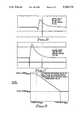
- FIG. 5illustrates the photoacoustic signature of yellow primer being ablated from an aluminum substrate by a KrF excimer laser.
- FIG. 6illustrates the photoacoustic pressure wave signal resulting from white paint being ablated from an aluminum surface.
- FIG. 7illustrates the photoacoustic pressure wave signal resulting from black paint being ablated from an aluminum surface.
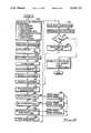
- FIG. 8is a flowchart representing the process of an example of one embodiment of the present invention.
- FIG. 9shows a graph illustrating the functional relation between the scan speed and the difference between the photoacoustic pressure wave signals and a reference signal.
- the present inventionprovides an automated system and method for exposing a selected surface of a layer of material of a multilayered structure formed of two or more layers of material, as for example, two layers of paint formed on an aluminum plate.
- the operation of the inventionrelies upon the phenomenon that different types of materials generate photoacoustic pressure wave signals when they ablate, and that these signals may be distinguished and used to control the process.
- Ablationis the rapid decomposition and vaporization of a material resulting from the absorption of energy by the material and is associated with the generation of pressure waves radiating from the surface of the material.
- the intensity of the pressure wavesis characteristic of the ablating material.
- An example of a system and method that uses photoacoustic feedback to control a material removal process embodying various features of the present inventiondirects an intense light beam to irradiate the surface of a layer of material of a multilayered structure which may be formed one or more layers of material formed on substrate.
- the intensity of the lightis sufficient to cause the irradiated surface to absorb enough light energy in the form of heat so that the material comprising the layer ablates.
- Thisgenerates a photoacoustic pressure wave signals characteristic of the amount of material.
- additional material from the successive layersablate.
- By detecting and discriminating the photoacoustic pressure wave signalsit can be determined when a particular layer of the substrate has been exposed.
- the lightis then directed to irradiate another region of the structure, thereby preventing damage to the substrate from excessive heat absorption.
- the photoacoustic pressure wavecan be used to control a material removal process.
- the present inventionis particularly well suited for removing layers of paint and epoxy from metallic surfaces. This is because the photoacoustic pressure wave signal characteristic of bare metal is virtually non-existent.
- the inventionmay also be used to strip corrosion from metal substrates.
- One principal advantage of the inventionis that selected layers of a structure can be exposed without regard to the thickness of any of the layers.
- FIG. 1A general overview of the present invention is described with reference to FIG. 1 where there is shown pulsed light source 10 controlled by light control o circuit 11.
- Light source 10generates light beam 12 which is emitted through window 13 so that it irradiates a selected region of multilayered structure 14.
- structure 14is described herein as having layers 16 and 18 formed on substrate 20, where in this example, it is desired to expose substrate 20.
- structure 14may be comprised of any number of layers formed on a substrate to be exposed.
- Light source 10provides the energy used to remove layers 16 and 18 through a process known as ablation. In typical applications of the invention, layers such as 16 and 18 are comprised of organic compounds.
- An important feature of the inventionis that it limits the amount of light exposure to which substrate 20 is subjected so that it is not damaged from absorbing too much energy. Damage caused by heat includes changes in the desired mechanical properties of the material, as for example, the modulus of elasticity, tensile strength, and/or shear strength. Heat damage could also cause the material to become distorted from its intended shape.
- Layer 16is ablated upon exposure to pulsed light beam 12, causing photoacoustic pressure wave signals 22 to be generated from irradiated surface 17. Pressure wave signals 22 which are detected by fast pressure transducer 24. After removal of layer 16 in the area of where light beam 12 impinges structure 14, continued irradiation results in ablation of layer 18, accompanied by generation of its own photoacoustic pressure wave signals.
- a computer controlled robotic positioning systemcomprising robotic positioner 28 to which light source 10 is mounted, and robotic controller 29, is employed to move the light source along a predetermined path.
- Robotic positioner 28is controlled by robotic controller 29 in accordance with instructions provided by data processor 30.
- Fast pressure transducer 24, also mounted to robotic positioner 28,is positioned to detect photoacoustic pressure wave signals 22 generated from structure 14.
- data processor 30may be an IBM AT compatible personal computer, although the scope of the invention includes the use of data processors other than that specifically identified above.
- Robot positioner 28may be a CIMROC 4000 Robot Controller manufactured by CIMCORP Precision Systems, Inc., Shoreview, Minn., although other commercially available industrial robots may also be employed in the implementation of the present invention. Techniques for controlling robotic positioner 28 so that it travels a predetermined path are well known by those of ordinary skill in the robotic field of technology.
- Transducer 24transforms photoacoustic pressure wave signals 22 into an analogous series of electrical pulses having pulse amplitudes corresponding to the intensity of the photoacoustic pressure wave signals 22.
- Transducer 24may be realized using a PCP Piezotronics Model 106B50 piezoelectric sensor.
- Signal conditioner 26receives the pulsed output signal of pressure transducer 24 and transforms it into a DC analog electrical output signal having a DC value proportional to the peak pulse amplitude of the signal received by signal conditioner 26.
- the output signal of signal conditioner 26is received by data processor 30 as a variable control input signal.
- processor 30Based on the value of the control input signal, processor 30, using an appropriate processing routine, calculates (or otherwise determines) an appropriate robotic speed value between minimum and maximum values for the scan speed of robotic positioner 28, as described below. Data processor 30 then generates a speed control output signal to robot controller 29 that corresponds to the determined robotic scan speed value. Robotic controller 29 then directs robotic positioner 28 to travel at a speed corresponding to the speed control output signal.
- the output signal from signal conditioner 26may be used as an address in a look-up table stored or generated by data processor 30 using appropriate processing software. Such software may retrieve a robotic speed value stored in particular address where the stored robotic speed value corresponds to a speed between minimum and maximum values. Data processor 30 then provides a scan speed control output signal based on that value to robot controller 28.
- the speed value determined by processor 30may be related to the peak pulse amplitude of the output signal of pressure transducer 24 by a decreasing function, as for example, linear with a negative slope, as shown in FIG. 2. Such function may be bounded within upper and lower speed limits. Examples of the relation between the speed value and the peak pulse amplitude are described below. In FIG. 2, if the peak pulse amplitude of the output signal 24a of pressure transducer 24 is equal to or less than a minimum average peak pulse threshold value, Threshold min , then the speed value is determined to be a maximum scan speed value, Scan Speed max .
- the speed valueis determined to be the minimum scan speed, Scan Speed min . If the peak pulse amplitude of the output signal 24a is equal to some amplitude P 2 , then the speed value is determined to be S 2 , where Threshold Min ⁇ P 2 ⁇ Threshold Max and ScanSpeed Max >S 2 ScanSpeed Min .
- Threshold Min⁇ P 2 ⁇ Threshold Max and ScanSpeed Max >S 2 ScanSpeed Min .
- Threshold min and Threshold maxmay be determined empirically as described below.
- a number of test scansare made using a light source such as light source 10 to irradiate a fresh sample structure representative of the structure that is to be processed by the method and system of the present invention.
- the operating parameters of the light sourcesuch as modulation frequency and duty cycle may be varied for each test.
- the distance between the light source and the test samplereferred to as the standoff distance, may be varied.
- a typical standoff distanceis 1.0 inch.
- the photoacoustic pressure wave signals generated at the ablating surfaces of the test samplesare detected by a pressure transducer such as pressure transducer 24 and recorded using suitable recording means.
- photographs of an oscilloscope screen of an oscilloscope, or equivalent device, connected to receive and display the output signals from the pressure detectormay be taken.
- An individualhereafter, "operator”
- the operatoridentifies the test sample having the most material removed, but still having an acceptable surface finish.
- the minimum threshold value, Threshold minis obtained by approximating the average value of the peak amplitudes of the photoacoustic pressure wave signals associated with that test sample.
- the operatormay also identify the test sample having the least amount of material removed, but still having an acceptable surface finish.
- the maximum threshold value, Threshold maxis obtained by approximating the average value of the amplitudes of the photoacoustic pressure wave signals associated with this latter test sample.
- Another way to determine the minimum and maximum threshold valuesis to perform the steps described in the preceding paragraph, but to also scan the test sample at different speeds while the test sample is being irradiated. Then, the test sample having the least amount of material removed, but still having an acceptable finish is identified.
- the maximum threshold valueis obtained from the amplitude of the photoacoustic pressure wave signals generated from the surface of that test sample in accordance with the methods described in the preceding paragraph.
- the scan rate at which this test sample was runthen becomes the minimum scan speed, Scan Speed min .
- the test sample having the most material removed, but still having an acceptable surface finishis identified.
- the minimum threshold valueis obtained from the amplitude of the photoacoustic pressure wave signals generated from the surface of that test sample.
- the rate at which this test sample was runbecomes the maximum scan speed, Scan Speed max . Determination of the minimum and maximum scan speeds are described in greater detail below.
- the maximum scan speedis determined, for example, by first observing the maximum scan rate at which beam 12 irradiates a "footprint" of the surface and still remove sufficient material.
- the footprintis that area ablated by light source 10 while the scan speed of the light beam is zero.
- the maximum scan ratemay then be established at a rate somewhat less than the maximum observed scan rate in order to provide for a margin of error.
- a high scan rateis desirable because it reduces the time required to expose the desired material. However, if the scan rate is too high, insufficient material will be removed to fully expose the desired material. It is preferable to provide the maximum scan rate with a safety factor to account for experimental error and variations in the characteristics of the structure having the surface to be exposed.
- a maximum scan ratemay be established which is slightly less than the maximum acceptable observed scan rate that resulted in exposure of the selected surface having an acceptable surface finish. For example, if the maximum observed acceptable scan rate is 2.0 inches/second and a safety factor of 10 percent is desired, the maximum scan rate may be established at 1.8 inches/second.
- the minimum scan rate of robotic positioner 28is established by first observing the slowest speed at which light beam 12 can scan the surface without damaging the surface to be exposed. Damage occurs if the area being irradiated is exposed to too much light energy, which when absorbed, is transformed into heat. As with the maximum scan rate, it is preferable to incorporate example, assuming the slowest acceptable observed scan rate is 2.0 inches/second and a safety factor of 10 percent is desired, the minimum scan rate may be established at 1.8 inches/second.
- Data processor 30may be suitably programmed so as to determine a scan speed, between minimum and maximum scan speeds, which is functionally related to a digital representation of the peak intensities transducer 24. Such function may be increasing or decreasing, depending upon the particular application.
- nozzle 34mounted to robotic positioner 28, ejects a particle stream, as for example, carbon dioxide pellets 32 which are directed to impinge, and thereby cool, structure 14 at an area that has just been heated as a result of being irradiated by light beam 12.
- Pelletsare supplied to nozzle 34 from a carbon dioxide pellet source 36 which may be of the type commercially available from Cold Jet, Inc., Loveland, Ohio.
- Pellets 32also sweep away ablated materials and prevent their condensation on emitting window 13 or structure 14.
- the ablated materials and expended particle stream materials 80aare sucked away from the area being ablated through nozzle 80 and duct 82, and are collected by vacuum system 84.
- the particle streammay also be comprised of dry gas, liquid, or other solid particles entrained in a gas.
- light source 10preferably includes broadband xenon flashlamp 548 mounted in housing 512.
- Broadband optical energygenerally refers to optical energy that includes spectral components with wavelengths that may range from 170 nm to 5000 nm.
- a flashlamp or flashtubeis a gas filled device which converts electrical energy to optical energy by passing current through a plasma typically contained in a transparent tube through which the optical energy is transmitted.
- Housing 512includes upper housing 550 attached to lower housing 552 by fasteners 554.
- Reflector 516is mounted in lower housing 570 so that portions of light generated by flashlamp 548 are reflected out of housing 512 through quartz window 13.
- Housing 512may be fabricated from black, hard anodized aluminum.
- Gasket 556is interposed between upper and lower housings 550 and 552 to keep moist air from penetrating chamber 551 in upper housing 550.
- Electrical connectors 567 at the ends of optical energy source 514are supported in and extend through apertures 562 in walls 563 of lower housing 552.
- Flashlamp 548is positioned within fused quartz water jacket 551 mounted between walls 563 of lower housing 552. The position of flashlamp 548 is maintained by "O"-ring compression fittings 558 that fit over electrical connectors 567a and 567b, and are fastened to walls 563 by threaded fasteners, not shown.
- "O"-rings 559 interposed between compression fittings 558 and walls 563provided a water tight seal therebetween.
- reflector 516may have an elliptical cross-section as shown in FIG. 3B, having a major axis of 7.00 cm, a minor axis of 2.80 cm, and a length of about 15.00 cm.
- the longitudinal axis of flashlamp 548is generally coincident with a focus of reflector 516.
- the cross-section of reflector 516may be shaped in a variety of ways, preferably for example, as a keyhole or cusp.
- access to flashlamp 548is obtained through removable access plates 570 and 572 releasably mounted to lower housing 552 by means, not shown, as would be known by those skilled in the art.
- "O"-ring 571provides a watertight seal between access plate 570 and lower housing 552.
- "O"-ring 573provides a watertight seal between access plate 572 and lower housing 552.
- Electrical power to energize flashlamp 548is conventionally provided by high voltage coaxial cable 579 that penetrates upper housing 550 through cable fitting 568 and includes center conductor 566a and braided conductor strap 566b.
- Center conductor 566is conventionally connected to high voltage terminal post 569a with a lug 565 soldered or brazed to the center conductor.
- Terminal post 569ais electrically connected to flashlamp 548 via braided cable 575a brazed to high voltage electrical connector 567a.
- Electrical returnis provided by braided cable 575b brazed or soldered to low voltage electrical connector 576b and to terminal post 569b.
- the end of braided conductor strap 566bis terminated with lug 565b which is connected to terminal post 569b.
- Flashlamp 548may be removed from lower housing 552 as follows: First, electrical power must be disconnected from housing 512. Then, quick connect fittings 555 are disconnected from inlet and outlet tubes 544 and 546, respectively. Fasteners 554 are removed from stantions 557 connected to lower housing 552 so that the lower housing may be separated from upper housing 550. Then, access plates 570 and 572 are removed from lower housing 552. Braided cables 575a and 575b are unbolted from terminal posts 569a and 569b, respectively. Compression fittings 558 are unfastened from walls 563 and slipped out over their respective braided cables 575a and 575b. Then, flashlamp 548 may be carefully slipped out of water jacket 547 through either of apertures 562 and out of lower housing 552. Replacement of flashlamp 548 is accomplished by performing in reverse order, the steps recited above for removing the flashlamp.
- Window 13is preferably manufactured of fused quartz because such material has excellent transparency and high resistance to heat. Further, the transparency of quartz does not degrade from exposure to ultraviolet light.
- Gasket 581is interposed between window 13 and window frame 580 so that the window is held in a watertight arrangement to lower housing 552 by bolts 582.
- Flashlamp 548 and reflector 516are preferably cooled with deionized water having a temperature, for example, of about 50° F. supplied at a rate of about 2 gpm from a water supply (not shown) to housing 512 through inlet tube 544 and returned through outlet tube 546.
- the deionized waterpreferably has an electrical resistance of at least 1 megohm.
- Inlet tube 544penetrates upper housing 512 and is connected to manifold 574, mounted in lower housing 552, having multiple outlets 576 which penetrate reflector cavity 564 to distribute water over the length of flashlamp 548 and fill the reflector cavity. Water also penetrates the tapered ends 588 of quartz water jacket 551 to cool electrical connectors 567a and 567b, and flashlamp 548. Heat resulting from the generation of radiant energy from flashlamp 548 is absorbed by the water and transported out of chamber 564 through port 578 in fluid communication with outlet tube 546.
- the operation of the flashlampshould be critically damped, that is, it should be operated with a dampening coefficient of about 0.77.
- Factors that determine the dampening coefficient of a flashlampinclude: inductance of a single mesh pulse forming network ("PFN") typically employed in a flashlamp power circuit, capacitance, C, of the PFN, arc length of the flashlamp, and operating voltage, V, across the terminals of the flashlamp.
- Vshould only be varied by no more than about ⁇ 5 percent of the optimum voltage in order to maximize service life.
- flashlamp 548it is preferably operated at a constant repetition rate with a fixed pulse width.
- flashlamp 548may be configured as having a tube filled with xenon gas at a pressure of 60.0 KPa, an overall length of 28 cm, a 7 mm inside diameter, 9 mm outside diameter, and 15 cm arc length.
- This particular flashlampis preferably operated at a repetition rate of 4-5 Hz with a full-width, half-maximum (“FWHM") fixed pulse width in the range of 1200-1800 microseconds and an input energy of about 100-120 joules/cm of arc length.
- FWHMfull-width, half-maximum
- the useful output energy of a flashlamp available to irradiate the surface of structure 14is approximately 20-25 percent of the input energy to the flashlamp.
- the flashlampis powered by a suitable power supply, not shown, as would be known by those of ordinary skill in the art.
- the preferred method of controlling the energy flux (joules/second) at the surface of structure 14is to establish an appropriate distance between the flashlamp and the surface of the structure since the incident energy intensity at the surface of the structure is generally inversely proportional to the distance between the surface and the flashlamp.
- the distance between the flashlamp and the surface of structure 14is more conveniently discussed with reference to the standoff distance, d, between the surface of the structure and window 13, since the window and the flashlamp are a fixed distance apart.
- the preferred embodimentutilizes a broadband flashlamp to generate light beam 12
- the inventionmay also employ other types of pulsed light sources that generate visible or ultraviolet light.
- Such light sourcemay also include a laser.
- the output of a broadband flashlampoffers the advantage of providing electromagnetic spectrum components which may have high probabilities of being absorbed by the different types of materials to be subjected to the method and process of the present invention.
- Light control circuit 11may be of the type described in U.S. patent application Ser. No. 07/645,372, entitled “Ruggedized Flashlamp Exhibiting High Average Power and Long Life,” by Richard G. Morton and William J. Connally, filed Jan. 24, 1991, assigned to the same assignee as the present application, and incorporated herein by reference.
- FIG. 4Ashows a more detailed view of the signal conditioning circuit 26.
- a line power unit 60maintains the pulse train signal received via signal line 24a from pressure transducer 24 ground-based and at positive polarity.
- signal line 24afrom pressure transducer 24 ground-based and at positive polarity.
- Line power unit 60thus provides a positive signal 60a to sample-and-hold unit 62.
- Track-and-hold unit 62holds the peak value of output signal 60a until the next pulse arrives and provides an output signal 62a representing the peak amplitude of each pulse of output signal 60a, as illustrated in FIGS. 4B and 4C.
- the amplitude unitsmay be millivolts,and the time units may be milliseconds).
- the output signal 62a of track-and-hold circuit 62is directed to A/D converter 68 in response to receiving a reset signal from processor 30.
- the output signal 62a of track-and-hold circuit 62is scaled and converted into a digital output signal 68a by A/D converter 68.
- Digital output signal 68ais provided as the variable input to data processor 30, as discussed above.
- Data processor 30,in turn, outputs a speed control signal to robotic controller 29 in order to drive robotic positioner 28 at the appropriate speed along a predetermined path.
- Data processor 30also generates a clocked reset signal 30a which triggers track-and-hold circuit 62 to provide signal 62a to A/D converter 68.
- FIG. 5illustrates the photoacoustic pressure wave signal of yellow primer when ablated from an aluminum substrate. using a series of radiant energy pulses.
- the amplitude of the photoacoustic signature corresponding to pulse numbers 0-150had a shock strength that averaged about 9.3 lbs/in 2 which corresponds to the photoacoustic pressure waves of yellow primer (MIL-P-23377) being ablated by an excimer laser.
- the output of the laserwas modulated at a frequency of 10 Hz and had a duty of cycle of 2 ⁇ 10 -7 .
- the photoacoustic pressure waveswere detected with a PCP Piezotronics Model 106B50 piezoelectric sensor and provided to an oscilloscope.
- Each pulse numberrepresents a laser pulse impinging the primer with an intensity of 3.8 joules/cm 2 .
- the shock strength of the primerrapidly diminished between pulse numbers 150 and 180, indicating that a decreasing amount of material was being ablated.
- the pulse amplitudeshad a strength of approximately 7 mv, indicating that the laser was irradiating a different material than the one previously ablated, which in this example was aluminum. The difference in the photoacoustic pressure wave signals between the primer and the aluminum is thus clearly distinguishable.
- FIG. 6illustrates the electrical analog of the photoacoustic pressure wave signals resulting from the ablation of white paint on an aluminum surface irradiated with a single pulse of a Xenon flashlamp at an intensity of 15 J/cm 2 .
- the photoacoustic pressure wave signalswere detected using a PCP Piezotronics Model 106B50 piezoelectric sensor having an output directed to an oscilloscope.
- the pulse amplitudeis represented on the vertical axis by 50 mv/division
- timeis represented on the horizontal axis by 1 seconds/division.
- FIG. 7similarly illustrates the electrical analog of the photoacoustic pressure wave signals resulting from the ablation of black paint from an aluminum surface, where the vertical axis is scaled at 100 mv/division and the horizontal axis is scaled at 1 millisecond /division.
- the photoacoustic pressure wave signals of the black paintwere obtained in the same manner as the photoacoustic pressure wave signals of the white paint. Accounting for the difference in the scales along the ordinate axes between FIGS. 6 and 7, the maximum pulse amplitude for the white paint is about 130 mv and the maximum pulse amplitude for the black paint is about 650 mv.
- the present inventionmay be employed to remove layers of coatings of a structure to expose a selected substrate in an automated process controlled by the photoacoustic signature pressure pulses generated by the irradiated layers.
- the structurebe sufficiently irradiated to ablate all of the materials that are to be removed, but not to an extent which damages the layer to be exposed.
- the operating parameters for the minimum and maximum scan speeds of robotic positioner 28(Scan Speed min and Scan Speed max , respectively), as well as the modulation frequency and duty cycle for light source 10 are initialized at step 100.
- Path instructionsare input into and read by data processor 30 at step 102.
- the path instructionsdefine the predetermined path of robotic positioner 28.
- values corresponding to the initial position, P o , and the end position, P end , of robotic positioner 28are set at step 104.
- the initial scan speed of robotic positioner 28is set equal to the minimum scan speed, Scan Speed min at step 106.
- Robotic positioner 28is enabled at step 108 and moved to its initial position, P o at step 110.
- steps 112 and 114light source 10 and carbon dioxide pellet source 36 are enabled.
- light source 10is irradiating structure 14 at an appropriate location and the system is ready to analyze data used to control the process.
- Pressure transducer 24detects photoacoustic pressure wave signals generated by the ablated materials of structure 14 which are processed by signal conditioning circuit 26 and provided to data processor 30 for analysis at step 116.
- data processor 30determines if the intensity of the photoacoustic pressure wave signals ("PWI") are equal to or less than a minimum threshold value, Threshold min . If that determination is YES, then the process proceeds to step 122 where data processor 30 defines the value for the scan speed, Scan Speed, to be equal to the maximum scan speed, Scan Speed max . If the determination at step 118 is NO, then data processor 30 determines if the intensity of the photoacoustic pressure wave signal is equal to or greater than the maximum threshold value, Threshold max .
- data processor 30defines the scan speed to be equal to the minimum scan speed, Scan Speed min . If the determination at step 120 is NO, then data processor 30 determines the scan speed, as previously described herein, at step 126 and sets the variable corresponding to the scan speed equal to the determined scan speed at step 127.
- data processor 30provides a scan speed control output signal to robotic controller 29 at step 128 which directs robotic positioner 28 to move at the appropriate scan speed.
- data processor 30reads data representative of the position of robotic positioner 28 at step 130 and determines the position of robotic positioner 28 at step 131.
- One method by which the position of robotic may be determineduses a feedback signal 29a provided from robotic controller 29 to data processor 30.
- Feedback signal 29amay include the output signals of one or more rotary shaft encoders, not shown, having phase-quadrature output signals.
- Feedback signal 29atypically includes data from one rotary shaft encoder for each axis of motion necessary to define the position of robotic positioner 28, as for example, by coordinates of the X, Y, and Z axes, as well as any rotational axes. Techniques for providing data necessary to define the position of a robot actuator and for interpreting such data are well known by those of ordinary skill in the art.
- a major feature of this inventionis that the process is controlled by varying the scan speed as a function of the peak pulse amplitude of the photoacoustic pressure wave signals. This control technique promotes a long and useful service life of the light source as opposed to systems in which the photoacoustic pressure wave signals are used to control modulation of the output of the PAS generating light source.
- the amplitude of the pressure wave signal pulsesis used as an input to control the speed of a robotic positioner.
- the speed at which light source 10 scans structure 14ranges from about 0.5 in./sec. for 6-8 mil highly reflective paint (nominal) to about 1.0 in./sec for 6-8 mil, highly absorptive paint.
- a broadband xenon flashlampwas used to expose an aluminum surface of a structure comprising an aluminum substrate (2024-T3, bare) having a thickness of 0.032 inches coated with a 0.001-0.002 inch layer of epoxy primer (MIL-P-23377) and a 0.006 inch polyurethane topcoat (MIL-C-83286) formed on the primer.
- the flashlampwas modulated to have an output of 4 Hz with a 1500 microsecond pulse width.
- the standoff distance between the light source and the structurewas 0.38 inches, whereby the structure was irradiated at a nominal intensity of 9-10 joules/cm 2 with an effective footprint about 0.125 inches wide.
- the light sourcescanned the structure at a nominal speed of 0.06 inches/second, providing a surface exposure rate of 0.36 in 2 /second. Using these values, both the topcoat and primer were removed from the structure.
- structuressuch as structure 14, may be irradiated with an incident intensity that may range from 1-30 joules/cm 2 , where incident intensity refers to the intensity of the optical energy at the surface of the structure. The appropriate incident intensity depends on such factors as the thermal and reflective characteristics of the particular material being processed.
- the pulse widths of the output of the light source and the scan ratemay be determined empirically in accordance with the requirements of a particular application. For example, pulse widths of 2400 microseconds are well suited for exposing the surfaces of metal substrates, whereas pulse widths of 1200 microseconds are more appropriate for exposing the surfaces of epoxy composites which are less tolerant of heat.
- the scan speed of the light sourcemay be varied depending on factors such as the type and thickness of the materials to be removed.
- the present inventionhas been described with reference to removal of paint from a metal substrate, the invention may be more generally employed.
- the inventioncould be used to remove oxidation from a metal substrate, such as ferrous oxide (rust) from steel.
- the inventionmay also be employed to remove coatings from non-metallic substrates.
- the photoacoustic signature signals from different coatingsmay be used as a basis to control a system for exposing a predetermined layer of a multilayered structure.
- the embodimenttakes advantage of the fact that materials may be identified by their photoacoustic pressure wave peak intensities.
- the second embodimentdiffers from the first embodiment in the way data processor 30 utilizes information corresponding to the photoacoustic pressure wave signals received from signal conditioning circuit 26.
- structure 14may have an aluminum substrate 20, a middle layer 18 of black paint, and an outer layer 16 of white paint, and it is desired to remove the white paint to expose the black paint.
- a small discrete area of layer 16is removed to expose the desired material at layer 18.
- the human operatormanually controls light source 10 to irradiate a sample area of layer 18 in order to generate photoacoustic pressure wave signals characteristic of that layer as it ablates.
- the peak amplitude of these reference signalsare used to establish a reference value which is stored in data processor 30 and which will be compared to the amplitudes of photoacoustic signals generated by ablation of structure 14. From FIGS.
- the maximum pulse amplitude for the white paintis represented by about 130 mv and the maximum pulse amplitude for the black paint is about 650 mv. So a reference value is selected to represent ablation of the black layer, i.e., at 650 ⁇ , where ⁇ represents a tolerance limit.
- structure 14is irradiated by light source 10 while the light source scans the structure at a maximum scan speed to prevent damaging the layer to be exposed, i.e, layer 18 of black paint.
- maximum scan speedmay be determined as previously discussed herein.
- processor 30continuously compares the amplitude of the photoacoustic pressure wave ("PAS") generated by the ablating materials. Initially, the PAS signals generated by the white paint (layer 16) have an amplitude of about 130 mv. The difference between the reference value and the amplitude of the white paint pressure wave signals [(650 ⁇ )-130] indicates that layer 16 has not been fully removed. At first, the difference between the PAS signals from the white paint and the reference value is relatively high.
- the scan speed of the robotic positioneris modified to be relatively slow, as for example, a minimum scan speed, to assure removal of the white paint.
- the black paintbecomes exposed, and generates its own PAS signals having amplitudes of about 650 mv.
- the difference between the amplitude of the detected PAS signals and the reference valuebecomes prgressively less as more black paint is exposed. Therefore, the difference between the reference value and the PAS signals generated at the surface of the structure diminishes.
- Continued exposure of black paintresults in a progressive increase in the scan speed of the robotic positioner to prevent damaging the black paint.
- the scan speedis controlled to be a maximum scan speed to prevent ablating too much black paint.
- the scan speedis maintained at the maximum speed until the difference between the PAS signals and the reference become greater than a minimum threshold value.
- Data processor 30outputs speed control signals functionally related to the difference between the amplitude of the detected PAS signals and the reference value. For example, if the difference between the value of the amplitude of photoacoustic pressure wave ("PAS") signals and the reference value is equal to or less than some minimum threshold value, then the scan speed of the robotic positioner may be controlled to be a maximum scan speed. If the difference between the value of the amplitude of the PAS signals and the reference value is equal to or greater than a maximum threshold value, the scan speed may be controlled to be a minimum scan speed.
- PASphotoacoustic pressure wave
- the scan speedis controlled such that the value of the scan speed is functionally related to such difference by a decreasing function, which may for example, be linear, as shown in FIG. 9.
- This embodimentoperates most effectively where, as in the example above, the photoacoustic pressure wave signals generated by the different materials in layers 16 and 18 are distinguishable.
- the second embodimenthas been described with reference to a specific example, it is to be understood that the scope of the invention can be generalized to expose a selected layer of material of a structure having any number of layers comprised of material combinations other than those identified above.
Landscapes
- Physics & Mathematics (AREA)
- Optics & Photonics (AREA)
- Health & Medical Sciences (AREA)
- Life Sciences & Earth Sciences (AREA)
- Chemical & Material Sciences (AREA)
- Analytical Chemistry (AREA)
- Biochemistry (AREA)
- General Health & Medical Sciences (AREA)
- General Physics & Mathematics (AREA)
- Immunology (AREA)
- Pathology (AREA)
- Laser Beam Processing (AREA)
- Investigating Or Analyzing Materials By The Use Of Ultrasonic Waves (AREA)
Abstract
Description
P=[2/(γ+1)](4/25)(ξ.sub.o.sup.5)(E/R.sup.3)
Claims (33)
Priority Applications (2)
| Application Number | Priority Date | Filing Date | Title |
|---|---|---|---|
| US07/813,866US5194723A (en) | 1991-12-24 | 1991-12-24 | Photoacoustic control of a pulsed light material removal process |
| PCT/US1992/010894WO1993012907A1 (en) | 1991-12-24 | 1992-12-16 | Photoacoustic control of a pulsed light material removal process |
Applications Claiming Priority (1)
| Application Number | Priority Date | Filing Date | Title |
|---|---|---|---|
| US07/813,866US5194723A (en) | 1991-12-24 | 1991-12-24 | Photoacoustic control of a pulsed light material removal process |
Publications (1)
| Publication Number | Publication Date |
|---|---|
| US5194723Atrue US5194723A (en) | 1993-03-16 |
Family
ID=25213615
Family Applications (1)
| Application Number | Title | Priority Date | Filing Date |
|---|---|---|---|
| US07/813,866Expired - Fee RelatedUS5194723A (en) | 1991-12-24 | 1991-12-24 | Photoacoustic control of a pulsed light material removal process |
Country Status (2)
| Country | Link |
|---|---|
| US (1) | US5194723A (en) |
| WO (1) | WO1993012907A1 (en) |
Cited By (60)
| Publication number | Priority date | Publication date | Assignee | Title |
|---|---|---|---|---|
| US5512123A (en)* | 1992-05-19 | 1996-04-30 | Maxwell Laboratories | Method for using pulsed optical energy to increase the bondability of a surface |
| US5613509A (en)* | 1991-12-24 | 1997-03-25 | Maxwell Laboratories, Inc. | Method and apparatus for removing contaminants and coatings from a substrate using pulsed radiant energy and liquid carbon dioxide |
| US5643476A (en)* | 1994-09-21 | 1997-07-01 | University Of Southern California | Laser system for removal of graffiti |
| US5643472A (en)* | 1988-07-08 | 1997-07-01 | Cauldron Limited Partnership | Selective removal of material by irradiation |
| EP0757242A3 (en)* | 1995-08-03 | 1997-07-16 | Trw Inc | System and method for isotope ratio analysis and gas detection by photoacoustics |
| WO1998008626A1 (en)* | 1996-08-28 | 1998-03-05 | New Star Lasers, Inc. | Method and apparatus for removal of material utilizing near-blackbody radiation |
| US5782253A (en)* | 1991-12-24 | 1998-07-21 | Mcdonnell Douglas Corporation | System for removing a coating from a substrate |
| US5986234A (en)* | 1997-03-28 | 1999-11-16 | The Regents Of The University Of California | High removal rate laser-based coating removal system |
| US6048588A (en)* | 1988-07-08 | 2000-04-11 | Cauldron Limited Partnership | Method for enhancing chemisorption of material |
| US6347976B1 (en) | 1999-11-30 | 2002-02-19 | The Boeing Company | Coating removal system having a solid particle nozzle with a detector for detecting particle flow and associated method |
| US6729846B1 (en)* | 1998-12-09 | 2004-05-04 | Aloys Wobben | Reduction in the noise produced by a rotor blade of a wind turbine |
| US20040186465A1 (en)* | 2000-04-27 | 2004-09-23 | Francischelli David E | Vibration sensitive ablation device and method |
| US6797918B1 (en)* | 1999-11-01 | 2004-09-28 | Laserthor Limited | Rail cleaning method and apparatus |
| US20050150878A1 (en)* | 2004-01-09 | 2005-07-14 | General Lasertronics Corporation | Color sensing for laser decoating |
| US20060072868A1 (en)* | 2004-10-05 | 2006-04-06 | Bateman David E | Pressure sensor |
| US20070010811A1 (en)* | 1999-03-09 | 2007-01-11 | Thermage, Inc. | energy delivery device for treating tissue |
| US20070167113A1 (en)* | 2006-01-18 | 2007-07-19 | Klein Richard J Ii | Light beam targeting and positioning system for a paint or coating removal blasting system |
| US20070255274A1 (en)* | 1996-01-05 | 2007-11-01 | Thermage, Inc. | Method and kit for treatment of tissue |
| US7452358B2 (en) | 1996-01-05 | 2008-11-18 | Thermage, Inc. | RF electrode assembly for handpiece |
| US7473251B2 (en) | 1996-01-05 | 2009-01-06 | Thermage, Inc. | Methods for creating tissue effect utilizing electromagnetic energy and a reverse thermal gradient |
| US20090008827A1 (en)* | 2007-07-05 | 2009-01-08 | General Lasertronics Corporation, A Corporation Of The State Of California | Aperture adapters for laser-based coating removal end-effector |
| US20090007933A1 (en)* | 2007-03-22 | 2009-01-08 | Thomas James W | Methods for stripping and modifying surfaces with laser-induced ablation |
| US7481809B2 (en) | 1996-01-05 | 2009-01-27 | Thermage, Inc. | Handpiece with RF electrode and non-volatile memory |
| US7800014B2 (en) | 2004-01-09 | 2010-09-21 | General Lasertronics Corporation | Color sensing for laser decoating |
| US20120008651A1 (en)* | 2003-07-22 | 2012-01-12 | Carl Zeiss Meditec Ag | Method of material processing with laser pulses having a large spectral bandwidth and apparatus for carrying out said method |
| US20120034328A1 (en)* | 2010-08-04 | 2012-02-09 | Hortek Crystal Co. Ltd | Apparatus for laser processing |
| WO2012138516A1 (en)* | 2011-04-08 | 2012-10-11 | Ncc Nano, Llc | Method for drying thin films in an energy efficient manner |
| US8466434B2 (en) | 2010-11-02 | 2013-06-18 | Goodrich Corporation | Aircraft potable water system |
| US20160023302A9 (en)* | 2007-11-08 | 2016-01-28 | Applied Materials, Inc. | Pulse train annealing method and apparatus |
| KR20160036499A (en)* | 2014-09-25 | 2016-04-04 | 도요타지도샤가부시키가이샤 | Measuring method for measuring laser scanning velocity |
| US9675426B2 (en) | 2010-10-21 | 2017-06-13 | Sonendo, Inc. | Apparatus, methods, and compositions for endodontic treatments |
| EP3263447A1 (en)* | 2014-08-01 | 2018-01-03 | The Boeing Company | Drag reduction riblets integrated in a paint layer |
| US9877801B2 (en) | 2013-06-26 | 2018-01-30 | Sonendo, Inc. | Apparatus and methods for filling teeth and root canals |
| US9895771B2 (en) | 2012-02-28 | 2018-02-20 | General Lasertronics Corporation | Laser ablation for the environmentally beneficial removal of surface coatings |
| US10010388B2 (en) | 2006-04-20 | 2018-07-03 | Sonendo, Inc. | Apparatus and methods for treating root canals of teeth |
| US10086597B2 (en) | 2014-01-21 | 2018-10-02 | General Lasertronics Corporation | Laser film debonding method |
| US10098717B2 (en) | 2012-04-13 | 2018-10-16 | Sonendo, Inc. | Apparatus and methods for cleaning teeth and gingival pockets |
| US10112257B1 (en) | 2010-07-09 | 2018-10-30 | General Lasertronics Corporation | Coating ablating apparatus with coating removal detection |
| US10150230B2 (en) | 2011-04-08 | 2018-12-11 | Ncc Nano, Llc | Method for drying thin films in an energy efficient manner |
| US10363120B2 (en) | 2012-12-20 | 2019-07-30 | Sonendo, Inc. | Apparatus and methods for cleaning teeth and root canals |
| US10420630B2 (en) | 2009-11-13 | 2019-09-24 | Sonendo, Inc. | Liquid jet apparatus and methods for dental treatments |
| US10436754B2 (en)* | 2014-02-18 | 2019-10-08 | Novelis Inc. | Photo-acoustic device and method for non-contact measurement of thin layers |
| US10722325B2 (en) | 2013-05-01 | 2020-07-28 | Sonendo, Inc. | Apparatus and methods for treating teeth |
| US10806544B2 (en) | 2016-04-04 | 2020-10-20 | Sonendo, Inc. | Systems and methods for removing foreign objects from root canals |
| US10835355B2 (en) | 2006-04-20 | 2020-11-17 | Sonendo, Inc. | Apparatus and methods for treating root canals of teeth |
| US11020006B2 (en)* | 2012-10-18 | 2021-06-01 | California Institute Of Technology | Transcranial photoacoustic/thermoacoustic tomography brain imaging informed by adjunct image data |
| US11029287B2 (en) | 2011-02-11 | 2021-06-08 | California Institute Of Technology | Multi-focus optical-resolution photoacoustic microscopy with ultrasonic array detection |
| US11137375B2 (en) | 2013-11-19 | 2021-10-05 | California Institute Of Technology | Systems and methods of grueneisen-relaxation photoacoustic microscopy and photoacoustic wavefront shaping |
| US11173019B2 (en) | 2012-03-22 | 2021-11-16 | Sonendo, Inc. | Apparatus and methods for cleaning teeth |
| US11213375B2 (en) | 2012-12-20 | 2022-01-04 | Sonendo, Inc. | Apparatus and methods for cleaning teeth and root canals |
| US11317517B2 (en)* | 2020-06-12 | 2022-04-26 | PulseForge Incorporated | Method for connecting surface-mount electronic components to a circuit board |
| US11350993B2 (en) | 2006-08-24 | 2022-06-07 | Pipstek, Llc | Dental and medical treatments and procedures |
| US11369280B2 (en) | 2019-03-01 | 2022-06-28 | California Institute Of Technology | Velocity-matched ultrasonic tagging in photoacoustic flowgraphy |
| US11530979B2 (en) | 2018-08-14 | 2022-12-20 | California Institute Of Technology | Multifocal photoacoustic microscopy through an ergodic relay |
| US11592652B2 (en) | 2018-09-04 | 2023-02-28 | California Institute Of Technology | Enhanced-resolution infrared photoacoustic microscopy and spectroscopy |
| US20230121045A1 (en)* | 2021-10-19 | 2023-04-20 | Femtika, UAB | Aluminum surface treatment method to increase adhesion with polyurethane coating |
| US11672426B2 (en) | 2017-05-10 | 2023-06-13 | California Institute Of Technology | Snapshot photoacoustic photography using an ergodic relay |
| USD997355S1 (en) | 2020-10-07 | 2023-08-29 | Sonendo, Inc. | Dental treatment instrument |
| US11986269B2 (en) | 2019-11-05 | 2024-05-21 | California Institute Of Technology | Spatiotemporal antialiasing in photoacoustic computed tomography |
| US12114924B2 (en) | 2006-08-24 | 2024-10-15 | Pipstek, Llc | Treatment system and method |
Citations (20)
| Publication number | Priority date | Publication date | Assignee | Title |
|---|---|---|---|---|
| US3700850A (en)* | 1970-09-04 | 1972-10-24 | Western Electric Co | Method for detecting the amount of material removed by a laser |
| US3986391A (en)* | 1975-09-22 | 1976-10-19 | Western Electric Company, Inc. | Method and apparatus for the real-time monitoring of a continuous weld using stress-wave emission techniques |
| US4249956A (en)* | 1979-08-01 | 1981-02-10 | Hartman Charles N | Method of removing paint from a brick surface |
| US4398961A (en)* | 1980-12-01 | 1983-08-16 | Mason Richard R | Method for removing paint with air stream heated by hot gas |
| US4419562A (en)* | 1982-01-19 | 1983-12-06 | Western Electric Co., Inc. | Nondestructive real-time method for monitoring the quality of a weld |
| US4491484A (en)* | 1981-11-24 | 1985-01-01 | Mobile Companies, Inc. | Cryogenic cleaning process |
| US4504727A (en)* | 1982-12-30 | 1985-03-12 | International Business Machines Corporation | Laser drilling system utilizing photoacoustic feedback |
| US4543486A (en)* | 1983-05-20 | 1985-09-24 | The United States Of America As Represented By The Secretary Of The Army | Method and apparatus for using a photoacoustic effect for controlling various processes utilizing laser and ion beams, and the like |
| US4588885A (en)* | 1984-02-07 | 1986-05-13 | International Technical Associates | Method of and apparatus for the removal of paint and the like from a substrate |
| US4682594A (en)* | 1985-03-11 | 1987-07-28 | Mcm Laboratories, Inc. | Probe-and-fire lasers |
| US4718974A (en)* | 1987-01-09 | 1988-01-12 | Ultraphase Equipment, Inc. | Photoresist stripping apparatus using microwave pumped ultraviolet lamp |
| US4731125A (en)* | 1984-04-19 | 1988-03-15 | Carr Lawrence S | Media blast paint removal system |
| US4737628A (en)* | 1984-02-07 | 1988-04-12 | International Technical Associates | Method and system for controlled and selective removal of material |
| US4803021A (en)* | 1986-02-14 | 1989-02-07 | Amoco Corporation | Ultraviolet laser treating of molded surfaces |
| US4836858A (en)* | 1986-09-02 | 1989-06-06 | The United States Of America As Represented By The Secretary Of The Air Force | Ultrasonic assisted paint removal method |
| US4867796A (en)* | 1982-04-05 | 1989-09-19 | Maxwell Laboratories, Inc. | Photodecontamination of surfaces |
| US4994639A (en)* | 1989-01-11 | 1991-02-19 | British Aerospace Public Limited Company | Methods of manufacture and surface treatment using laser radiation |
| US5013366A (en)* | 1988-12-07 | 1991-05-07 | Hughes Aircraft Company | Cleaning process using phase shifting of dense phase gases |
| US5024968A (en)* | 1988-07-08 | 1991-06-18 | Engelsberg Audrey C | Removal of surface contaminants by irradiation from a high-energy source |
| US5045669A (en)* | 1990-03-02 | 1991-09-03 | General Electric Company | Method and apparatus for optically/acoustically monitoring laser materials processing |
Family Cites Families (1)
| Publication number | Priority date | Publication date | Assignee | Title |
|---|---|---|---|---|
| JPS57175089A (en)* | 1981-04-20 | 1982-10-27 | Inoue Japax Res Inc | Beam working device |
- 1991
- 1991-12-24USUS07/813,866patent/US5194723A/ennot_activeExpired - Fee Related
- 1992
- 1992-12-16WOPCT/US1992/010894patent/WO1993012907A1/enactiveApplication Filing
Patent Citations (20)
| Publication number | Priority date | Publication date | Assignee | Title |
|---|---|---|---|---|
| US3700850A (en)* | 1970-09-04 | 1972-10-24 | Western Electric Co | Method for detecting the amount of material removed by a laser |
| US3986391A (en)* | 1975-09-22 | 1976-10-19 | Western Electric Company, Inc. | Method and apparatus for the real-time monitoring of a continuous weld using stress-wave emission techniques |
| US4249956A (en)* | 1979-08-01 | 1981-02-10 | Hartman Charles N | Method of removing paint from a brick surface |
| US4398961A (en)* | 1980-12-01 | 1983-08-16 | Mason Richard R | Method for removing paint with air stream heated by hot gas |
| US4491484A (en)* | 1981-11-24 | 1985-01-01 | Mobile Companies, Inc. | Cryogenic cleaning process |
| US4419562A (en)* | 1982-01-19 | 1983-12-06 | Western Electric Co., Inc. | Nondestructive real-time method for monitoring the quality of a weld |
| US4867796A (en)* | 1982-04-05 | 1989-09-19 | Maxwell Laboratories, Inc. | Photodecontamination of surfaces |
| US4504727A (en)* | 1982-12-30 | 1985-03-12 | International Business Machines Corporation | Laser drilling system utilizing photoacoustic feedback |
| US4543486A (en)* | 1983-05-20 | 1985-09-24 | The United States Of America As Represented By The Secretary Of The Army | Method and apparatus for using a photoacoustic effect for controlling various processes utilizing laser and ion beams, and the like |
| US4588885A (en)* | 1984-02-07 | 1986-05-13 | International Technical Associates | Method of and apparatus for the removal of paint and the like from a substrate |
| US4737628A (en)* | 1984-02-07 | 1988-04-12 | International Technical Associates | Method and system for controlled and selective removal of material |
| US4731125A (en)* | 1984-04-19 | 1988-03-15 | Carr Lawrence S | Media blast paint removal system |
| US4682594A (en)* | 1985-03-11 | 1987-07-28 | Mcm Laboratories, Inc. | Probe-and-fire lasers |
| US4803021A (en)* | 1986-02-14 | 1989-02-07 | Amoco Corporation | Ultraviolet laser treating of molded surfaces |
| US4836858A (en)* | 1986-09-02 | 1989-06-06 | The United States Of America As Represented By The Secretary Of The Air Force | Ultrasonic assisted paint removal method |
| US4718974A (en)* | 1987-01-09 | 1988-01-12 | Ultraphase Equipment, Inc. | Photoresist stripping apparatus using microwave pumped ultraviolet lamp |
| US5024968A (en)* | 1988-07-08 | 1991-06-18 | Engelsberg Audrey C | Removal of surface contaminants by irradiation from a high-energy source |
| US5013366A (en)* | 1988-12-07 | 1991-05-07 | Hughes Aircraft Company | Cleaning process using phase shifting of dense phase gases |
| US4994639A (en)* | 1989-01-11 | 1991-02-19 | British Aerospace Public Limited Company | Methods of manufacture and surface treatment using laser radiation |
| US5045669A (en)* | 1990-03-02 | 1991-09-03 | General Electric Company | Method and apparatus for optically/acoustically monitoring laser materials processing |
Non-Patent Citations (8)
| Title |
|---|
| Cates, M. C., "Modeling of the Flashblast Coating Removal Process", Proceedings of the DOD/Industry Advanced Coatings Removal Conference, San Diego, Calif. (Apr. 30-May 2, 1991), pp. 1-13. |
| Cates, M. C., Modeling of the Flashblast Coating Removal Process , Proceedings of the DOD/Industry Advanced Coatings Removal Conference, San Diego, Calif. (Apr. 30 May 2, 1991), pp. 1 13.* |
| Klauser, H. E., "Closed-Loop Laser Control System", IBM Technical Disclosure Bulletin, 24(9), (Feb. 1882), pp. 4691-4692. |
| Klauser, H. E., Closed Loop Laser Control System , IBM Technical Disclosure Bulletin, 24(9), (Feb. 1882), pp. 4691 4692.* |
| Schmitz, W. N., "Xenon Flashlamp/CO2 Pellet Blasting or Paint Stripping/Coatings Removal", Proceedings of the DOD/Industry Advanced Coatings Removal Conference, San Diego, Calif. (Apr. 30/May 2, 1991). |
| Schmitz, W. N., Xenon Flashlamp/CO 2 Pellet Blasting or Paint Stripping/Coatings Removal , Proceedings of the DOD/Industry Advanced Coatings Removal Conference, San Diego, Calif. (Apr. 30/May 2, 1991).* |
| Yaeck, C. E., et al., "Transient Photoacoustic Monitoring of Pulse Laser Drilling", Appl. Phys. Lett., 41(11), (Dec. 1, 1982), pp. 1403-1404. |
| Yaeck, C. E., et al., Transient Photoacoustic Monitoring of Pulse Laser Drilling , Appl. Phys. Lett., 41(11), (Dec. 1, 1982), pp. 1403 1404.* |
Cited By (115)
| Publication number | Priority date | Publication date | Assignee | Title |
|---|---|---|---|---|
| US5643472A (en)* | 1988-07-08 | 1997-07-01 | Cauldron Limited Partnership | Selective removal of material by irradiation |
| US6048588A (en)* | 1988-07-08 | 2000-04-11 | Cauldron Limited Partnership | Method for enhancing chemisorption of material |
| US5782253A (en)* | 1991-12-24 | 1998-07-21 | Mcdonnell Douglas Corporation | System for removing a coating from a substrate |
| US5613509A (en)* | 1991-12-24 | 1997-03-25 | Maxwell Laboratories, Inc. | Method and apparatus for removing contaminants and coatings from a substrate using pulsed radiant energy and liquid carbon dioxide |
| US5512123A (en)* | 1992-05-19 | 1996-04-30 | Maxwell Laboratories | Method for using pulsed optical energy to increase the bondability of a surface |
| US5643476A (en)* | 1994-09-21 | 1997-07-01 | University Of Southern California | Laser system for removal of graffiti |
| EP0757242A3 (en)* | 1995-08-03 | 1997-07-16 | Trw Inc | System and method for isotope ratio analysis and gas detection by photoacoustics |
| US5900533A (en)* | 1995-08-03 | 1999-05-04 | Trw Inc. | System and method for isotope ratio analysis and gas detection by photoacoustics |
| US6148658A (en)* | 1995-08-03 | 2000-11-21 | Trw Inc. | System and method for isotope ratio analysis and gas detection by photoacoustics |
| US6202470B1 (en) | 1995-08-03 | 2001-03-20 | Trw Inc. | System and method for isotope ratio analysis and gas detection by photoacoustics |
| US20070255274A1 (en)* | 1996-01-05 | 2007-11-01 | Thermage, Inc. | Method and kit for treatment of tissue |
| US7481809B2 (en) | 1996-01-05 | 2009-01-27 | Thermage, Inc. | Handpiece with RF electrode and non-volatile memory |
| US8685017B2 (en) | 1996-01-05 | 2014-04-01 | Thermage, Inc. | Method and kit for treatment of tissue |
| US7452358B2 (en) | 1996-01-05 | 2008-11-18 | Thermage, Inc. | RF electrode assembly for handpiece |
| US7473251B2 (en) | 1996-01-05 | 2009-01-06 | Thermage, Inc. | Methods for creating tissue effect utilizing electromagnetic energy and a reverse thermal gradient |
| US5789755A (en)* | 1996-08-28 | 1998-08-04 | New Star Lasers, Inc. | Method and apparatus for removal of material utilizing near-blackbody radiator means |
| US6028316A (en)* | 1996-08-28 | 2000-02-22 | New Star Lasers, Inc. | Method and apparatus for removal of material utilizing near-blackbody radiator means |
| EP0923418A4 (en)* | 1996-08-28 | 2001-08-08 | New Star Lasers Inc | Method and apparatus for removal of material utilizing near-blackbody radiator means |
| WO1998008626A1 (en)* | 1996-08-28 | 1998-03-05 | New Star Lasers, Inc. | Method and apparatus for removal of material utilizing near-blackbody radiation |
| AU720629B2 (en)* | 1996-08-28 | 2000-06-08 | New Star Lasers, Inc. | Method and apparatus for removal of material utilizing near-blackbody radiation |
| US5986234A (en)* | 1997-03-28 | 1999-11-16 | The Regents Of The University Of California | High removal rate laser-based coating removal system |
| US6729846B1 (en)* | 1998-12-09 | 2004-05-04 | Aloys Wobben | Reduction in the noise produced by a rotor blade of a wind turbine |
| US20050008495A1 (en)* | 1998-12-09 | 2005-01-13 | Aloys Wobben | Reduction in the noise produced by a rotor blade of a wind turbine |
| EP1141543B2 (en)† | 1998-12-09 | 2013-11-20 | Aloys Wobben | Rotor blade of a wind turbine |
| US20060115362A1 (en)* | 1998-12-09 | 2006-06-01 | Aloys Wobben | Reduction in the noise produced by a rotor blade of a wind turbine |
| US7108485B2 (en) | 1998-12-09 | 2006-09-19 | Aloys Wobben | Reduction in the noise produced by a rotor blade of a wind turbine |
| US20070010811A1 (en)* | 1999-03-09 | 2007-01-11 | Thermage, Inc. | energy delivery device for treating tissue |
| US6797918B1 (en)* | 1999-11-01 | 2004-09-28 | Laserthor Limited | Rail cleaning method and apparatus |
| US6347976B1 (en) | 1999-11-30 | 2002-02-19 | The Boeing Company | Coating removal system having a solid particle nozzle with a detector for detecting particle flow and associated method |
| US20040186465A1 (en)* | 2000-04-27 | 2004-09-23 | Francischelli David E | Vibration sensitive ablation device and method |
| US8162933B2 (en)* | 2000-04-27 | 2012-04-24 | Medtronic, Inc. | Vibration sensitive ablation device and method |
| US8692155B2 (en)* | 2003-07-22 | 2014-04-08 | Carl Zeiss Meditec Ag | Method of material processing with laser pulses having a large spectral bandwidth and apparatus for carrying out said method |
| US20120008651A1 (en)* | 2003-07-22 | 2012-01-12 | Carl Zeiss Meditec Ag | Method of material processing with laser pulses having a large spectral bandwidth and apparatus for carrying out said method |
| US9375807B2 (en) | 2004-01-09 | 2016-06-28 | General Lasertronics Corporation | Color sensing for laser decoating |
| US20050150878A1 (en)* | 2004-01-09 | 2005-07-14 | General Lasertronics Corporation | Color sensing for laser decoating |
| US8269135B2 (en) | 2004-01-09 | 2012-09-18 | General Lasertronics Corporation | Color sensing for laser decoating |
| US7633033B2 (en) | 2004-01-09 | 2009-12-15 | General Lasertronics Corporation | Color sensing for laser decoating |
| US7800014B2 (en) | 2004-01-09 | 2010-09-21 | General Lasertronics Corporation | Color sensing for laser decoating |
| US8030594B2 (en) | 2004-01-09 | 2011-10-04 | General Lasertronics Corporation | Color sensing for laser decoating |
| US7409863B2 (en)* | 2004-10-05 | 2008-08-12 | Sensata Technologies Maryland, Inc. | Pressure sensor |
| US20060072868A1 (en)* | 2004-10-05 | 2006-04-06 | Bateman David E | Pressure sensor |
| US7270593B2 (en) | 2006-01-18 | 2007-09-18 | University Of Northern Iowa Research Foundation | Light beam targeting and positioning system for a paint or coating removal blasting system |
| US20070167113A1 (en)* | 2006-01-18 | 2007-07-19 | Klein Richard J Ii | Light beam targeting and positioning system for a paint or coating removal blasting system |
| US10617498B2 (en) | 2006-04-20 | 2020-04-14 | Sonendo, Inc. | Apparatus and methods for treating root canals of teeth |
| US10039625B2 (en) | 2006-04-20 | 2018-08-07 | Sonendo, Inc. | Apparatus and methods for treating root canals of teeth |
| US10016263B2 (en) | 2006-04-20 | 2018-07-10 | Sonendo, Inc. | Apparatus and methods for treating root canals of teeth |
| US10835355B2 (en) | 2006-04-20 | 2020-11-17 | Sonendo, Inc. | Apparatus and methods for treating root canals of teeth |
| US10010388B2 (en) | 2006-04-20 | 2018-07-03 | Sonendo, Inc. | Apparatus and methods for treating root canals of teeth |
| US11918432B2 (en) | 2006-04-20 | 2024-03-05 | Sonendo, Inc. | Apparatus and methods for treating root canals of teeth |
| US11426239B2 (en) | 2006-08-24 | 2022-08-30 | Pipstek, Llc | Dental and medical treatments and procedures |
| US11350993B2 (en) | 2006-08-24 | 2022-06-07 | Pipstek, Llc | Dental and medical treatments and procedures |
| US11684421B2 (en) | 2006-08-24 | 2023-06-27 | Pipstek, Llc | Dental and medical treatments and procedures |
| US12213731B2 (en) | 2006-08-24 | 2025-02-04 | Pipstek, Llc | Dental and medical treatments and procedures |
| US12114924B2 (en) | 2006-08-24 | 2024-10-15 | Pipstek, Llc | Treatment system and method |
| US8536483B2 (en) | 2007-03-22 | 2013-09-17 | General Lasertronics Corporation | Methods for stripping and modifying surfaces with laser-induced ablation |
| US9370842B2 (en) | 2007-03-22 | 2016-06-21 | General Lasertronics Corporation | Methods for stripping and modifying surfaces with laser-induced ablation |
| US20090007933A1 (en)* | 2007-03-22 | 2009-01-08 | Thomas James W | Methods for stripping and modifying surfaces with laser-induced ablation |
| US20090008827A1 (en)* | 2007-07-05 | 2009-01-08 | General Lasertronics Corporation, A Corporation Of The State Of California | Aperture adapters for laser-based coating removal end-effector |
| US9498845B2 (en)* | 2007-11-08 | 2016-11-22 | Applied Materials, Inc. | Pulse train annealing method and apparatus |
| US20160023302A9 (en)* | 2007-11-08 | 2016-01-28 | Applied Materials, Inc. | Pulse train annealing method and apparatus |
| US11040415B2 (en) | 2007-11-08 | 2021-06-22 | Applied Materials, Inc. | Pulse train annealing method and apparatus |
| US12186832B2 (en) | 2007-11-08 | 2025-01-07 | Applied Materials, Inc. | Pulse train annealing method and apparatus |
| US11160645B2 (en) | 2009-11-13 | 2021-11-02 | Sonendo, Inc. | Liquid jet apparatus and methods for dental treatments |
| US12268565B2 (en) | 2009-11-13 | 2025-04-08 | Sonendo, Inc. | Liquid jet apparatus and methods for dental treatments |
| US10420630B2 (en) | 2009-11-13 | 2019-09-24 | Sonendo, Inc. | Liquid jet apparatus and methods for dental treatments |
| US11045900B2 (en) | 2010-07-09 | 2021-06-29 | General Lasertronics Corporation | Coating ablating apparatus with coating removal detection |
| US10112257B1 (en) | 2010-07-09 | 2018-10-30 | General Lasertronics Corporation | Coating ablating apparatus with coating removal detection |
| US11819939B2 (en)* | 2010-07-09 | 2023-11-21 | General Lasertronics Corporation | Coating ablating apparatus with coating removal detection |
| US20210308788A1 (en)* | 2010-07-09 | 2021-10-07 | General Lasertronics Corporation | Coating ablating apparatus with coating removal detection |
| US20240082947A1 (en)* | 2010-07-09 | 2024-03-14 | General Lasertronics Corporation | Coating ablating apparatus with coating removal detection |
| US20120034328A1 (en)* | 2010-08-04 | 2012-02-09 | Hortek Crystal Co. Ltd | Apparatus for laser processing |
| US9000326B2 (en)* | 2010-08-04 | 2015-04-07 | Hortek Crystal Co. Ltd. | Apparatus for laser processing |
| US12186151B2 (en) | 2010-10-21 | 2025-01-07 | Sonendo, Inc. | Apparatus, methods, and compositions for endodontic treatments |
| US10702355B2 (en) | 2010-10-21 | 2020-07-07 | Sonendo, Inc. | Apparatus, methods, and compositions for endodontic treatments |
| US9675426B2 (en) | 2010-10-21 | 2017-06-13 | Sonendo, Inc. | Apparatus, methods, and compositions for endodontic treatments |
| US10806543B2 (en) | 2010-10-21 | 2020-10-20 | Sonendo, Inc. | Apparatus, methods, and compositions for endodontic treatments |
| US8466434B2 (en) | 2010-11-02 | 2013-06-18 | Goodrich Corporation | Aircraft potable water system |
| US11029287B2 (en) | 2011-02-11 | 2021-06-08 | California Institute Of Technology | Multi-focus optical-resolution photoacoustic microscopy with ultrasonic array detection |
| US12050201B2 (en) | 2011-02-11 | 2024-07-30 | California Institute Of Technology | Multi-focus optical-resolution photoacoustic microscopy with ultrasonic array detection |
| EP2695254A4 (en)* | 2011-04-08 | 2015-03-25 | Ncc Nano Llc | METHOD FOR DRYING THIN LAYERS IN AN ENERGY EFFICIENT WAY |
| WO2012138516A1 (en)* | 2011-04-08 | 2012-10-11 | Ncc Nano, Llc | Method for drying thin films in an energy efficient manner |
| US10150230B2 (en) | 2011-04-08 | 2018-12-11 | Ncc Nano, Llc | Method for drying thin films in an energy efficient manner |
| CN103688427A (en)* | 2011-04-08 | 2014-03-26 | Ncc纳诺责任有限公司 | Method for drying thin films in an energy-efficient manner |
| US11338391B2 (en) | 2012-02-28 | 2022-05-24 | General Lasertronics Corporation | Laser ablation for the environmentally beneficial removal of surface coatings |
| US9895771B2 (en) | 2012-02-28 | 2018-02-20 | General Lasertronics Corporation | Laser ablation for the environmentally beneficial removal of surface coatings |
| US11173019B2 (en) | 2012-03-22 | 2021-11-16 | Sonendo, Inc. | Apparatus and methods for cleaning teeth |
| US10631962B2 (en) | 2012-04-13 | 2020-04-28 | Sonendo, Inc. | Apparatus and methods for cleaning teeth and gingival pockets |
| US11284978B2 (en) | 2012-04-13 | 2022-03-29 | Sonendo, Inc. | Apparatus and methods for cleaning teeth and gingival pockets |
| US10098717B2 (en) | 2012-04-13 | 2018-10-16 | Sonendo, Inc. | Apparatus and methods for cleaning teeth and gingival pockets |
| US12408839B2 (en)* | 2012-10-18 | 2025-09-09 | California Institute Of Technology | Transcranial photoacoustic/thermoacoustic tomography brain imaging informed by adjunct image data |
| US11020006B2 (en)* | 2012-10-18 | 2021-06-01 | California Institute Of Technology | Transcranial photoacoustic/thermoacoustic tomography brain imaging informed by adjunct image data |
| US20210321874A1 (en)* | 2012-10-18 | 2021-10-21 | California Institute Of Technology | Transcranial photoacoustic/thermoacoustic tomography brain imaging informed by adjunct image data |
| US11213375B2 (en) | 2012-12-20 | 2022-01-04 | Sonendo, Inc. | Apparatus and methods for cleaning teeth and root canals |
| US11103333B2 (en) | 2012-12-20 | 2021-08-31 | Sonendo, Inc. | Apparatus and methods for cleaning teeth and root canals |
| US10363120B2 (en) | 2012-12-20 | 2019-07-30 | Sonendo, Inc. | Apparatus and methods for cleaning teeth and root canals |
| US10722325B2 (en) | 2013-05-01 | 2020-07-28 | Sonendo, Inc. | Apparatus and methods for treating teeth |
| US11701202B2 (en) | 2013-06-26 | 2023-07-18 | Sonendo, Inc. | Apparatus and methods for filling teeth and root canals |
| US9877801B2 (en) | 2013-06-26 | 2018-01-30 | Sonendo, Inc. | Apparatus and methods for filling teeth and root canals |
| US11137375B2 (en) | 2013-11-19 | 2021-10-05 | California Institute Of Technology | Systems and methods of grueneisen-relaxation photoacoustic microscopy and photoacoustic wavefront shaping |
| US10086597B2 (en) | 2014-01-21 | 2018-10-02 | General Lasertronics Corporation | Laser film debonding method |
| US10436754B2 (en)* | 2014-02-18 | 2019-10-08 | Novelis Inc. | Photo-acoustic device and method for non-contact measurement of thin layers |
| EP3263447A1 (en)* | 2014-08-01 | 2018-01-03 | The Boeing Company | Drag reduction riblets integrated in a paint layer |
| KR102082824B1 (en) | 2014-09-25 | 2020-02-28 | 도요타지도샤가부시키가이샤 | Measuring method for measuring laser scanning velocity |
| EP3002567A1 (en)* | 2014-09-25 | 2016-04-06 | Toyota Jidosha Kabushiki Kaisha | Measuring method for measuring laser scanning velocity |
| KR20160036499A (en)* | 2014-09-25 | 2016-04-04 | 도요타지도샤가부시키가이샤 | Measuring method for measuring laser scanning velocity |
| US10806544B2 (en) | 2016-04-04 | 2020-10-20 | Sonendo, Inc. | Systems and methods for removing foreign objects from root canals |
| US11672426B2 (en) | 2017-05-10 | 2023-06-13 | California Institute Of Technology | Snapshot photoacoustic photography using an ergodic relay |
| US11530979B2 (en) | 2018-08-14 | 2022-12-20 | California Institute Of Technology | Multifocal photoacoustic microscopy through an ergodic relay |
| US11592652B2 (en) | 2018-09-04 | 2023-02-28 | California Institute Of Technology | Enhanced-resolution infrared photoacoustic microscopy and spectroscopy |
| US11369280B2 (en) | 2019-03-01 | 2022-06-28 | California Institute Of Technology | Velocity-matched ultrasonic tagging in photoacoustic flowgraphy |
| US11986269B2 (en) | 2019-11-05 | 2024-05-21 | California Institute Of Technology | Spatiotemporal antialiasing in photoacoustic computed tomography |
| US11317517B2 (en)* | 2020-06-12 | 2022-04-26 | PulseForge Incorporated | Method for connecting surface-mount electronic components to a circuit board |
| USD997355S1 (en) | 2020-10-07 | 2023-08-29 | Sonendo, Inc. | Dental treatment instrument |
| US12257600B2 (en)* | 2021-10-19 | 2025-03-25 | Femtika, UAB | Aluminum surface treatment method to increase adhesion with polyurethane coating |
| US20230121045A1 (en)* | 2021-10-19 | 2023-04-20 | Femtika, UAB | Aluminum surface treatment method to increase adhesion with polyurethane coating |
Also Published As
| Publication number | Publication date |
|---|---|
| WO1993012907A1 (en) | 1993-07-08 |
Similar Documents
| Publication | Publication Date | Title |
|---|---|---|
| US5194723A (en) | Photoacoustic control of a pulsed light material removal process | |
| US5204517A (en) | Method and system for control of a material removal process using spectral emission discrimination | |
| US5782253A (en) | System for removing a coating from a substrate | |
| US5328517A (en) | Method and system for removing a coating from a substrate using radiant energy and a particle stream | |
| JP3093794B2 (en) | Coating removal method and system by ablation using pulsed light and optical feedback | |
| US5613509A (en) | Method and apparatus for removing contaminants and coatings from a substrate using pulsed radiant energy and liquid carbon dioxide | |
| US5571335A (en) | Method for removal of surface coatings | |
| US9481052B2 (en) | Methods for stripping and modifying surfaces with laser-induced ablation | |
| JP3212405B2 (en) | Excimer laser processing method and apparatus | |
| US6759659B2 (en) | Thermal imaging system for detecting defects | |
| JPH1128900A (en) | Paint removal method and laser processing device using laser light | |
| CN106077956A (en) | A kind of remove thin film or the laser processing of coating and equipment | |
| CN113960032B (en) | An online laser cleaning effect detection method and three-dimensional detection device | |
| JPS58187898A (en) | Laser decontamination method | |
| CN113146078A (en) | Bubble observation and elimination device and method for laser underwater processing | |
| WO2003103861A2 (en) | Low cost material recycling apparatus using laser stripping of coatings such as paint and glue | |
| JPH10305376A (en) | Laser processing apparatus and painting film removal method | |
| McKie et al. | Rapid inspection of composites using laser-based ultrasound | |
| US6503580B1 (en) | Acoustically enhanced paint application | |
| GB2275752A (en) | Cleaning large structures | |
| JPH10309515A (en) | Method for removing coating by laser and laser processor | |
| Zhu et al. | Laser ablation of Si in water and ambient air | |
| JPH10309517A (en) | Laser processor and method for removing coating by using the same | |
| JP3931794B2 (en) | Manufacturing method of magnesium alloy parts | |
| Lu et al. | Laser cleaning-a new surface cleaning method without pollutions |
Legal Events
| Date | Code | Title | Description |
|---|---|---|---|
| AS | Assignment | Owner name:MAXWELL LABORATORIES, INC., CALIFORNIA Free format text:ASSIGNMENT OF ASSIGNORS INTEREST.;ASSIGNOR:HAMM, RICHARD R.;REEL/FRAME:006067/0240 Effective date:19920213 Owner name:MAXWELL LABORATORIES, INC., CALIFORNIA Free format text:ASSIGNMENT OF ASSIGNORS INTEREST.;ASSIGNOR:CATES, MICHAEL C.;REEL/FRAME:006067/0238 Effective date:19920213 | |
| CC | Certificate of correction | ||
| FEPP | Fee payment procedure | Free format text:PAYOR NUMBER ASSIGNED (ORIGINAL EVENT CODE: ASPN); ENTITY STATUS OF PATENT OWNER: LARGE ENTITY | |
| FPAY | Fee payment | Year of fee payment:4 | |
| AS | Assignment | Owner name:MAXWELL TECHNOLOGIES, INC., CALIFORNIA Free format text:MERGER;ASSIGNOR:MAXWELL LABORATORIES, INC.;REEL/FRAME:008430/0433 Effective date:19960830 | |
| FPAY | Fee payment | Year of fee payment:8 | |
| AS | Assignment | Owner name:SANWA BANK CALIFORNIA, CALIFORNIA Free format text:ASSIGNMENT OF ASSIGNORS INTEREST;ASSIGNOR:MAXWELL TECHNOLOGIES, INC.;REEL/FRAME:011284/0617 Effective date:20001026 | |
| AS | Assignment | Owner name:MAXWELL TECHNOLOGIES, INC., CALIFORNIA Free format text:RELEASE OF SECURITY INTERESTS;ASSIGNOR:SANWA BANK CALIFORNIA;REEL/FRAME:011692/0451 Effective date:20010226 | |
| AS | Assignment | Owner name:TITAN CORPORATION, ILLINOIS Free format text:ASSIGNMENT OF ASSIGNORS INTEREST;ASSIGNOR:MAXWELL TECHNOLOGIES, INC.;REEL/FRAME:011770/0759 Effective date:20010430 | |
| AS | Assignment | Owner name:CREDIT SUISSE FIRST BOSTON, NEW YORK Free format text:SECURITY AGREEMENT;ASSIGNOR:TITAN CORPORATION, THE;REEL/FRAME:012199/0829 Effective date:20000223 | |
| AS | Assignment | Owner name:WACHOVIA BANK, N.A., AS ADMINISTRATIVE AGENT, NORT Free format text:PATENT SECURITY AGREEMENT;ASSIGNOR:TITAN CORPORATION, THE;REEL/FRAME:013438/0928 Effective date:20020523 | |
| REMI | Maintenance fee reminder mailed | ||
| LAPS | Lapse for failure to pay maintenance fees | ||
| STCH | Information on status: patent discontinuation | Free format text:PATENT EXPIRED DUE TO NONPAYMENT OF MAINTENANCE FEES UNDER 37 CFR 1.362 | |
| FP | Lapsed due to failure to pay maintenance fee | Effective date:20050316 |