US5194714A - Method and device for outside plasma deposition of hydroxyl ion-free silica - Google Patents
Method and device for outside plasma deposition of hydroxyl ion-free silicaDownload PDFInfo
- Publication number
- US5194714A US5194714AUS07/533,557US53355790AUS5194714AUS 5194714 AUS5194714 AUS 5194714AUS 53355790 AUS53355790 AUS 53355790AUS 5194714 AUS5194714 AUS 5194714A
- Authority
- US
- United States
- Prior art keywords
- silica
- rod
- hydroxyl ion
- onto
- supplied
- Prior art date
- Legal status (The legal status is an assumption and is not a legal conclusion. Google has not performed a legal analysis and makes no representation as to the accuracy of the status listed.)
- Expired - Lifetime
Links
Images


Classifications
- C—CHEMISTRY; METALLURGY
- C03—GLASS; MINERAL OR SLAG WOOL
- C03B—MANUFACTURE, SHAPING, OR SUPPLEMENTARY PROCESSES
- C03B37/00—Manufacture or treatment of flakes, fibres, or filaments from softened glass, minerals, or slags
- C03B37/01—Manufacture of glass fibres or filaments
- C03B37/012—Manufacture of preforms for drawing fibres or filaments
- C03B37/014—Manufacture of preforms for drawing fibres or filaments made entirely or partially by chemical means, e.g. vapour phase deposition of bulk porous glass either by outside vapour deposition [OVD], or by outside vapour phase oxidation [OVPO] or by vapour axial deposition [VAD]
- C03B37/01413—Reactant delivery systems
- C03B37/0142—Reactant deposition burners
- C03B37/01426—Plasma deposition burners or torches
- C—CHEMISTRY; METALLURGY
- C03—GLASS; MINERAL OR SLAG WOOL
- C03B—MANUFACTURE, SHAPING, OR SUPPLEMENTARY PROCESSES
- C03B37/00—Manufacture or treatment of flakes, fibres, or filaments from softened glass, minerals, or slags
- C03B37/01—Manufacture of glass fibres or filaments
- C03B37/012—Manufacture of preforms for drawing fibres or filaments
- C03B37/014—Manufacture of preforms for drawing fibres or filaments made entirely or partially by chemical means, e.g. vapour phase deposition of bulk porous glass either by outside vapour deposition [OVD], or by outside vapour phase oxidation [OVPO] or by vapour axial deposition [VAD]
- C03B37/01413—Reactant delivery systems
- C—CHEMISTRY; METALLURGY
- C03—GLASS; MINERAL OR SLAG WOOL
- C03B—MANUFACTURE, SHAPING, OR SUPPLEMENTARY PROCESSES
- C03B2201/00—Type of glass produced
- C03B2201/02—Pure silica glass, e.g. pure fused quartz
- C—CHEMISTRY; METALLURGY
- C03—GLASS; MINERAL OR SLAG WOOL
- C03B—MANUFACTURE, SHAPING, OR SUPPLEMENTARY PROCESSES
- C03B2201/00—Type of glass produced
- C03B2201/06—Doped silica-based glasses
- C03B2201/08—Doped silica-based glasses doped with boron or fluorine or other refractive index decreasing dopant
- C03B2201/12—Doped silica-based glasses doped with boron or fluorine or other refractive index decreasing dopant doped with fluorine
- C—CHEMISTRY; METALLURGY
- C03—GLASS; MINERAL OR SLAG WOOL
- C03B—MANUFACTURE, SHAPING, OR SUPPLEMENTARY PROCESSES
- C03B2207/00—Glass deposition burners
- C03B2207/80—Feeding the burner or the burner-heated deposition site
- C03B2207/81—Constructional details of the feed line, e.g. heating, insulation, material, manifolds, filters
Definitions
- This inventionconcerns a method of outside deposition by substantially hydroxyl ion-free plasma, onto a silica rod, possibly doped to modify its refractive index, by reacting a silicon compound, such as SiCl 4 for example, as well as any desired dopants, with oxygen in the presence of a plasma created by induction with the help of a high frequency generator. It also concerns a device for implementing the method.
- the inventive method and deviceserve in particular to fabricate preforms intended to be subsequently transformed by drawing into optical fibers for telecommunications cables It is known that the linear attenuation coefficient of such optical fibers is closely related to the hydroxyl ion content of the silica from which they are made, such ions causing a certain absorption of the radiation in the wavelength ranges of the radiation habitually transmitted by the fibers, and at 1.4 micron in particular.
- hydroxyl ionscan be avoided to a very large extent in a layer of silica deposited on the inside of a tube that is rotated and heated on the outside by a torch moving in translation along the tube, due to the fact that it is possible to control the perfect dryness of the gaseous reagents introduced into the tube to direct the silica deposit onto the tube's inside wall. This control is lost when one wishes to deposit the silica onto the outside surface of a mandrel, heated by the impingement on its surface of a gas plasma at very high temperature simultaneously with the arrival of reagent gases designed to create the silica to be deposited.
- This type of depositioncan be made either on the entire outside surface of the mandrel, the latter being rotated about its axis and moved in translation relative to the arrivals of plasma and of reagent gases. It can also be made on the end of the mandrel, the gas plasma and the reagents injection being in this case directed to this end of the mandrel, in general to obtain a rod of pure silica.
- the presence of moisture near the mandrel, and consequently the presence of hydroxyl ions in the silica deposited on the mandrelcannot be avoided, the minimum hydroxyl ion concentrations int eh silica so obtained being in practice never less than a few tens of parts per million.
- the method according to the inventionconsists in maintaining the rod onto which the deposition of silica is made in a sealed enclosure separated from the surrounding atmosphere and supplied with atmospheric air which is successively subjected to filtering, to compression and cooling, to draining of the condensation water and to a final desiccation by adsorption.
- the inventionaccordingly provides an apparatus, comprising a rod for receiving the silica deposit, a rig imparting rotation and translation to the rod, a torch delivering the plasmagene gas, an induction coil supplied by a high frequency generator around the end of the torch and a nozzle to inject towards the rod a mixture of oxygen and of a silicon compound, and possibly of doping compounds, wherein all of these elements are arranged inside a sealed enclosure separated from the surrounding atmosphere and supplied with atmospheric air by piping means equipped with at least a filter, a compressor, a cooling medium, a condensation water drain and a residual moisture adsorption bed.
- FIG. 1is a diagram of an apparatus for depositing doped silica onto the entire periphery of a silica mandrel made to rotate about its axis and to move in translation at a right angle to the arrivals of plasma and reagent gases;
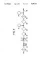
- FIG. 2shows an apparatus for depositing pure silica onto the end of a silica mandrel rotating about its axis and moved in slow translation away from the plasma and reagent gas feeds as the deposit grows;
- FIG. 3represents a desiccating line for the air fed into the closed chamber surrounding the mandrel, the plasma torch and the reagent gases injector.
- a piping means 1is used to introduce silicon tetrachloride into an evaporator 2, kept at a temperature as constant as possible.
- the vaporized silicon tetrachloridepasses through a heater 3, then through a flow controller 4 and a piping means 4A.
- a fluorine-containing gassuch as dichlorodifluoromethane, issuing from a bottle 5, flows via a a pressure controller 6 and a flow controller 7 to a piping means 10 joining with the silicon tetrachloride gas feed piping means 4A and likewise a stream of oxygen arriving via a piping means 8 and a flow controller 9.
- the reagent gasesare heated in a heater 11, then flow via the piping means 12 to the injector 12A bringing the reagent gases into contact with the plasma and the mandrel to be coated with a layer of fluorine-doped silica.
- a plasmagene gassuch as oxygen, nitrogen or argon
- a plasmagene gasis introduced into a torch 13 the end whereof is surrounded by a coil 14 supplied with high-frequency current by the generator 15.
- the ionized gas plasma at high temperatureforms a jet 16 that impinges on the periphery of the mandrel 17.
- the latterrotates about its axis and is driven by a rig 18 in smooth translation in a direction perpendicular to the plasma and reagent gas deliveries.
- the mandrel, the torch and the reagent gases injectorare arranged in a closed chamber 19 connected on the one hand to a dry air delivery nozzle 20 and on the other hand to a residual gas discharge pipe 21, connected to an exhaust gases cleaning installation.
- the apparatus for depositing pure silica onto the end of a mandrel, shown in FIG. 2,is broadly identical to the apparatus of FIG. 1
- the supply of silicon tetrachloride from the evaporator 2is similar. Since the deposit must be pure silica, the only other reagent gas is oxygen, arriving through pipe 8, flow controller 9 and pipe 10. The reagent gases are heated in heater 11 and then flow via pipe 12 to the injector 12A.
- a plasmagene gasis introduced into the plasma torch 13 surrounding by the coil 14 supplied with high frequency current by generator 15.
- a jet 16 of very high temperature plasmaforms at the outlet of the torch 13 to impinge on the end of the mandrel 12.
- the latterrotating about its axis, is driven by its rig 23 in a slow translation taking it gradually away from the torch and the reagent gases injector as the silica is deposited on the end of the mandrel.
- the mandrel, the plasma torch and the injectorare all located inside a closed chamber 19, supplied with dry air from the nozzle 20 and discharging the residual gas via a pipe 21 to a treatment installation.
- the atmospheric airis given a first cleaning to remove dust, organic vapors (oils) and hydrochloric vapors on an activated carbon filter 31.
- This airthen goes to a compressor 32, then to a water-based cooling means 33, where it is cooled by indirect contact with a cold water pipe coil 34.
- Itnext goes to a moisture-eliminating adsorber 36, consisting for example of a zeolite. It is connected downstream from this adsorber to a capacity reservoir 37 and then flows through a final adsorber 38 and a final filter 39 to a supply reservoir 40 feeding dry air through pipe 20 to the nozzle delivering dry air into the closed chamber surrounding the mandrel the plasma torch and the reagents injector.
- Such an air processing lineallows air with a residual water vapor content not exceeding one part per million by volume to be obtained.
- the inventionaccordingly makes it possible to effect silica deposits, either doped or not, with hydroxyl ion concentrations of less than 1 ppm and typically of the order of 0.1 ppm, usable for the manufacture of optical fibers with very low linear attenuation coefficients.
Landscapes
- Chemical & Material Sciences (AREA)
- Engineering & Computer Science (AREA)
- Materials Engineering (AREA)
- Organic Chemistry (AREA)
- General Chemical & Material Sciences (AREA)
- General Life Sciences & Earth Sciences (AREA)
- Geochemistry & Mineralogy (AREA)
- Manufacturing & Machinery (AREA)
- Chemical Kinetics & Catalysis (AREA)
- Life Sciences & Earth Sciences (AREA)
- Physics & Mathematics (AREA)
- Plasma & Fusion (AREA)
- Silicon Compounds (AREA)
- Manufacture, Treatment Of Glass Fibers (AREA)
- Glass Melting And Manufacturing (AREA)
- Surface Treatment Of Glass (AREA)
Abstract
Description
This invention concerns a method of outside deposition by substantially hydroxyl ion-free plasma, onto a silica rod, possibly doped to modify its refractive index, by reacting a silicon compound, such as SiCl4 for example, as well as any desired dopants, with oxygen in the presence of a plasma created by induction with the help of a high frequency generator. It also concerns a device for implementing the method.
The inventive method and device serve in particular to fabricate preforms intended to be subsequently transformed by drawing into optical fibers for telecommunications cables It is known that the linear attenuation coefficient of such optical fibers is closely related to the hydroxyl ion content of the silica from which they are made, such ions causing a certain absorption of the radiation in the wavelength ranges of the radiation habitually transmitted by the fibers, and at 1.4 micron in particular.
The presence of hydroxyl ions can be avoided to a very large extent in a layer of silica deposited on the inside of a tube that is rotated and heated on the outside by a torch moving in translation along the tube, due to the fact that it is possible to control the perfect dryness of the gaseous reagents introduced into the tube to direct the silica deposit onto the tube's inside wall. This control is lost when one wishes to deposit the silica onto the outside surface of a mandrel, heated by the impingement on its surface of a gas plasma at very high temperature simultaneously with the arrival of reagent gases designed to create the silica to be deposited.
This type of deposition can be made either on the entire outside surface of the mandrel, the latter being rotated about its axis and moved in translation relative to the arrivals of plasma and of reagent gases. It can also be made on the end of the mandrel, the gas plasma and the reagents injection being in this case directed to this end of the mandrel, in general to obtain a rod of pure silica. However, in both cases, the presence of moisture near the mandrel, and consequently the presence of hydroxyl ions in the silica deposited on the mandrel, cannot be avoided, the minimum hydroxyl ion concentrations int eh silica so obtained being in practice never less than a few tens of parts per million.
It is the object of the present invention to manufacture rods comprising an external layer of silica substantially free of hydroxyl ions, or silica rods substantially free of these ions, which can subsequently be used to make optical fibers with a very low linear attenuation coefficient.
The method according to the invention consists in maintaining the rod onto which the deposition of silica is made in a sealed enclosure separated from the surrounding atmosphere and supplied with atmospheric air which is successively subjected to filtering, to compression and cooling, to draining of the condensation water and to a final desiccation by adsorption.
The invention accordingly provides an apparatus, comprising a rod for receiving the silica deposit, a rig imparting rotation and translation to the rod, a torch delivering the plasmagene gas, an induction coil supplied by a high frequency generator around the end of the torch and a nozzle to inject towards the rod a mixture of oxygen and of a silicon compound, and possibly of doping compounds, wherein all of these elements are arranged inside a sealed enclosure separated from the surrounding atmosphere and supplied with atmospheric air by piping means equipped with at least a filter, a compressor, a cooling medium, a condensation water drain and a residual moisture adsorption bed.
Apparatus for depositing silica on a mandrel and an associated air desiccation line in accordance with the inventive method will now be described by way of example, with reference to the appended drawing in which:
FIG. 1 is a diagram of an apparatus for depositing doped silica onto the entire periphery of a silica mandrel made to rotate about its axis and to move in translation at a right angle to the arrivals of plasma and reagent gases;
FIG. 2 shows an apparatus for depositing pure silica onto the end of a silica mandrel rotating about its axis and moved in slow translation away from the plasma and reagent gas feeds as the deposit grows;
and FIG. 3 represents a desiccating line for the air fed into the closed chamber surrounding the mandrel, the plasma torch and the reagent gases injector.
As shown in FIG. 1, a piping means 1 is used to introduce silicon tetrachloride into an evaporator 2, kept at a temperature as constant as possible. The vaporized silicon tetrachloride passes through a heater 3, then through a flow controller 4 and a piping means 4A. At the same time, a fluorine-containing gas such as dichlorodifluoromethane, issuing from a bottle 5, flows via a a pressure controller 6 and a flow controller 7 to a piping means 10 joining with the silicon tetrachloride gas feed piping means 4A and likewise a stream of oxygen arriving via a piping means 8 and a flow controller 9. The reagent gases are heated in a heater 11, then flow via the piping means 12 to theinjector 12A bringing the reagent gases into contact with the plasma and the mandrel to be coated with a layer of fluorine-doped silica.
Also, a plasmagene gas, such as oxygen, nitrogen or argon, is introduced into atorch 13 the end whereof is surrounded by acoil 14 supplied with high-frequency current by thegenerator 15. The ionized gas plasma at high temperature forms ajet 16 that impinges on the periphery of themandrel 17. The latter rotates about its axis and is driven by arig 18 in smooth translation in a direction perpendicular to the plasma and reagent gas deliveries. The mandrel, the torch and the reagent gases injector are arranged in a closedchamber 19 connected on the one hand to a dryair delivery nozzle 20 and on the other hand to a residualgas discharge pipe 21, connected to an exhaust gases cleaning installation.
The apparatus for depositing pure silica onto the end of a mandrel, shown in FIG. 2, is broadly identical to the apparatus of FIG. 1 The supply of silicon tetrachloride from the evaporator 2 is similar. Since the deposit must be pure silica, the only other reagent gas is oxygen, arriving through pipe 8, flow controller 9 andpipe 10. The reagent gases are heated in heater 11 and then flow viapipe 12 to theinjector 12A.
In addition, a plasmagene gas is introduced into theplasma torch 13 surrounding by thecoil 14 supplied with high frequency current bygenerator 15. Ajet 16 of very high temperature plasma forms at the outlet of thetorch 13 to impinge on the end of themandrel 12. The latter, rotating about its axis, is driven by itsrig 23 in a slow translation taking it gradually away from the torch and the reagent gases injector as the silica is deposited on the end of the mandrel.
As in the previous embodiment, the mandrel, the plasma torch and the injector are all located inside a closedchamber 19, supplied with dry air from thenozzle 20 and discharging the residual gas via apipe 21 to a treatment installation.
In the air desiccating line represented in FIG. 3, the atmospheric air is given a first cleaning to remove dust, organic vapors (oils) and hydrochloric vapors on an activatedcarbon filter 31. This air then goes to acompressor 32, then to a water-based cooling means 33, where it is cooled by indirect contact with a coldwater pipe coil 34. It next goes to a moisture-eliminatingadsorber 36, consisting for example of a zeolite. It is connected downstream from this adsorber to acapacity reservoir 37 and then flows through afinal adsorber 38 and afinal filter 39 to asupply reservoir 40 feeding dry air throughpipe 20 to the nozzle delivering dry air into the closed chamber surrounding the mandrel the plasma torch and the reagents injector.
Such an air processing line allows air with a residual water vapor content not exceeding one part per million by volume to be obtained. The invention accordingly makes it possible to effect silica deposits, either doped or not, with hydroxyl ion concentrations of less than 1 ppm and typically of the order of 0.1 ppm, usable for the manufacture of optical fibers with very low linear attenuation coefficients.
Claims (9)
1. A method for plasma deposition of substantially hydroxyl ion-free silica onto the outer surface of a silica rod, comprising the steps of providing a sealed enclosure containing a rod, which sealed enclosure is separated from the surrounding atmosphere, reacting in the sealed chamber a silicon compound with oxygen in the presence of a plasma generated by induction with a high frequency generator to deposit silica onto the rod, wherein said enclosure is supplied with atmospheric air which has successively been subjected to filtering, compression and cooling, draining of condensation water and a final desiccation by adsorption.
2. The method of claim 1, wherein the silicon compound is silicon tetrachloride.
3. The method of claim 1, wherein a dopant is introduced into the plasma.
4. The method of claim 3, wherein the dopant is dichlorodifluoromethane.
5. The method of claim 1, wherein the treated atmospheric air supplied to the sealed enclosure has a water vapor content not exceeding one part per million by volume.
6. The method of claim 1, wherein the silica deposited on the rod has a hydroxyl ion content of less than 1 ppm.
7. The method of claim 6, wherein the silica deposited on the rod has a hydroxyl ion content of about 0.1 ppm.
8. The method of claim 1, wherein the silica as deposited onto the rod is pure, undoped silica.
9. A device for plasma deposition of substantially hydroxyl ion-free silica onto the outer surface of a silica rod, by reaction of a silicon compound with oxygen in the presence of a gas plasma generated by induction with a high frequency generator to deposit silica onto the rod, comprising a rod for receiving the silica deposit, a rig imparting rotation and translation to the rod, a torch delivering a plasmagene gas, an induction coil supplied by a high frequency generator around the end of the torch and a nozzle for injection towards the rod a mixture of oxygen and a silicon compound, all of these elements are arranged inside a sealed enclosure separated from the surrounding atmosphere, and wherein said enclosure is supplied with atmospheric air by piping means equipped with at least a filter, a compressor, a cooling medium, a condensation water drain and at least one residual moisture adsorption bed.
Applications Claiming Priority (2)
| Application Number | Priority Date | Filing Date | Title |
|---|---|---|---|
| FR8907391 | 1989-06-05 | ||
| FR8907391AFR2647778B1 (en) | 1989-06-05 | 1989-06-05 | METHOD AND DEVICE FOR EXTERNAL DEPOSITION BY HYDROXYLIC ION-FREE SILICA PLASMA |
Publications (1)
| Publication Number | Publication Date |
|---|---|
| US5194714Atrue US5194714A (en) | 1993-03-16 |
Family
ID=9382362
Family Applications (1)
| Application Number | Title | Priority Date | Filing Date |
|---|---|---|---|
| US07/533,557Expired - LifetimeUS5194714A (en) | 1989-06-05 | 1990-06-05 | Method and device for outside plasma deposition of hydroxyl ion-free silica |
Country Status (5)
| Country | Link |
|---|---|
| US (1) | US5194714A (en) |
| EP (1) | EP0401742B1 (en) |
| JP (1) | JPH0328140A (en) |
| DE (1) | DE69003175T2 (en) |
| FR (1) | FR2647778B1 (en) |
Cited By (53)
| Publication number | Priority date | Publication date | Assignee | Title |
|---|---|---|---|---|
| US5520891A (en)* | 1994-02-01 | 1996-05-28 | Lee; Jing M. | Cross-flow, fixed-bed catalytic reactor |
| US5554415A (en)* | 1994-01-18 | 1996-09-10 | Qqc, Inc. | Substrate coating techniques, including fabricating materials on a surface of a substrate |
| US5620754A (en)* | 1994-01-21 | 1997-04-15 | Qqc, Inc. | Method of treating and coating substrates |
| US5672192A (en)* | 1996-05-30 | 1997-09-30 | Lucent Technologies Inc. | Method of making optical fiber using a plasma torch fiber-drawing furnace |
| US5731046A (en)* | 1994-01-18 | 1998-03-24 | Qqc, Inc. | Fabrication of diamond and diamond-like carbon coatings |
| US5861047A (en)* | 1997-09-29 | 1999-01-19 | Lucent Technologies Inc. | Method for manufacturing an article comprising a refractory dielectric body |
| US5979190A (en)* | 1997-09-29 | 1999-11-09 | Lucent Technologies Inc. | Method for manufacturing an article comprising a refractory a dielectric body |
| DE29823926U1 (en) | 1997-12-19 | 2000-01-13 | Fibercore, Inc., Charlton, Mass. | Optical fiber glass semifinished product and device for producing a tubular member for optical fiber production |
| US6041623A (en)* | 1998-08-27 | 2000-03-28 | Lucent Technologies Inc. | Process for fabricating article comprising refractory dielectric body |
| GB2351287A (en)* | 1997-12-19 | 2000-12-27 | Fibercore Inc | Making optical fibre preforms using plasma outside vapour deposition |
| US20020005051A1 (en)* | 2000-04-28 | 2002-01-17 | Brown John T. | Substantially dry, silica-containing soot, fused silica and optical fiber soot preforms, apparatus, methods and burners for manufacturing same |
| US6354112B2 (en)* | 1997-12-03 | 2002-03-12 | Shin-Etsu Chemical Co., Ltd. | Method of depositing glass soot with controlling reaction chamber humidity to prevent accumulation of excess soot |
| US6474105B1 (en)* | 1994-12-29 | 2002-11-05 | Alcatel Cable | Modulating a diameter-increasing step of a fiber preform with no modulation prior to a predetermined diameter |
| US20030027054A1 (en)* | 2001-08-01 | 2003-02-06 | Ball Laura J. | Method for making photomask material by plasma induction |
| US20030070452A1 (en)* | 2001-10-12 | 2003-04-17 | Alcatel | Process for online spheroidization of quartz and silica particles |
| US6584806B2 (en)* | 2000-07-31 | 2003-07-01 | Alcatel | Method and apparatus for manufacturing an optical fiber preform |
| US20030182971A1 (en)* | 1999-07-01 | 2003-10-02 | Alcatel | Plasma torch, method of fabricating an optical fiber preform and preform fabrication system using the method |
| US20040050098A1 (en)* | 2001-08-01 | 2004-03-18 | Ball Laura J. | Method and feedstock for making photomask material |
| US6715321B1 (en) | 1999-03-08 | 2004-04-06 | Alcatel | Method of fabricating an optical fiber preform including outside deposition of silica, possibly doped silica |
| US6748768B2 (en) | 2000-12-15 | 2004-06-15 | Corning Incorporated | Apparatus and method of doping silica with fluorine during laydown |
| US20040206127A1 (en)* | 2003-03-31 | 2004-10-21 | Coffey Calvin T. | Method and apparatus for making soot |
| US20050120752A1 (en)* | 2001-04-11 | 2005-06-09 | Brown John T. | Substantially dry, silica-containing soot, fused silica and optical fiber soot preforms, apparatus, methods and burners for manufacturing same |
| US20050120751A1 (en)* | 2003-10-08 | 2005-06-09 | Draka Fibre Technology B.V. | Method for manufacturing a preform for optical fibres, as well as a method for manufacturing optical fibres |
| US20060272174A1 (en)* | 2005-05-20 | 2006-12-07 | Klaus Hartig | Deposition chamber desiccation systems and methods of use thereof |
| US20080250817A1 (en)* | 2007-03-27 | 2008-10-16 | Draka Comteq B.V. | Method and Apparatus for Manufacturing an Optical Fiber Preform |
| US20090159574A1 (en)* | 2007-12-19 | 2009-06-25 | Illinois Tool Works Inc. | Heat Exchanger and Moisture Removal for a Plasma Cutting System |
| US20100162768A1 (en)* | 2008-12-26 | 2010-07-01 | Shin-Etsu Chemical Co., Ltd. | Method and apparatus for manufacturing optical fiber preform using high frequency induction thermal plasma torch |
| EP2259105A1 (en) | 2009-06-05 | 2010-12-08 | Draka Comteq B.V. | Very broad bandwidth multimode optical fibre with an optimized core-cladding interface and reduced cladding effect |
| US20110016926A1 (en)* | 2009-07-27 | 2011-01-27 | Shin-Etsu Chemical Co., Ltd. | Method of manufacturing optical fiber preform using plasma torch |
| US20110058781A1 (en)* | 2009-09-09 | 2011-03-10 | Draka Comteq, B.V. | Multimode Optical Fiber Having Improved Bending Losses |
| US20110064367A1 (en)* | 2009-09-17 | 2011-03-17 | Draka Comteq, B.V. | Multimode Optical Fiber |
| US20110123162A1 (en)* | 2009-11-25 | 2011-05-26 | Draka Comteq, B.V. | High-Bandwidth, Dual-Trench-Assisted Multimode Optical Fiber |
| US20110123161A1 (en)* | 2009-11-25 | 2011-05-26 | Draka Comteq B.V. | High-Bandwidth Multimode Optical Fiber with Reduced Cladding Effect |
| US20110135262A1 (en)* | 2009-12-03 | 2011-06-09 | Draka Comteq, B.V. | Multimode Optical Fiber with Low Bending Losses and Reduced Cladding Effect |
| US20110135263A1 (en)* | 2009-12-03 | 2011-06-09 | Draka Comteq, B.V. | High-Bandwidth Multimode Optical Fiber Having Reduced Bending Losses |
| US20110188826A1 (en)* | 2010-02-01 | 2011-08-04 | Draka Comteq B.V. | Non-Zero Dispersion Shifted Optical Fiber Having a Large Effective Area |
| US20110188823A1 (en)* | 2010-02-01 | 2011-08-04 | Draka Comteq B.V. | Non-Zero Dispersion Shifted Optical Fiber Having a Short Cutoff Wavelength |
| US20110217012A1 (en)* | 2010-03-02 | 2011-09-08 | Draka Comteq B.V. | Broad-Bandwidth Multimode Optical Fiber Having Reduced Bending Losses |
| US20110229101A1 (en)* | 2010-03-17 | 2011-09-22 | Draka Comteq B.V. | Single-Mode Optical Fiber |
| US20120061230A1 (en)* | 2009-03-10 | 2012-03-15 | Advanced Nuclear Fuels Gmbh | Suction device for gases or fumes, in particular welding fumes, having an oxidation apparatus, welding system and associated method |
| CN102705205A (en)* | 2012-05-28 | 2012-10-03 | 深圳百时得能源环保科技有限公司 | Pre-treating and variable-flow device of air compression system |
| US8391661B2 (en) | 2011-01-31 | 2013-03-05 | Draka Comteq, B.V. | Multimode optical fiber |
| US8639079B2 (en) | 2011-03-29 | 2014-01-28 | Draka Comteq, B.V. | Multimode optical fiber |
| US8644664B2 (en) | 2011-01-31 | 2014-02-04 | Draka Comteq, B.V. | Broad-bandwidth optical fiber |
| US8867879B2 (en) | 2010-07-02 | 2014-10-21 | Draka Comteq, B.V. | Single-mode optical fiber |
| US8879878B2 (en) | 2011-07-01 | 2014-11-04 | Draka Comteq, B.V. | Multimode optical fiber |
| US8891074B2 (en) | 2010-10-18 | 2014-11-18 | Draka Comteq, B.V. | Multimode optical fiber insensitive to bending losses |
| US9014525B2 (en) | 2009-09-09 | 2015-04-21 | Draka Comteq, B.V. | Trench-assisted multimode optical fiber |
| US9162917B2 (en) | 2011-03-04 | 2015-10-20 | Draka Comteq, B.V. | Rare-earth-doped amplifying optical fiber |
| US9341771B2 (en) | 2011-03-24 | 2016-05-17 | Draka Comteq, B.V. | Bend-resistant multimode optical fiber |
| US9405062B2 (en) | 2011-04-27 | 2016-08-02 | Draka Comteq B.V. | High-bandwidth, radiation-resistant multimode optical fiber |
| US9563012B2 (en) | 2012-04-27 | 2017-02-07 | Draka Comteq, B.V. | Hybrid single-mode and multimode optical fiber |
| CN111847866A (en)* | 2020-07-14 | 2020-10-30 | 复旦大学 | Low-loss optical fiber preform outer cladding and preparation equipment and preparation method and optical fiber |
Families Citing this family (8)
| Publication number | Priority date | Publication date | Assignee | Title |
|---|---|---|---|---|
| FR2713621B1 (en)* | 1993-12-14 | 1996-01-05 | Alcatel Fibres Optiques | Method for plasma recharging of a preform for optical fiber and optical fiber originating from the preform recharged according to this method. |
| IT1308786B1 (en)* | 1999-07-05 | 2002-01-10 | Cselt Centro Studi Lab Telecom | PROCESS AND EQUIPMENT FOR THE FORMATION OF GLASS DISILICE FLAT LAYERS THROUGH THE USE OF A COUPLING PLASMA TORCH |
| DE10035951C2 (en)* | 2000-07-21 | 2002-06-27 | Heraeus Quarzglas | Process for producing a component for the production of optical fibers, and use of the component |
| FR2847893B1 (en)* | 2002-12-02 | 2006-05-05 | Cit Alcatel | METHOD AND DEVICE FOR PLASMA RECHARGING A PREFORM FOR OPTICAL FIBER WITH REDUCED NITROGEN OXIDES |
| FR2895396B1 (en)* | 2005-12-23 | 2008-02-22 | Draka Comteq France | PROCESS FOR PRODUCING AN OPTICAL FIBER PREFORM |
| JP5380018B2 (en) | 2008-09-03 | 2014-01-08 | 株式会社フジクラ | Optical fiber preform manufacturing method |
| JP4926165B2 (en)* | 2008-12-26 | 2012-05-09 | 信越化学工業株式会社 | Optical fiber preform manufacturing method and apparatus using high frequency induction thermal plasma torch |
| NL2014519B1 (en) | 2015-03-25 | 2017-01-25 | Draka Comteq Bv | A rotary feed-through for mounting a rotating substrate tube in a lathe, a CVD lathe and a corresponding method using the CVD lathe. |
Citations (11)
| Publication number | Priority date | Publication date | Assignee | Title |
|---|---|---|---|---|
| US4162908A (en)* | 1975-08-16 | 1979-07-31 | Heraeus Quarzschmelze Gmbh | Method of producing synthetic quartz glass, apparatus for the practice of the method, and use of the synthetic quartz glass |
| JPS5697522A (en)* | 1980-01-07 | 1981-08-06 | Toho Gas Kk | Room cooler with dehumidifyer |
| US4441788A (en)* | 1980-12-16 | 1984-04-10 | Quartz Et Silice | Optical wave guide with fluorine-doped core |
| DE3404119A1 (en)* | 1984-02-07 | 1985-08-08 | Merck Patent Gmbh, 6100 Darmstadt | Transport and removal device |
| DE3420790A1 (en)* | 1984-06-04 | 1985-12-05 | Siemens AG, 1000 Berlin und 8000 München | Process and device for producing a blank for optical waveguides |
| US4583997A (en)* | 1983-10-25 | 1986-04-22 | Wacker-Chemitronic Gesellschaft Fur Elektronik Grundstoffe Mbh | Process for reducing the hydroxyl content of optical waveguides |
| US4740226A (en)* | 1986-01-27 | 1988-04-26 | Sumitomo Electric Industries, Ltd. | Apparatus for the production of porous preform of optical fiber |
| US4793832A (en)* | 1986-04-14 | 1988-12-27 | Fmc Corporation | Air purification and temperature controlling system and method |
| JPH01236920A (en)* | 1988-03-18 | 1989-09-21 | Hitachi Ltd | Absorption type refrigeration dehumidifier |
| US4881953A (en)* | 1988-09-15 | 1989-11-21 | Union Carbide Corporation | Prevention of membrane degradation |
| US4957516A (en)* | 1987-10-22 | 1990-09-18 | Reading Technologies, Inc. | Inverse flow depth filter assembly |
- 1989
- 1989-06-05FRFR8907391Apatent/FR2647778B1/ennot_activeExpired - Lifetime
- 1990
- 1990-06-04JPJP2146046Apatent/JPH0328140A/enactivePending
- 1990-06-05EPEP90110603Apatent/EP0401742B1/ennot_activeExpired - Lifetime
- 1990-06-05DEDE90110603Tpatent/DE69003175T2/ennot_activeExpired - Lifetime
- 1990-06-05USUS07/533,557patent/US5194714A/ennot_activeExpired - Lifetime
Patent Citations (11)
| Publication number | Priority date | Publication date | Assignee | Title |
|---|---|---|---|---|
| US4162908A (en)* | 1975-08-16 | 1979-07-31 | Heraeus Quarzschmelze Gmbh | Method of producing synthetic quartz glass, apparatus for the practice of the method, and use of the synthetic quartz glass |
| JPS5697522A (en)* | 1980-01-07 | 1981-08-06 | Toho Gas Kk | Room cooler with dehumidifyer |
| US4441788A (en)* | 1980-12-16 | 1984-04-10 | Quartz Et Silice | Optical wave guide with fluorine-doped core |
| US4583997A (en)* | 1983-10-25 | 1986-04-22 | Wacker-Chemitronic Gesellschaft Fur Elektronik Grundstoffe Mbh | Process for reducing the hydroxyl content of optical waveguides |
| DE3404119A1 (en)* | 1984-02-07 | 1985-08-08 | Merck Patent Gmbh, 6100 Darmstadt | Transport and removal device |
| DE3420790A1 (en)* | 1984-06-04 | 1985-12-05 | Siemens AG, 1000 Berlin und 8000 München | Process and device for producing a blank for optical waveguides |
| US4740226A (en)* | 1986-01-27 | 1988-04-26 | Sumitomo Electric Industries, Ltd. | Apparatus for the production of porous preform of optical fiber |
| US4793832A (en)* | 1986-04-14 | 1988-12-27 | Fmc Corporation | Air purification and temperature controlling system and method |
| US4957516A (en)* | 1987-10-22 | 1990-09-18 | Reading Technologies, Inc. | Inverse flow depth filter assembly |
| JPH01236920A (en)* | 1988-03-18 | 1989-09-21 | Hitachi Ltd | Absorption type refrigeration dehumidifier |
| US4881953A (en)* | 1988-09-15 | 1989-11-21 | Union Carbide Corporation | Prevention of membrane degradation |
Cited By (86)
| Publication number | Priority date | Publication date | Assignee | Title |
|---|---|---|---|---|
| US5554415A (en)* | 1994-01-18 | 1996-09-10 | Qqc, Inc. | Substrate coating techniques, including fabricating materials on a surface of a substrate |
| US5731046A (en)* | 1994-01-18 | 1998-03-24 | Qqc, Inc. | Fabrication of diamond and diamond-like carbon coatings |
| US5620754A (en)* | 1994-01-21 | 1997-04-15 | Qqc, Inc. | Method of treating and coating substrates |
| US5520891A (en)* | 1994-02-01 | 1996-05-28 | Lee; Jing M. | Cross-flow, fixed-bed catalytic reactor |
| US6474105B1 (en)* | 1994-12-29 | 2002-11-05 | Alcatel Cable | Modulating a diameter-increasing step of a fiber preform with no modulation prior to a predetermined diameter |
| US5672192A (en)* | 1996-05-30 | 1997-09-30 | Lucent Technologies Inc. | Method of making optical fiber using a plasma torch fiber-drawing furnace |
| US5861047A (en)* | 1997-09-29 | 1999-01-19 | Lucent Technologies Inc. | Method for manufacturing an article comprising a refractory dielectric body |
| US5979190A (en)* | 1997-09-29 | 1999-11-09 | Lucent Technologies Inc. | Method for manufacturing an article comprising a refractory a dielectric body |
| US6354112B2 (en)* | 1997-12-03 | 2002-03-12 | Shin-Etsu Chemical Co., Ltd. | Method of depositing glass soot with controlling reaction chamber humidity to prevent accumulation of excess soot |
| GB2351287A (en)* | 1997-12-19 | 2000-12-27 | Fibercore Inc | Making optical fibre preforms using plasma outside vapour deposition |
| GB2351287B (en)* | 1997-12-19 | 2002-02-27 | Fibercore Inc | Method of making a tubular member for optical fiber production using plasma outside vapor deposition |
| DE29823926U1 (en) | 1997-12-19 | 2000-01-13 | Fibercore, Inc., Charlton, Mass. | Optical fiber glass semifinished product and device for producing a tubular member for optical fiber production |
| US6041623A (en)* | 1998-08-27 | 2000-03-28 | Lucent Technologies Inc. | Process for fabricating article comprising refractory dielectric body |
| US6715321B1 (en) | 1999-03-08 | 2004-04-06 | Alcatel | Method of fabricating an optical fiber preform including outside deposition of silica, possibly doped silica |
| US20030182971A1 (en)* | 1999-07-01 | 2003-10-02 | Alcatel | Plasma torch, method of fabricating an optical fiber preform and preform fabrication system using the method |
| US20060288739A1 (en)* | 1999-07-01 | 2006-12-28 | Draka Comteq B.V. | Plasma torch and preform fabrication system using the method |
| US7121120B2 (en) | 1999-07-01 | 2006-10-17 | Alcatel | Method of glazing an optical fiber preform with a plasma of reduced power |
| US7089766B2 (en) | 2000-04-28 | 2006-08-15 | Corning Inc | Method of forming optical fiber preforms |
| US20020005051A1 (en)* | 2000-04-28 | 2002-01-17 | Brown John T. | Substantially dry, silica-containing soot, fused silica and optical fiber soot preforms, apparatus, methods and burners for manufacturing same |
| US20050155388A1 (en)* | 2000-04-28 | 2005-07-21 | Burke Gerald E. | Substantially dry, silica-containing soot, fused silica and optical fiber soot preforms, apparatus, methods and burners for manufacturing same |
| US6584806B2 (en)* | 2000-07-31 | 2003-07-01 | Alcatel | Method and apparatus for manufacturing an optical fiber preform |
| US6748768B2 (en) | 2000-12-15 | 2004-06-15 | Corning Incorporated | Apparatus and method of doping silica with fluorine during laydown |
| US20050120752A1 (en)* | 2001-04-11 | 2005-06-09 | Brown John T. | Substantially dry, silica-containing soot, fused silica and optical fiber soot preforms, apparatus, methods and burners for manufacturing same |
| US20040050098A1 (en)* | 2001-08-01 | 2004-03-18 | Ball Laura J. | Method and feedstock for making photomask material |
| US20030027054A1 (en)* | 2001-08-01 | 2003-02-06 | Ball Laura J. | Method for making photomask material by plasma induction |
| US20030070452A1 (en)* | 2001-10-12 | 2003-04-17 | Alcatel | Process for online spheroidization of quartz and silica particles |
| US20040206127A1 (en)* | 2003-03-31 | 2004-10-21 | Coffey Calvin T. | Method and apparatus for making soot |
| US20050120751A1 (en)* | 2003-10-08 | 2005-06-09 | Draka Fibre Technology B.V. | Method for manufacturing a preform for optical fibres, as well as a method for manufacturing optical fibres |
| US8006518B2 (en)* | 2003-10-08 | 2011-08-30 | Draka Comteq, B.V. | Method for manufacturing a preform for optical fibres |
| US8484996B2 (en) | 2003-10-08 | 2013-07-16 | Draka Comteq B.V. | Method of manufacturing an optical fibre preform |
| US20060272174A1 (en)* | 2005-05-20 | 2006-12-07 | Klaus Hartig | Deposition chamber desiccation systems and methods of use thereof |
| US20080250817A1 (en)* | 2007-03-27 | 2008-10-16 | Draka Comteq B.V. | Method and Apparatus for Manufacturing an Optical Fiber Preform |
| US8153925B2 (en)* | 2007-12-19 | 2012-04-10 | Illinois Tool Works Inc. | Heat exchanger and moisture removal for a plasma cutting system |
| US20090159574A1 (en)* | 2007-12-19 | 2009-06-25 | Illinois Tool Works Inc. | Heat Exchanger and Moisture Removal for a Plasma Cutting System |
| EP2206689A1 (en)* | 2008-12-26 | 2010-07-14 | Shin-Etsu Chemical Co., Ltd. | Method and apparatus for manufacturing optical fiber preform using high frequency induction thermal plasma torch |
| US20100162768A1 (en)* | 2008-12-26 | 2010-07-01 | Shin-Etsu Chemical Co., Ltd. | Method and apparatus for manufacturing optical fiber preform using high frequency induction thermal plasma torch |
| US20120061230A1 (en)* | 2009-03-10 | 2012-03-15 | Advanced Nuclear Fuels Gmbh | Suction device for gases or fumes, in particular welding fumes, having an oxidation apparatus, welding system and associated method |
| US20100310218A1 (en)* | 2009-06-05 | 2010-12-09 | Draka Comteq B.V. | Large Bandwidth Multimode Optical Fiber Having a Reduced Cladding Effect |
| EP2259105A1 (en) | 2009-06-05 | 2010-12-08 | Draka Comteq B.V. | Very broad bandwidth multimode optical fibre with an optimized core-cladding interface and reduced cladding effect |
| US8867880B2 (en) | 2009-06-05 | 2014-10-21 | Draka Comteq, B.V. | Large bandwidth multimode optical fiber having a reduced cladding effect |
| US8707741B2 (en) | 2009-07-27 | 2014-04-29 | Shin-Etsu Chemical Co., Ltd | Method of manufacturing optical fiber preform using plasma torch |
| EP2287119A1 (en)* | 2009-07-27 | 2011-02-23 | Shin-Etsu Chemical Co., Ltd. | Method of manufacturing optical fiber preform using plasma torch |
| US20110016926A1 (en)* | 2009-07-27 | 2011-01-27 | Shin-Etsu Chemical Co., Ltd. | Method of manufacturing optical fiber preform using plasma torch |
| US9014525B2 (en) | 2009-09-09 | 2015-04-21 | Draka Comteq, B.V. | Trench-assisted multimode optical fiber |
| EP2299302A1 (en) | 2009-09-09 | 2011-03-23 | Draka Comteq B.V. | Multimode optical fibre having improved bending losses |
| US8520993B2 (en) | 2009-09-09 | 2013-08-27 | Draka Comteq, B.V. | Multimode optical fiber having improved bending losses |
| US20110058781A1 (en)* | 2009-09-09 | 2011-03-10 | Draka Comteq, B.V. | Multimode Optical Fiber Having Improved Bending Losses |
| EP2299303A2 (en) | 2009-09-17 | 2011-03-23 | Draka Comteq B.V. | Multimode optical fibre with reduced bending loss |
| US20110064367A1 (en)* | 2009-09-17 | 2011-03-17 | Draka Comteq, B.V. | Multimode Optical Fiber |
| US8340488B2 (en) | 2009-09-17 | 2012-12-25 | Draka Comteq, B.V. | Multimode optical fiber |
| US20110123161A1 (en)* | 2009-11-25 | 2011-05-26 | Draka Comteq B.V. | High-Bandwidth Multimode Optical Fiber with Reduced Cladding Effect |
| US8385704B2 (en) | 2009-11-25 | 2013-02-26 | Draka Comteq Bv | High-bandwidth multimode optical fiber with reduced cladding effect |
| US20110123162A1 (en)* | 2009-11-25 | 2011-05-26 | Draka Comteq, B.V. | High-Bandwidth, Dual-Trench-Assisted Multimode Optical Fiber |
| EP2333593A1 (en) | 2009-11-25 | 2011-06-15 | Draka Comteq B.V. | High bandwidth multimode optical fiber |
| EP2333594A1 (en) | 2009-11-25 | 2011-06-15 | Draka Comteq B.V. | High bandwidth multimode optical fiber |
| US8483535B2 (en) | 2009-11-25 | 2013-07-09 | Draka Comteq B.V. | High-bandwidth, dual-trench-assisted multimode optical fiber |
| US8280213B2 (en) | 2009-11-25 | 2012-10-02 | Draka Comteq, B.V. | High-bandwidth multimode optical fiber with reduced cladding effect |
| EP2339383A1 (en) | 2009-12-03 | 2011-06-29 | Draka Comteq B.V. | Multimode optical fiber with low bending losses and reduced cladding effect |
| EP2339384A1 (en) | 2009-12-03 | 2011-06-29 | Draka Comteq B.V. | High-bandwidth multimode optical fiber having reduced bending losses |
| US20110135262A1 (en)* | 2009-12-03 | 2011-06-09 | Draka Comteq, B.V. | Multimode Optical Fiber with Low Bending Losses and Reduced Cladding Effect |
| US20110135263A1 (en)* | 2009-12-03 | 2011-06-09 | Draka Comteq, B.V. | High-Bandwidth Multimode Optical Fiber Having Reduced Bending Losses |
| US8406593B2 (en) | 2009-12-03 | 2013-03-26 | Draka Comteq B.V. | Multimode optical fiber with low bending losses and reduced cladding effect |
| US8428410B2 (en) | 2009-12-03 | 2013-04-23 | Draka Comteq B.V. | High-bandwidth multimode optical fiber having reduced bending losses |
| US8676015B2 (en) | 2010-02-01 | 2014-03-18 | Draka Comteq, B.V. | Non-zero dispersion shifted optical fiber having a short cutoff wavelength |
| US20110188823A1 (en)* | 2010-02-01 | 2011-08-04 | Draka Comteq B.V. | Non-Zero Dispersion Shifted Optical Fiber Having a Short Cutoff Wavelength |
| US20110188826A1 (en)* | 2010-02-01 | 2011-08-04 | Draka Comteq B.V. | Non-Zero Dispersion Shifted Optical Fiber Having a Large Effective Area |
| US8983260B2 (en) | 2010-02-01 | 2015-03-17 | Draka Comteq, B.V. | Non-zero dispersion shifted optical fiber having a large effective area |
| US8565568B2 (en) | 2010-03-02 | 2013-10-22 | Draka Comteq, B.V. | Broad-bandwidth multimode optical fiber having reduced bending losses |
| US20110217012A1 (en)* | 2010-03-02 | 2011-09-08 | Draka Comteq B.V. | Broad-Bandwidth Multimode Optical Fiber Having Reduced Bending Losses |
| US20110229101A1 (en)* | 2010-03-17 | 2011-09-22 | Draka Comteq B.V. | Single-Mode Optical Fiber |
| US8428411B2 (en) | 2010-03-17 | 2013-04-23 | Draka Comteq, B.V. | Single-mode optical fiber |
| US8867879B2 (en) | 2010-07-02 | 2014-10-21 | Draka Comteq, B.V. | Single-mode optical fiber |
| US8891074B2 (en) | 2010-10-18 | 2014-11-18 | Draka Comteq, B.V. | Multimode optical fiber insensitive to bending losses |
| US8644664B2 (en) | 2011-01-31 | 2014-02-04 | Draka Comteq, B.V. | Broad-bandwidth optical fiber |
| US8391661B2 (en) | 2011-01-31 | 2013-03-05 | Draka Comteq, B.V. | Multimode optical fiber |
| US9162917B2 (en) | 2011-03-04 | 2015-10-20 | Draka Comteq, B.V. | Rare-earth-doped amplifying optical fiber |
| US9341771B2 (en) | 2011-03-24 | 2016-05-17 | Draka Comteq, B.V. | Bend-resistant multimode optical fiber |
| US9671553B2 (en) | 2011-03-24 | 2017-06-06 | Draka Comteq, B.V. | Bend-resistant multimode optical fiber |
| US8639079B2 (en) | 2011-03-29 | 2014-01-28 | Draka Comteq, B.V. | Multimode optical fiber |
| US9405062B2 (en) | 2011-04-27 | 2016-08-02 | Draka Comteq B.V. | High-bandwidth, radiation-resistant multimode optical fiber |
| US8879878B2 (en) | 2011-07-01 | 2014-11-04 | Draka Comteq, B.V. | Multimode optical fiber |
| US9563012B2 (en) | 2012-04-27 | 2017-02-07 | Draka Comteq, B.V. | Hybrid single-mode and multimode optical fiber |
| US9869814B2 (en) | 2012-04-27 | 2018-01-16 | Draka Comteq, B.V. | Hybrid single-mode and multimode optical fiber |
| CN102705205A (en)* | 2012-05-28 | 2012-10-03 | 深圳百时得能源环保科技有限公司 | Pre-treating and variable-flow device of air compression system |
| CN102705205B (en)* | 2012-05-28 | 2015-12-23 | 深圳百时得能源环保科技有限公司 | A kind of pretreatment of air compression system and variable-flow device |
| CN111847866A (en)* | 2020-07-14 | 2020-10-30 | 复旦大学 | Low-loss optical fiber preform outer cladding and preparation equipment and preparation method and optical fiber |
Also Published As
| Publication number | Publication date |
|---|---|
| FR2647778A1 (en) | 1990-12-07 |
| DE69003175T2 (en) | 1994-01-05 |
| DE69003175D1 (en) | 1993-10-14 |
| FR2647778B1 (en) | 1992-11-20 |
| JPH0328140A (en) | 1991-02-06 |
| EP0401742A1 (en) | 1990-12-12 |
| EP0401742B1 (en) | 1993-09-08 |
Similar Documents
| Publication | Publication Date | Title |
|---|---|---|
| US5194714A (en) | Method and device for outside plasma deposition of hydroxyl ion-free silica | |
| US5139999A (en) | Chemical vapor deposition process where an alkaline earth metal organic precursor material is volatilized in the presence of an amine or ammonia and deposited onto a substrate | |
| EP0299753B1 (en) | Controlled flow vaporizer | |
| EP0299754A2 (en) | Method of plasma enhanced silicon oxide deposition | |
| US4936940A (en) | Equipment for surface treatment | |
| CN1252778A (en) | Method of making a tubular member for optical fiber production using plasma outside vapor deposition | |
| US20080081130A1 (en) | Treatment of effluent in the deposition of carbon-doped silicon | |
| EP0245716A1 (en) | Method and apparatus for forming doped optical preforms | |
| US4608276A (en) | Manufacturing optical fibre | |
| US10435787B2 (en) | Hydrogen partial pressure control in a vacuum process chamber | |
| CA1291645C (en) | Method of manufacturing solid glass preforms from hollow preforms | |
| Inoue et al. | Spectroscopic studies on preparation of silicon oxide films by PECVD using organosilicon compounds | |
| JPH0653595B2 (en) | Method and apparatus for on-line coating of quartz fiber with boron nitride | |
| US4651673A (en) | CVD apparatus | |
| CN1986467B (en) | Method and apparatus for manufacturing low oh overcladding | |
| US5906861A (en) | Apparatus and method for depositing borophosphosilicate glass on a substrate | |
| US4518455A (en) | CVD Process | |
| CN1623941B (en) | System for forming a gas flow of reactants for a doped glass material | |
| JPH0680413A (en) | Method for chemical vapor growth of silicon dioxide film | |
| KR100378497B1 (en) | Gas distribution system for a process reactor and method for processing semiconductor substrates | |
| JP2004161555A (en) | Method for supplying glass forming gas, method for producing glass fine particle deposit, and respective apparatuses | |
| JP2003238191A (en) | Heating apparatus for glass body and manufacturing method using the same | |
| EP4219416A1 (en) | Method for manufacturing fluorine-containing silica glass | |
| JPH0677145A (en) | Thin film formation method | |
| RU2013819C1 (en) | Process of manufacture of layers of silicon oxide |
Legal Events
| Date | Code | Title | Description |
|---|---|---|---|
| AS | Assignment | Owner name:COMPAGNIE GENERALE D 'ELECTRICITE, FRANCE Free format text:ASSIGNMENT OF ASSIGNORS INTEREST.;ASSIGNOR:LE SERGENT, CHRISTIAN;REEL/FRAME:006332/0375 Effective date:19900525 | |
| STCF | Information on status: patent grant | Free format text:PATENTED CASE | |
| FEPP | Fee payment procedure | Free format text:PAYER NUMBER DE-ASSIGNED (ORIGINAL EVENT CODE: RMPN); ENTITY STATUS OF PATENT OWNER: LARGE ENTITY Free format text:PAYOR NUMBER ASSIGNED (ORIGINAL EVENT CODE: ASPN); ENTITY STATUS OF PATENT OWNER: LARGE ENTITY | |
| FEPP | Fee payment procedure | Free format text:PAYOR NUMBER ASSIGNED (ORIGINAL EVENT CODE: ASPN); ENTITY STATUS OF PATENT OWNER: LARGE ENTITY | |
| FPAY | Fee payment | Year of fee payment:4 | |
| FPAY | Fee payment | Year of fee payment:8 | |
| SULP | Surcharge for late payment | Year of fee payment:7 | |
| FPAY | Fee payment | Year of fee payment:12 |