US5193547A - Universal connector means for transducer/monitor systems - Google Patents
Universal connector means for transducer/monitor systemsDownload PDFInfo
- Publication number
- US5193547A US5193547AUS06/945,381US94538186AUS5193547AUS 5193547 AUS5193547 AUS 5193547AUS 94538186 AUS94538186 AUS 94538186AUS 5193547 AUS5193547 AUS 5193547A
- Authority
- US
- United States
- Prior art keywords
- transducer
- impedance
- monitor
- blood pressure
- output
- Prior art date
- Legal status (The legal status is an assumption and is not a legal conclusion. Google has not performed a legal analysis and makes no representation as to the accuracy of the status listed.)
- Expired - Lifetime
Links
Images

Classifications
- H—ELECTRICITY
- H03—ELECTRONIC CIRCUITRY
- H03F—AMPLIFIERS
- H03F3/00—Amplifiers with only discharge tubes or only semiconductor devices as amplifying elements
- H03F3/45—Differential amplifiers
- H03F3/45071—Differential amplifiers with semiconductor devices only
- H03F3/45479—Differential amplifiers with semiconductor devices only characterised by the way of common mode signal rejection
- H03F3/45928—Differential amplifiers with semiconductor devices only characterised by the way of common mode signal rejection using IC blocks as the active amplifying circuit
- H03F3/4595—Differential amplifiers with semiconductor devices only characterised by the way of common mode signal rejection using IC blocks as the active amplifying circuit by using feedforward means
- H03F3/45955—Measuring at the input circuit of the differential amplifier
- H03F3/45959—Controlling the input circuit of the differential amplifier
- A—HUMAN NECESSITIES
- A61—MEDICAL OR VETERINARY SCIENCE; HYGIENE
- A61B—DIAGNOSIS; SURGERY; IDENTIFICATION
- A61B5/00—Measuring for diagnostic purposes; Identification of persons
- A61B5/02—Detecting, measuring or recording for evaluating the cardiovascular system, e.g. pulse, heart rate, blood pressure or blood flow
- A61B5/021—Measuring pressure in heart or blood vessels
- A—HUMAN NECESSITIES
- A61—MEDICAL OR VETERINARY SCIENCE; HYGIENE
- A61B—DIAGNOSIS; SURGERY; IDENTIFICATION
- A61B5/00—Measuring for diagnostic purposes; Identification of persons
- A61B5/24—Detecting, measuring or recording bioelectric or biomagnetic signals of the body or parts thereof
- A61B5/30—Input circuits therefor
- A61B5/305—Common mode rejection
- A—HUMAN NECESSITIES
- A61—MEDICAL OR VETERINARY SCIENCE; HYGIENE
- A61B—DIAGNOSIS; SURGERY; IDENTIFICATION
- A61B5/00—Measuring for diagnostic purposes; Identification of persons
- A61B5/24—Detecting, measuring or recording bioelectric or biomagnetic signals of the body or parts thereof
- A61B5/30—Input circuits therefor
- A61B5/307—Input circuits therefor specially adapted for particular uses
- H—ELECTRICITY
- H03—ELECTRONIC CIRCUITRY
- H03F—AMPLIFIERS
- H03F3/00—Amplifiers with only discharge tubes or only semiconductor devices as amplifying elements
- H03F3/45—Differential amplifiers
- H03F3/45071—Differential amplifiers with semiconductor devices only
- H03F3/45076—Differential amplifiers with semiconductor devices only characterised by the way of implementation of the active amplifying circuit in the differential amplifier
- H03F3/45475—Differential amplifiers with semiconductor devices only characterised by the way of implementation of the active amplifying circuit in the differential amplifier using IC blocks as the active amplifying circuit
- H—ELECTRICITY
- H03—ELECTRONIC CIRCUITRY
- H03F—AMPLIFIERS
- H03F3/00—Amplifiers with only discharge tubes or only semiconductor devices as amplifying elements
- H03F3/45—Differential amplifiers
- H03F3/45071—Differential amplifiers with semiconductor devices only
- H03F3/45479—Differential amplifiers with semiconductor devices only characterised by the way of common mode signal rejection
- A—HUMAN NECESSITIES
- A61—MEDICAL OR VETERINARY SCIENCE; HYGIENE
- A61B—DIAGNOSIS; SURGERY; IDENTIFICATION
- A61B2560/00—Constructional details of operational features of apparatus; Accessories for medical measuring apparatus
- A61B2560/04—Constructional details of apparatus
- A61B2560/0443—Modular apparatus
- A61B2560/045—Modular apparatus with a separable interface unit, e.g. for communication
Definitions
- This inventionelates to systems for detecting blood pressure un humans, for converting the detected blood pressure into electrical signals, and for displaying, recording or otherwise monitoring these electrical signals promptly after detection.
- Such systemsinclude a blood-pressure transducer that is attached to he arterial or venous system of a human, a blood-pressure monitor that indicates blood pressure, and our new, universal connector/cable assembly, the connector.
- the connectoris compatible with many different types of blood-pressure transducers and with many different kinds of blood-pressure monitors.
- the input-output transfer function of a systemis affected by the conditions existing at he input and output ports, so that a meaningful specification of the transfer function must also includes statement as to what these conditions are.
- the throughputmay well be affected by changes in pressure at the input and output ports.
- a proper specification of the performanceshould include graphs showing the variation of throughput with input and output port pressures. In a generalized system these pressures correspond to the input and output load conditions.
- the generalized input impedance and output impedanceQuantities that conveniently characterize the input and output properties of most systems are the generalized input impedance and output impedance. Although these quantities are usually associated with purely electrical systems, they can also be conveniently applied to mechanical and hydraulic systems. Thus, one speaks of the mechanical input and output impedances.
- the generalized impedance Zis defined by
- Zhas a magnitude and phase values of which may be frequency-dependent.
- Zis the ratio of the voltage to the current
- the input impedancecan be found by applying a known sinusoidal emf to the input and measuring the input current.
- the output impedancecan be found by applying an emf to the output terminals and measuring the output current.
- the inventionrelates to systems for detecting physiological conditions in humans or other animals, for converting the detected physiological conditions into electrical signals, and for displaying, recording or otherwise monitoring these electrical signals promptly after detection.
- the transducercan detect such physiological conditions as temperature, blood gas levels and hematocrit levels.
- Our new, universal connector/cable assemblyis compatible with many different kinds of transducers and monitors.
- our new connectorpermits linking a wide variety of transducers to a wide variety of monitors.
- this connectoris compatible with many different kinds of blood pressure transducers, including disposable and reusable transducers, and with a wide variety of commercially available blood-pressure monitors.
- the connectorcan be adapted for use with monitors such as blood-pressure monitors ,that provide power to a transducer in the form of DC voltage, sine wave voltage, or pulsed voltage, for example, square wave voltage having a duty cycle of about 50%.
- the connectorin preferred embodiment is then linked to one monitor or to a group of monitors whose power systems are compatible with the connector as adapted.
- the monitor/connector combinationcan then be linked to the electrical output of a plurality of different kinds of transducers, thus avoiding the risks of contamination often arising when a transducer is decoupled from the lines leading into a patient's bloodstream.
- the new universal connector means of this inventionincludes means for transforming the impedance level of a signal from a physiological condition transducing means to the input impedance of monitoring means, and means for drawing and adapting power from the monitoring means for effecting the impedance transformation.
- the universal connector meanscan accommodate a wide range of transducer output impedance.
- the connectorcan accommodate signals from blood-pressure transducers having output impedances in the range of about 50 to about 8,000 ohms.
- the connectorcan also accommodate and adjust to input impedance levels appropriate for many different monitors.
- the connectorcan accommodate monitors that having output impedance in the range of about 5 ohms to about one million ohms.
- Our connectorpermits display and monitoring of signals from two or more different types of transducers. This display maybe monitored on displays designed for only one or two types of transducer signals. For example, our connector permits matching the impedance level of a blood gas level transducer to that of a monitor designed for displaying blood pressure.
- Our new connectorcan also link monitors with means for receiving and demodulating signals representing physiological conditions.
- Such receiving/demodulating meanscan be a radio frequency receiver/demodulator for signals from an RF modulator/transmitter.
- Our new universal connectormay also include means for adjusting offset or sensitivity of the signal from the blood-pressure transducing means, means for detecting absence of the transducing means, and means for detecting an open circuit between the transducing means and the monitoring means, when features of the monitor to be linked to the transducer require them.
- our new universal connectormay also include means for converting power from the monitoring means to DC power where the power from the monitoring means, before conversion, is a sine wave or a pulsed voltage such as a square wave having a duty cycle of about 50%.
- our new connectormay also include means for regulating the current from the monitoring means, and means for eliminating erroneous common-mode voltages and for imposing appropriate common-mode voltages compatible with a given monitoring means.
- our new universal connectorincludes two circuit assemblies mounted back-to-back.
- one circuitis designated the buffer-amplifier circuit; the other, the DC power supply circuit, current-regulating circuit, or common-mode eliminator circuit.
- the two circuitsare linked by appropriate means (e.g., bus wire) and are selected to be compatible with the transducer and monitor in our system.
- FIG. 1is a block diagram of our system including a blood-pressure transducer, our new universal connector, and a blood-pressure monitor;
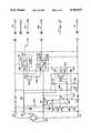
- FIG. 2is a detailed schematic of the preferred embodiment of the buffer-amplifier circuit in the new universal connector
- FIG. 3is a detailed schematic of a DC power supply circuit, for use as needed, in our new universal connector;
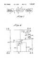
- FIG. 4is a detailed schematic of a current-regulating circuit, for use as needed in our new universal connector.
- FIG. 5is a detailed schematic of a circuit for eliminating an erroneous common-mode voltage from a transducer signal, for use as needed, in our new universal connector.
- FIG. 1provides a block diagram of our new system, including blood-pressure transducer 1 linked to blood-pressure monitor 7 by cables 2 and 6 and by our new universal connector 3.
- Connector 3includes buffer-amplifier circuit board 4 linked to circuit board 5, which includes either a DC power supply circuit, a current-regulating circuit, or a common-mode elimination circuit.
- FIG. 2provides a detailed schematic of the preferred embodiment of our buffer-amplifier circuit.
- This circuitdraws power from the blood-pressure monitoring means, and utilizes that power directly where the power is DC.
- Another circuitis used to modify and adapt the power if the power is sine wave or pulsed (see FIG. 3).
- the left side of the buffer-amplifier circuitis linked to the blood-pressure transducing means; the right side, to the blood-pressure monitoring means.
- positive and negative excitationpass from the monitoring means on paths 110 and 111 through contacts 6 and 12 to the other circuit in the connector means (described below) and return to the buffer-amplifier circuit, adapted as necessary, through contact pairs 5/11, 2/4, and 1/3.
- the excitation currentthen flows to the transducer along paths 112 and 113.
- Signals representative of blood pressurepass from the transducer means on paths 114 and 115 with their negative side on path 115, and their positive side, on path 114. These signals pass through protective resistors 116 and 117 to input rails 118 and 119 on amplifiers 120 and 121, respectively.
- the diffential gain through amplifiers 120 and 121is approximately one unless gain-setting resistors 122-124 are present. Normally, only an impedance level conversion takes place as the signals undergo buffering through amplifiers 120 and 121.
- a common transducer output impedanceis between 300 and 5,000 ohms; amplifier output impedance is in the range of about 1 to about 5 ohms.
- the buffer-amplifier circuitincludes means for removing offset errors in the signal voltage to the monitoring means. Adjustment of potentiometers 129 (on amplifier 121) and 130 (on amplifier 120) permit setting the output voltages of these amplifiers at the same level as their input voltages.
- Gain-setting resistors 122, 123 and 124permit accurate gain tailoring.
- Resistors 131, 132 and 133permit adjustment of amplifier bandwidth when programmable amplifiers are used.
- the buffer-amplifier circuit of FIG. 2also includes means for detecting a missing transducer or an open lead.
- Two resistor dividersare used to develop reference voltages.
- Resistors 134, 135 and 136develop two voltages referenced to the magnitude of the transducer excitation voltage.
- the voltage at junction 138 of resistors 134, 135 and 137is more than half the instantaneous transducer voltage; the voltage at junction 139 of resistors 135, 136 and 140 is less than half of the instantaneous transducer excitation voltage, and common-mode voltage from the transducer is about 50% of excitation voltage. Accordingly, the voltage at junction 141 of resistors 142 and 143 is about half the excitation voltage.
- the detection circuitryIn normal operation, the detection circuitry has little effect upon signal paths because resistors 137 and 140 are large compared with transducer output resistance, and because diodes 143-148 are reverse biased. If no transducer is present, however, resistors 137 and 140 are small compared to the input impedance of amplifiers 120 and 121. The resulting large reverse polarity signal at the blood-pressure monitor indicates the absence of a transducer.
- FIG. 3provides a detailed schematic of a DC power supply circuit. This circuit performs four functions.
- output resistors 201 and 202are matched or adjusted to the input impedance requirement of the monitoring means.
- Output signals from a buffer-amplifier circuit of FIG. 2appear at contacts 7 and 9 and return to the buffer-amplifier circuit through contacts 8 and 10.
- resistor network 203, 204 and 205provides this function.
- a calibration signalpasses through the buffer-amplifier circuit through contact 13.
- this circuitprovides sine wave phase correction through the network including potentiometer 206 and capacitors 207 and 208. Unbuffered signals from the transducer pass to sine wave phase correction through contacts 14 and 15.
- the fourth and most important function of the circuit in FIG. 3is conversion of sine wave or pulsed excitation signals to DC voltage suitable for operating the buffer-amplifier circuit.
- the components in the circuitare varied and tailored as needed.
- this circuitincludes capacitors 209, 210, 213 and 214 to hold voltage levels; diodes 211, 212, 215 and 216 for reverse biasing protection; resistor 217; and jumper wire 218. Omitted are jumper wires 219 and 220 and resistors 221 and 222.
- the negative excitation signal from the monitoring meansis used as a reference, and is connected to junction 223 via jumper wire 218.
- the upper and lower halves of this circuitthen function as two separate converters, with each functioning as a voltage doubler.
- the upper halfproduces a positive voltage; the lower half a negative voltage, with respect to the negative excitation signal.
- Capacitor valuesare appropriate to produce low-ripple DC voltage.
- the upper half of the circuitfunctions as follows. Assume that the excitation voltage is a sine wave from a transformer. Assume that the negative excitation voltage from the monitoring means is a reference voltage, and that all voltages in the power supply are defined with respect to this reference. Total excitation voltage is applied to each half of the circuit independently. As the negative half-cycle of the positive excitation signal from the monitoring means is applied to capacitor 213, current flows from the reference through diode 215 to charge the positive side of the capacitor 213 to approximately reference potential. The negative side of capacitor 213 is charged with a negative peak of the positive excitation signal. Therefore, capacitor 213 holds a voltage approximating the peak excitation voltage.
- capacitor 213As the positive excitation sine wave goes from a negative to a positive peak with respect to the reference, the voltage on both sides of capacitor 213 changes by the same amount.
- the negative side of capacitor 213changes from negative excitation peak to positive excitation peak.
- the positive sidechanges from the reference voltage to twice the positive excitation peak less the diode drop.
- the voltage on the positive side of capacitor 213also causes diode 211 to become forward biased. Current then flows into the positive side of capacitor 209.
- Capacitor 209is charged to a voltage that approximates double the positive excitation voltage peak minus two diode drops. Operation of the other half of the supply is the same, but polarity is reversed.
- the circuitry in FIG. 3is configured as follows. Capacitors 209 and 210, and diodes 211 and 212 remain in circuit with resistors 221 and 222 and jumper wires 220 and 219. Capacitors 213 and 214, diodes 215 and 216, resistor 217 and jumper wire 218 are omitted. With symmetrical waveforms, the excitation voltages are applied across both halves of the circuit in series. Where no pulse is present, both diodes 211 and 212 are back biased. When simultaneous pulses appear, these diodes conduct, and capacitors 209 and 210 receive charging current. The final voltage developed in capacitors 209 and 210 in series is approximately twice the pulse amplitude minus the drops across the diodes 211 and 212.
- Excitation voltagepasses from the circuitry of FIG. 2 to contacts 6 and 12, and returns to the buffer-amplifier circuit unaltered through contacts 1 and 3.
- DC powerreturns to the buffer-amplifer circuit through contacts 2, 4, 5 and 11.
- FIG. 4illustrates the preferred embodiment of the current-regulating circuit that provides three functions.
- output resistors 301 and 302serve the same functions as resistors 201 and 202 in the DC power circuit illustrated in FIG. 3.
- calibration resistors 303, 304 and 305serve the same function as calibration resistors 203, 204 and 205 in the circuitry of FIG. 3.
- this circuitprovides current regulation.
- the total excitation load current, on leads 6 and 12,passes through resistor 306.
- Amplifier 307samples the current at resistor 306, and varies amplifier output current through resistor 308, thus regulating current through resistor 306.
- Potentiometer 309 and resistor network 310/311permit current trimming.
- the reference voltage for amplifier 307 on negative rail 312is the excitation voltage on path 313 applied through resistor 314.
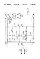
- FIG. 5provides a detailed schematic of a preferred embodiment for the common-mode eliminator circuit
- This circuithas three functions.
- resistors 401 and 402are matched to the impedance requirements of the monitor, and function as resistor 301/302 and 201/202 of FIGS. 3 and 4 do.
- calibration resistors 403, 404 and 405serve the same functions as the calibration resistors illustrated in FIGS. 3 and 4.
- the most important function of the circuitry in FIG. 5is to remove an erroneous common-mode voltage from the transducer signal and substitute a proper common-mode voltage.
- Amplifier 406 and its related componentsprovide the desired common-mode voltage, Potentiometer 407 is adjusted to obtain a voltage at the output 408 of amplifier 406 equal to half the excitation voltage This developed common-mode voltage then serves as the reference voltage for the differential amplifier circuit including amplifiers 409 and 410.
- Buffered transducer signalspass from the buffer-amplifier circuit of FIG. 2 through contacts 7 and 9.
- the signal through contact 7is applied to input resistors 410 and 411 along paths 412 and 413, respectively.
- the signal through contact 9is applied to input resistors 417 and 418 along paths 419 and 420, respectively Corrected signals at outputs 421 and 414 pass through output resistors 401 and 402, respectively, and then through contacts 8 and 10 to the buffer-amplifier circuit shown in FIG. 2.
- Potentiometers 415 and 416permit adjustment of the gain through amplifiers 409 410. Precise gain matching between two sides of the amplifiers is essential to maintain good common-mode rejection.
Landscapes
- Health & Medical Sciences (AREA)
- Life Sciences & Earth Sciences (AREA)
- Engineering & Computer Science (AREA)
- Power Engineering (AREA)
- Animal Behavior & Ethology (AREA)
- Heart & Thoracic Surgery (AREA)
- Physics & Mathematics (AREA)
- Veterinary Medicine (AREA)
- Biophysics (AREA)
- Pathology (AREA)
- Biomedical Technology (AREA)
- Public Health (AREA)
- Medical Informatics (AREA)
- Molecular Biology (AREA)
- Surgery (AREA)
- General Health & Medical Sciences (AREA)
- Cardiology (AREA)
- Physiology (AREA)
- Vascular Medicine (AREA)
- Measuring Pulse, Heart Rate, Blood Pressure Or Blood Flow (AREA)
Abstract
Description
Z=Generalized effort/,Generalized flow
Claims (6)
Priority Applications (1)
| Application Number | Priority Date | Filing Date | Title |
|---|---|---|---|
| US06/945,381US5193547A (en) | 1984-07-16 | 1986-12-22 | Universal connector means for transducer/monitor systems |
Applications Claiming Priority (3)
| Application Number | Priority Date | Filing Date | Title |
|---|---|---|---|
| US62989284A | 1984-07-16 | 1984-07-16 | |
| US83054686A | 1986-02-18 | 1986-02-18 | |
| US06/945,381US5193547A (en) | 1984-07-16 | 1986-12-22 | Universal connector means for transducer/monitor systems |
Related Parent Applications (1)
| Application Number | Title | Priority Date | Filing Date |
|---|---|---|---|
| US83054686AContinuation | 1984-07-16 | 1986-02-18 |
Publications (1)
| Publication Number | Publication Date |
|---|---|
| US5193547Atrue US5193547A (en) | 1993-03-16 |
Family
ID=27417483
Family Applications (1)
| Application Number | Title | Priority Date | Filing Date |
|---|---|---|---|
| US06/945,381Expired - LifetimeUS5193547A (en) | 1984-07-16 | 1986-12-22 | Universal connector means for transducer/monitor systems |
Country Status (1)
| Country | Link |
|---|---|
| US (1) | US5193547A (en) |
Cited By (16)
| Publication number | Priority date | Publication date | Assignee | Title |
|---|---|---|---|---|
| US5464017A (en)* | 1994-06-29 | 1995-11-07 | Juang; Jing-Song | LED display blood pressure meter |
| US5568815A (en)* | 1994-11-21 | 1996-10-29 | Becton Dickinson And Company | Self-powered interface circuit for use with a transducer sensor |
| USRE36000E (en)* | 1990-10-19 | 1998-12-22 | Nellcor Puritan Bennett Incorporated | Adhesive pulse oximeter sensor with reusable portion |
| WO1999059465A1 (en)* | 1998-05-21 | 1999-11-25 | Telecom Medical, Inc. | Patient monitoring apparatus |
| EP0973454A4 (en)* | 1998-02-10 | 2002-03-20 | Biosense Inc | Improved catheter calibration |
| US20050277671A1 (en)* | 2004-06-15 | 2005-12-15 | Pfizer Inc | Benzimidazolone carboxylic acid derivatives |
| US20050277672A1 (en)* | 2004-06-15 | 2005-12-15 | Pfizer Inc | Benzimidazolone carboxylic acid derivatives |
| US20060073728A1 (en)* | 2004-09-29 | 2006-04-06 | Zaiken Eliot J | Intrauterine pressure catheter interface cable system |
| US20060079792A1 (en)* | 2004-10-07 | 2006-04-13 | Finburgh Simon E | Compact apparatus and methods for non-invasively measuring hemodynamic parameters |
| US7317409B2 (en) | 2002-01-30 | 2008-01-08 | Tensys Medical, Inc. | Apparatus and method for interfacing time-variant signals |
| EP1221170A4 (en)* | 1999-09-08 | 2009-01-21 | Volcano Corp | Medical device having precision interconnect |
| US20100168547A1 (en)* | 2008-12-29 | 2010-07-01 | David Kendricks | Universal din leadwire system for use with ekg and ecg patient monitoring and event recording instruments |
| US20100198085A1 (en)* | 2007-02-27 | 2010-08-05 | Reinhold Knoll | Disposable Sensor Device and Monitoring System |
| US10206626B2 (en)* | 2014-07-31 | 2019-02-19 | Chuen Wei Lu | Biosignal measurement and transmission apparatus having simplified signal slot |
| US10285598B2 (en) | 2006-05-13 | 2019-05-14 | United States Gtm Medical Devices | Continuous positioning apparatus and methods |
| US10952675B2 (en) | 2007-10-12 | 2021-03-23 | Shangyi Medical Technology (Hangzhou) Co., Ltd | Apparatus and methods for non-invasively measuring a patient's arterial blood pressure |
Citations (13)
| Publication number | Priority date | Publication date | Assignee | Title |
|---|---|---|---|---|
| US3602215A (en)* | 1968-09-16 | 1971-08-31 | Honeywell Inc | Electrode failure detection device |
| US3721230A (en)* | 1970-11-23 | 1973-03-20 | Overton M Iii | High-gain monitor to determine electro-cerebral silence |
| US3868679A (en)* | 1973-10-09 | 1975-02-25 | Gen Electric | Blood pressure amplifier with zero balancing means |
| US3986495A (en)* | 1975-11-03 | 1976-10-19 | Hewlett-Packard Company | Optically excited diode current limiter |
| US4003370A (en)* | 1975-10-14 | 1977-01-18 | American Hospital Supply Corporation | Blood pressure monitor system and method |
| US4066974A (en)* | 1976-07-23 | 1978-01-03 | The Birtcher Corporation | Isolation amplifier |
| US4206762A (en)* | 1976-06-21 | 1980-06-10 | Cosman Eric R | Telemetric differential pressure sensing method |
| US4213348A (en)* | 1979-08-01 | 1980-07-22 | Medasonics, Inc. | Self-calibrating automatic zeroing strain gauge circuit |
| US4243044A (en)* | 1978-09-07 | 1981-01-06 | Hewlett-Packard Company | Coupling circuit with driven guard |
| US4297890A (en)* | 1979-06-07 | 1981-11-03 | Siemens Aktiengesellschaft | Pressure transducer |
| US4325382A (en)* | 1980-05-15 | 1982-04-20 | Memorial Hospital For Cancer And Allied Diseases | Process and apparatus for the real time adaptive filtering of catheter pressure measurements |
| US4598281A (en)* | 1982-12-15 | 1986-07-01 | Siemens Aktiengesellschaft | Electrical line interruption detection and alarm circuit |
| US4611601A (en)* | 1984-02-17 | 1986-09-16 | Transamerica Delaval Inc. | Disposable transducer systems |
- 1986
- 1986-12-22USUS06/945,381patent/US5193547A/ennot_activeExpired - Lifetime
Patent Citations (13)
| Publication number | Priority date | Publication date | Assignee | Title |
|---|---|---|---|---|
| US3602215A (en)* | 1968-09-16 | 1971-08-31 | Honeywell Inc | Electrode failure detection device |
| US3721230A (en)* | 1970-11-23 | 1973-03-20 | Overton M Iii | High-gain monitor to determine electro-cerebral silence |
| US3868679A (en)* | 1973-10-09 | 1975-02-25 | Gen Electric | Blood pressure amplifier with zero balancing means |
| US4003370A (en)* | 1975-10-14 | 1977-01-18 | American Hospital Supply Corporation | Blood pressure monitor system and method |
| US3986495A (en)* | 1975-11-03 | 1976-10-19 | Hewlett-Packard Company | Optically excited diode current limiter |
| US4206762A (en)* | 1976-06-21 | 1980-06-10 | Cosman Eric R | Telemetric differential pressure sensing method |
| US4066974A (en)* | 1976-07-23 | 1978-01-03 | The Birtcher Corporation | Isolation amplifier |
| US4243044A (en)* | 1978-09-07 | 1981-01-06 | Hewlett-Packard Company | Coupling circuit with driven guard |
| US4297890A (en)* | 1979-06-07 | 1981-11-03 | Siemens Aktiengesellschaft | Pressure transducer |
| US4213348A (en)* | 1979-08-01 | 1980-07-22 | Medasonics, Inc. | Self-calibrating automatic zeroing strain gauge circuit |
| US4325382A (en)* | 1980-05-15 | 1982-04-20 | Memorial Hospital For Cancer And Allied Diseases | Process and apparatus for the real time adaptive filtering of catheter pressure measurements |
| US4598281A (en)* | 1982-12-15 | 1986-07-01 | Siemens Aktiengesellschaft | Electrical line interruption detection and alarm circuit |
| US4611601A (en)* | 1984-02-17 | 1986-09-16 | Transamerica Delaval Inc. | Disposable transducer systems |
Non-Patent Citations (14)
| Title |
|---|
| "An Improved Systolic-Diastolic Pulse Separator", by Francis, Med. & Biol. Eng. vol. 12, No. 1 (Jan. 1974) pp. 105-108. |
| "Batteryless On-Demand-Sampling Active Radiosonde for Intracranial Pressure Measurement", by Macellari; Med. & Biol. Eng. & Comput vol. 14, No. 6 (Nov. 1981) pp. 686-694. |
| "Biomedical . . . Circuits", by Scott et al.; Med. & Biol. Eng.; vol. 14 #6; Nov. 1976, pp. 684-687. |
| "New Instrumentation Amplifiers for Electrical & Non Electrical Variables", by Sima Siemans Review XXXIX (1972) No. 2, pp. 75-77. |
| "Oscilloscope . . . Measurements", by Caldwell et al.; Med. & Biol. Eng. Jun. 1973, pp. 500-503. |
| "Versitile . . . Muscles", by Corinth; Elektroniks; vol. 23, #7; pp. 247-250 & 265. |
| 1980 Linear Databook by National Semiconductor, pp. 4 19 & 4 31.* |
| 1980 Linear Databook by National Semiconductor, pp. 4-19 & 4-31. |
| An Improved Systolic Diastolic Pulse Separator , by Francis, Med. & Biol. Eng. vol. 12, No. 1 (Jan. 1974) pp. 105 108.* |
| Batteryless On Demand Sampling Active Radiosonde for Intracranial Pressure Measurement , by Macellari; Med. & Biol. Eng. & Comput vol. 14, No. 6 (Nov. 1981) pp. 686 694.* |
| Biomedical . . . Circuits , by Scott et al.; Med. & Biol. Eng.; vol. 14 6; Nov. 1976, pp. 684 687.* |
| New Instrumentation Amplifiers for Electrical & Non Electrical Variables , by Sima Siemans Review XXXIX (1972) No. 2, pp. 75 77.* |
| Oscilloscope . . . Measurements , by Caldwell et al.; Med. & Biol. Eng. Jun. 1973, pp. 500 503.* |
| Versitile . . . Muscles , by Corinth; Elektroniks; vol. 23, 7; pp. 247 250 & 265.* |
Cited By (27)
| Publication number | Priority date | Publication date | Assignee | Title |
|---|---|---|---|---|
| USRE36000E (en)* | 1990-10-19 | 1998-12-22 | Nellcor Puritan Bennett Incorporated | Adhesive pulse oximeter sensor with reusable portion |
| US5464017A (en)* | 1994-06-29 | 1995-11-07 | Juang; Jing-Song | LED display blood pressure meter |
| US5568815A (en)* | 1994-11-21 | 1996-10-29 | Becton Dickinson And Company | Self-powered interface circuit for use with a transducer sensor |
| EP0973454A4 (en)* | 1998-02-10 | 2002-03-20 | Biosense Inc | Improved catheter calibration |
| WO1999059465A1 (en)* | 1998-05-21 | 1999-11-25 | Telecom Medical, Inc. | Patient monitoring apparatus |
| EP1221170A4 (en)* | 1999-09-08 | 2009-01-21 | Volcano Corp | Medical device having precision interconnect |
| US20080109199A1 (en)* | 2002-01-30 | 2008-05-08 | Conero Ronald S | Apparatus and method for interfacing time-variant signals |
| US10335081B2 (en)* | 2002-01-30 | 2019-07-02 | United States Gtm Medical Devices | Apparatus and method for interfacing time-variant signals |
| US20150133781A1 (en)* | 2002-01-30 | 2015-05-14 | Tensys Medical, Inc. | Apparatus and method for interfacing time-variant signals |
| US8818731B2 (en) | 2002-01-30 | 2014-08-26 | Tensys Medical, Inc. | Apparatus and method for interfacing time-variant signals |
| US7317409B2 (en) | 2002-01-30 | 2008-01-08 | Tensys Medical, Inc. | Apparatus and method for interfacing time-variant signals |
| US20050277672A1 (en)* | 2004-06-15 | 2005-12-15 | Pfizer Inc | Benzimidazolone carboxylic acid derivatives |
| US20080108660A1 (en)* | 2004-06-15 | 2008-05-08 | Pfizer Inc | Benzimidazolone Carboxylic Acid Derivatives |
| US20050277671A1 (en)* | 2004-06-15 | 2005-12-15 | Pfizer Inc | Benzimidazolone carboxylic acid derivatives |
| US20050277673A1 (en)* | 2004-06-15 | 2005-12-15 | Koji Ando | Benzimidazolone carboxylic acid derivatives |
| US8491503B2 (en)* | 2004-09-29 | 2013-07-23 | Covidien Lp | Intrauterine pressure catheter interface cable system |
| US20060073728A1 (en)* | 2004-09-29 | 2006-04-06 | Zaiken Eliot J | Intrauterine pressure catheter interface cable system |
| US7946994B2 (en) | 2004-10-07 | 2011-05-24 | Tensys Medical, Inc. | Compact apparatus and methods for non-invasively measuring hemodynamic parameters |
| US9247886B2 (en) | 2004-10-07 | 2016-02-02 | Tensys Medical, Inc. | Compact apparatus and methods for non-invasively measuring hemodynamic parameters |
| US20060079792A1 (en)* | 2004-10-07 | 2006-04-13 | Finburgh Simon E | Compact apparatus and methods for non-invasively measuring hemodynamic parameters |
| US10285598B2 (en) | 2006-05-13 | 2019-05-14 | United States Gtm Medical Devices | Continuous positioning apparatus and methods |
| EP2250960A1 (en)* | 2007-02-27 | 2010-11-17 | Edwards Lifesciences IPRM AG | Disposable sensor device and monitoring system |
| US20100198085A1 (en)* | 2007-02-27 | 2010-08-05 | Reinhold Knoll | Disposable Sensor Device and Monitoring System |
| US8920329B2 (en) | 2007-02-27 | 2014-12-30 | Edwards Lifesciences Iprm Ag | Disposable sensor device and monitoring system with trimming element |
| US10952675B2 (en) | 2007-10-12 | 2021-03-23 | Shangyi Medical Technology (Hangzhou) Co., Ltd | Apparatus and methods for non-invasively measuring a patient's arterial blood pressure |
| US20100168547A1 (en)* | 2008-12-29 | 2010-07-01 | David Kendricks | Universal din leadwire system for use with ekg and ecg patient monitoring and event recording instruments |
| US10206626B2 (en)* | 2014-07-31 | 2019-02-19 | Chuen Wei Lu | Biosignal measurement and transmission apparatus having simplified signal slot |
Similar Documents
| Publication | Publication Date | Title |
|---|---|---|
| US5193547A (en) | Universal connector means for transducer/monitor systems | |
| CA2159854C (en) | Self-powered interface circuit for use with a transducer sensor | |
| US8086300B2 (en) | ECG electrode contact quality measurement system | |
| US5427111A (en) | Receiver for differential signals with means for adjusting a floating ground state | |
| Spinelli et al. | AC-coupled front-end for biopotential measurements | |
| US4235242A (en) | Electronic circuit permitting simultaneous use of stimulating and monitoring equipment | |
| US4695955A (en) | Electronic device providing a universal interface between sensors and an acquisition and processing unit of the signals originating from said sensors | |
| US8089283B2 (en) | Apparatus and method for high-speed determination of bioelectric electrode impedances | |
| US5231990A (en) | Application specific integrated circuit for physiological monitoring | |
| US5329281A (en) | Analog to digital converter with autoranging offset | |
| US4993423A (en) | Method and apparatus for differential lead impedance comparison | |
| US20190029548A1 (en) | Impedance bootstrap circuit for an interface of a monitoring device | |
| JPH1028680A (en) | Device for monitoring measuring electrode and neutral electrode and lead wires therefor | |
| US20050203437A1 (en) | System and method for measuring bioelectric impedance in the presence of interference | |
| US5467090A (en) | Serial processing circuits with serial chaining | |
| Dobrev et al. | Simple two-electrode biosignal amplifier | |
| Pallás-Areny et al. | Composite instrumentation amplifier for biopotentials | |
| EP0132380A2 (en) | Connector means for transducer/monitor systems | |
| US3994286A (en) | Circuit arrangement for the processing of physiological measuring signals | |
| US4679568A (en) | Physiological potential preamplifier | |
| US11412971B2 (en) | ECG connector and ECG cable | |
| JP3176625B2 (en) | Physiological measurement signal processing circuit device | |
| RU2148377C1 (en) | Multichannel biopotential amplifier | |
| Fridlund et al. | Low‐Noise, Optically Isolated Electromyographic Preamplifier | |
| JPH10179531A (en) | Detecting circuit for detached electrode |
Legal Events
| Date | Code | Title | Description |
|---|---|---|---|
| AS | Assignment | Owner name:BAXTER TRAVENOL LABORATORIES, INC. A CORP. OF DE Free format text:MERGER;ASSIGNOR:AMERICAN HOSPITAL SUPPLY CORPORATION INTO;REEL/FRAME:004760/0345 Effective date:19870126 | |
| AS | Assignment | Owner name:BAXTER INTERNATIONAL INC. Free format text:CHANGE OF NAME;ASSIGNOR:BAXTER TRAVENOL LABORATORIES, INC., A CORP. OF DE;REEL/FRAME:005050/0870 Effective date:19880518 | |
| FEPP | Fee payment procedure | Free format text:PAYOR NUMBER ASSIGNED (ORIGINAL EVENT CODE: ASPN); ENTITY STATUS OF PATENT OWNER: LARGE ENTITY | |
| STCF | Information on status: patent grant | Free format text:PATENTED CASE | |
| FPAY | Fee payment | Year of fee payment:4 | |
| AS | Assignment | Owner name:EDWARDS LIFESCIENCES CORPORATION, CALIFORNIA Free format text:ASSIGNMENT OF ASSIGNORS INTEREST;ASSIGNOR:BAXTER INTERNATIONAL INC.;REEL/FRAME:010901/0274 Effective date:20000609 | |
| FPAY | Fee payment | Year of fee payment:8 | |
| FEPP | Fee payment procedure | Free format text:PAYER NUMBER DE-ASSIGNED (ORIGINAL EVENT CODE: RMPN); ENTITY STATUS OF PATENT OWNER: LARGE ENTITY Free format text:PAYOR NUMBER ASSIGNED (ORIGINAL EVENT CODE: ASPN); ENTITY STATUS OF PATENT OWNER: LARGE ENTITY | |
| FPAY | Fee payment | Year of fee payment:12 |