US5193525A - Antiglare tip in a sheath for an endoscope - Google Patents
Antiglare tip in a sheath for an endoscopeDownload PDFInfo
- Publication number
- US5193525A US5193525AUS07/620,488US62048890AUS5193525AUS 5193525 AUS5193525 AUS 5193525AUS 62048890 AUS62048890 AUS 62048890AUS 5193525 AUS5193525 AUS 5193525A
- Authority
- US
- United States
- Prior art keywords
- tip
- endoscope
- image viewer
- light source
- sheath
- Prior art date
- Legal status (The legal status is an assumption and is not a legal conclusion. Google has not performed a legal analysis and makes no representation as to the accuracy of the status listed.)
- Expired - Lifetime
Links
- 230000004313glareEffects0.000claimsabstractdescription29
- 230000013011matingEffects0.000claimsabstractdescription11
- 238000003780insertionMethods0.000claimsabstractdescription9
- 230000037431insertionEffects0.000claimsabstractdescription9
- 238000000034methodMethods0.000claimsdescription21
- XLYOFNOQVPJJNP-UHFFFAOYSA-NwaterSubstancesOXLYOFNOQVPJJNP-UHFFFAOYSA-N0.000claimsdescription11
- 230000004888barrier functionEffects0.000claimsdescription8
- 230000000903blocking effectEffects0.000claimsdescription7
- 230000008878couplingEffects0.000claimsdescription3
- 238000010168coupling processMethods0.000claimsdescription3
- 238000005859coupling reactionMethods0.000claimsdescription3
- 238000001746injection mouldingMethods0.000claimsdescription3
- 238000003754machiningMethods0.000claimsdescription2
- 239000007921spraySubstances0.000claimsdescription2
- 230000005540biological transmissionEffects0.000claims1
- 230000001681protective effectEffects0.000claims1
- 238000001574biopsyMethods0.000description25
- 238000004519manufacturing processMethods0.000description8
- 239000000463materialSubstances0.000description8
- 230000008901benefitEffects0.000description6
- 238000011109contaminationMethods0.000description6
- 239000012780transparent materialSubstances0.000description6
- 238000004140cleaningMethods0.000description5
- 239000000853adhesiveSubstances0.000description3
- 230000001070adhesive effectEffects0.000description3
- 238000005553drillingMethods0.000description3
- 230000001154acute effectEffects0.000description2
- 230000001427coherent effectEffects0.000description2
- 230000004438eyesightEffects0.000description2
- 239000000835fiberSubstances0.000description2
- 230000007246mechanismEffects0.000description2
- 230000002093peripheral effectEffects0.000description2
- 238000004080punchingMethods0.000description2
- 238000003892spreadingMethods0.000description2
- 230000007480spreadingEffects0.000description2
- 238000004026adhesive bondingMethods0.000description1
- 210000004204blood vesselAnatomy0.000description1
- 210000000621bronchiAnatomy0.000description1
- 210000001072colonAnatomy0.000description1
- 238000004891communicationMethods0.000description1
- 238000010276constructionMethods0.000description1
- 238000007796conventional methodMethods0.000description1
- 230000002498deadly effectEffects0.000description1
- 230000007423decreaseEffects0.000description1
- 238000013461designMethods0.000description1
- 238000003745diagnosisMethods0.000description1
- 230000009365direct transmissionEffects0.000description1
- 230000009977dual effectEffects0.000description1
- 210000001198duodenumAnatomy0.000description1
- 210000003238esophagusAnatomy0.000description1
- 239000012530fluidSubstances0.000description1
- 125000001475halogen functional groupChemical group0.000description1
- 238000010438heat treatmentMethods0.000description1
- 238000005286illuminationMethods0.000description1
- 238000002347injectionMethods0.000description1
- 239000007924injectionSubstances0.000description1
- 208000003243intestinal obstructionDiseases0.000description1
- 238000002955isolationMethods0.000description1
- 230000003287optical effectEffects0.000description1
- 210000003200peritoneal cavityAnatomy0.000description1
- 238000004023plastic weldingMethods0.000description1
- 230000002265preventionEffects0.000description1
- 230000002685pulmonary effectEffects0.000description1
- 230000005855radiationEffects0.000description1
- 210000000664rectumAnatomy0.000description1
- 210000001599sigmoid colonAnatomy0.000description1
- 239000007787solidSubstances0.000description1
- 210000002784stomachAnatomy0.000description1
- 238000001356surgical procedureMethods0.000description1
- 239000013306transparent fiberSubstances0.000description1
- 238000002604ultrasonographyMethods0.000description1
Images


Classifications
- A—HUMAN NECESSITIES
- A61—MEDICAL OR VETERINARY SCIENCE; HYGIENE
- A61B—DIAGNOSIS; SURGERY; IDENTIFICATION
- A61B1/00—Instruments for performing medical examinations of the interior of cavities or tubes of the body by visual or photographical inspection, e.g. endoscopes; Illuminating arrangements therefor
- A61B1/00163—Optical arrangements
- A61B1/00174—Optical arrangements characterised by the viewing angles
- A—HUMAN NECESSITIES
- A61—MEDICAL OR VETERINARY SCIENCE; HYGIENE
- A61B—DIAGNOSIS; SURGERY; IDENTIFICATION
- A61B1/00—Instruments for performing medical examinations of the interior of cavities or tubes of the body by visual or photographical inspection, e.g. endoscopes; Illuminating arrangements therefor
- A61B1/00064—Constructional details of the endoscope body
- A61B1/00071—Insertion part of the endoscope body
- A61B1/0008—Insertion part of the endoscope body characterised by distal tip features
- A61B1/00096—Optical elements
- A—HUMAN NECESSITIES
- A61—MEDICAL OR VETERINARY SCIENCE; HYGIENE
- A61B—DIAGNOSIS; SURGERY; IDENTIFICATION
- A61B1/00—Instruments for performing medical examinations of the interior of cavities or tubes of the body by visual or photographical inspection, e.g. endoscopes; Illuminating arrangements therefor
- A61B1/00064—Constructional details of the endoscope body
- A61B1/00071—Insertion part of the endoscope body
- A61B1/0008—Insertion part of the endoscope body characterised by distal tip features
- A61B1/00101—Insertion part of the endoscope body characterised by distal tip features the distal tip features being detachable
- A—HUMAN NECESSITIES
- A61—MEDICAL OR VETERINARY SCIENCE; HYGIENE
- A61B—DIAGNOSIS; SURGERY; IDENTIFICATION
- A61B1/00—Instruments for performing medical examinations of the interior of cavities or tubes of the body by visual or photographical inspection, e.g. endoscopes; Illuminating arrangements therefor
- A61B1/00064—Constructional details of the endoscope body
- A61B1/0011—Manufacturing of endoscope parts
- A—HUMAN NECESSITIES
- A61—MEDICAL OR VETERINARY SCIENCE; HYGIENE
- A61B—DIAGNOSIS; SURGERY; IDENTIFICATION
- A61B1/00—Instruments for performing medical examinations of the interior of cavities or tubes of the body by visual or photographical inspection, e.g. endoscopes; Illuminating arrangements therefor
- A61B1/00142—Instruments for performing medical examinations of the interior of cavities or tubes of the body by visual or photographical inspection, e.g. endoscopes; Illuminating arrangements therefor with means for preventing contamination, e.g. by using a sanitary sheath
- Y—GENERAL TAGGING OF NEW TECHNOLOGICAL DEVELOPMENTS; GENERAL TAGGING OF CROSS-SECTIONAL TECHNOLOGIES SPANNING OVER SEVERAL SECTIONS OF THE IPC; TECHNICAL SUBJECTS COVERED BY FORMER USPC CROSS-REFERENCE ART COLLECTIONS [XRACs] AND DIGESTS
- Y10—TECHNICAL SUBJECTS COVERED BY FORMER USPC
- Y10S—TECHNICAL SUBJECTS COVERED BY FORMER USPC CROSS-REFERENCE ART COLLECTIONS [XRACs] AND DIGESTS
- Y10S600/00—Surgery
- Y10S600/92—Method of making endoscopes
Definitions
- This inventionrelates to endoscopes, and more particularly, to an antiglare tip for ensuring that only light reflected from objects external to the endoscope enters the image viewer.
- Endoscopesare presently used in the medical and industrial fields. Within the medical field, endoscopes have many uses. Frequently the endoscope design and name are based on its use. For example, there are upper endoscopes for examination of the esophagus, stomach and duodenum, cystoscopes for examining the bladder, colonoscopes for examining the colon, angioscopes for examining the blood vessels and heart, bronchoscopes for examining the bronchi, laparoscopes for examining the peritoneal cavity, arthroscopes for examining joint spaces, and sigmoidoscopes for examining the rectum and sigmoid colon.
- Industrial endoscopessometimes called boroscopes, may be used for examining contaminated or inaccessible locations, such as the interior of large vessels used for nuclear reactors and similar environments.
- Endoscopesextend a user's vision and access into places the user cannot enter directly. For example, cavities within the human body are generally sufficiently small to prevent direct vision and access without surgery. Similarly, a person cannot enter the inside of a nuclear reactor without receiving deadly doses of radiation. Accordingly, endoscopes are provided for examining and probing environments which a person may not enter directly.
- endoscopesare generally provided with an image viewer and one or more light sources.
- the light sourcesemit a bright light to illuminate external objects so that they can be viewed through the image viewer.
- the useris then able to perform the desired task, such as medical diagnosis, treatment, or the like.
- Glareis created by the transparent window in many different ways.
- Light emitting from the light guidemay reflect from an inside surface of the window and into the image viewer.
- lightmay reflect within the window itself and enter the image viewer, creating a ghost image or glare. This glare interferes with the ability of the user to view a coherent and sharp image.
- only light reflected from objects external to the endoscopeshould be permitted to enter the image viewer, so that the view provided to the user represents a true image.
- Japanese Utility Publication No. 63-33209to Yamamoto and assigned to Olympus Optical, describes a protrusion extending from the end of the endoscope to hold the sheath away from contact with the light-emitting and image viewer lenses. Glare is not prevented because light entering the sheath from the light sources may be reflected internally to the image viewer, creating a ghost image or glare.
- U.S. Pat. No. 4,794,911, to Okadadescribes a cap mounted on the distal end of an endoscope. The light sources are flush with the end of the endoscope.
- Glareoccurs because light is reflected from the inside surface of the cap and enters the image viewer. Direct light from the light source enters the image viewer, preventing a clear view of external objects.
- One reason that sheaths have not been widely used on endoscopesis because of the difficulty of obtaining an image which contains only light reflected from external objects and is free from unwanted glare.
- an interfitting regionbetween a sheath tip and an endoscope, positioned between the light source and the image viewer, to prevent glare in the image viewer.
- the interfitting regionincludes a projection from the endoscope mating with a recess in the sheath tip. Alternatively, the projection may extend from the sheath tip and mate with a recess in the endoscope.
- the interfitting regionincludes a light-blocking member to ensure that only light reflected from objects external to the endoscope may enter the image viewer.
- an endoscope insertion tubehas opaque projections around the light source and image viewer.
- the sheath tipincludes opaque recesses aligned for mating with the projection from the endoscope.
- the projections extending into the sheath tip and mating with respective recesses in the tipensures that light cannot pass directly from the light source to the image viewer.
- the biopsy channelextends from an aperture in a raised step of the tip. Water and air channels extend perpendicular from the raised step and are aligned with the image viewer to ensure adequate cleaning.
- the tipis preferably manufactured by forming apertures within a single-piece opaque member and mounting lenses in the apertures.
- the lensesare mounted flush with the top surface of the single-piece opaque member to provide a flat surface which is easy to keep clean.
- the aperturesform the recesses that mate with the projections of the endoscope.
- the endoscope tipmay thus be easily mass-produced and reliably manufactured using mechanized techniques.
- an interfitting regionincludes a light-blocking member that extends between the light source and the image viewer to ensure that no light passes directly from the light source to the image viewer.
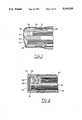
- FIG. 1.is a cross-sectional view of a prior art glare prevention device for a sheathed endoscope.
- FIG. 2is a cross-sectional view of a prior art sheath tip.
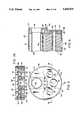
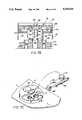
- FIG. 3is an isometric view of an endoscope having a sheath extending around the insertion tube.
- FIG. 4is an exploded isometric view of the endoscope and sheath tip combination of FIG. 3.
- FIG. 5is an end plan view of a sheath tip and endoscope combination of FIG. 3.
- FIG. 6is a cross-sectional view taken along lines 6--6 of FIG. 5.
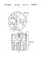
- FIG. 7Ais a cross-sectional view taken along lines 7A--7A of FIG. 5.
- FIG. 7Bis an exploded cross-sectional view of an alternative embodiment of a sheath tip and endoscope combination.
- FIG. 7Cis an isometric view of a mechanical apparatus useful in one step of manufacturing the tip.
- FIG. 8is an end plan view of an alternative embodiment of a sheath tip and endoscope combination having an opaque projection extending into the endoscope.
- FIG. 9is an exploded cross-sectional view taken along lines 9--9 of FIG. 8.
- FIG. 10is an end plan view of an alternative embodiment of a sheath tip and endoscope combination having a projection from the endoscope extending into the sheath tip.
- FIG. 11is an exploded cross-sectional view taken along lines 11--11 of FIG. 10.
- FIG. 12is an enlarged view of a necked down portion for preventing glare in the tip of an endoscope.
- FIG. 13is an end plan view of an alternative embodiment of a sheath tip and endoscope combination having the light source coupled as an integral portion of the tip and the image viewer flush with the end.
- FIG. 14is an exploded cross-sectional view taken along lines 14--14 of FIG. 13.
- FIG. 15is an end plan view of a sheath tip and endoscope combination having a raised step between the light source and the image viewer.
- FIG. 16is an exploded cross-sectional view taken along lines 16--16 of FIG. 15.
- FIG. 17is an end plan view of a sheath tip and endoscope combination having a projection from the endoscope into the tip.
- FIG. 18is an exploded cross-sectional view taken along lines 18--18 of FIG. 17.
- FIG. 19is an exploded cross-sectional view of a sheath tip and endoscope combination having a locking member to retain the sheath on the endoscope.
- FIG. 20is an end plan view of an alternative embodiment of the light source combined with the biopsy tube.
- FIG. 21is an isometric view of a video viewing endoscope having projections around the light source and the image viewer.
- FIG. 1illustrates a prior art structure from Japanese Utility Publication No. 63-33209 for reducing glare caused by an endoscope sheath.
- a prior art endoscope 50includes a light source 52 and an image viewer 54. Lenses 56 and 58 are positioned over the light source 52 and the image viewer 54, respectively.
- a sheath 60extends over the end of the endoscope 50, covering the lenses 56 and 58.
- a band 61holds the sheath 60 on the endoscope 50.
- An opaque protrusion 62extends between the light source 52 and the image viewer 54. The opaque protrusion 62 is designed to prevent the direct transmission of light to the image viewer 54 from the light source 52.
- opaque protrusion 62does not effectively prevent light from passing directly to the image viewer 54 from the light source 52, and glare results.
- the sheath 60may become slightly separated from the opaque protrusion 62, leaving a gap between the sheath 60 and the opaque protrusion 62.
- Light exiting from lens 56reflects from the inside surface of the sheath 60, passes through the gap, and enters the lens 58, causing significant glare.
- Internal reflections within the sheath 60 itselfare a second source of glare. Some of the light entering the inside surface of the sheath 60 is also reflected internally from the outside surface 63 of sheath 60.
- This reflected lightremains within the sheath layer stretched over the end of the endoscope, and is reflected to the image viewer 54.
- This internally reflected light within the sheath 60creates a ghost image, halo, or glare that interferes with the user viewing a coherent image.
- a further problemis that the band 61 may be pulled off and lost within a human body, causing additional problems such as intestinal obstruction or pulmonary aspiration. Accordingly, this prior art fails to solve the problem of glare caused by light entering the image viewer 54 directly from the light guide 52, without first being reflected by external objects.
- FIG. 2illustrates a different prior art endoscope 50 having a tip 59, as shown in U.S. Pat. No. 4,794,911.
- the endoscope 50includes a light guide 52 and an image viewer 54, similar to that shown in the prior art of FIG. 1.
- a light source lens 56 and a viewer lens 58are mounted flush with the surface of the endoscope 50.
- Tip lenses 64 and 66are mounted flush with an inside surface of the tip 59.
- Some of the light exiting from light source 52reflects from the inside surface 65 of the lens 64, creating glare in image viewer 54.
- a second problemis that debris may enter the recess around the lenses and be difficult to remove, further blocking a clear view.
- FIG. 3illustrates the inventive antiglare tip 70 on a sheath 60 covering an endoscope 50.
- the endoscope 50 and sheath 60may be of the type described in U.S. Pat. No. 4,646,722 or any other suitable prior art sheath and endoscope combination, such as those shown in FIGS. 1 and 2.
- the structure at the distal end 72 of the endoscopeis configured to cooperate with the tip 70 of the sheath 60 to provide an interfitting region that prevents glare in the image viewer, as explained in more detail herein.
- FIG. 4illustrates a sheath 60 having the inventive tip 70 positioned for extending over the distal end 72 of endoscope 50.
- the tip 70includes an outside surface 74 having lenses 76 located therein and positioned to mate with corresponding light sources and an image viewer in end 72 of endoscope 50.
- the lenses 76may be any suitable light transparent member, including flat lenses, concave, convex, light-gathering lenses, or of other types generally known in the art, such as those shown in FIGS. 1 and 2.
- the lenses 76are mounted with their edges flush with outside surface 74, providing a smooth and continuous outside surface across tip 70.
- lenses 76are concave or convex, the edges are mounted flush with the outside surface 74, and any deviations from the flat surface 74 occur in the smooth continuous shape of the lens. This precludes tip surface recesses, or sharp protrusions, which can accommodate debris, are difficult to wash off, and can interfere with the image.
- a raised step 77includes an aperture 78 for aligning with the suction or biopsy channel of the endoscope.
- the aperture 78 and interface of the biopsy channel of the endoscopeis made by any conventional method known in the art, such as that described in U.S. Pat. No. 4,947,827, incorporated herein by reference and having the same inventive entity. Having the biopsy channel in a raised step on the tip 70 is not required, and this portion may be flat with surface 74; however, the raised section facilitates cleaning of the lenses with wash and air sprays, as explained later.
- the end 72 of endoscope 50includes a flat surface 80 and projecting portions 82, 84, and 86.
- the projecting portionsextend above the flat surface 80 of end 72 and surround the light sources and image viewer.
- a groove 81is provided for receiving a removable biopsy tube and air and water tubes as is known in the art from those patents incorporated by reference.
- the sheath 60is placed over the insertion tube of endoscope 50 and the tip 70 is brought into abutting contact with end 72.
- the userinserts the sheath endoscope, having the antiglare tip 72 thereon, into the patient's body under examination, or, for an industrial endoscope, into the vessel to be examined.
- the endoscopeis removed from the patient, the sheath 60, together with tip 70, is removed from the endoscope 50 and disposed of in the appropriate manner to prevent the spread of contamination from the sheath.
- FIGS. 5, 6, 7A, 7B and 7Cprovide an enlarged and detailed view of the inventive tip 70 and end 72 of endoscope 50.
- An interfitting region 81 of the sheath tip 70 and the endoscope 50includes light-blocking members positioned between the light source and the image viewer to prevent glare.
- Opaque projections 82, 84, and 86 of the endoscope 50mate with opaque recesses 95 of the tip 70 to form the interfitting region 81 on an inside surface of the tip 70.
- the tip 70includes a single-piece opaque member 88 having a flat outside surface 74 and a raised step 77.
- the lenses 76are positioned in apertures within the single-piece opaque member 88.
- a holeis formed by any acceptable method, such as drilling, punching, injection molding having the appropriate hole therein, or the like, to provide the apertures.
- the aperturesare countersunk, that is, contain an enlarged diameter portion having a shoulder 90. The depth of the enlarged diameter portion providing shoulder 90 is selected to equal the height of the edges of lens 76, so that when the lens 76 abuts against the shoulder 90, the top surface, at the edges, is flush with flat outside surface 74 of the tip 70.
- Having the aperture countersunk with the shoulder 90increases manufacturing speed by permitting the lens 76 to be press fit into the aperture until it solidly abuts the shoulder 90 while ensuring the proper mounting of lens 76.
- the lens 76may be secured in the aperture by any suitable technique, such as press fitting, gluing at the edges, or the like.
- the opaque member 88extends in an interfitting relationship between the light source and the image viewer to ensure that all possible paths of light are blocked. Even if the end piece 88 is not in abutting contact or correct alignment with the end 72, reflected light can be prevented from entering the image viewer 54 because the projections 82, 84, and 86 extend in a direction perpendicular to the direction of light travel between the light guide 52 and the image viewer 54.
- the sheath 60may stretch, twist, or be distorted during use, especially within the inside of a patient separating the opaque member 88 from the endoscope end 72.
- the opaque member 88extends longitudinally towards the endoscope in a direction perpendicular to the path the light must travel to create the unwanted glare.
- the opaque member 88surrounds either the light guide 52 or image viewer 54, or both, to block all light from entering the image viewer 54 which is not reflected from objects outside of the endoscope.
- the raised step 77is configured to cooperate with groove 81 of endoscope 50, having a biopsy channel 83 therein.
- the raised step 77includes a large aperture 78 coupled to the biopsy or suction channel 83 of the endoscope.
- the raised step 77also includes one or more through channels 92 having a high-pressure nozzle 94.
- the channels 92are in fluid communication with tubes supplied by the endoscope to provide water and air at the outside of the tip.
- a water supply tube 93is coupled to channel 92 having a nozzle 94 formed therein.
- the nozzle 94provides a wash jet at the appropriate pressure to wash the outside surface of lens 76.
- an air supply tube 97(see FIG. 7B) is coupled to an air nozzle 96 to provide an air jet at the appropriate pressure.
- the sheath 60 and tip 70completely seal the endoscope 50 from the outside environment and possible contamination.
- the sheath 60is coupled to the tip 70 and, in one embodiment, extends between the water tubing 93, air tubing 97, biopsy channel 83 and the endoscope 50 (see FIG. 7B).
- the sheathsurrounds the endoscope but does not extend around the tubings 93 and 97, the tubings being completely sealed to contain contamination.
- the sheath 60also completely surrounds the endoscope 50.
- the sheath 60, biopsy channel 83, water tubing 93, and air tubing 97are coupled to the tip 70 by any suitable method, including adhesives, plastic welding, heat fusing, or other suitable technique that forms a contamination barrier.
- the nozzles 94 and 96are an integral part of the single-piece opaque member 88.
- the nozzles 94 and 96extend perpendicular to the flat outside surface 74 of the tip 70.
- the nozzles 94 and 96are formed by drilling into the stepped portion 77 at the desired height to provide the appropriate diameter for a nozzle for the wash and air channels.
- the nozzles 94 and 96are drilled to a sufficient depth to mate with the recess extending in from the inside surface of the opaque member 88 to form the channel 92. Having the wash nozzle 94 and air nozzle 96 extend perpendicular to and point across one or more lenses 76 provides the advantage that the lens may be completely and reliably cleaned as needed.
- the raised step 77provides a convenient location for integrally mounting the nozzles adjacent the lenses 76, one of the advantages of raised step 77. Having the nozzles 94 mounted in the raised step 77 also increases their reliability because they are recessed and protected by the raised step 77, thus preventing them from being broken or damaged when the endoscope is in use. Patient comfort is also enhanced because the raised step 70 may be constructed in a smooth, rounded shape as shown at corners 101 and does not have external extending nozzles, which have the possibility of irritating an inside surface of the patient's body.
- the tip 70may be constructed by any suitable method.
- a preferred material for the single-piece opaque member 88is a black plastic disk.
- the diskis machined to provide flat outside surface 74, raised step 77, and the appropriate apertures and channels, as described.
- the apertures and nozzlesare formed by common techniques, such as drilling, punching, or the like.
- the opaque member 88may be injection-molded having the desired shape and thus be mass-produced having the raised step 77, flat surface 74, and the appropriate apertures preformed in the injection mold. Any other suitable technique for providing the tip 70 of suitable opaque material having the structure as shown, may also be used.
- interfitting region 81includes projections 82, 84, and 86 mating with single-piece member 88, seen in cross section.
- the projections 82, 84, and 86are opaque members that extend above the surface 80 of the endoscope. These projections mate with the recesses 95 of the tip 72, as previously explained, to form the interfitting region 81 that prevents light from passing from the light source 52 to the image viewer 54.
- the apertureforms a recess 95, as best seen in FIGS. 7A and 7B.
- the single-piece opaque member 88forms the sidewalls of the recess 95, and the lens 76 is sealed into the opaque member 88 to ensure that contamination and matter cannot pass to the endoscope 50 from outside of the sheath 60.
- the depth of the sidewalls of recess 95are selected based on the height of projections 82, 84 and 86 to ensure that the inside surface of opaque member 88 abuts against the flat surface 80 of end 72 prior to the lens 76 striking any projection. Having the opaque member 88 abut against the surface 80 ensures that all light exiting from the light guide 52 is blocked by the tip except that portion exiting from the appropriate lens 76 and also prevents the lens from being dislodged by the endoscope.
- FIG. 7Billustrates an alternative embodiment having a locking snap mechanism to hold the tip 70 onto the endoscope 50.
- the tip 70includes a protrusion 170 extending from the inside surface of a shoulder 172.
- the endoscope 50includes an indent 176 within a recess 174 positioned to mate with the protrusion 170 and shoulder 172, respectively.
- the shoulder 172deflects slightly to permit the protrusion 170 to slide along an inside surface of the recess 174 and snap into the indent 176.
- the shoulder 172 and protrusion 170are sufficiently resilient to grip the endoscope 50 and hold the tip 70 in position on the endoscope throughout the medical procedure.
- the shoulder 172preferably extends for at least a short distance circumferentially around the tip 70 so that if the tip twists, the protrusion 170 remains within the indent 176. In one embodiment, the shoulder 172 extends completely around the tip 70 to form a ring to ensure that the tip 70 does not separate from the endoscope 50 unless it is intentionally removed at the conclusion of a procedure.
- FIG. 7Cillustrates a mechanical arm 180 for inserting lenses 76 into the tip 70 during one step of the manufacturing process.
- a lens 76is held in cup 186.
- the lens 76is held by any suitable mechanism, such as a suction cup, as shown, fingers gripping at its edges or the like. Adhesive may be applied to the edges of the lens 76 prior to inserting it into the tip 70.
- the arm 180pivots about pivot 184 under control of actuator 182. As the arm pivots downward, the lens 76 is inserted into the tip 70 and press fit into solid abutment with shoulder 90 to form a flush top outside surface, as previously described.
- the arm 180then pivots back to the initial position, receives a new lens 76, and pivots forward to place the new lens 76 into the correct aperture 91 of the tip 70.
- the tip 70 and/or the arm 180are appropriately moved between insertion operations to position the proper aperture 91 in alignment to receive the lens using mechanized assembly techniques known in the art.
- the next tip 70is then advanced into position for the inserting of lenses 76.
- the lenses 76may be manually mounted using similar techniques.
- the lens 76may be held in the hand of a worker, adhesive applied, if desired, and pressed, by hand, into the appropriate aperture 91 until it abuts against shoulder 90.
- the tip 70may thus be manually manufactured if desired. In both embodiments of manufacture, mechanical and manual, the lenses 76 form a tight seal with the tip 70 to ensure that contaminated matter may not seep through the tip and contact the endoscope 50.
- the appropriate lenses, waveguides, and fiberoptic membersmay be used as part of the light source and image viewer as is well known in the prior art.
- the terms "light source” and "image viewer”are broadly defined to include their full assembly within an endoscope.
- the light sourceincludes not only the source of the light and light guide if used, but also the lenses and windows within the endoscope that facilitate the illumination of objects extending to the endoscope.
- the image viewerincludes the CCD imager or fiberoptic cable as well as the light collecting and focusing lenses, windows, and the like that provide an image, or signal representing an image, from the distal end of the endoscope to a proximal end of the endoscope.
- the technical advantages of the antiglare tip and endoscope combinationare that light is prevented from passing from the light source directly to the image viewer by a recess of the endoscope tip 70 mating with a projection extending from the endoscope.
- Opaque member 88 within the tipitself blocks light, preventing it from spreading directly from the light source 52 to the image viewer 54 through the lens material.
- the opaque member 88solidly abuts against the end of the endoscope to ensure that light reflected from an inside surface of the lens 76 is blocked and may not enter the image viewer 54.
- the opaque blocking member 88from a single piece. Having the bores for the lenses 76 countersunk increases the manufacturing speed and ensures that the edge surfaces reliably register with the upper surface 74 to provide a smooth, flat interface between the edge of the lens and the surface 74.
- FIGS. 8 and 9illustrate an alternative embodiment of an interfitting region 81 having a projection 100 mating with recess 102 in the end of endoscope 50.
- the majority of the tip 70is clear, being formed of a transparent material. Lenses or, alternatively, a plastic transparent member functioning merely as a clear cover may be used as tip 70.
- the projection 100extends between the light source 52 and the image viewer 54, providing an opaque barrier.
- the opaque projection 100extends completely through the tip 70 from an outside surface 106 to an inside surface 104, and then projects beyond the surface 104.
- the position and shape of opaque barrier 100ensures that light cannot travel through the lens material itself from the light source 52 to the image viewer 54.
- the projection 100extends longitudinally into the recess 102 within the endoscope 50, ensuring that any light reflected from the inside surface 104 of the tip 70 is blocked and cannot be received by the image viewer 54.
- the opaque projection 100extends perpendicular to the direction light must travel to pass directly from the light source 52 to the image viewer 54. Even if the tip 70 separates slightly from the surface 72, light is still blocked by the longitudinally-extending opaque member 100.
- An aperture 78is provided in the tip 70 for the biopsy channel as previously described with respect to FIGS. 3-7 or using some other structure which may be available in the art.
- the entire surface of the tip 70is flat, the biopsy aperture 78 being flush with the surface of the tip and not in a raised step.
- the wash and air channelsextend from small nozzles 105 and 107, respectively, adjacent the biopsy tubing, according to a manner known in the art to provide the needed wash and dry functions.
- FIGS. 8 and 9may also be constructed from a single-piece opaque disk 88 by mounting lenses 76 at the appropriate locations and having multiple projections 100, similar to that shown and described in FIGS. 3-7. If a single-piece disk 8B is used, the lenses are mounted flush with a top surface. Recesses are formed in the endoscope end 72 in place of one or more of the projections 82, 84, and 86 so that a projection 100 extending from the tip 70 mates with and enters into a corresponding recess of endoscope end 72. The projections and recesses of the tip and the end 72 are reversed from those shown in FIGS. 3-7.
- FIGS. 10 and 11illustrate an alternative embodiment of the interfitting region 81 having the image viewer extending from the endoscope 50 and the light source 52 flush with the surface 80 of the endoscope 50.
- the tip 70is comprised entirely of transparent material, the shape of the tip being selected to prevent light from spreading from the light guide 52 to the image viewer 54, rather than using an opaque light barrier.
- the tip 70includes an opaque recess 108 positioned to mate with projection 110 surrounding the image viewer 54 and extending from the top surface 80 of the endoscope 50.
- the tip 70includes a plurality of sharp turns which trap the light and prevent it from extending through the tip from the light source 52 to the image viewer 54.
- a first angle 112is positioned at the surface of the endoscope, and a second angle 114 is positioned at the top of the recess 108. Any light reflecting within the tip 70 must pass through these two angles, in series, before it reaches the image viewer 54.
- the shape and position of the anglesare selected to trap all light, such that no light is able to successfully reflect internally within the lens material through the two in-series, angled portions.
- the lens 70narrows from the first thickness at point 116 adjacent the light source to a second, narrower thickness at point 118 to further restrict the passage of light within the lens material. This necked-down portion prior to acute angle also traps many internal refractions of light within the tip 70. Reflections from an inside surface of the tip 70 are blocked by the projection 110, providing complete light isolation between the light source member 52 and the image viewer 54.
- the distance between the light source 52 and the upper edge of tip 70 over projection 110is selected to ensure that light does not reenter the tip directly from the light source.
- the lightspreads out of light source 52 along a path 119 at a selected angle ⁇ .
- the angle ⁇varies with the lens 76, but will generally be in the range of 120 degrees. If the projection 110 is too close to the light source, light will enter the tip without first being reflected by an external object.
- the top of the tip 70 over the projection 110is spaced and positioned to ensure that the light does not directly enter the tip from the light source and cause glare.
- Narrow-necked portions 120are formed at the edges of the lens 70 by notches 122 in the peripheral region.
- the use of notches 122 in the peripheral regionhas been found effective to dampen internal reflections from a side of the lens material and block light entering the edges from the outside to ensure that all light entering the image viewer 54 is from objects positioned generally ahead of and in the viewing field of the image viewer 54.
- FIGS. 10 and 11An advantage of the embodiment of FIGS. 10 and 11 is that the lens material is easily manufacturable, being made of a single member throughout. While having the entire tip 70 of transparent material has presented a problem in the prior art, the particular shape of the tip, together with the combination of the projection 110, prevents light from passing from the light source 52 directly to the image viewer 54, requiring that it be reflected from an objects outside and forward of the endoscope.
- FIG. 12illustrates a further alternative embodiment of the tip shape between the light source portion 52 and the image viewer 54.
- a narrow-necked portion 124is provided in the tip 70 between the light source 52 and image viewer 54 to pinch off light. This narrow-necked portion 124 ensures that no light from internal reflections in the tip 70 reaches the image viewer 54.
- the narrow-necked portions 120 and 124may be formed by machining a notch 126 in the lens, injection molding of the tip 70, or by any other suitable technique to provide a narrow, necked-down portion.
- FIGS. 13 and 14illustrate an alternative embodiment having the light source 52 integrally coupled to the tip 70, forming a part of the disposable sheath assembly.
- the light source 52such as a light guide 130 of fiber optic cables or clear plastic, is formed in a single step with the tip 70 or later attached.
- a light-blocking member 131surrounds the light source 52 along the portion that extends through the tip 70.
- Tip 70is an integral, single-piece tip composed of transparent material. Light exiting from the light source 52 passes through the tip to illuminate objects exterior to the endoscope.
- the top surface 132 of lens 70extends generally flat across the entire surface. Both the image viewer and the channel to receive the light source extend flush with a top surface of the endoscope 50.
- the inside surface of the tip 70is also flat, except that it effective protrudes as the light guide extends from an inside surface into the endoscope.
- the light sourcesurrounded by a light-blocking member 131, extending through the tip, form the interfitting region 81 to prevent unwanted glare in the image viewer. Having a flat outside surface 132 in combination with an integral light source has been found suitable for blocking light between the light source 52 and the image viewer 54. This shape facilitates easy cleaning of the top surface 132.
- the shape of the lens 70is similar to that shown in FIG. 11, the only difference being that the recess 108 extends over a projecting light source 52.
- the light sourceis surrounded by a projection, while the image viewer is flush with surface 80.
- the tip 70has two angles between the light source 52 and the image viewer 54, just as shown in FIG. 11, with the image viewer and light source configuration reversed. Having the tip flat over the outside surface of the image viewer facilitates cleaning while in the patient's body.
- FIGS. 15 and 16illustrate an alternative embodiment of the tip 70, in which the light source 52 and image viewer 54 are separated by a stepped interfitting region 134.
- the stepped portion 134extends completely across the tip 70, isolating the light source 52 from the image viewer 54.
- the stepped-down interfitting region 134serves a function identical to the projecting opaque member 100 of the embodiment of FIGS. 8 and 9.
- the sloped portion 134blocks internal light reflections within the tip 70, preventing light from passing through the tip from the light source 52 to the image viewer 54.
- the sawtooth surface 136 on the inside surface of the tip 70further serves to dampen internal light reflections, and also prevents light reflected from an inside surface of the lens 70 from entering the lenses at the step 134 and entering image viewer 54.
- the upper surface 80 of the endoscope 50includes a mating sloped portion 138 with a sawtooth edge 140 to further isolate the image viewer 54 from the light-emitting sources 52.
- a stepped portion 134 in the lens 70ensures that all light entering the image viewer 54 is reflected from objects external of endoscope, and prevents glare from the light within the endoscope.
- the water and air nozzlesmay be located in the step 134, if desired, as taught in FIGS. 3-7.
- the entire tip 70may be constructed of a single transparent member because light is blocked by the shape of the lens, in conjunction with the shape of the end of the endoscope.
- FIGS. 17 and 18illustrate an alternative embodiment having an opaque projection 142 extending as an interfitting region from the endoscope between the light source 52 and the image viewer 54.
- a recess 144is positioned in the tip 70 for mating with the projection 142.
- the projection 142in combination with the recess 144, is a light barrier to prevent light from passing directly from the light sources 52 to the image viewer 54.
- the tip 70is a single, transparent member; however, because the opaque projection 142 extends nearly completely through the tip 70, the light is effectively blocked.
- the recess 144extends to a depth sufficient to provide a narrow-necked portion 146 which pinches off light to prevent internal reflections within the tip 70 from reaching the image viewer 54.
- the projection 142 extending from the surface of the endoscopeblocks light from reflections on the inside surface of the tip 70. Thus, light from the light source 52 is prevented from reaching the image viewer 54 unless it passes completely through the tip 70 and is reflected by objects external to the endoscope.
- FIG. 19illustrates an alternative embodiment of the projection 142 extending from the end of the endoscope 80, as more fully illustrated in FIGS. 17 and 18.
- the projection 142includes a recessed-locking notch 144 located in an upper portion thereof at two or more locations, preferably at each end.
- the sawtooth surface 145 on the back of projection 142dampens reflections from the tip 70.
- the tip 70includes a locking tab 146 in abutting contact with the notch 144 to lock the tip 70 into abutting contact with the end of the endoscope.
- the tab 146is provided with a clearance 148 to permit it to flex back and slide over the projection 142 and catch into the recessed locking notch 144.
- the tab 146After the tab 146 has locked into the notch 144, it is not accessible by a user, and thus may not be flexed backward for removal.
- the tab 146is coupled to the lens via a narrow-necked, breakaway portion 150 to permit the tab to be broken apart when sufficient force is applied, but to prevent the tab from easily being broken.
- the tip 70is removed by exerting sufficient force that the tab 146 is broken, separating the tab from the tip 70.
- the advantage of providing the breakaway portionis that the tip 70 may not be used a second time, and thus because the sheath and tip are disposable a user may be assured that the tip 70 has not been contaminated by a previous use on another patient.
- This locking internal tabmay be used on any of the previous embodiments of FIGS. 3-18.
- the tabneed not be breakable, but may be user-releasable, if desired.
- the tip 70includes a narrow-necked light trap 152 to prevent internal reflections from within the tip.
- the use of the narrow-necked light trap 152may be used in any of the single piece lenses previously described and illustrated in FIGS. 10-18 to further isolate the light source 52 from the image viewer 54.
- the side edges 154 of the tip 70are tapered at an acute angle from the outside surface 132 to a point 156.
- the tapered side edges 154prevent reflections from the side entering the image viewer and also block light entering from outside of the tip, at a side region, from entering the endoscope, similar to the function of narrow-necked region 120 of FIG. 11.
- the side edges of the tip 70may be similarly tapered in any of the previous embodiments of FIGS. 8-18, if desired, to further isolate the image receiver from light entering a side edge or reflected from a side edge.
- FIG. 20illustrates an alternative embodiment in which the biopsy channel 83 is surrounded by a light source 52.
- a biopsy channelSurrounding a biopsy channel with light transparent material or fiber optic cables is generally known in the field of endoscopes.
- an interfitting regionis formed by the biopsy channel 83, a light blocking member 171 surrounding the biopsy channel 83.
- the biopsy channelitself is constructed from a transparent material, such as clear plastic, to provide a light guide as part of the light source 52.
- the biopsy channelcan thus be manufactured economically and serve the dual function of providing the light guide for the light source 52 and the wall structure of a biopsy channel 83.
- fiber optic cables 173may be positioned around and formed integral with the biopsy channel to provide a high quality light guide. Combining the light source with the biopsy channel 83 take up less space at the end of the endoscope and permits other instruments, such as a ultrasound device, heat treatment device, or the like, to be positioned at the tip.
- FIG. 21illustrates an endoscope 50 having a side viewing end.
- the side viewing endincludes the appropriate protrusions 84 and 86 around the light source and image viewer, respectively, to provide an interfitting region 81.
- the tip of the sheathincludes recesses to mate with the projections 84 and 86 and is configured to be installed on the side viewing endoscope.
- the tip having recesses with opaque membersis constructed along the lines of the tip of FIGS. 3-7C. Coupling a sheath with a tip to a side viewing endoscope is known generally in the art from U.S. Pat. No. 4,646,722, FIGS. 9-11. If necessary, the tip can be turned into position after it is on the end of the endoscope to properly position a light blocking member interfitting between the light source 52 and the imager viewer 54.
- an antiglare tip for the sheath of an endoscopehas been described, including alternative embodiments. It will be clear to those of ordinary skill in the art that variations of each of the embodiments described herein, particularly combinations of various features of each, are possible.
- a biopsy channel and water and air tubings, with their corresponding apertures and nozzlesare not required in all embodiments.
- an industrial endoscopesuch as a boroscope
- a boroscopegenerally requires a light source and an image viewer but does not require a biopsy channel. Cleaning of the surface with water and air may or may not be required in a boroscope.
- some medical applicationsrequire water and air but not a biopsy channel, or vice-versa.
- the sheath and tipmay thus be configured to provide the function required by the particular endoscope to which they will be attached.
- the various combinationsare equivalent to structures disclosed herein, and thus fall within the scope of this invention, the invention being defined by the appended claims and not limited to the individual embodiments described herein as to provide an enabling disclosure.
Landscapes
- Health & Medical Sciences (AREA)
- Life Sciences & Earth Sciences (AREA)
- Surgery (AREA)
- Engineering & Computer Science (AREA)
- Biomedical Technology (AREA)
- Heart & Thoracic Surgery (AREA)
- Pathology (AREA)
- Radiology & Medical Imaging (AREA)
- Nuclear Medicine, Radiotherapy & Molecular Imaging (AREA)
- Biophysics (AREA)
- Physics & Mathematics (AREA)
- Optics & Photonics (AREA)
- Medical Informatics (AREA)
- Molecular Biology (AREA)
- Animal Behavior & Ethology (AREA)
- General Health & Medical Sciences (AREA)
- Public Health (AREA)
- Veterinary Medicine (AREA)
- Manufacturing & Machinery (AREA)
- Endoscopes (AREA)
Abstract
Description
Claims (31)
Priority Applications (1)
| Application Number | Priority Date | Filing Date | Title |
|---|---|---|---|
| US07/620,488US5193525A (en) | 1990-11-30 | 1990-11-30 | Antiglare tip in a sheath for an endoscope |
Applications Claiming Priority (1)
| Application Number | Priority Date | Filing Date | Title |
|---|---|---|---|
| US07/620,488US5193525A (en) | 1990-11-30 | 1990-11-30 | Antiglare tip in a sheath for an endoscope |
Publications (1)
| Publication Number | Publication Date |
|---|---|
| US5193525Atrue US5193525A (en) | 1993-03-16 |
Family
ID=24486155
Family Applications (1)
| Application Number | Title | Priority Date | Filing Date |
|---|---|---|---|
| US07/620,488Expired - LifetimeUS5193525A (en) | 1990-11-30 | 1990-11-30 | Antiglare tip in a sheath for an endoscope |
Country Status (1)
| Country | Link |
|---|---|
| US (1) | US5193525A (en) |
Cited By (225)
| Publication number | Priority date | Publication date | Assignee | Title |
|---|---|---|---|---|
| EP0586162A1 (en)* | 1992-08-24 | 1994-03-09 | Ethicon Inc. | Glare elimination device |
| US5413092A (en)* | 1991-06-24 | 1995-05-09 | Xomed-Treace, Inc. | Sheath for endoscope |
| US5447148A (en)* | 1993-07-08 | 1995-09-05 | Vision Sciences, Inc. | Endoscopic contamination protection system to facilitate cleaning of endoscopes |
| EP0756845A1 (en)* | 1995-07-17 | 1997-02-05 | Olympus Winter & Ibe Gmbh | Endoscope with a light shield in the window |
| US5643175A (en)* | 1992-09-01 | 1997-07-01 | Adair; Edwin L. | Sterilizable endoscope with separable disposable tube assembly |
| US5685823A (en)* | 1994-03-30 | 1997-11-11 | Asahi Kogaku Kogyo Kabushiki Kaisha | End structure of endoscope |
| US5685822A (en)* | 1996-08-08 | 1997-11-11 | Vision-Sciences, Inc. | Endoscope with sheath retaining device |
| US5702344A (en)* | 1995-05-30 | 1997-12-30 | University Of Washington | Safe endoscopic accessory |
| US5725476A (en)* | 1993-11-18 | 1998-03-10 | Asahi Kogaku Kogyo Kabushiki Kaisha | Front end structure of endoscope |
| US5725477A (en)* | 1993-11-18 | 1998-03-10 | Asahi Kogaku Kogyo Kabushiki Kaisha | Front end structure of endoscope |
| US5725474A (en)* | 1993-11-26 | 1998-03-10 | Asahi Kogaku Kogyo Kabushiki Kaisha | Front end structure of endoscope |
| US5738666A (en)* | 1995-03-16 | 1998-04-14 | Medtronic, Inc. | Slit tip ventricular catheter and method of manufacturing same |
| US5779625A (en)* | 1993-02-26 | 1998-07-14 | Olympus Optical Co., Ltd. | Endoscope system including endoscope and protection cover |
| US5810790A (en) | 1996-11-19 | 1998-09-22 | Ebling; Wendell V. | Catheter with viewing system and port connector |
| US5840014A (en)* | 1997-01-14 | 1998-11-24 | Fuji Photo Optical Co., Ltd. | Endoscope |
| US5879288A (en)* | 1992-11-25 | 1999-03-09 | Olympus Optical Co., Ltd. | Endoscope system including both reusable-type and cover-type endoscopes |
| US5891013A (en)* | 1996-02-07 | 1999-04-06 | Pinotage, Llc | System for single-puncture endoscopic surgery |
| US6254385B1 (en) | 1997-01-02 | 2001-07-03 | Lj Laboratories, Llc | Apparatus and method for measuring optical characteristics of teeth |
| US6264470B1 (en)* | 1996-01-02 | 2001-07-24 | Lj Laboratories, L.L.C. | Apparatus and method for measuring the color of teeth |
| US20020007122A1 (en)* | 1999-12-15 | 2002-01-17 | Howard Kaufman | Methods of diagnosing disease |
| US6340344B1 (en) | 2000-07-18 | 2002-01-22 | Evergreen Medical Incorporated | Endoscope with a removable suction tube |
| USD453832S1 (en) | 2001-02-09 | 2002-02-19 | Medispectra, Inc. | Sheath for cervical optical probe |
| USD453964S1 (en) | 2001-02-09 | 2002-02-26 | Medispectra, Inc. | Sheath for cervical optical probe |
| USD453963S1 (en) | 2001-02-09 | 2002-02-26 | Medispectra, Inc. | Sheath for cervical optical probe |
| USD453962S1 (en) | 2001-02-09 | 2002-02-26 | Medispectra, Inc. | Sheath for cervical optical probe |
| US6362888B1 (en) | 1999-12-23 | 2002-03-26 | Lj Laboratories, L.L.C. | Spectrometer assembly |
| US6373573B1 (en) | 2000-03-13 | 2002-04-16 | Lj Laboratories L.L.C. | Apparatus for measuring optical characteristics of a substrate and pigments applied thereto |
| US6381017B2 (en) | 1997-01-02 | 2002-04-30 | Lj Laboratories, L.L.C. | Apparatus and method for measuring optical characteristics of an object |
| US6414750B2 (en) | 2000-01-10 | 2002-07-02 | Lj Laboratories, L.L.C. | Spectrometric apparatus and method for measuring optical characteristics of an object |
| US6417917B1 (en) | 1996-01-02 | 2002-07-09 | Lj Laboratories, Llc | Apparatus and method for measuring optical characteristics of an object |
| USD460821S1 (en) | 2001-02-09 | 2002-07-23 | Medispectra, Inc. | Sheath for cervical optical probe |
| US20020107668A1 (en)* | 2000-12-15 | 2002-08-08 | Costa Peter J. | System for normalizing spectra |
| US20020122583A1 (en)* | 2000-09-11 | 2002-09-05 | Thompson Robert Lee | System and method for obtaining and utilizing maintenance information |
| US6449041B1 (en) | 1997-07-01 | 2002-09-10 | Lj Laboratories, Llc | Apparatus and method for measuring optical characteristics of an object |
| US20020133073A1 (en)* | 1998-12-23 | 2002-09-19 | Nordstrom Robert J. | Spectroscopic system employing a plurality of data types |
| US20020177777A1 (en)* | 1998-12-23 | 2002-11-28 | Medispectra, Inc. | Optical methods and systems for rapid screening of the cervix |
| US6490038B1 (en) | 1996-01-02 | 2002-12-03 | Lj Laboratories Llc | Apparatus and method for measuring optical characteristics of an object |
| US6501542B2 (en) | 1998-06-30 | 2002-12-31 | Lj Laboratories, Llc | Apparatus and method for measuring optical characteristics of an object |
| US20030011768A1 (en)* | 1998-06-30 | 2003-01-16 | Jung Wayne D. | Apparatus and method for measuring optical characteristics of an object |
| US6519037B2 (en) | 1999-12-23 | 2003-02-11 | Lj Laboratories, Llc | Spectrometer having optical unit including a randomized fiber optic implement |
| US6538726B2 (en) | 1998-07-10 | 2003-03-25 | Lj Laboratories, Llc | Apparatus and method for measuring optical characteristics of an object |
| US6549794B1 (en) | 1999-09-24 | 2003-04-15 | Cytometrics, Llc | Single use disposable protective cap |
| US20030095721A1 (en)* | 1999-12-15 | 2003-05-22 | Thomas Clune | Methods and systems for correcting image misalignment |
| US6573984B2 (en) | 1998-06-30 | 2003-06-03 | Lj Laboratories Llc | Apparatus and method for measuring optical characteristics of teeth |
| US20030144585A1 (en)* | 1999-12-15 | 2003-07-31 | Howard Kaufman | Image processing using measures of similarity |
| US20030167062A1 (en)* | 2003-03-13 | 2003-09-04 | Gambale Richard A | Suture clips,delivery devices and methods |
| US20030171760A1 (en)* | 2000-05-19 | 2003-09-11 | Gambale Richard A | Tissue capturing and suturing device and method |
| US20030171651A1 (en)* | 2000-05-15 | 2003-09-11 | Page Edward C | Endoscopic accessory attachment mechanism |
| US20030208209A1 (en)* | 2000-03-03 | 2003-11-06 | Gambale Richard A. | Endoscopic tissue apposition device with multiple suction ports |
| US20030215128A1 (en)* | 2001-09-12 | 2003-11-20 | Pinotage Llc | System and method for obtaining and utilizing maintenance information |
| US20030227547A1 (en)* | 2002-05-14 | 2003-12-11 | Iddan Gavriel J. | Optical head assembly with dome, and device for use thereof |
| US20040023406A1 (en)* | 2002-07-09 | 2004-02-05 | Schomacker Kevin T. | Optimal windows for obtaining optical data for characterization of tissue samples |
| US20040039250A1 (en)* | 2002-05-28 | 2004-02-26 | David Tholfsen | Guidewire delivery of implantable bronchial isolation devices in accordance with lung treatment |
| US6768918B2 (en) | 2002-07-10 | 2004-07-27 | Medispectra, Inc. | Fluorescent fiberoptic probe for tissue health discrimination and method of use thereof |
| US20040158129A1 (en)* | 2003-02-10 | 2004-08-12 | Pentax Corporation | Endoscope |
| US20040158150A1 (en)* | 1999-10-05 | 2004-08-12 | Omnisonics Medical Technologies, Inc. | Apparatus and method for an ultrasonic medical device for tissue remodeling |
| US20040158125A1 (en)* | 2002-09-06 | 2004-08-12 | Aznoian Harold M. | Integrated endoscope and accessory treatment device |
| US20040186382A1 (en)* | 1997-01-13 | 2004-09-23 | Medispectra, Inc. | Spectral volume microprobe arrays |
| US20040206913A1 (en)* | 2003-04-18 | 2004-10-21 | Medispectra, Inc. | Methods and apparatus for characterization of tissue samples |
| US20040208385A1 (en)* | 2003-04-18 | 2004-10-21 | Medispectra, Inc. | Methods and apparatus for visually enhancing images |
| US20040206882A1 (en)* | 2003-04-18 | 2004-10-21 | Medispectra, Inc. | Methods and apparatus for evaluating image focus |
| US20040207625A1 (en)* | 2003-04-18 | 2004-10-21 | Medispectra, Inc. | Methods and apparatus for displaying diagnostic data |
| US20040208390A1 (en)* | 2003-04-18 | 2004-10-21 | Medispectra, Inc. | Methods and apparatus for processing image data for use in tissue characterization |
| US6818903B2 (en) | 2002-07-09 | 2004-11-16 | Medispectra, Inc. | Method and apparatus for identifying spectral artifacts |
| US20040243393A1 (en)* | 2003-05-29 | 2004-12-02 | Microsoft Corporation | Semantic object synchronous understanding implemented with speech application language tags |
| USD500134S1 (en) | 2003-09-04 | 2004-12-21 | Medispectra, Inc. | Sheath for cervical optical probe |
| US6847490B1 (en) | 1997-01-13 | 2005-01-25 | Medispectra, Inc. | Optical probe accessory device for use in vivo diagnostic procedures |
| US20050033319A1 (en)* | 2003-05-16 | 2005-02-10 | Gambale Richard A. | Single intubation, multi-stitch endoscopic suturing system |
| USD507349S1 (en) | 2003-09-04 | 2005-07-12 | Medispectra, Inc. | Sheath for cervical optical probe |
| US20060009789A1 (en)* | 2002-09-06 | 2006-01-12 | C. R. Bard, Inc. | Tissue capturing devices |
| US7069186B2 (en) | 1998-07-09 | 2006-06-27 | Jung Wayne D | Method for remotely controlling a spectral measurement device utilizing predicted service life or a remotely provided software upgrade including color reference or shade guide data |
| US20060149127A1 (en)* | 2004-12-30 | 2006-07-06 | Seddiqui Fred R | Disposable multi-lumen catheter with reusable stylet |
| US7103401B2 (en)* | 2002-07-10 | 2006-09-05 | Medispectra, Inc. | Colonic polyp discrimination by tissue fluorescence and fiberoptic probe |
| EP1731942A1 (en)* | 2005-06-10 | 2006-12-13 | Olympus Corporation | Objective protector and microscope observation method |
| US20070015989A1 (en)* | 2005-07-01 | 2007-01-18 | Avantis Medical Systems, Inc. | Endoscope Image Recognition System and Method |
| WO2007029230A2 (en) | 2005-09-06 | 2007-03-15 | Stryker Gi Ltd. | Disposable cap for endoscope |
| US20070129719A1 (en)* | 2005-05-26 | 2007-06-07 | Amar Kendale | Apparatus and methods for performing minimally-invasive surgical procedures |
| US20070142711A1 (en)* | 2005-12-13 | 2007-06-21 | Lex Bayer | Detachable Imaging Device, Endoscope Having A Detachable Imaging Device, And Method of Configuring Such An Endoscope |
| US20070146711A1 (en)* | 2002-02-21 | 2007-06-28 | Jung Wayne D | Miniaturized system and method for measuring optical characteristics |
| US20070167834A1 (en)* | 2005-12-29 | 2007-07-19 | Amit Pascal | In-vivo imaging optical device and method |
| US20070177008A1 (en)* | 2005-01-05 | 2007-08-02 | Avantis Medical, Inc. | Endoscope with an imaging catheter assembly and method of configuring an endoscope |
| US20070185384A1 (en)* | 2006-01-23 | 2007-08-09 | Avantis Medical Systems, Inc. | Endoscope |
| WO2007066134A3 (en)* | 2005-12-09 | 2007-08-09 | Aircraft Medical Ltd | Laryngoscope blade |
| US20070232852A1 (en)* | 2005-12-29 | 2007-10-04 | Amit Pascal | In-vivo imaging optical device |
| US7282723B2 (en) | 2002-07-09 | 2007-10-16 | Medispectra, Inc. | Methods and apparatus for processing spectral data for use in tissue characterization |
| US20070244354A1 (en)* | 2006-04-18 | 2007-10-18 | Avantis Medical Systems, Inc. | Vibratory Device, Endoscope Having Such A Device, Method For Configuring An Endoscope, And Method Of Reducing Looping Of An Endoscope. |
| US20070270646A1 (en)* | 2006-05-19 | 2007-11-22 | Perry Weiner | Cystoscope and disposable sheath system |
| US20070270642A1 (en)* | 2006-05-19 | 2007-11-22 | Avantis Medical Systems, Inc. | System and method for producing and improving images |
| US20070293720A1 (en)* | 2005-01-05 | 2007-12-20 | Avantis Medical Systems, Inc. | Endoscope assembly and method of viewing an area inside a cavity |
| US20080021276A1 (en)* | 2006-07-21 | 2008-01-24 | Oncoscope, Inc. | Protective probe tip, particularly for use on a fiber-optic probe used in an endoscopic application |
| US20080021274A1 (en)* | 2005-01-05 | 2008-01-24 | Avantis Medical Systems, Inc. | Endoscopic medical device with locking mechanism and method |
| US20080033450A1 (en)* | 2006-08-04 | 2008-02-07 | Lex Bayer | Surgical Port With Embedded Imaging Device |
| US20080058798A1 (en)* | 2006-04-04 | 2008-03-06 | Wallace Jeffrey M | Suturing devices and methods with energy emitting elements |
| US20080114200A1 (en)* | 1998-12-11 | 2008-05-15 | Scimed Life Systems, Inc. | Method for treating fecal incontinence |
| US20080130108A1 (en)* | 2005-01-05 | 2008-06-05 | Avantis Medical Systems, Inc. | Endoscope assembly with a polarizing filter |
| WO2008115575A1 (en)* | 2007-03-22 | 2008-09-25 | Maquet Cardiovascular Llc | Methods and devices for reducing reflection-illuminated artifacts |
| US20080253686A1 (en)* | 2007-04-10 | 2008-10-16 | Avantis Medical Systems, Inc. | Method and Device for Examining or Imaging an Interior Surface of a Cavity |
| US7459696B2 (en) | 2003-04-18 | 2008-12-02 | Schomacker Kevin T | Methods and apparatus for calibrating spectral data |
| US20090048486A1 (en)* | 2007-08-08 | 2009-02-19 | Wilson-Cook Medical Inc. | Distal Tip for an Endoscope |
| US20090048490A1 (en)* | 2006-04-24 | 2009-02-19 | Olympus Medical Systems Corp. | Endoscope |
| US7494468B2 (en) | 1999-10-05 | 2009-02-24 | Omnisonics Medical Technologies, Inc. | Ultrasonic medical device operating in a transverse mode |
| US7503895B2 (en) | 1999-10-05 | 2009-03-17 | Omnisonics Medical Technologies, Inc. | Ultrasonic device for tissue ablation and sheath for use therewith |
| US20090177094A1 (en)* | 2008-01-08 | 2009-07-09 | Oncoscope, Inc. | Systems and methods for tissue examination, diagnostic, treatment, and/or monitoring |
| US20090213211A1 (en)* | 2007-10-11 | 2009-08-27 | Avantis Medical Systems, Inc. | Method and Device for Reducing the Fixed Pattern Noise of a Digital Image |
| US20090231419A1 (en)* | 2007-02-06 | 2009-09-17 | Avantis Medical Systems, Inc. | Endoscope Assembly and Method of Performing a Medical Procedure |
| US20090241991A1 (en)* | 2008-03-31 | 2009-10-01 | Vaillancourt Michael J | Method of removing a biofilm from a surface |
| US20090294313A1 (en)* | 2008-02-08 | 2009-12-03 | Pacey Jack | Single-use medical equipment package cover |
| US20100200017A1 (en)* | 2007-04-02 | 2010-08-12 | C. R. Bard, Inc. | Microbial scrubbing device |
| US7794414B2 (en) | 2004-02-09 | 2010-09-14 | Emigrant Bank, N.A. | Apparatus and method for an ultrasonic medical device operating in torsional and transverse modes |
| US20100292641A1 (en)* | 2009-05-15 | 2010-11-18 | Bandula Wijay | Targeted drug delivery device and method |
| US20110023887A1 (en)* | 2009-02-06 | 2011-02-03 | Endoclear, Llc | Methods for tracheostomy visualization |
| CN101972169A (en)* | 2010-08-20 | 2011-02-16 | 上海祥秀医药科技有限公司 | Ureteroscope with semi-annular ureteroscope body capable of adjusting camber at front end |
| US20110130834A1 (en)* | 2001-10-11 | 2011-06-02 | Pulmonx Corporation | Bronchial flow control devices and methods of use |
| US20110157596A1 (en)* | 2005-10-11 | 2011-06-30 | Duke University | Systems and methods for endoscopic angle-resolved low coherence interferometry |
| US8105351B2 (en) | 2001-05-18 | 2012-01-31 | C.R. Bard, Inc. | Method of promoting tissue adhesion |
| US8336152B2 (en) | 2007-04-02 | 2012-12-25 | C. R. Bard, Inc. | Insert for a microbial scrubbing device |
| US8381345B2 (en) | 2009-02-06 | 2013-02-26 | Endoclear, Llc | Devices for cleaning endotracheal tubes |
| US20130085337A1 (en)* | 2011-09-30 | 2013-04-04 | Ethicon Endo-Surgery, Inc. | Devices and methods for providing suction and/or irrigation in a surgical procedure |
| US20130172670A1 (en)* | 2011-12-13 | 2013-07-04 | Peer Medical Ltd. | Removable tip endoscope |
| US8790359B2 (en) | 1999-10-05 | 2014-07-29 | Cybersonics, Inc. | Medical systems and related methods |
| US8872906B2 (en) | 2005-01-05 | 2014-10-28 | Avantis Medical Systems, Inc. | Endoscope assembly with a polarizing filter |
| US8882785B2 (en) | 2008-09-29 | 2014-11-11 | Paul C. DiCesare | Endoscopic suturing device |
| US20150065797A1 (en)* | 2012-05-28 | 2015-03-05 | Fujifilm Corporation | Electronic endoscope device, imaging module, and image pick-up lens molding method |
| USD731652S1 (en) | 2014-02-19 | 2015-06-09 | Tidi Products, Llc | Dental curing light sleeve |
| US9101268B2 (en) | 2009-06-18 | 2015-08-11 | Endochoice Innovation Center Ltd. | Multi-camera endoscope |
| US9101266B2 (en) | 2011-02-07 | 2015-08-11 | Endochoice Innovation Center Ltd. | Multi-element cover for a multi-camera endoscope |
| US9101287B2 (en) | 2011-03-07 | 2015-08-11 | Endochoice Innovation Center Ltd. | Multi camera endoscope assembly having multiple working channels |
| WO2015120348A1 (en) | 2014-02-06 | 2015-08-13 | Dentsply International Inc. | Inspection of dental roots and the endodontic cavity space therein |
| US9192449B2 (en) | 2007-04-02 | 2015-11-24 | C. R. Bard, Inc. | Medical component scrubbing device with detachable cap |
| US9248266B2 (en) | 2013-12-17 | 2016-02-02 | Biovision Technologies, Llc | Method of performing a sphenopalatine ganglion block procedure |
| US9274001B2 (en) | 2010-01-22 | 2016-03-01 | Duke University | Dual window processing schemes for spectroscopic optical coherence tomography (OCT) and fourier domain low coherence interferometry |
| US20160073855A1 (en)* | 2014-09-15 | 2016-03-17 | Vivid Medical, Inc. | Single-use, port deployable articulating endoscope |
| US9314147B2 (en) | 2011-12-13 | 2016-04-19 | Endochoice Innovation Center Ltd. | Rotatable connector for an endoscope |
| US9320419B2 (en) | 2010-12-09 | 2016-04-26 | Endochoice Innovation Center Ltd. | Fluid channeling component of a multi-camera endoscope |
| US20160213225A1 (en)* | 2014-05-15 | 2016-07-28 | Olympus Corporation | Endoscope |
| US9402533B2 (en) | 2011-03-07 | 2016-08-02 | Endochoice Innovation Center Ltd. | Endoscope circuit board assembly |
| US9433468B2 (en) | 2013-10-04 | 2016-09-06 | Tidi Products, Llc | Sheath for a medical or dental instrument |
| US9445714B2 (en) | 2010-03-29 | 2016-09-20 | Endoclear Llc | Endotracheal tube coupling adapters |
| WO2016164856A1 (en)* | 2015-04-10 | 2016-10-13 | Rememdia LC | Biocompatible sheath for optical device |
| EP2429376B1 (en)* | 2009-05-08 | 2016-10-19 | Boston Scientific Scimed, Inc. | Endoscope with distal tip having encased optical components and display orientation capabilities |
| US9474440B2 (en) | 2009-06-18 | 2016-10-25 | Endochoice, Inc. | Endoscope tip position visual indicator and heat management system |
| US9492063B2 (en) | 2009-06-18 | 2016-11-15 | Endochoice Innovation Center Ltd. | Multi-viewing element endoscope |
| USD772406S1 (en) | 2014-12-16 | 2016-11-22 | Biovision Technologies, Llc | Surgical device |
| US9516995B2 (en) | 2013-12-17 | 2016-12-13 | Biovision Technologies, Llc | Surgical device for performing a sphenopalatine ganglion block procedure |
| US9521942B2 (en) | 2009-04-23 | 2016-12-20 | Boston Scientific Scimed, Inc. | Endoscope with distal tip having encased optical components and display orientation capabilities |
| US9554692B2 (en) | 2009-06-18 | 2017-01-31 | EndoChoice Innovation Ctr. Ltd. | Multi-camera endoscope |
| US9560953B2 (en) | 2010-09-20 | 2017-02-07 | Endochoice, Inc. | Operational interface in a multi-viewing element endoscope |
| US9560954B2 (en) | 2012-07-24 | 2017-02-07 | Endochoice, Inc. | Connector for use with endoscope |
| US9642513B2 (en) | 2009-06-18 | 2017-05-09 | Endochoice Inc. | Compact multi-viewing element endoscope system |
| US9667935B2 (en) | 2013-05-07 | 2017-05-30 | Endochoice, Inc. | White balance enclosure for use with a multi-viewing elements endoscope |
| US9694163B2 (en) | 2013-12-17 | 2017-07-04 | Biovision Technologies, Llc | Surgical device for performing a sphenopalatine ganglion block procedure |
| US9706903B2 (en) | 2009-06-18 | 2017-07-18 | Endochoice, Inc. | Multiple viewing elements endoscope system with modular imaging units |
| US9706908B2 (en) | 2010-10-28 | 2017-07-18 | Endochoice, Inc. | Image capture and video processing systems and methods for multiple viewing element endoscopes |
| US9713415B2 (en) | 2011-03-07 | 2017-07-25 | Endochoice Innovation Center Ltd. | Multi camera endoscope having a side service channel |
| US9713417B2 (en) | 2009-06-18 | 2017-07-25 | Endochoice, Inc. | Image capture assembly for use in a multi-viewing elements endoscope |
| US9814374B2 (en) | 2010-12-09 | 2017-11-14 | Endochoice Innovation Center Ltd. | Flexible electronic circuit board for a multi-camera endoscope |
| US9823127B2 (en) | 2010-01-22 | 2017-11-21 | Duke University | Systems and methods for deep spectroscopic imaging of biological samples with use of an interferometer and spectrometer |
| US9872609B2 (en) | 2009-06-18 | 2018-01-23 | Endochoice Innovation Center Ltd. | Multi-camera endoscope |
| US9901244B2 (en) | 2009-06-18 | 2018-02-27 | Endochoice, Inc. | Circuit board assembly of a multiple viewing elements endoscope |
| US9943218B2 (en) | 2013-10-01 | 2018-04-17 | Endochoice, Inc. | Endoscope having a supply cable attached thereto |
| US9949623B2 (en) | 2013-05-17 | 2018-04-24 | Endochoice, Inc. | Endoscope control unit with braking system |
| US9968242B2 (en) | 2013-12-18 | 2018-05-15 | Endochoice, Inc. | Suction control unit for an endoscope having two working channels |
| US9986899B2 (en) | 2013-03-28 | 2018-06-05 | Endochoice, Inc. | Manifold for a multiple viewing elements endoscope |
| US9993142B2 (en) | 2013-03-28 | 2018-06-12 | Endochoice, Inc. | Fluid distribution device for a multiple viewing elements endoscope |
| US10004863B2 (en) | 2012-12-04 | 2018-06-26 | Endoclear Llc | Closed suction cleaning devices, systems and methods |
| US10016580B2 (en) | 2013-12-17 | 2018-07-10 | Biovision Technologies, Llc | Methods for treating sinus diseases |
| US10016575B2 (en) | 2014-06-03 | 2018-07-10 | Endoclear Llc | Cleaning devices, systems and methods |
| US10064541B2 (en) | 2013-08-12 | 2018-09-04 | Endochoice, Inc. | Endoscope connector cover detection and warning system |
| US10078207B2 (en) | 2015-03-18 | 2018-09-18 | Endochoice, Inc. | Systems and methods for image magnification using relative movement between an image sensor and a lens assembly |
| US10080486B2 (en) | 2010-09-20 | 2018-09-25 | Endochoice Innovation Center Ltd. | Multi-camera endoscope having fluid channels |
| US10105039B2 (en) | 2013-06-28 | 2018-10-23 | Endochoice, Inc. | Multi-jet distributor for an endoscope |
| US10123684B2 (en) | 2014-12-18 | 2018-11-13 | Endochoice, Inc. | System and method for processing video images generated by a multiple viewing elements endoscope |
| US10130246B2 (en) | 2009-06-18 | 2018-11-20 | Endochoice, Inc. | Systems and methods for regulating temperature and illumination intensity at the distal tip of an endoscope |
| US10165929B2 (en) | 2009-06-18 | 2019-01-01 | Endochoice, Inc. | Compact multi-viewing element endoscope system |
| US10203493B2 (en) | 2010-10-28 | 2019-02-12 | Endochoice Innovation Center Ltd. | Optical systems for multi-sensor endoscopes |
| US10258222B2 (en) | 2014-07-21 | 2019-04-16 | Endochoice, Inc. | Multi-focal, multi-camera endoscope systems |
| US10271713B2 (en) | 2015-01-05 | 2019-04-30 | Endochoice, Inc. | Tubed manifold of a multiple viewing elements endoscope |
| US10292570B2 (en) | 2016-03-14 | 2019-05-21 | Endochoice, Inc. | System and method for guiding and tracking a region of interest using an endoscope |
| CN109938679A (en)* | 2019-03-29 | 2019-06-28 | 杭州好克光电仪器有限公司 | Endoscope with protecting pipe |
| US10376181B2 (en) | 2015-02-17 | 2019-08-13 | Endochoice, Inc. | System for detecting the location of an endoscopic device during a medical procedure |
| US10401611B2 (en) | 2015-04-27 | 2019-09-03 | Endochoice, Inc. | Endoscope with integrated measurement of distance to objects of interest |
| CN110494075A (en)* | 2017-06-01 | 2019-11-22 | Hoya株式会社 | Disposable endoscope apparatus |
| US10488648B2 (en) | 2016-02-24 | 2019-11-26 | Endochoice, Inc. | Circuit board assembly for a multiple viewing element endoscope using CMOS sensors |
| US10499794B2 (en) | 2013-05-09 | 2019-12-10 | Endochoice, Inc. | Operational interface in a multi-viewing element endoscope |
| US10516865B2 (en) | 2015-05-17 | 2019-12-24 | Endochoice, Inc. | Endoscopic image enhancement using contrast limited adaptive histogram equalization (CLAHE) implemented in a processor |
| US10517464B2 (en) | 2011-02-07 | 2019-12-31 | Endochoice, Inc. | Multi-element cover for a multi-camera endoscope |
| US10525240B1 (en) | 2018-06-28 | 2020-01-07 | Sandler Scientific LLC | Sino-nasal rinse delivery device with agitation, flow-control and integrated medication management system |
| US10524645B2 (en) | 2009-06-18 | 2020-01-07 | Endochoice, Inc. | Method and system for eliminating image motion blur in a multiple viewing elements endoscope |
| US10542877B2 (en) | 2014-08-29 | 2020-01-28 | Endochoice, Inc. | Systems and methods for varying stiffness of an endoscopic insertion tube |
| EP3613332A1 (en)* | 2018-08-24 | 2020-02-26 | Ambu A/S | A tip part for a vision device |
| US10595714B2 (en) | 2013-03-28 | 2020-03-24 | Endochoice, Inc. | Multi-jet controller for an endoscope |
| US10663714B2 (en) | 2010-10-28 | 2020-05-26 | Endochoice, Inc. | Optical system for an endoscope |
| US10722322B2 (en) | 2010-03-29 | 2020-07-28 | Endoclear Llc | Distal airway cleaning devices |
| US10898062B2 (en) | 2015-11-24 | 2021-01-26 | Endochoice, Inc. | Disposable air/water and suction valves for an endoscope |
| US20210076924A1 (en)* | 2018-06-01 | 2021-03-18 | Olympus Corporation | Endoscope and distal end cover |
| US10993605B2 (en) | 2016-06-21 | 2021-05-04 | Endochoice, Inc. | Endoscope system with multiple connection interfaces to interface with different video data signal sources |
| GB2589068A (en)* | 2019-10-31 | 2021-05-26 | Odi Medical As | Probe |
| US20210186307A1 (en)* | 2019-12-20 | 2021-06-24 | Gyrus Acmi, Inc. D/B/A Olympus Surgical Technologies America | Endoscope with detachable camera module |
| US11082598B2 (en) | 2014-01-22 | 2021-08-03 | Endochoice, Inc. | Image capture and video processing systems and methods for multiple viewing element endoscopes |
| US11234581B2 (en) | 2014-05-02 | 2022-02-01 | Endochoice, Inc. | Elevator for directing medical tool |
| DE102020120202A1 (en) | 2020-07-30 | 2022-02-03 | Schölly Fiberoptic GmbH | Cover for an endoscope tip and endoscope |
| US11246566B2 (en)* | 2015-06-26 | 2022-02-15 | B-K Medical Aps | US imaging probe with an instrument channel |
| US11278190B2 (en) | 2009-06-18 | 2022-03-22 | Endochoice, Inc. | Multi-viewing element endoscope |
| US11291352B2 (en) | 2018-03-14 | 2022-04-05 | Ambu A/S | Method for manufacturing a tip housing |
| US11311184B2 (en) | 2018-08-24 | 2022-04-26 | Ambu A/S | Tip part for a vision device |
| US11382490B2 (en) | 2018-08-24 | 2022-07-12 | Ambu A/S | Tip part for a vision device |
| CN115327764A (en)* | 2022-09-15 | 2022-11-11 | 敦朴光电(东莞)有限公司 | Endoscope and its optical imaging device |
| US11529197B2 (en) | 2015-10-28 | 2022-12-20 | Endochoice, Inc. | Device and method for tracking the position of an endoscope within a patient's body |
| US11547275B2 (en) | 2009-06-18 | 2023-01-10 | Endochoice, Inc. | Compact multi-viewing element endoscope system |
| US11766163B2 (en) | 2019-09-26 | 2023-09-26 | Ambu A/S | Tip part for an endoscope and the manufacture thereof |
| US20230346205A1 (en)* | 2022-04-27 | 2023-11-02 | Neptune Medical Inc. | Multi-lumen port adapter manifold devices and methods of use |
| US11864734B2 (en) | 2009-06-18 | 2024-01-09 | Endochoice, Inc. | Multi-camera endoscope |
| US11889986B2 (en) | 2010-12-09 | 2024-02-06 | Endochoice, Inc. | Flexible electronic circuit board for a multi-camera endoscope |
| US11944271B2 (en) | 2020-12-08 | 2024-04-02 | Ambu A/S | Endoscope tip part with improved optical properties |
| US12004708B2 (en) | 2020-04-30 | 2024-06-11 | Gyrus Acmi, Inc. | Insertion sheath for modular disposable endoscope components |
| US12016536B2 (en) | 2020-09-02 | 2024-06-25 | Ambu A/S | Endoscope tip part |
| US12127731B2 (en) | 2019-04-02 | 2024-10-29 | Ambu A/S | Housing for the tip of a disposable insertion endoscope |
| US12137873B2 (en) | 2009-06-18 | 2024-11-12 | Endochoice, Inc. | Compact multi-viewing element endoscope system |
| US12204087B2 (en) | 2010-10-28 | 2025-01-21 | Endochoice, Inc. | Optical systems for multi-sensor endoscopes |
| US12207796B2 (en) | 2013-03-28 | 2025-01-28 | Endochoice Inc. | Multi-jet controller for an endoscope |
| US12220105B2 (en) | 2010-06-16 | 2025-02-11 | Endochoice, Inc. | Circuit board assembly of a multiple viewing elements endoscope |
| US12285571B2 (en) | 2018-07-19 | 2025-04-29 | Neptune Medical Inc. | Methods of performing vascular procedures using a rigidizing device |
| US12295550B2 (en) | 2017-07-20 | 2025-05-13 | Neptune Medical Inc. | Dynamically rigidizing overtube |
| US12330292B2 (en) | 2023-09-28 | 2025-06-17 | Neptune Medical Inc. | Telescoping robot |
| US12336695B2 (en) | 2016-08-18 | 2025-06-24 | Neptune Medical Inc. | Device and method for enhanced visualization of the small intestine |
Citations (12)
| Publication number | Priority date | Publication date | Assignee | Title |
|---|---|---|---|---|
| US4419987A (en)* | 1979-12-21 | 1983-12-13 | Olympus Optical Co., Ltd. | Laser endoscope |
| JPS61179128A (en)* | 1984-12-10 | 1986-08-11 | オーピーラブ インコーポレーテッド | Flexible elongated endoscope and endoscope sheath |
| US4622954A (en)* | 1984-05-15 | 1986-11-18 | Fuji Photo Optical Co., Ltd. | Endoscope having a plate-like image sensor for forming images |
| US4677471A (en)* | 1985-08-16 | 1987-06-30 | Olympus Optical Co., Ltd. | Endoscope |
| US4721097A (en)* | 1986-10-31 | 1988-01-26 | Circon Corporation | Endoscope sheaths and method and apparatus for installation and removal |
| JPS6333209A (en)* | 1986-07-21 | 1988-02-12 | 東和工業株式会社 | Paper packaging method and device for bottle |
| US4788967A (en)* | 1985-11-13 | 1988-12-06 | Olympus Optical Co., Ltd. | Endoscope |
| US4794911A (en)* | 1986-09-20 | 1989-01-03 | Olympus Optical Company Ltd. | Means to facilitate detachably mounting cap to distal end of endoscope |
| US4805598A (en)* | 1986-09-26 | 1989-02-21 | Olympus Optical Co., Ltd. | Endoscope having optical elements that are resistant to condensation |
| JPH0233120A (en)* | 1988-07-22 | 1990-02-02 | Asahi Optical Co Ltd | tip of endoscope |
| JPH02132409A (en)* | 1988-07-13 | 1990-05-21 | Asahi Optical Co Ltd | tip of endoscope |
| US4974580A (en)* | 1988-06-25 | 1990-12-04 | Effner Gmbh | Endoscope protective member |
- 1990
- 1990-11-30USUS07/620,488patent/US5193525A/ennot_activeExpired - Lifetime
Patent Citations (13)
| Publication number | Priority date | Publication date | Assignee | Title |
|---|---|---|---|---|
| US4419987A (en)* | 1979-12-21 | 1983-12-13 | Olympus Optical Co., Ltd. | Laser endoscope |
| US4622954A (en)* | 1984-05-15 | 1986-11-18 | Fuji Photo Optical Co., Ltd. | Endoscope having a plate-like image sensor for forming images |
| JPS61179128A (en)* | 1984-12-10 | 1986-08-11 | オーピーラブ インコーポレーテッド | Flexible elongated endoscope and endoscope sheath |
| US4646722A (en)* | 1984-12-10 | 1987-03-03 | Opielab, Inc. | Protective endoscope sheath and method of installing same |
| US4677471A (en)* | 1985-08-16 | 1987-06-30 | Olympus Optical Co., Ltd. | Endoscope |
| US4788967A (en)* | 1985-11-13 | 1988-12-06 | Olympus Optical Co., Ltd. | Endoscope |
| JPS6333209A (en)* | 1986-07-21 | 1988-02-12 | 東和工業株式会社 | Paper packaging method and device for bottle |
| US4794911A (en)* | 1986-09-20 | 1989-01-03 | Olympus Optical Company Ltd. | Means to facilitate detachably mounting cap to distal end of endoscope |
| US4805598A (en)* | 1986-09-26 | 1989-02-21 | Olympus Optical Co., Ltd. | Endoscope having optical elements that are resistant to condensation |
| US4721097A (en)* | 1986-10-31 | 1988-01-26 | Circon Corporation | Endoscope sheaths and method and apparatus for installation and removal |
| US4974580A (en)* | 1988-06-25 | 1990-12-04 | Effner Gmbh | Endoscope protective member |
| JPH02132409A (en)* | 1988-07-13 | 1990-05-21 | Asahi Optical Co Ltd | tip of endoscope |
| JPH0233120A (en)* | 1988-07-22 | 1990-02-02 | Asahi Optical Co Ltd | tip of endoscope |
Cited By (496)
| Publication number | Priority date | Publication date | Assignee | Title |
|---|---|---|---|---|
| US5413092A (en)* | 1991-06-24 | 1995-05-09 | Xomed-Treace, Inc. | Sheath for endoscope |
| EP0586162A1 (en)* | 1992-08-24 | 1994-03-09 | Ethicon Inc. | Glare elimination device |
| US5406938A (en)* | 1992-08-24 | 1995-04-18 | Ethicon, Inc. | Glare elimination device |
| US5643175A (en)* | 1992-09-01 | 1997-07-01 | Adair; Edwin L. | Sterilizable endoscope with separable disposable tube assembly |
| US6110104A (en)* | 1992-11-25 | 2000-08-29 | Olympus Optical Co., Ltd. | Endoscope system having an endoscope capable of being guided into an endoscope cover |
| US5879288A (en)* | 1992-11-25 | 1999-03-09 | Olympus Optical Co., Ltd. | Endoscope system including both reusable-type and cover-type endoscopes |
| US5779625A (en)* | 1993-02-26 | 1998-07-14 | Olympus Optical Co., Ltd. | Endoscope system including endoscope and protection cover |
| US5447148A (en)* | 1993-07-08 | 1995-09-05 | Vision Sciences, Inc. | Endoscopic contamination protection system to facilitate cleaning of endoscopes |
| US5518501A (en)* | 1993-07-08 | 1996-05-21 | Vision-Sciences, Inc. | Endoscopic contamination protection system to facilitate cleaning of endoscopes |
| US5725476A (en)* | 1993-11-18 | 1998-03-10 | Asahi Kogaku Kogyo Kabushiki Kaisha | Front end structure of endoscope |
| US5725477A (en)* | 1993-11-18 | 1998-03-10 | Asahi Kogaku Kogyo Kabushiki Kaisha | Front end structure of endoscope |
| US5746695A (en)* | 1993-11-18 | 1998-05-05 | Asahi Kogaku Kogyo Kabushiki Kaisha | Front end structure of endoscope |
| US5725474A (en)* | 1993-11-26 | 1998-03-10 | Asahi Kogaku Kogyo Kabushiki Kaisha | Front end structure of endoscope |
| US5685823A (en)* | 1994-03-30 | 1997-11-11 | Asahi Kogaku Kogyo Kabushiki Kaisha | End structure of endoscope |
| US5738666A (en)* | 1995-03-16 | 1998-04-14 | Medtronic, Inc. | Slit tip ventricular catheter and method of manufacturing same |
| US5702344A (en)* | 1995-05-30 | 1997-12-30 | University Of Washington | Safe endoscopic accessory |
| US5718663A (en)* | 1995-07-17 | 1998-02-17 | Olympus Winter & Ibe Gmbh | Endoscope optical system with a window plate having a light screen |
| JPH09117408A (en)* | 1995-07-17 | 1997-05-06 | Olympus Winter & Ibe Gmbh | Endoscope optics with aperture plate with light shielding part |
| EP0756845A1 (en)* | 1995-07-17 | 1997-02-05 | Olympus Winter & Ibe Gmbh | Endoscope with a light shield in the window |
| US20040043350A1 (en)* | 1996-01-02 | 2004-03-04 | Jung Wayne D. | Apparatus and method for measuring optical characteristics of teeth |
| US7538878B2 (en) | 1996-01-02 | 2009-05-26 | Jjl Technologies Llc | Apparatus and method for measuring optical characteristics of an object |
| US6915955B2 (en) | 1996-01-02 | 2005-07-12 | Jjl Technologies Llc | Apparatus for determining multi-bit data via light received by a light receiver and coupled to spectral sensors that measure light in spectral bands |
| US20080094631A1 (en)* | 1996-01-02 | 2008-04-24 | Jung Wayne D | Apparatus and method for measuring optical characteristics of an object |
| US8792097B2 (en) | 1996-01-02 | 2014-07-29 | 511 Innovations, Inc. | Systems for applying pigment to a substrate with a spectrophotometer integral to the system |
| US20060023218A1 (en)* | 1996-01-02 | 2006-02-02 | Jung Wayne D | Apparatus and method for measuring optical characteristics of an object |
| US6264470B1 (en)* | 1996-01-02 | 2001-07-24 | Lj Laboratories, L.L.C. | Apparatus and method for measuring the color of teeth |
| US20010049083A1 (en)* | 1996-01-02 | 2001-12-06 | Jung Wayne D. | Apparatus and method for measuring the color of teeth |
| US7018204B2 (en) | 1996-01-02 | 2006-03-28 | Jjl Technologies Llc | Methods for determining optical characteristics of dental objects using an imaging element and a spectrometer apparatus |
| US7682150B2 (en) | 1996-01-02 | 2010-03-23 | Jjl Technologies Llc | Method for preparing a dental prosthesis based on electronically determined image and color/shade data and based on telephone communication |
| US8817243B2 (en) | 1996-01-02 | 2014-08-26 | 511 Innovations, Inc. | Apparatus and method for measuring color |
| US20100043706A1 (en)* | 1996-01-02 | 2010-02-25 | Jung Wayne D | Apparatus and method for measuring optical characteristics of an object |
| US8159666B2 (en) | 1996-01-02 | 2012-04-17 | Jjl Technologies Llc | Apparatus and method for measuring color |
| US7244122B2 (en) | 1996-01-02 | 2007-07-17 | Jjl Technologies Llc | Methods for determining optical characteristics of dental objects |
| US6490038B1 (en) | 1996-01-02 | 2002-12-03 | Lj Laboratories Llc | Apparatus and method for measuring optical characteristics of an object |
| US7097450B2 (en) | 1996-01-02 | 2006-08-29 | Jjl Technologies Llc | Methods for determining color or shade information of a dental object using an image generation device without operator identification of the position of a reference implement in the field of view of the image generation device |
| US20040012785A1 (en)* | 1996-01-02 | 2004-01-22 | Jung Wayne D. | Apparatus and method for measuring color |
| US7113283B2 (en) | 1996-01-02 | 2006-09-26 | Jjl Technologies Llc | Apparatus and method for measuring color |
| US20070054242A1 (en)* | 1996-01-02 | 2007-03-08 | Jung Wayne D | Apparatus and method for measuring optical characteristics of teeth |
| US6417917B1 (en) | 1996-01-02 | 2002-07-09 | Lj Laboratories, Llc | Apparatus and method for measuring optical characteristics of an object |
| US7400404B2 (en) | 1996-01-02 | 2008-07-15 | Jjl Technologies Llc | Apparatus and method for measuring color |
| US20020097400A1 (en)* | 1996-01-02 | 2002-07-25 | Jung Wayne D. | Apparatus and method for measuring optical characteristics of an object |
| US7240839B2 (en) | 1996-01-02 | 2007-07-10 | Jjl Technologies Llc | Color measurement apparatus operable as a pointing device, a computer display measurement device and a printer output measurement device |
| US6348034B1 (en) | 1996-02-07 | 2002-02-19 | Pinotage, Llc | System for single-puncture endoscopic surgery |
| US5891013A (en)* | 1996-02-07 | 1999-04-06 | Pinotage, Llc | System for single-puncture endoscopic surgery |
| US5876329A (en)* | 1996-08-08 | 1999-03-02 | Vision-Sciences, Inc. | Endoscope with sheath retaining device |
| US5685822A (en)* | 1996-08-08 | 1997-11-11 | Vision-Sciences, Inc. | Endoscope with sheath retaining device |
| US5810790A (en) | 1996-11-19 | 1998-09-22 | Ebling; Wendell V. | Catheter with viewing system and port connector |
| US20030202184A1 (en)* | 1997-01-02 | 2003-10-30 | Jung Wayne D. | Apparatus and method for measuring optical characteristics of an object |
| US20070115472A1 (en)* | 1997-01-02 | 2007-05-24 | Jung Wayne D | Apparatus and method for measuring optical characteristics of an object |
| US6950189B2 (en) | 1997-01-02 | 2005-09-27 | Jjl Technologies Llc | Apparatus and method for measuring optical characteristics of an object |
| US20060017929A1 (en)* | 1997-01-02 | 2006-01-26 | Jung Wayne D | Apparatus and method for measuring optical characteristics of an object |
| US6254385B1 (en) | 1997-01-02 | 2001-07-03 | Lj Laboratories, Llc | Apparatus and method for measuring optical characteristics of teeth |
| US6726476B2 (en) | 1997-01-02 | 2004-04-27 | Jjl Technologies Llc | Apparatus and method for measuring optical characteristics of teeth |
| US8472012B2 (en) | 1997-01-02 | 2013-06-25 | Jjl Technologies Llc | Apparatus having a first optical sensor making a first measurement to detect position and a second optical sensor making a second measurement |
| US7110096B2 (en) | 1997-01-02 | 2006-09-19 | Jjl Technologies Llc | Method for determing optical characteristics through a protective barrier |
| US6381017B2 (en) | 1997-01-02 | 2002-04-30 | Lj Laboratories, L.L.C. | Apparatus and method for measuring optical characteristics of an object |
| US6570654B2 (en) | 1997-01-02 | 2003-05-27 | Lj Laboratories Llc | Apparatus and method for measuring optical characteristics of an object |
| US8998613B2 (en) | 1997-01-02 | 2015-04-07 | 511 Innovations Inc. | Apparatus and method for measuring optical characteristics using a camera and a calibration chart imaged with the camera |
| US7397541B2 (en) | 1997-01-02 | 2008-07-08 | Ssl Technologies Llc | Apparatus and method for measuring optical characteristics of an object |
| US6847490B1 (en) | 1997-01-13 | 2005-01-25 | Medispectra, Inc. | Optical probe accessory device for use in vivo diagnostic procedures |
| US6826422B1 (en) | 1997-01-13 | 2004-11-30 | Medispectra, Inc. | Spectral volume microprobe arrays |
| US20050159646A1 (en)* | 1997-01-13 | 2005-07-21 | Medispectra, Inc. | Optical probe accessory device for use in in vivo diagnostic procedures |
| US20040186382A1 (en)* | 1997-01-13 | 2004-09-23 | Medispectra, Inc. | Spectral volume microprobe arrays |
| US5840014A (en)* | 1997-01-14 | 1998-11-24 | Fuji Photo Optical Co., Ltd. | Endoscope |
| US6449041B1 (en) | 1997-07-01 | 2002-09-10 | Lj Laboratories, Llc | Apparatus and method for measuring optical characteristics of an object |
| US6888634B2 (en) | 1997-07-01 | 2005-05-03 | Jjl Technologies Llc | Apparatus and method for measuring optical characteristics of an object |
| US20050168742A1 (en)* | 1997-07-01 | 2005-08-04 | Jung Wayne D. | Apparatus and method for measuring optical characteristics of an object |
| US7403285B2 (en) | 1997-07-01 | 2008-07-22 | Jjl Technologies Llc | Apparatus and method for measuring optical characteristics of an object |
| US20070146712A1 (en)* | 1998-06-30 | 2007-06-28 | Jung Wayne D | Apparatus and method for measuring optical characteristics of an object |
| US20030011768A1 (en)* | 1998-06-30 | 2003-01-16 | Jung Wayne D. | Apparatus and method for measuring optical characteristics of an object |
| US6870616B2 (en) | 1998-06-30 | 2005-03-22 | Jjl Technologies Llc | Spectrometer apparatus for determining an optical characteristic of an object or material having one or more sensors for determining a physical position or non-color property |
| US20070188738A1 (en)* | 1998-06-30 | 2007-08-16 | Jung Wayne D | Apparatus and method for measuring optical characteristics of teeth |
| US20080309924A1 (en)* | 1998-06-30 | 2008-12-18 | Jung Wayne D | Apparatus and method for measuring optical characteristics of teeth |
| US6958810B2 (en) | 1998-06-30 | 2005-10-25 | Jjl Technologies Llc | Methods for characterizing gems or precious stones using a probe having a plurality of light receivers |
| US20090079966A1 (en)* | 1998-06-30 | 2009-03-26 | Jung Wayne D | Apparatus and method for measuring optical characteristics of an object |
| US8786844B2 (en) | 1998-06-30 | 2014-07-22 | 511 Innovations, Inc. | Apparatus for measuring optical characteristics including position detection |
| US6501542B2 (en) | 1998-06-30 | 2002-12-31 | Lj Laboratories, Llc | Apparatus and method for measuring optical characteristics of an object |
| US7785103B2 (en) | 1998-06-30 | 2010-08-31 | Jjl Technologies Llc | Apparatus and method for measuring optical characteristics of teeth |
| US6573984B2 (en) | 1998-06-30 | 2003-06-03 | Lj Laboratories Llc | Apparatus and method for measuring optical characteristics of teeth |
| US20070061111A1 (en)* | 1998-07-09 | 2007-03-15 | Jung Wayne D | Apparatus and method for measuring optical characteristics of an object |
| US7069186B2 (en) | 1998-07-09 | 2006-06-27 | Jung Wayne D | Method for remotely controlling a spectral measurement device utilizing predicted service life or a remotely provided software upgrade including color reference or shade guide data |
| US7397562B2 (en) | 1998-07-09 | 2008-07-08 | Jjl Technologies Llc | Apparatus and method for measuring optical characteristics of an object |
| US6538726B2 (en) | 1998-07-10 | 2003-03-25 | Lj Laboratories, Llc | Apparatus and method for measuring optical characteristics of an object |
| US8882654B2 (en) | 1998-12-11 | 2014-11-11 | Boston Scientific Scimed, Inc. | Method for treating fecal incontinence |
| US20080114200A1 (en)* | 1998-12-11 | 2008-05-15 | Scimed Life Systems, Inc. | Method for treating fecal incontinence |
| US6760613B2 (en) | 1998-12-23 | 2004-07-06 | Medispectra, Inc. | Substantially monostatic, substantially confocal optical systems for examination of samples |
| US7127282B2 (en) | 1998-12-23 | 2006-10-24 | Medispectra, Inc. | Optical methods and systems for rapid screening of the cervix |
| US20020177777A1 (en)* | 1998-12-23 | 2002-11-28 | Medispectra, Inc. | Optical methods and systems for rapid screening of the cervix |
| US20020133073A1 (en)* | 1998-12-23 | 2002-09-19 | Nordstrom Robert J. | Spectroscopic system employing a plurality of data types |
| US20050033186A1 (en)* | 1998-12-23 | 2005-02-10 | Medispectra, Inc. | Substantially monostatic, substantially confocal optical systems for examination of samples |
| US6549794B1 (en) | 1999-09-24 | 2003-04-15 | Cytometrics, Llc | Single use disposable protective cap |
| US20040158150A1 (en)* | 1999-10-05 | 2004-08-12 | Omnisonics Medical Technologies, Inc. | Apparatus and method for an ultrasonic medical device for tissue remodeling |
| US7503895B2 (en) | 1999-10-05 | 2009-03-17 | Omnisonics Medical Technologies, Inc. | Ultrasonic device for tissue ablation and sheath for use therewith |
| US7494468B2 (en) | 1999-10-05 | 2009-02-24 | Omnisonics Medical Technologies, Inc. | Ultrasonic medical device operating in a transverse mode |
| US8790359B2 (en) | 1999-10-05 | 2014-07-29 | Cybersonics, Inc. | Medical systems and related methods |
| US6902935B2 (en) | 1999-12-15 | 2005-06-07 | Medispectra, Inc. | Methods of monitoring effects of chemical agents on a sample |
| US20030095721A1 (en)* | 1999-12-15 | 2003-05-22 | Thomas Clune | Methods and systems for correcting image misalignment |
| US20020197728A1 (en)* | 1999-12-15 | 2002-12-26 | Howard Kaufman | Methods of monitoring effects of chemical agents on a sample |
| US7260248B2 (en) | 1999-12-15 | 2007-08-21 | Medispectra, Inc. | Image processing using measures of similarity |
| US7187810B2 (en) | 1999-12-15 | 2007-03-06 | Medispectra, Inc. | Methods and systems for correcting image misalignment |
| US20050064602A1 (en)* | 1999-12-15 | 2005-03-24 | Medispectra, Inc. | Methods of monitoring effects of chemical agents on a sample |
| US20030207250A1 (en)* | 1999-12-15 | 2003-11-06 | Medispectra, Inc. | Methods of diagnosing disease |
| US20020007122A1 (en)* | 1999-12-15 | 2002-01-17 | Howard Kaufman | Methods of diagnosing disease |
| US20020127735A1 (en)* | 1999-12-15 | 2002-09-12 | Howard Kaufman | Methods of monitoring effects of chemical agents on a sample |
| US20030144585A1 (en)* | 1999-12-15 | 2003-07-31 | Howard Kaufman | Image processing using measures of similarity |
| US6362888B1 (en) | 1999-12-23 | 2002-03-26 | Lj Laboratories, L.L.C. | Spectrometer assembly |
| US6590660B2 (en) | 1999-12-23 | 2003-07-08 | Lj Laboratories Llc | Apparatus and method for measuring optical characteristics of an object |
| US6519037B2 (en) | 1999-12-23 | 2003-02-11 | Lj Laboratories, Llc | Spectrometer having optical unit including a randomized fiber optic implement |
| US6414750B2 (en) | 2000-01-10 | 2002-07-02 | Lj Laboratories, L.L.C. | Spectrometric apparatus and method for measuring optical characteristics of an object |
| US6583866B2 (en) | 2000-01-10 | 2003-06-24 | Lj Laboratories Llc | Spectrometric apparatus and method for measuring optical characteristics of an object |
| US8992570B2 (en) | 2000-03-03 | 2015-03-31 | C.R. Bard, Inc. | Suture clips, delivery devices and methods |
| US20030208209A1 (en)* | 2000-03-03 | 2003-11-06 | Gambale Richard A. | Endoscopic tissue apposition device with multiple suction ports |
| US8100920B2 (en) | 2000-03-03 | 2012-01-24 | C.R. Bard, Inc. | Endoscopic tissue apposition device with multiple suction ports |
| US20070093858A1 (en)* | 2000-03-03 | 2007-04-26 | C. R. Bard, Inc. | Suture clips, delivery devices and methods |
| US7399304B2 (en) | 2000-03-03 | 2008-07-15 | C.R. Bard, Inc. | Endoscopic tissue apposition device with multiple suction ports |
| US6373573B1 (en) | 2000-03-13 | 2002-04-16 | Lj Laboratories L.L.C. | Apparatus for measuring optical characteristics of a substrate and pigments applied thereto |
| US20030171651A1 (en)* | 2000-05-15 | 2003-09-11 | Page Edward C | Endoscopic accessory attachment mechanism |
| US6869395B2 (en) | 2000-05-15 | 2005-03-22 | C. R. Bard, Inc. | Endoscopic accessory attachment mechanism |
| US7951157B2 (en) | 2000-05-19 | 2011-05-31 | C.R. Bard, Inc. | Tissue capturing and suturing device and method |
| US7220266B2 (en) | 2000-05-19 | 2007-05-22 | C. R. Bard, Inc. | Tissue capturing and suturing device and method |
| US20030171760A1 (en)* | 2000-05-19 | 2003-09-11 | Gambale Richard A | Tissue capturing and suturing device and method |
| US20070219566A1 (en)* | 2000-05-19 | 2007-09-20 | C. R. Bard, Inc. | Tissue capturing and suturing device and method |
| US6849042B2 (en) | 2000-07-18 | 2005-02-01 | Kent L. Christopher | Endoscope with a removable suction tube |
| US6585642B2 (en) | 2000-07-18 | 2003-07-01 | Evergreen Medical Incorporated | Endoscope with a removable suction tube |
| US6340344B1 (en) | 2000-07-18 | 2002-01-22 | Evergreen Medical Incorporated | Endoscope with a removable suction tube |
| US20030199736A1 (en)* | 2000-07-18 | 2003-10-23 | Christopher Kent L. | Endoscope with a removable suction tube |
| US20020122583A1 (en)* | 2000-09-11 | 2002-09-05 | Thompson Robert Lee | System and method for obtaining and utilizing maintenance information |
| US7068301B2 (en) | 2000-09-11 | 2006-06-27 | Pinotage L.L.C. | System and method for obtaining and utilizing maintenance information |
| US6529620B2 (en) | 2000-09-11 | 2003-03-04 | Pinotage, L.L.C. | System and method for obtaining and utilizing maintenance information |
| US20020107668A1 (en)* | 2000-12-15 | 2002-08-08 | Costa Peter J. | System for normalizing spectra |
| US6839661B2 (en) | 2000-12-15 | 2005-01-04 | Medispectra, Inc. | System for normalizing spectra |
| US20050043929A1 (en)* | 2000-12-15 | 2005-02-24 | Medispectra, Inc. | System for normalizing spectra |
| USD460821S1 (en) | 2001-02-09 | 2002-07-23 | Medispectra, Inc. | Sheath for cervical optical probe |
| USD453962S1 (en) | 2001-02-09 | 2002-02-26 | Medispectra, Inc. | Sheath for cervical optical probe |
| USD453964S1 (en) | 2001-02-09 | 2002-02-26 | Medispectra, Inc. | Sheath for cervical optical probe |
| USD453832S1 (en) | 2001-02-09 | 2002-02-19 | Medispectra, Inc. | Sheath for cervical optical probe |
| USD453963S1 (en) | 2001-02-09 | 2002-02-26 | Medispectra, Inc. | Sheath for cervical optical probe |
| US8105351B2 (en) | 2001-05-18 | 2012-01-31 | C.R. Bard, Inc. | Method of promoting tissue adhesion |
| US20030215128A1 (en)* | 2001-09-12 | 2003-11-20 | Pinotage Llc | System and method for obtaining and utilizing maintenance information |
| US20110130834A1 (en)* | 2001-10-11 | 2011-06-02 | Pulmonx Corporation | Bronchial flow control devices and methods of use |
| US20110235039A1 (en)* | 2002-02-21 | 2011-09-29 | Vita Zahnfabrik H. Rauter Gmbh & Co. Kg | Miniaturized system and method for measuring optical characteristics |
| US7528956B2 (en) | 2002-02-21 | 2009-05-05 | Vita Zahnfabrik H. Rauter Gmbh & Co. Kg | Miniaturized system and method for measuring optical characteristics |
| US8027038B2 (en) | 2002-02-21 | 2011-09-27 | Vita Zahnfabrik H. Rauter Gmbh & Co. Kg | System and method for calibrating optical characteristics |
| US7477364B2 (en) | 2002-02-21 | 2009-01-13 | Vita Zahnfabrik H. Rauter Gmbh & Co. Kg | Miniaturized system and method for measuring optical characteristics |
| US8934095B2 (en) | 2002-02-21 | 2015-01-13 | Vita Zahnfabrik H. Rauter Gmbh & Co. Kg | Miniaturized system and method for measuring optical characteristics |
| US20070146711A1 (en)* | 2002-02-21 | 2007-06-28 | Jung Wayne D | Miniaturized system and method for measuring optical characteristics |
| US20100291510A1 (en)* | 2002-02-21 | 2010-11-18 | Vita Zahnfabrik H. Rauter Gmbh & Co. Kg | System and method for calibrating optical characteristics |
| US7768644B2 (en) | 2002-02-21 | 2010-08-03 | Vita Zahnfabrik H. Rauter Gmbh & Co. Kg | Miniaturized system and method for measuring optical characteristics |
| US20090190133A1 (en)* | 2002-02-21 | 2009-07-30 | Vita Zahnfabrik H. Rauter Gmbh & Co. Kg | Miniaturized system and method for measuring optical characteristics |
| US8300222B2 (en) | 2002-02-21 | 2012-10-30 | Vita Zahnfabrik H. Rauter Gmbh & Co. Kg | System and method for calibrating optical characteristics |
| US7978317B2 (en) | 2002-02-21 | 2011-07-12 | Vita Zahnfabrik H. Rauter Gmbh & Co. Kg | Miniaturized system and method for measuring optical characteristics |
| US20080018889A1 (en)* | 2002-02-21 | 2008-01-24 | Vita Zahnfabrik H. Rauter Gmbh & Co. Kg | Miniaturized system and method for measuring optical characteristics |
| US8164743B2 (en) | 2002-02-21 | 2012-04-24 | Vita Zahnfabrik H. Rauter Gmbh & Co. Kg | Miniaturized system and method for measuring optical characteristics |
| US7298483B2 (en) | 2002-02-21 | 2007-11-20 | Vita Zahnfabrik H. Rauter Gmbh & Co. Kg | Miniaturized system and method for measuring optical characteristics |
| US8373857B2 (en) | 2002-02-21 | 2013-02-12 | Vita Zahnfabrik H. Rauter Gmbh & Co. Kg | Miniaturized system and method for measuring optical characteristics |
| US7907281B2 (en) | 2002-02-21 | 2011-03-15 | Vita Zahnfabrik H. Rauter Gmbh & Co. Kg | System and method for calibrating optical characteristics |
| US20110128544A1 (en)* | 2002-02-21 | 2011-06-02 | Vita Zahnfabrik H. Rauter Gmbh & Co. Kg | System and method for calibrating optical characteristics |
| US20030227547A1 (en)* | 2002-05-14 | 2003-12-11 | Iddan Gavriel J. | Optical head assembly with dome, and device for use thereof |
| US7662094B2 (en) | 2002-05-14 | 2010-02-16 | Given Imaging Ltd. | Optical head assembly with dome, and device for use thereof |
| US20040039250A1 (en)* | 2002-05-28 | 2004-02-26 | David Tholfsen | Guidewire delivery of implantable bronchial isolation devices in accordance with lung treatment |
| US20050066974A1 (en)* | 2002-05-28 | 2005-03-31 | Antony Fields | Modification of lung region flow dynamics using flow control devices implanted in bronchial wall channels |
| US7282723B2 (en) | 2002-07-09 | 2007-10-16 | Medispectra, Inc. | Methods and apparatus for processing spectral data for use in tissue characterization |
| US6933154B2 (en) | 2002-07-09 | 2005-08-23 | Medispectra, Inc. | Optimal windows for obtaining optical data for characterization of tissue samples |
| US6818903B2 (en) | 2002-07-09 | 2004-11-16 | Medispectra, Inc. | Method and apparatus for identifying spectral artifacts |
| US20040023406A1 (en)* | 2002-07-09 | 2004-02-05 | Schomacker Kevin T. | Optimal windows for obtaining optical data for characterization of tissue samples |
| US20050043635A1 (en)* | 2002-07-10 | 2005-02-24 | Medispectra, Inc. | Fluorescent fiberoptic probe for tissue health discrimination and method of use thereof |
| US7103401B2 (en)* | 2002-07-10 | 2006-09-05 | Medispectra, Inc. | Colonic polyp discrimination by tissue fluorescence and fiberoptic probe |
| US20080091110A1 (en)* | 2002-07-10 | 2008-04-17 | Zelenchuk Alex R | Fluorescent Fiberoptic Probe for Tissue Health Discrimination and Method of Use Thereof |
| US7310547B2 (en) | 2002-07-10 | 2007-12-18 | Medispectra, Inc. | Fluorescent fiberoptic probe for tissue health discrimination |
| US8005527B2 (en) | 2002-07-10 | 2011-08-23 | Luma Imaging Corporation | Method of determining a condition of a tissue |
| US6768918B2 (en) | 2002-07-10 | 2004-07-27 | Medispectra, Inc. | Fluorescent fiberoptic probe for tissue health discrimination and method of use thereof |
| US20100174140A1 (en)* | 2002-09-06 | 2010-07-08 | Aznoian Harold M | Integrated endoscope and accessory treatment device |
| US8057386B2 (en) | 2002-09-06 | 2011-11-15 | C.R. Bard, Inc. | Integrated endoscope and accessory treatment device |
| US20040158125A1 (en)* | 2002-09-06 | 2004-08-12 | Aznoian Harold M. | Integrated endoscope and accessory treatment device |
| US20060009789A1 (en)* | 2002-09-06 | 2006-01-12 | C. R. Bard, Inc. | Tissue capturing devices |
| US8206284B2 (en) | 2002-09-06 | 2012-06-26 | C.R. Bard, Inc. | Integrated endoscope and accessory treatment device |
| US20080147096A1 (en)* | 2002-09-06 | 2008-06-19 | C.R. Bard Inc. | Integrated endoscope and accessory treament device |
| US7267647B2 (en)* | 2003-02-10 | 2007-09-11 | Pentax Corporation | Endoscope |
| US20040158129A1 (en)* | 2003-02-10 | 2004-08-12 | Pentax Corporation | Endoscope |
| US20030167062A1 (en)* | 2003-03-13 | 2003-09-04 | Gambale Richard A | Suture clips,delivery devices and methods |
| US7993368B2 (en) | 2003-03-13 | 2011-08-09 | C.R. Bard, Inc. | Suture clips, delivery devices and methods |
| US20040208385A1 (en)* | 2003-04-18 | 2004-10-21 | Medispectra, Inc. | Methods and apparatus for visually enhancing images |
| US20040208390A1 (en)* | 2003-04-18 | 2004-10-21 | Medispectra, Inc. | Methods and apparatus for processing image data for use in tissue characterization |
| US20110110567A1 (en)* | 2003-04-18 | 2011-05-12 | Chunsheng Jiang | Methods and Apparatus for Visually Enhancing Images |
| US7309867B2 (en) | 2003-04-18 | 2007-12-18 | Medispectra, Inc. | Methods and apparatus for characterization of tissue samples |
| US20040207625A1 (en)* | 2003-04-18 | 2004-10-21 | Medispectra, Inc. | Methods and apparatus for displaying diagnostic data |
| US7136518B2 (en) | 2003-04-18 | 2006-11-14 | Medispectra, Inc. | Methods and apparatus for displaying diagnostic data |
| US7469160B2 (en) | 2003-04-18 | 2008-12-23 | Banks Perry S | Methods and apparatus for evaluating image focus |
| US20040206882A1 (en)* | 2003-04-18 | 2004-10-21 | Medispectra, Inc. | Methods and apparatus for evaluating image focus |
| US20040206913A1 (en)* | 2003-04-18 | 2004-10-21 | Medispectra, Inc. | Methods and apparatus for characterization of tissue samples |
| US7459696B2 (en) | 2003-04-18 | 2008-12-02 | Schomacker Kevin T | Methods and apparatus for calibrating spectral data |
| US8075573B2 (en) | 2003-05-16 | 2011-12-13 | C.R. Bard, Inc. | Single intubation, multi-stitch endoscopic suturing system |
| US20050033319A1 (en)* | 2003-05-16 | 2005-02-10 | Gambale Richard A. | Single intubation, multi-stitch endoscopic suturing system |
| US20040243393A1 (en)* | 2003-05-29 | 2004-12-02 | Microsoft Corporation | Semantic object synchronous understanding implemented with speech application language tags |
| USD507349S1 (en) | 2003-09-04 | 2005-07-12 | Medispectra, Inc. | Sheath for cervical optical probe |
| USD500134S1 (en) | 2003-09-04 | 2004-12-21 | Medispectra, Inc. | Sheath for cervical optical probe |
| US7794414B2 (en) | 2004-02-09 | 2010-09-14 | Emigrant Bank, N.A. | Apparatus and method for an ultrasonic medical device operating in torsional and transverse modes |
| US20060149127A1 (en)* | 2004-12-30 | 2006-07-06 | Seddiqui Fred R | Disposable multi-lumen catheter with reusable stylet |
| US20080021274A1 (en)* | 2005-01-05 | 2008-01-24 | Avantis Medical Systems, Inc. | Endoscopic medical device with locking mechanism and method |
| US20070177008A1 (en)* | 2005-01-05 | 2007-08-02 | Avantis Medical, Inc. | Endoscope with an imaging catheter assembly and method of configuring an endoscope |
| US8872906B2 (en) | 2005-01-05 | 2014-10-28 | Avantis Medical Systems, Inc. | Endoscope assembly with a polarizing filter |
| US20070293720A1 (en)* | 2005-01-05 | 2007-12-20 | Avantis Medical Systems, Inc. | Endoscope assembly and method of viewing an area inside a cavity |
| US8289381B2 (en) | 2005-01-05 | 2012-10-16 | Avantis Medical Systems, Inc. | Endoscope with an imaging catheter assembly and method of configuring an endoscope |
| US20080130108A1 (en)* | 2005-01-05 | 2008-06-05 | Avantis Medical Systems, Inc. | Endoscope assembly with a polarizing filter |
| US8797392B2 (en) | 2005-01-05 | 2014-08-05 | Avantis Medical Sytems, Inc. | Endoscope assembly with a polarizing filter |
| US8932208B2 (en)* | 2005-05-26 | 2015-01-13 | Maquet Cardiovascular Llc | Apparatus and methods for performing minimally-invasive surgical procedures |
| US20070129719A1 (en)* | 2005-05-26 | 2007-06-07 | Amar Kendale | Apparatus and methods for performing minimally-invasive surgical procedures |
| US20060285202A1 (en)* | 2005-06-10 | 2006-12-21 | Olympus Corporation | Objective protector and microscope observation method |
| EP1731942A1 (en)* | 2005-06-10 | 2006-12-13 | Olympus Corporation | Objective protector and microscope observation method |
| US20070015989A1 (en)* | 2005-07-01 | 2007-01-18 | Avantis Medical Systems, Inc. | Endoscope Image Recognition System and Method |
| US20070213591A1 (en)* | 2005-09-06 | 2007-09-13 | Stryker Gi Ltd. | Disposable Cap for Endoscope |
| WO2007029230A2 (en) | 2005-09-06 | 2007-03-15 | Stryker Gi Ltd. | Disposable cap for endoscope |
| WO2007029230A3 (en)* | 2005-09-06 | 2007-07-05 | Stryker Gi Ltd | Disposable cap for endoscope |
| US8537366B2 (en) | 2005-10-11 | 2013-09-17 | Duke University | Systems and methods for endoscopic angle-resolved low coherence interferometry |
| US10292595B2 (en) | 2005-10-11 | 2019-05-21 | Duke University | Systems and methods for endoscopic angle-resolved low coherence interferometry |
| US20110157596A1 (en)* | 2005-10-11 | 2011-06-30 | Duke University | Systems and methods for endoscopic angle-resolved low coherence interferometry |
| US9687157B2 (en) | 2005-10-11 | 2017-06-27 | Duke University | Systems and methods for endoscopic angle-resolved low coherence interferometry |
| US8860945B2 (en) | 2005-10-11 | 2014-10-14 | Duke University | Systems and methods for endoscopic angle-resolved low coherence interferometry |
| US20090299146A1 (en)* | 2005-12-09 | 2009-12-03 | Aircraft Medical Limited | Laryngoscope Blade |
| JP2009518092A (en)* | 2005-12-09 | 2009-05-07 | エアクラフト メディカル リミテッド | Laryngoscope blade |
| US9066700B2 (en)* | 2005-12-09 | 2015-06-30 | Aircraft Medical Limited | Laryngoscope blade |
| US9693677B2 (en)* | 2005-12-09 | 2017-07-04 | Aircraft Medical Limited | Laryngoscope blade |
| CN105125163A (en)* | 2005-12-09 | 2015-12-09 | 飞机医疗有限公司 | Laryngoscope blade |
| US11517193B2 (en) | 2005-12-09 | 2022-12-06 | Covidien Ag | Laryngoscope blade |
| WO2007066134A3 (en)* | 2005-12-09 | 2007-08-09 | Aircraft Medical Ltd | Laryngoscope blade |
| CN105326469A (en)* | 2005-12-09 | 2016-02-17 | 飞机医疗有限公司 | Laryngoscope blade |
| US20150297072A1 (en)* | 2005-12-09 | 2015-10-22 | Aircraft Medical Limited | Laryngoscope blade |
| US8182422B2 (en) | 2005-12-13 | 2012-05-22 | Avantis Medical Systems, Inc. | Endoscope having detachable imaging device and method of using |
| US11529044B2 (en) | 2005-12-13 | 2022-12-20 | Psip Llc | Endoscope imaging device |
| US20070142711A1 (en)* | 2005-12-13 | 2007-06-21 | Lex Bayer | Detachable Imaging Device, Endoscope Having A Detachable Imaging Device, And Method of Configuring Such An Endoscope |
| US20070232852A1 (en)* | 2005-12-29 | 2007-10-04 | Amit Pascal | In-vivo imaging optical device |
| US9320417B2 (en)* | 2005-12-29 | 2016-04-26 | Given Imaging Ltd. | In-vivo optical imaging device with backscatter blocking |
| US20070167834A1 (en)* | 2005-12-29 | 2007-07-19 | Amit Pascal | In-vivo imaging optical device and method |
| US8235887B2 (en) | 2006-01-23 | 2012-08-07 | Avantis Medical Systems, Inc. | Endoscope assembly with retroscope |
| US10045685B2 (en) | 2006-01-23 | 2018-08-14 | Avantis Medical Systems, Inc. | Endoscope |
| US20070185384A1 (en)* | 2006-01-23 | 2007-08-09 | Avantis Medical Systems, Inc. | Endoscope |
| US9005220B2 (en) | 2006-04-04 | 2015-04-14 | C.R. Bard, Inc. | Suturing devices and methods with energy emitting elements |
| US20080058798A1 (en)* | 2006-04-04 | 2008-03-06 | Wallace Jeffrey M | Suturing devices and methods with energy emitting elements |
| US20070244354A1 (en)* | 2006-04-18 | 2007-10-18 | Avantis Medical Systems, Inc. | Vibratory Device, Endoscope Having Such A Device, Method For Configuring An Endoscope, And Method Of Reducing Looping Of An Endoscope. |
| US8287446B2 (en) | 2006-04-18 | 2012-10-16 | Avantis Medical Systems, Inc. | Vibratory device, endoscope having such a device, method for configuring an endoscope, and method of reducing looping of an endoscope |
| US20090048490A1 (en)* | 2006-04-24 | 2009-02-19 | Olympus Medical Systems Corp. | Endoscope |
| US8545400B2 (en)* | 2006-04-24 | 2013-10-01 | Olympus Medical Systems Corp. | Endoscope |
| US20070270642A1 (en)* | 2006-05-19 | 2007-11-22 | Avantis Medical Systems, Inc. | System and method for producing and improving images |
| US20070279486A1 (en)* | 2006-05-19 | 2007-12-06 | Avantis Medical Systems, Inc. | Device and method for reducing effects of video artifacts |
| US20070270646A1 (en)* | 2006-05-19 | 2007-11-22 | Perry Weiner | Cystoscope and disposable sheath system |
| US8197399B2 (en) | 2006-05-19 | 2012-06-12 | Avantis Medical Systems, Inc. | System and method for producing and improving images |
| US8587645B2 (en) | 2006-05-19 | 2013-11-19 | Avantis Medical Systems, Inc. | Device and method for reducing effects of video artifacts |
| US8310530B2 (en) | 2006-05-19 | 2012-11-13 | Avantis Medical Systems, Inc. | Device and method for reducing effects of video artifacts |
| US20080021276A1 (en)* | 2006-07-21 | 2008-01-24 | Oncoscope, Inc. | Protective probe tip, particularly for use on a fiber-optic probe used in an endoscopic application |
| US20080033450A1 (en)* | 2006-08-04 | 2008-02-07 | Lex Bayer | Surgical Port With Embedded Imaging Device |
| US20110160535A1 (en)* | 2006-08-04 | 2011-06-30 | Avantis Medical Systems, Inc. | Surgical access port with embedded imaging device |
| US7927272B2 (en) | 2006-08-04 | 2011-04-19 | Avantis Medical Systems, Inc. | Surgical port with embedded imaging device |
| US20090231419A1 (en)* | 2007-02-06 | 2009-09-17 | Avantis Medical Systems, Inc. | Endoscope Assembly and Method of Performing a Medical Procedure |
| US20080255419A1 (en)* | 2007-03-22 | 2008-10-16 | Amar Kendale | Methods and devices for reducing reflection-illuminated artifacts |
| WO2008115575A1 (en)* | 2007-03-22 | 2008-09-25 | Maquet Cardiovascular Llc | Methods and devices for reducing reflection-illuminated artifacts |
| US8414480B2 (en) | 2007-03-22 | 2013-04-09 | Maquet Cardiovascular Llc | Methods and devices for reducing reflection-illuminated artifacts |
| EP3391803A1 (en)* | 2007-03-22 | 2018-10-24 | Maquet Cardiovascular LLC | Devices for reducing reflection-illuminated artifacts |
| US9352140B2 (en) | 2007-04-02 | 2016-05-31 | C. R. Bard, Inc. | Medical component scrubbing device with detachable cap |
| US9186707B2 (en) | 2007-04-02 | 2015-11-17 | C. R. Bard, Inc. | Insert for a microbial scrubbing device |
| US20100200017A1 (en)* | 2007-04-02 | 2010-08-12 | C. R. Bard, Inc. | Microbial scrubbing device |
| US9192449B2 (en) | 2007-04-02 | 2015-11-24 | C. R. Bard, Inc. | Medical component scrubbing device with detachable cap |
| US8671496B2 (en) | 2007-04-02 | 2014-03-18 | C.R. Bard, Inc. | Insert for a microbial scrubbing device |
| US8336151B2 (en) | 2007-04-02 | 2012-12-25 | C. R. Bard, Inc. | Microbial scrubbing device |
| US8336152B2 (en) | 2007-04-02 | 2012-12-25 | C. R. Bard, Inc. | Insert for a microbial scrubbing device |
| US20080253686A1 (en)* | 2007-04-10 | 2008-10-16 | Avantis Medical Systems, Inc. | Method and Device for Examining or Imaging an Interior Surface of a Cavity |
| US9613418B2 (en) | 2007-04-10 | 2017-04-04 | Avantis Medical Systems, Inc. | Method and device for examining or imaging an interior surface of a cavity |
| US8064666B2 (en) | 2007-04-10 | 2011-11-22 | Avantis Medical Systems, Inc. | Method and device for examining or imaging an interior surface of a cavity |
| US9044185B2 (en) | 2007-04-10 | 2015-06-02 | Avantis Medical Systems, Inc. | Method and device for examining or imaging an interior surface of a cavity |
| US10354382B2 (en) | 2007-04-10 | 2019-07-16 | Avantis Medical Systems, Inc. | Method and device for examining or imaging an interior surface of a cavity |
| US20090048486A1 (en)* | 2007-08-08 | 2009-02-19 | Wilson-Cook Medical Inc. | Distal Tip for an Endoscope |
| US20090213211A1 (en)* | 2007-10-11 | 2009-08-27 | Avantis Medical Systems, Inc. | Method and Device for Reducing the Fixed Pattern Noise of a Digital Image |
| US20090177094A1 (en)* | 2008-01-08 | 2009-07-09 | Oncoscope, Inc. | Systems and methods for tissue examination, diagnostic, treatment, and/or monitoring |
| US20090294313A1 (en)* | 2008-02-08 | 2009-12-03 | Pacey Jack | Single-use medical equipment package cover |
| US20090241991A1 (en)* | 2008-03-31 | 2009-10-01 | Vaillancourt Michael J | Method of removing a biofilm from a surface |
| US8696820B2 (en) | 2008-03-31 | 2014-04-15 | Bard Access Systems, Inc. | Method of removing a biofilm from a surface |
| US8882785B2 (en) | 2008-09-29 | 2014-11-11 | Paul C. DiCesare | Endoscopic suturing device |
| US9095286B2 (en) | 2009-02-06 | 2015-08-04 | Endoclear Llc | Body-inserted tube cleaning |
| US9332891B2 (en) | 2009-02-06 | 2016-05-10 | Endoclear Llc | Tracheostomy visualization |
| US20110023887A1 (en)* | 2009-02-06 | 2011-02-03 | Endoclear, Llc | Methods for tracheostomy visualization |
| US9907624B2 (en) | 2009-02-06 | 2018-03-06 | Endoclear Llc | Body-inserted tube cleaning with suction |
| US9855111B2 (en) | 2009-02-06 | 2018-01-02 | Endoclear Llc | Methods of removing biofilm from endotracheal tubes |
| US9962233B2 (en) | 2009-02-06 | 2018-05-08 | Endoclear Llc | Body-inserted tube cleaning |
| US9398837B2 (en) | 2009-02-06 | 2016-07-26 | Endoclear Llc | Methods for confirming placement of endotracheal tubes |
| US8157919B2 (en) | 2009-02-06 | 2012-04-17 | Endoclear, Llc | Methods for removing debris from medical tubes |
| US8381345B2 (en) | 2009-02-06 | 2013-02-26 | Endoclear, Llc | Devices for cleaning endotracheal tubes |
| US8382908B2 (en) | 2009-02-06 | 2013-02-26 | Endoclear, Llc | Methods for cleaning endotracheal tubes |
| US8601633B2 (en) | 2009-02-06 | 2013-12-10 | Endoclear Llc | Cleaning of body-inserted medical tubes |
| US10441380B2 (en) | 2009-02-06 | 2019-10-15 | Endoclear Llc | Body-inserted tube cleaning |
| US8534287B2 (en) | 2009-02-06 | 2013-09-17 | Endoclear, Llc | Methods for tracheostomy visualization |
| US8458844B2 (en) | 2009-02-06 | 2013-06-11 | Endoclear, Llc | Medical tube cleaning apparatus |
| US9579012B2 (en) | 2009-02-06 | 2017-02-28 | Endoclear Llc | Visualized endotracheal tube placement systems |
| US9386907B2 (en) | 2009-02-06 | 2016-07-12 | Endoclear Llc | Visualization systems and methods |
| US10682203B2 (en) | 2009-02-06 | 2020-06-16 | Endoclear Llc | Methods of cleaning endotracheal tubes including light treatment |
| US8468637B2 (en) | 2009-02-06 | 2013-06-25 | Endoclear Llc | Mechanically-actuated endotracheal tube cleaning device |
| US9521942B2 (en) | 2009-04-23 | 2016-12-20 | Boston Scientific Scimed, Inc. | Endoscope with distal tip having encased optical components and display orientation capabilities |
| EP2429376B1 (en)* | 2009-05-08 | 2016-10-19 | Boston Scientific Scimed, Inc. | Endoscope with distal tip having encased optical components and display orientation capabilities |
| US20100292641A1 (en)* | 2009-05-15 | 2010-11-18 | Bandula Wijay | Targeted drug delivery device and method |
| US10765305B2 (en) | 2009-06-18 | 2020-09-08 | Endochoice, Inc. | Circuit board assembly of a multiple viewing elements endoscope |
| US9713417B2 (en) | 2009-06-18 | 2017-07-25 | Endochoice, Inc. | Image capture assembly for use in a multi-viewing elements endoscope |
| US10799095B2 (en) | 2009-06-18 | 2020-10-13 | Endochoice, Inc. | Multi-viewing element endoscope |
| US11547275B2 (en) | 2009-06-18 | 2023-01-10 | Endochoice, Inc. | Compact multi-viewing element endoscope system |
| US10791910B2 (en) | 2009-06-18 | 2020-10-06 | Endochoice, Inc. | Multiple viewing elements endoscope system with modular imaging units |
| US10791909B2 (en) | 2009-06-18 | 2020-10-06 | Endochoice, Inc. | Image capture assembly for use in a multi-viewing elements endoscope |
| US10912445B2 (en) | 2009-06-18 | 2021-02-09 | Endochoice, Inc. | Compact multi-viewing element endoscope system |
| US9474440B2 (en) | 2009-06-18 | 2016-10-25 | Endochoice, Inc. | Endoscope tip position visual indicator and heat management system |
| US9492063B2 (en) | 2009-06-18 | 2016-11-15 | Endochoice Innovation Center Ltd. | Multi-viewing element endoscope |
| US11864734B2 (en) | 2009-06-18 | 2024-01-09 | Endochoice, Inc. | Multi-camera endoscope |
| US11534056B2 (en) | 2009-06-18 | 2022-12-27 | Endochoice, Inc. | Multi-camera endoscope |
| US10912454B2 (en) | 2009-06-18 | 2021-02-09 | Endochoice, Inc. | Systems and methods for regulating temperature and illumination intensity at the distal tip of an endoscope |
| US11278190B2 (en) | 2009-06-18 | 2022-03-22 | Endochoice, Inc. | Multi-viewing element endoscope |
| US9554692B2 (en) | 2009-06-18 | 2017-01-31 | EndoChoice Innovation Ctr. Ltd. | Multi-camera endoscope |
| US10638922B2 (en) | 2009-06-18 | 2020-05-05 | Endochoice, Inc. | Multi-camera endoscope |
| US10561308B2 (en) | 2009-06-18 | 2020-02-18 | Endochoice, Inc. | Systems and methods for regulating temperature and illumination intensity at the distal tip of an endoscope |
| US12303106B2 (en) | 2009-06-18 | 2025-05-20 | Endochoice, Inc. | Multi-camera endoscope |
| US11471028B2 (en) | 2009-06-18 | 2022-10-18 | Endochoice, Inc. | Circuit board assembly of a multiple viewing elements endoscope |
| US9642513B2 (en) | 2009-06-18 | 2017-05-09 | Endochoice Inc. | Compact multi-viewing element endoscope system |
| US10524645B2 (en) | 2009-06-18 | 2020-01-07 | Endochoice, Inc. | Method and system for eliminating image motion blur in a multiple viewing elements endoscope |
| US9907462B2 (en) | 2009-06-18 | 2018-03-06 | Endochoice, Inc. | Endoscope tip position visual indicator and heat management system |
| US12336686B2 (en) | 2009-06-18 | 2025-06-24 | Endochoice, Inc. | Multi-viewing element endoscope |
| US9901244B2 (en) | 2009-06-18 | 2018-02-27 | Endochoice, Inc. | Circuit board assembly of a multiple viewing elements endoscope |
| US9872609B2 (en) | 2009-06-18 | 2018-01-23 | Endochoice Innovation Center Ltd. | Multi-camera endoscope |
| US9706905B2 (en) | 2009-06-18 | 2017-07-18 | Endochoice Innovation Center Ltd. | Multi-camera endoscope |
| US9706903B2 (en) | 2009-06-18 | 2017-07-18 | Endochoice, Inc. | Multiple viewing elements endoscope system with modular imaging units |
| US12137873B2 (en) | 2009-06-18 | 2024-11-12 | Endochoice, Inc. | Compact multi-viewing element endoscope system |
| US10165929B2 (en) | 2009-06-18 | 2019-01-01 | Endochoice, Inc. | Compact multi-viewing element endoscope system |
| US10905320B2 (en) | 2009-06-18 | 2021-02-02 | Endochoice, Inc. | Multi-camera endoscope |
| US10130246B2 (en) | 2009-06-18 | 2018-11-20 | Endochoice, Inc. | Systems and methods for regulating temperature and illumination intensity at the distal tip of an endoscope |
| US10092167B2 (en) | 2009-06-18 | 2018-10-09 | Endochoice, Inc. | Multiple viewing elements endoscope system with modular imaging units |
| US11986155B2 (en) | 2009-06-18 | 2024-05-21 | Endochoice, Inc. | Multi-viewing element endoscope |
| US9101268B2 (en) | 2009-06-18 | 2015-08-11 | Endochoice Innovation Center Ltd. | Multi-camera endoscope |
| US9823127B2 (en) | 2010-01-22 | 2017-11-21 | Duke University | Systems and methods for deep spectroscopic imaging of biological samples with use of an interferometer and spectrometer |
| US9274001B2 (en) | 2010-01-22 | 2016-03-01 | Duke University | Dual window processing schemes for spectroscopic optical coherence tomography (OCT) and fourier domain low coherence interferometry |
| US10722322B2 (en) | 2010-03-29 | 2020-07-28 | Endoclear Llc | Distal airway cleaning devices |
| US9445714B2 (en) | 2010-03-29 | 2016-09-20 | Endoclear Llc | Endotracheal tube coupling adapters |
| US12220105B2 (en) | 2010-06-16 | 2025-02-11 | Endochoice, Inc. | Circuit board assembly of a multiple viewing elements endoscope |
| CN101972169B (en)* | 2010-08-20 | 2016-01-13 | 上海林超医疗设备科技有限公司 | The ureteroscope of semi-circular shank front end scalable camber |
| CN101972169A (en)* | 2010-08-20 | 2011-02-16 | 上海祥秀医药科技有限公司 | Ureteroscope with semi-annular ureteroscope body capable of adjusting camber at front end |
| US10080486B2 (en) | 2010-09-20 | 2018-09-25 | Endochoice Innovation Center Ltd. | Multi-camera endoscope having fluid channels |
| US9986892B2 (en) | 2010-09-20 | 2018-06-05 | Endochoice, Inc. | Operational interface in a multi-viewing element endoscope |
| US9560953B2 (en) | 2010-09-20 | 2017-02-07 | Endochoice, Inc. | Operational interface in a multi-viewing element endoscope |
| US10663714B2 (en) | 2010-10-28 | 2020-05-26 | Endochoice, Inc. | Optical system for an endoscope |
| US9706908B2 (en) | 2010-10-28 | 2017-07-18 | Endochoice, Inc. | Image capture and video processing systems and methods for multiple viewing element endoscopes |
| US10412290B2 (en) | 2010-10-28 | 2019-09-10 | Endochoice, Inc. | Image capture and video processing systems and methods for multiple viewing element endoscopes |
| US12204087B2 (en) | 2010-10-28 | 2025-01-21 | Endochoice, Inc. | Optical systems for multi-sensor endoscopes |
| US10203493B2 (en) | 2010-10-28 | 2019-02-12 | Endochoice Innovation Center Ltd. | Optical systems for multi-sensor endoscopes |
| US11966040B2 (en) | 2010-10-28 | 2024-04-23 | Endochoice, Inc. | Optical system for an endoscope |
| US11543646B2 (en) | 2010-10-28 | 2023-01-03 | Endochoice, Inc. | Optical systems for multi-sensor endoscopes |
| US9320419B2 (en) | 2010-12-09 | 2016-04-26 | Endochoice Innovation Center Ltd. | Fluid channeling component of a multi-camera endoscope |
| US11497388B2 (en) | 2010-12-09 | 2022-11-15 | Endochoice, Inc. | Flexible electronic circuit board for a multi-camera endoscope |
| US11889986B2 (en) | 2010-12-09 | 2024-02-06 | Endochoice, Inc. | Flexible electronic circuit board for a multi-camera endoscope |
| US10182707B2 (en) | 2010-12-09 | 2019-01-22 | Endochoice Innovation Center Ltd. | Fluid channeling component of a multi-camera endoscope |
| US9814374B2 (en) | 2010-12-09 | 2017-11-14 | Endochoice Innovation Center Ltd. | Flexible electronic circuit board for a multi-camera endoscope |
| US10898063B2 (en) | 2010-12-09 | 2021-01-26 | Endochoice, Inc. | Flexible electronic circuit board for a multi camera endoscope |
| US10779707B2 (en) | 2011-02-07 | 2020-09-22 | Endochoice, Inc. | Multi-element cover for a multi-camera endoscope |
| US10070774B2 (en) | 2011-02-07 | 2018-09-11 | Endochoice Innovation Center Ltd. | Multi-element cover for a multi-camera endoscope |
| US9351629B2 (en) | 2011-02-07 | 2016-05-31 | Endochoice Innovation Center Ltd. | Multi-element cover for a multi-camera endoscope |
| US10517464B2 (en) | 2011-02-07 | 2019-12-31 | Endochoice, Inc. | Multi-element cover for a multi-camera endoscope |
| US9101266B2 (en) | 2011-02-07 | 2015-08-11 | Endochoice Innovation Center Ltd. | Multi-element cover for a multi-camera endoscope |
| US9101287B2 (en) | 2011-03-07 | 2015-08-11 | Endochoice Innovation Center Ltd. | Multi camera endoscope assembly having multiple working channels |
| US9713415B2 (en) | 2011-03-07 | 2017-07-25 | Endochoice Innovation Center Ltd. | Multi camera endoscope having a side service channel |
| US9854959B2 (en) | 2011-03-07 | 2018-01-02 | Endochoice Innovation Center Ltd. | Multi camera endoscope assembly having multiple working channels |
| US11026566B2 (en) | 2011-03-07 | 2021-06-08 | Endochoice, Inc. | Multi camera endoscope assembly having multiple working channels |
| US9402533B2 (en) | 2011-03-07 | 2016-08-02 | Endochoice Innovation Center Ltd. | Endoscope circuit board assembly |
| US10292578B2 (en) | 2011-03-07 | 2019-05-21 | Endochoice Innovation Center Ltd. | Multi camera endoscope assembly having multiple working channels |
| US20130085337A1 (en)* | 2011-09-30 | 2013-04-04 | Ethicon Endo-Surgery, Inc. | Devices and methods for providing suction and/or irrigation in a surgical procedure |
| US8721529B2 (en)* | 2011-09-30 | 2014-05-13 | Ethicon Endo-Surgery, Inc. | Devices and methods for providing suction and/or irrigation in a surgical procedure |
| US9314147B2 (en) | 2011-12-13 | 2016-04-19 | Endochoice Innovation Center Ltd. | Rotatable connector for an endoscope |
| US20130172670A1 (en)* | 2011-12-13 | 2013-07-04 | Peer Medical Ltd. | Removable tip endoscope |
| US12290241B2 (en) | 2011-12-13 | 2025-05-06 | Endochoice, Inc. | Removable tip endoscope |
| US11291357B2 (en)* | 2011-12-13 | 2022-04-05 | Endochoice, Inc. | Removable tip endoscope |
| US9655502B2 (en)* | 2011-12-13 | 2017-05-23 | EndoChoice Innovation Center, Ltd. | Removable tip endoscope |
| US10470649B2 (en) | 2011-12-13 | 2019-11-12 | Endochoice, Inc. | Removable tip endoscope |
| US20150065797A1 (en)* | 2012-05-28 | 2015-03-05 | Fujifilm Corporation | Electronic endoscope device, imaging module, and image pick-up lens molding method |
| US9560954B2 (en) | 2012-07-24 | 2017-02-07 | Endochoice, Inc. | Connector for use with endoscope |
| US10821249B2 (en) | 2012-12-04 | 2020-11-03 | Endoclear Llc | Closed suction cleaning devices, systems and methods |
| US11173266B2 (en) | 2012-12-04 | 2021-11-16 | Endoclear Llc | Closed suction cleaning devices, systems and methods |
| US10004863B2 (en) | 2012-12-04 | 2018-06-26 | Endoclear Llc | Closed suction cleaning devices, systems and methods |
| US11375885B2 (en) | 2013-03-28 | 2022-07-05 | Endochoice Inc. | Multi-jet controller for an endoscope |
| US9986899B2 (en) | 2013-03-28 | 2018-06-05 | Endochoice, Inc. | Manifold for a multiple viewing elements endoscope |
| US10925471B2 (en) | 2013-03-28 | 2021-02-23 | Endochoice, Inc. | Fluid distribution device for a multiple viewing elements endoscope |
| US9993142B2 (en) | 2013-03-28 | 2018-06-12 | Endochoice, Inc. | Fluid distribution device for a multiple viewing elements endoscope |
| US11925323B2 (en) | 2013-03-28 | 2024-03-12 | Endochoice, Inc. | Fluid distribution device for a multiple viewing elements endoscope |
| US12232699B2 (en) | 2013-03-28 | 2025-02-25 | Endochoice, Inc. | Manifold for a multiple viewing elements endoscope |
| US11793393B2 (en) | 2013-03-28 | 2023-10-24 | Endochoice, Inc. | Manifold for a multiple viewing elements endoscope |
| US12207796B2 (en) | 2013-03-28 | 2025-01-28 | Endochoice Inc. | Multi-jet controller for an endoscope |
| US10905315B2 (en) | 2013-03-28 | 2021-02-02 | Endochoice, Inc. | Manifold for a multiple viewing elements endoscope |
| US10595714B2 (en) | 2013-03-28 | 2020-03-24 | Endochoice, Inc. | Multi-jet controller for an endoscope |
| US9667935B2 (en) | 2013-05-07 | 2017-05-30 | Endochoice, Inc. | White balance enclosure for use with a multi-viewing elements endoscope |
| US10205925B2 (en) | 2013-05-07 | 2019-02-12 | Endochoice, Inc. | White balance enclosure for use with a multi-viewing elements endoscope |
| US10499794B2 (en) | 2013-05-09 | 2019-12-10 | Endochoice, Inc. | Operational interface in a multi-viewing element endoscope |
| US10433715B2 (en) | 2013-05-17 | 2019-10-08 | Endochoice, Inc. | Endoscope control unit with braking system |
| US9949623B2 (en) | 2013-05-17 | 2018-04-24 | Endochoice, Inc. | Endoscope control unit with braking system |
| US11229351B2 (en) | 2013-05-17 | 2022-01-25 | Endochoice, Inc. | Endoscope control unit with braking system |
| US11957311B2 (en) | 2013-05-17 | 2024-04-16 | Endochoice, Inc. | Endoscope control unit with braking system |
| US10105039B2 (en) | 2013-06-28 | 2018-10-23 | Endochoice, Inc. | Multi-jet distributor for an endoscope |
| US10064541B2 (en) | 2013-08-12 | 2018-09-04 | Endochoice, Inc. | Endoscope connector cover detection and warning system |
| US9943218B2 (en) | 2013-10-01 | 2018-04-17 | Endochoice, Inc. | Endoscope having a supply cable attached thereto |
| US9433468B2 (en) | 2013-10-04 | 2016-09-06 | Tidi Products, Llc | Sheath for a medical or dental instrument |
| US9516995B2 (en) | 2013-12-17 | 2016-12-13 | Biovision Technologies, Llc | Surgical device for performing a sphenopalatine ganglion block procedure |
| US9839347B2 (en) | 2013-12-17 | 2017-12-12 | Biovision Technologies Llc | Method of performing a sphenopalatine ganglion block procedure |
| US11058855B2 (en) | 2013-12-17 | 2021-07-13 | Biovision Technologies, Llc | Surgical device for performing a sphenopalatine ganglion block procedure |
| US9694163B2 (en) | 2013-12-17 | 2017-07-04 | Biovision Technologies, Llc | Surgical device for performing a sphenopalatine ganglion block procedure |
| US10016580B2 (en) | 2013-12-17 | 2018-07-10 | Biovision Technologies, Llc | Methods for treating sinus diseases |
| US10420459B2 (en) | 2013-12-17 | 2019-09-24 | Biovision Technologies, Llc | Method of performing a sphenopalatine ganglion block procedure |
| US9510743B2 (en) | 2013-12-17 | 2016-12-06 | Biovision Technologies, Llc | Stabilized surgical device for performing a sphenopalatine ganglion block procedure |
| US9248266B2 (en) | 2013-12-17 | 2016-02-02 | Biovision Technologies, Llc | Method of performing a sphenopalatine ganglion block procedure |
| US10046143B2 (en) | 2013-12-17 | 2018-08-14 | Biovision Technologies Llc | Surgical device for performing a sphenopalatine ganglion block procedure |
| US10589072B2 (en) | 2013-12-17 | 2020-03-17 | Biovision Technologies, Llc | Methods for treating sinus diseases |
| US9968242B2 (en) | 2013-12-18 | 2018-05-15 | Endochoice, Inc. | Suction control unit for an endoscope having two working channels |
| US11082598B2 (en) | 2014-01-22 | 2021-08-03 | Endochoice, Inc. | Image capture and video processing systems and methods for multiple viewing element endoscopes |
| WO2015120348A1 (en) | 2014-02-06 | 2015-08-13 | Dentsply International Inc. | Inspection of dental roots and the endodontic cavity space therein |
| USD731652S1 (en) | 2014-02-19 | 2015-06-09 | Tidi Products, Llc | Dental curing light sleeve |
| US11234581B2 (en) | 2014-05-02 | 2022-02-01 | Endochoice, Inc. | Elevator for directing medical tool |
| US12053155B2 (en) | 2014-05-02 | 2024-08-06 | Endochoice, Inc. | Elevator for directing medical tool |
| US20160213225A1 (en)* | 2014-05-15 | 2016-07-28 | Olympus Corporation | Endoscope |
| US9974428B2 (en)* | 2014-05-15 | 2018-05-22 | Olympus Corporation | Endoscope |
| US10016575B2 (en) | 2014-06-03 | 2018-07-10 | Endoclear Llc | Cleaning devices, systems and methods |
| US10850062B2 (en) | 2014-06-03 | 2020-12-01 | Endoclear Llc | Cleaning devices, systems and methods |
| US10258222B2 (en) | 2014-07-21 | 2019-04-16 | Endochoice, Inc. | Multi-focal, multi-camera endoscope systems |
| US11883004B2 (en) | 2014-07-21 | 2024-01-30 | Endochoice, Inc. | Multi-focal, multi-camera endoscope systems |
| US11229348B2 (en) | 2014-07-21 | 2022-01-25 | Endochoice, Inc. | Multi-focal, multi-camera endoscope systems |
| US10542877B2 (en) | 2014-08-29 | 2020-01-28 | Endochoice, Inc. | Systems and methods for varying stiffness of an endoscopic insertion tube |
| US12402783B2 (en) | 2014-08-29 | 2025-09-02 | Endochoice, Inc. | Systems and methods for varying stiffness of an endoscopic insertion tube |
| US11771310B2 (en) | 2014-08-29 | 2023-10-03 | Endochoice, Inc. | Systems and methods for varying stiffness of an endoscopic insertion tube |
| US10849483B2 (en)* | 2014-09-15 | 2020-12-01 | Vivid Medical, Inc. | Single-use, port deployable articulating endoscope |
| US20160073855A1 (en)* | 2014-09-15 | 2016-03-17 | Vivid Medical, Inc. | Single-use, port deployable articulating endoscope |
| USD772406S1 (en) | 2014-12-16 | 2016-11-22 | Biovision Technologies, Llc | Surgical device |
| US10123684B2 (en) | 2014-12-18 | 2018-11-13 | Endochoice, Inc. | System and method for processing video images generated by a multiple viewing elements endoscope |
| US10271713B2 (en) | 2015-01-05 | 2019-04-30 | Endochoice, Inc. | Tubed manifold of a multiple viewing elements endoscope |
| US11147469B2 (en) | 2015-02-17 | 2021-10-19 | Endochoice, Inc. | System for detecting the location of an endoscopic device during a medical procedure |
| US10376181B2 (en) | 2015-02-17 | 2019-08-13 | Endochoice, Inc. | System for detecting the location of an endoscopic device during a medical procedure |
| US10634900B2 (en) | 2015-03-18 | 2020-04-28 | Endochoice, Inc. | Systems and methods for image magnification using relative movement between an image sensor and a lens assembly |
| US10078207B2 (en) | 2015-03-18 | 2018-09-18 | Endochoice, Inc. | Systems and methods for image magnification using relative movement between an image sensor and a lens assembly |
| US11194151B2 (en) | 2015-03-18 | 2021-12-07 | Endochoice, Inc. | Systems and methods for image magnification using relative movement between an image sensor and a lens assembly |
| US12038572B2 (en) | 2015-03-18 | 2024-07-16 | Endochoice, Inc. | Systems and methods for image magnification using relative movement between an image sensor and a lens assembly |
| US20160296104A1 (en)* | 2015-04-10 | 2016-10-13 | Rememdia LC | Biocompatible Sheath for Optical Device |
| JP2018517446A (en)* | 2015-04-10 | 2018-07-05 | リメンディア・エルシー | Biocompatible sheath for optical devices |
| WO2016164856A1 (en)* | 2015-04-10 | 2016-10-13 | Rememdia LC | Biocompatible sheath for optical device |
| EP3280313A4 (en)* | 2015-04-10 | 2018-09-12 | Rememdia LC | Biocompatible sheath for optical device |
| US11555997B2 (en) | 2015-04-27 | 2023-01-17 | Endochoice, Inc. | Endoscope with integrated measurement of distance to objects of interest |
| US10401611B2 (en) | 2015-04-27 | 2019-09-03 | Endochoice, Inc. | Endoscope with integrated measurement of distance to objects of interest |
| US10516865B2 (en) | 2015-05-17 | 2019-12-24 | Endochoice, Inc. | Endoscopic image enhancement using contrast limited adaptive histogram equalization (CLAHE) implemented in a processor |
| US12231829B2 (en) | 2015-05-17 | 2025-02-18 | Endochoice, Inc. | Endoscopic image enhancement using contrast limited adaptive histogram equalization (CLAHE) implemented in a processor |
| US11330238B2 (en) | 2015-05-17 | 2022-05-10 | Endochoice, Inc. | Endoscopic image enhancement using contrast limited adaptive histogram equalization (CLAHE) implemented in a processor |
| US10791308B2 (en) | 2015-05-17 | 2020-09-29 | Endochoice, Inc. | Endoscopic image enhancement using contrast limited adaptive histogram equalization (CLAHE) implemented in a processor |
| US11750782B2 (en) | 2015-05-17 | 2023-09-05 | Endochoice, Inc. | Endoscopic image enhancement using contrast limited adaptive histogram equalization (CLAHE) implemented in a processor |
| US11246566B2 (en)* | 2015-06-26 | 2022-02-15 | B-K Medical Aps | US imaging probe with an instrument channel |
| US11529197B2 (en) | 2015-10-28 | 2022-12-20 | Endochoice, Inc. | Device and method for tracking the position of an endoscope within a patient's body |
| US12349985B2 (en) | 2015-10-28 | 2025-07-08 | Endochoice, Inc. | Device and method for tracking the position of an endoscope within a patient's body |
| US10898062B2 (en) | 2015-11-24 | 2021-01-26 | Endochoice, Inc. | Disposable air/water and suction valves for an endoscope |
| US12279753B2 (en) | 2015-11-24 | 2025-04-22 | Endochoice, Inc. | Disposable air/water and suction valves for an endoscope |
| US11311181B2 (en) | 2015-11-24 | 2022-04-26 | Endochoice, Inc. | Disposable air/water and suction valves for an endoscope |
| US12342988B2 (en) | 2015-11-24 | 2025-07-01 | Endochoice, Inc. | Disposable air/water and suction valves for an endoscope |
| US11782259B2 (en) | 2016-02-24 | 2023-10-10 | Endochoice, Inc. | Circuit board assembly for a multiple viewing elements endoscope using CMOS sensors |
| US10488648B2 (en) | 2016-02-24 | 2019-11-26 | Endochoice, Inc. | Circuit board assembly for a multiple viewing element endoscope using CMOS sensors |
| US10908407B2 (en) | 2016-02-24 | 2021-02-02 | Endochoice, Inc. | Circuit board assembly for a multiple viewing elements endoscope using CMOS sensors |
| US10292570B2 (en) | 2016-03-14 | 2019-05-21 | Endochoice, Inc. | System and method for guiding and tracking a region of interest using an endoscope |
| US10993605B2 (en) | 2016-06-21 | 2021-05-04 | Endochoice, Inc. | Endoscope system with multiple connection interfaces to interface with different video data signal sources |
| US11672407B2 (en) | 2016-06-21 | 2023-06-13 | Endochoice, Inc. | Endoscope system with multiple connection interfaces to interface with different video data signal sources |
| US12310555B2 (en) | 2016-06-21 | 2025-05-27 | Endochoice, Inc. | Endoscope system with multiple connection interfaces to interface with different video data signal sources |
| US12336695B2 (en) | 2016-08-18 | 2025-06-24 | Neptune Medical Inc. | Device and method for enhanced visualization of the small intestine |
| CN110494075A (en)* | 2017-06-01 | 2019-11-22 | Hoya株式会社 | Disposable endoscope apparatus |
| US20200100655A1 (en)* | 2017-06-01 | 2020-04-02 | Hoya Corporation | Single use endoscope device |
| US10806330B2 (en)* | 2017-06-01 | 2020-10-20 | Hoya Corporation | Single use endoscope device |
| CN110494075B (en)* | 2017-06-01 | 2020-12-22 | Hoya株式会社 | Disposable endoscopic device |
| US12295550B2 (en) | 2017-07-20 | 2025-05-13 | Neptune Medical Inc. | Dynamically rigidizing overtube |
| US11291352B2 (en) | 2018-03-14 | 2022-04-05 | Ambu A/S | Method for manufacturing a tip housing |
| US12185910B2 (en) | 2018-03-14 | 2025-01-07 | Ambu A/S | Method for manufacturing a tip housing |
| US12053152B2 (en) | 2018-03-14 | 2024-08-06 | Ambu A/S | Tip part for a vision device |
| US11779197B2 (en) | 2018-03-14 | 2023-10-10 | Ambu A/S | Tip part for a vision device |
| US20210076924A1 (en)* | 2018-06-01 | 2021-03-18 | Olympus Corporation | Endoscope and distal end cover |
| US10525240B1 (en) | 2018-06-28 | 2020-01-07 | Sandler Scientific LLC | Sino-nasal rinse delivery device with agitation, flow-control and integrated medication management system |
| US12311122B2 (en) | 2018-07-19 | 2025-05-27 | Neptune Medical Inc. | Rigidizing overtube with hemostasis valve |
| US12285571B2 (en) | 2018-07-19 | 2025-04-29 | Neptune Medical Inc. | Methods of performing vascular procedures using a rigidizing device |
| EP3613327A1 (en)* | 2018-08-24 | 2020-02-26 | Ambu A/S | A tip part for a vision device |
| US11311184B2 (en) | 2018-08-24 | 2022-04-26 | Ambu A/S | Tip part for a vision device |
| US11712151B2 (en) | 2018-08-24 | 2023-08-01 | Ambu A/S | Tip part for a vision device |
| US12336685B2 (en) | 2018-08-24 | 2025-06-24 | Ambu A/S | Method of making a tip part for an endoscope |
| EP3613332A1 (en)* | 2018-08-24 | 2020-02-26 | Ambu A/S | A tip part for a vision device |
| US11382490B2 (en) | 2018-08-24 | 2022-07-12 | Ambu A/S | Tip part for a vision device |
| CN109938679B (en)* | 2019-03-29 | 2023-07-25 | 杭州好克光电仪器有限公司 | Endoscope with protective sleeve |
| CN109938679A (en)* | 2019-03-29 | 2019-06-28 | 杭州好克光电仪器有限公司 | Endoscope with protecting pipe |
| US12127731B2 (en) | 2019-04-02 | 2024-10-29 | Ambu A/S | Housing for the tip of a disposable insertion endoscope |
| US11766163B2 (en) | 2019-09-26 | 2023-09-26 | Ambu A/S | Tip part for an endoscope and the manufacture thereof |
| GB2589068A (en)* | 2019-10-31 | 2021-05-26 | Odi Medical As | Probe |
| US20210186307A1 (en)* | 2019-12-20 | 2021-06-24 | Gyrus Acmi, Inc. D/B/A Olympus Surgical Technologies America | Endoscope with detachable camera module |
| US12004717B2 (en)* | 2019-12-20 | 2024-06-11 | Gyrus Acmi, Inc. | Endoscope with detachable camera module |
| US12004708B2 (en) | 2020-04-30 | 2024-06-11 | Gyrus Acmi, Inc. | Insertion sheath for modular disposable endoscope components |
| DE102020120202A1 (en) | 2020-07-30 | 2022-02-03 | Schölly Fiberoptic GmbH | Cover for an endoscope tip and endoscope |
| US12207793B2 (en) | 2020-07-30 | 2025-01-28 | Schölly Fiberoptic GmbH | Cover for an endoscope tip and endoscope |
| US12016536B2 (en) | 2020-09-02 | 2024-06-25 | Ambu A/S | Endoscope tip part |
| US11944271B2 (en) | 2020-12-08 | 2024-04-02 | Ambu A/S | Endoscope tip part with improved optical properties |
| US12324565B2 (en) | 2022-04-27 | 2025-06-10 | Neptune Medical Inc. | Methods of attaching a rigidizing sheath to an endoscope |
| US20230346205A1 (en)* | 2022-04-27 | 2023-11-02 | Neptune Medical Inc. | Multi-lumen port adapter manifold devices and methods of use |
| CN115327764A (en)* | 2022-09-15 | 2022-11-11 | 敦朴光电(东莞)有限公司 | Endoscope and its optical imaging device |
| US12330292B2 (en) | 2023-09-28 | 2025-06-17 | Neptune Medical Inc. | Telescoping robot |
Similar Documents
| Publication | Publication Date | Title |
|---|---|---|
| US5193525A (en) | Antiglare tip in a sheath for an endoscope | |
| JP2716265B2 (en) | Endoscope with sterile sleeve | |
| US5349941A (en) | Cleanable endoscope | |
| AU662006B2 (en) | Sheath for protecting endoscope from contamination | |
| US20070213591A1 (en) | Disposable Cap for Endoscope | |
| US5733244A (en) | Distal end part of endoscope | |
| EP2027810B1 (en) | Endoscope | |
| JP3764512B2 (en) | Endoscopic optical components | |
| US4974580A (en) | Endoscope protective member | |
| CA2094834A1 (en) | Endoscope couplere with liquid interface | |
| JP2832851B2 (en) | Endoscope protection device | |
| EP0072205B1 (en) | Endoscope cover glass fitting | |
| CN116919316A (en) | Endoscope tube end, endoscope tube and endoscope | |
| JP3345183B2 (en) | Endoscope tip | |
| JP3212774B2 (en) | Endoscope | |
| JPH105171A (en) | Endoscope protective cover | |
| JP3576239B2 (en) | Medical sterilization cover | |
| JPH0451928A (en) | Endoscope protector | |
| JP3623270B2 (en) | Endoscope device | |
| JPH06339453A (en) | Cover-equipped endoscope device | |
| JPH06343595A (en) | Cover type endoscope | |
| JPH07107580B2 (en) | Endoscope | |
| JPH0623811B2 (en) | End of endoscope | |
| JPH10151106A (en) | Lens device | |
| JPH10170793A (en) | Lens device of endoscope |
Legal Events
| Date | Code | Title | Description |
|---|---|---|---|
| AS | Assignment | Owner name:VISION SCIENCES, 6 STRATHMORE RD., NATICK, MA 0176 Free format text:ASSIGNMENT OF ASSIGNORS INTEREST.;ASSIGNORS:SILVERSTEIN, FRED E.;SALAMONSEN, JEANNE O., EXECUTRIX OF DECEASED, OPIE, ERIC A.;KREFT, DAVID R.;AND OTHERS;REEL/FRAME:005629/0941;SIGNING DATES FROM 19910107 TO 19910204 | |
| STCF | Information on status: patent grant | Free format text:PATENTED CASE | |
| CC | Certificate of correction | ||
| FEPP | Fee payment procedure | Free format text:PAYOR NUMBER ASSIGNED (ORIGINAL EVENT CODE: ASPN); ENTITY STATUS OF PATENT OWNER: SMALL ENTITY | |
| FPAY | Fee payment | Year of fee payment:4 | |
| FEPP | Fee payment procedure | Free format text:PAYER NUMBER DE-ASSIGNED (ORIGINAL EVENT CODE: RMPN); ENTITY STATUS OF PATENT OWNER: SMALL ENTITY Free format text:PAT HOLDER CLAIMS SMALL ENTITY STATUS - SMALL BUSINESS (ORIGINAL EVENT CODE: SM02); ENTITY STATUS OF PATENT OWNER: SMALL ENTITY | |
| REFU | Refund | Free format text:REFUND - PAYMENT OF MAINTENANCE FEE, 8TH YEAR, LARGE ENTITY (ORIGINAL EVENT CODE: R184); ENTITY STATUS OF PATENT OWNER: SMALL ENTITY | |
| FPAY | Fee payment | Year of fee payment:8 | |
| FPAY | Fee payment | Year of fee payment:12 | |
| FEPP | Fee payment procedure | Free format text:PAYOR NUMBER ASSIGNED (ORIGINAL EVENT CODE: ASPN); ENTITY STATUS OF PATENT OWNER: SMALL ENTITY |