US5193048A - Stun gun with low battery indicator and shutoff timer - Google Patents
Stun gun with low battery indicator and shutoff timerDownload PDFInfo
- Publication number
- US5193048A US5193048AUS07/516,120US51612090AUS5193048AUS 5193048 AUS5193048 AUS 5193048AUS 51612090 AUS51612090 AUS 51612090AUS 5193048 AUS5193048 AUS 5193048A
- Authority
- US
- United States
- Prior art keywords
- oscillator
- disabling
- housing
- inverter transformer
- circuit
- Prior art date
- Legal status (The legal status is an assumption and is not a legal conclusion. Google has not performed a legal analysis and makes no representation as to the accuracy of the status listed.)
- Expired - Lifetime
Links
- 230000035939shockEffects0.000claimsabstractdescription18
- 239000000523sampleSubstances0.000claimsabstractdescription16
- 238000004804windingMethods0.000claimsdescription57
- 239000004065semiconductorSubstances0.000claimsdescription16
- 239000003990capacitorSubstances0.000claimsdescription14
- 230000009849deactivationEffects0.000claimsdescription9
- 239000011261inert gasSubstances0.000claimsdescription5
- 210000000707wristAnatomy0.000abstractdescription11
- 231100001160nonlethalToxicity0.000abstractdescription3
- 238000001514detection methodMethods0.000abstract1
- 230000000007visual effectEffects0.000abstract1
- 230000000694effectsEffects0.000description3
- XKRFYHLGVUSROY-UHFFFAOYSA-NArgonChemical compound[Ar]XKRFYHLGVUSROY-UHFFFAOYSA-N0.000description2
- 239000012190activatorSubstances0.000description2
- 238000010586diagramMethods0.000description2
- 238000011156evaluationMethods0.000description2
- 238000003780insertionMethods0.000description2
- 230000037431insertionEffects0.000description2
- 229910052786argonInorganic materials0.000description1
- 230000007797corrosionEffects0.000description1
- 238000005260corrosionMethods0.000description1
- 238000005516engineering processMethods0.000description1
- 230000004907fluxEffects0.000description1
- 239000000463materialSubstances0.000description1
- 210000005036nerveAnatomy0.000description1
- 230000002232neuromuscularEffects0.000description1
- 230000001766physiological effectEffects0.000description1
- 230000002035prolonged effectEffects0.000description1
- 230000007420reactivationEffects0.000description1
- 230000002441reversible effectEffects0.000description1
- 238000000926separation methodMethods0.000description1
- 229910000859α-FeInorganic materials0.000description1
Images


Classifications
- F—MECHANICAL ENGINEERING; LIGHTING; HEATING; WEAPONS; BLASTING
- F41—WEAPONS
- F41H—ARMOUR; ARMOURED TURRETS; ARMOURED OR ARMED VEHICLES; MEANS OF ATTACK OR DEFENCE, e.g. CAMOUFLAGE, IN GENERAL
- F41H13/00—Means of attack or defence not otherwise provided for
- F41H13/0012—Electrical discharge weapons, e.g. for stunning
- F41H13/0018—Electrical discharge weapons, e.g. for stunning for nearby electrical discharge, i.e. the electrodes being positioned on the device and the device brought manually or otherwise into contact with a nearby target
- H—ELECTRICITY
- H05—ELECTRIC TECHNIQUES NOT OTHERWISE PROVIDED FOR
- H05C—ELECTRIC CIRCUITS OR APPARATUS SPECIALLY DESIGNED FOR USE IN EQUIPMENT FOR KILLING, STUNNING, OR GUIDING LIVING BEINGS
- H05C3/00—Other circuits or apparatus
Definitions
- the term "stun gun”has been generically applied to any electronic device designed to incapacitate a person by means of non-lethal technology.
- Most stun gunshave a hardened and nonconductive exterior case in which is housed the electronic circuitry.
- protruding from the caseare preferably two or four probes through which a high voltage, low duration, and low charge pulse, produced by the internal circuitry, is delivered.
- An example of such a deviceis disclosed in U.S. Pat. No. 4,872,084 issued to Dunning, et al. for "Enhanced Electrical Shocking Device with Improved Long Life and Increased Power Circuitry" ("'084 Patent").
- the disclosure in the '084 Patentdescribes a stun gun which utilizes a pair of surge arresters in place of the conventional internal spark gap found in most stun guns.
- the pair of surge arrestersare used to eliminate the problems associated with the corrosion and pitting of the internal spark gap which made prior art stun guns unreliable.
- Also disclosed in the '084 Patentis a strap attached to the stun gun housing such that when in use, the user's fingers are wrapped around grooves in the housing and the strap is wrapped around the back of the user's hand.
- the force of the stun gun "flying out of the user's hand”creates a pulling effect on a pin connected from the strap to an ON-OFF switch, causing the switch to open and break contact, thereby deactivating the stun gun temporarily.
- Reinsertion of the strap end back into the stun gun housingserves to reactivate the device.
- the electronic circuitry within the housing of the '084 Patentutilizes an inverter transformer and an output transformer to generate the high voltage at the contact probes.
- the inverter transformeris driven by a standard relaxation oscillator circuit which is activated upon closure of a trigger switch.
- the secondary winding of the inverter transformeris used to drive a half wave rectifier circuit to charge a large storage capacitor.
- the storage capacitorcontinues to charge until a point when the voltage across a series pair of surge arresters reaches a "breakover" point, at which time the storage capacitor discharges through the primary windings of the output transformer.
- the output transformerhaving a turns ratio selected to step up the applied voltage, produces approximately 75,000 volts across the contact probes attached to the secondary winding. The circuit thus operates to produce the high voltage for so long as the trigger switch is operated.
- a stun gun devicehaving a low battery indicator light to alert an operator that the battery driving the internal electronic circuits have reached the end of their useful life.
- the marketdemands a stun gun having a fail-safe shutdown feature wherein an overzealous operator is precluded from applying the device against a victim for prolonged periods.
- the marketfurther demands a stun gun which is deactivated if stripped away from an officer and which is rendered useless to an assailant who may obtain possession of the device without a reactivation component securely strapped about the operators wrist or to his person.
- the marketdemands the efficient utilization of energy stored in the battery power source to permit the device to be used for prolonged periods.
- an improved stun gun or electrical shock devicewhich includes a low battery indicator light, a shutdown timer, a deactivation or kill switch feature which prevents use of the device against an operator by an assailant, and an improved output circuit having a "tuned" output impedance.
- a stun gun of the general type describedwhere the oscillator circuit used to drive the primary winding of the inverter transformer is provided with a first and second associated circuit to disable the oscillator upon preselected condition.
- a timer circuitis provided to toll the period of continuous use of the oscillator.
- the timing circuitserves to disable the oscillator to reduce the chance of unintentional abuse of a suspect/subject due to overzealous device application.
- the oscillatorwill, in turn, be re-enabled after a second predetermined time set in the timer circuit.
- the present inventionfurther includes a low battery indicator light in the form of an LED. Since an operator must rely upon the energy stored in the batteries to drive the electronics of the device, it is critical that an operator be alerted of a low battery condition.
- the housing of the present inventionis formed with a small aperture through which the LED indicating light may be viewed.
- the stun gun of the present inventionmay be re-enabled upon reinsertion of the key into the device housing. However, the key remains with the operator attached to his person, rather than to the device itself.
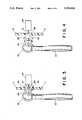
- FIG. 1is a side view of the present invention stun gun showing its wrist strap and low battery indicator light;
- FIG. 2is a side view and partial cut-away of the present invention stun gun, showing its disable switch and key components attached to the wrist strap;
- FIG. 3is an enlarged view of the dashed portion of FIG. 2, wherein the key portion is received into the device housing;
- FIG. 4is an enlarged view of the dashed portion of FIG. 2, wherein the key portion is shown detached from the device housing;
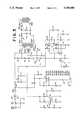
- FIG. 5is a circuit diagram of the improved electronic circuitry of the present invention.
- FIGURESshow the enhanced stun gun of the present invention.
- the present invention stun gunis shown as 10 and is comprised of a housing 11 having a pistol grip 12 and a trigger switch 14.
- the trigger switch 14is located at a position on the housing 11 situated to receive an operator's index finger.
- Extending from the housing 11are a pair of contact probes 16 and test probes 18, the pair of contact probes 16 being used to apply the high voltage generated within the housing 11 to an assailant/victim.
- the housing 11is provided with an aperture 20 through which the low battery indicator LED may be viewed.
- a wrist strap 22At the lower end of housing 11, is a wrist strap 22, through which extends an operator's wrist while gripping the pistol grip 12.
- a ring 23connects the wrist strap 22 with the key 24, the key 24 shown in its engaged/attached position.
- other meansmay be used to attach the key 24 to an operator's person, such as a tether from the ring 23 to an operator's belt loop, shoulder holster, or waist holster.
- FIG. 2a portion of the housing 11 is shown cut-away.
- the key 24is shown received into the housing 11 and in contact with plunger 31 of switch 30.
- the switch 30is fixed mechanically to a circuit board contained within the housing and not shown in detail.
- FIG. 3is an enlarged view of the cut-away portion of FIG. 2 showing the key 24 received into the housing 11.
- key 24is comprised of a pair of barbed, springy legs 26 which, when inserted into the housing 11, serve to "lock" the key 24 therein.
- the key 24is also provided with a centrally located fixed plunger 28 arranged to make contact with and slidably actuate plunger 31 of switch 30.
- the key 24may be made of a relatively durable plastic such that upon insertion into the housing 11, removal may be accomplished only upon application of a predetermined force on ring 23.
- the material and dimensions of ring 24should be selected such that a substantial force should be required to dislodge the key 24 from housing 11.
- FIG. 4wherein the cut-away portion of FIG. 2 is shown in an enlarged view, the key 24 is shown detached from housing 11.
- the spring loaded plunger 31 of switch 30is permitted to slidably extend into its unactuated position in the absence of key 24 and associated centrally located fixed plunger 28.
- the FIGUREshows the pair of barbed, springy legs 26 in their unsprung position and ready for reinsertion into the housing 11 to re-enable the stun gun device upon actuation of plunger 31 into switch 30.
- FIG. 5a circuit diagram of the improved electronic circuitry of the present invention is shown. Power is supplied to the circuit from a battery source BTl.
- the electrical diagrammatic representation of trigger switch 14is shown as switch SWl, wherein closure of the switch SWl connects power source BTI with the inverter transformer TI.
- a classic relaxation oscillatoris formed using a "tickler" winding of inverter transformer T1 shown between the terminals PAD7 and PAD8.
- the primary winding of the inverter transformer T1is shown in the FIGURE having connections at PAD9 and PAD10.
- the primary winding of inverter transformer T1Upon closure of the power switch SW1, the primary winding of inverter transformer T1 is energized as current flows through the winding from PAD9 to PAD10 as the power transistor Q1 conducts.
- the tickler winding of inverter transformer T1is energized upon closure of the power switch SWI through resistor R8 and diode D3.
- the current through the tickler windingalso forms the base current of power transistor Q1, thus causing it to conduct. Since the tickler winding and the primary winding of the inverter transformer T1 oppose one another, the current through power transistor Q1 causes a flux in the inverter transformer T1 to, in effect, backdrive the tickler winding and cut off the power transistor Q1 base current, thus forming the relaxation oscillator.
- the output circuit of the stun gun of the present inventionis shown in FIG. 5 as consisting of the secondary winding of inverter transformer Tl, a pair of diodes D4 and D5, serially connected with a spark gap device GAP and the primary winding of output transformer T2.
- a storage capacitor C10is shown in parallel with bleeder resistor R12 and the primary winding of the output transformer T2.
- the bleeder resistor R12is provided to discharge the storage capacitor at a slow rate to prevent accidental discharge of the device once power has been removed.
- the spark gap device GAPis selected to have particular ionization characteristics tailored to a specific spark gap breakover voltage to "tune" the output circuit.
- the spark gap device GAPis filled with an inert gas such as argon, having a well defined and generally stable permittivity constant to ensure predictability of the spark gap breakover point voltage.
- the output transformer T2is formed having a 26:1080 turns ratio with a primary winding resistance of 0.04 ohms and a secondary resistance of 108 ohms.
- One commercially available output transformer Tlis formed having a trade number 4077375411 ferrite core, having the trademark "FAIR RITE", manufactured by Fair-Rite Products Corp., Wallkill, New York.
- the electrical output waveform of the deviceis a repeating damped sinusoid with a repetition rate of approximately 20 pulses per second.
- the principle frequency component of the sinusoidis approximately 1 MHz.
- the peak voltage present at the electrodes when the output is connected to a resistive load which drops the unloaded voltage to halfis approximately 50,000 volts.
- This measure of source impedanceis about half that of similar stun guns on the market today. The physiological effect of this reduced source impedance is to increase the magnitude of the electrical current impulses or energy delivered to a subject/victim and thereby increase the effectiveness of the stun gun in practical application.
- a 14 stage ripple carry counter U2receives power from power source BTI through diode D6. A charge is stored on capacitor C4 to provide power to the 14 stage ripple carry counter U2 in the event of temporary power interruptions, such as if the device is dropped or the like. In the event that the batteries are removed and power is lost for a prolonged period, the 14 stage ripple carry counter U2 will reset and lose its count as the reset input RST is taken to ground through resistor R5.
- an oscillatorcomprising semiconductor devices Q2 and Q3 is enabled which provides the 14 stage ripple carry counter U2 with a series of pulses through clock input CK.
- the 14 stage ripple carry counter U2continues to increment its count stored therein.
- an output signal Q14goes high, driving a light emitting diode LED thus alerting the operator that the length of time of use of the batteries comprising the power source BTl has exceeded a recommended value, typically 20 minutes.
- the 14 stage ripple carry counter U2Since the above-described low battery indication circuit functions as a counter, and not as an actual evaluation of the batteries comprising the power source BTl, it must be agreed before hand by all using the device that, when replacing batteries, only new batteries will be used because the 14 stage ripple carry counter U2 loses its count upon removal of the batteries from the device. Thus, the 14 stage ripple carry counter U2, unaware of the quality of the replacement batteries, will by virtue of the reset input RST, start to count from a "zero" count anytime the batteries are removed and replaced.
- the build-in shutoff feature of the present inventionis shown in FIG. 5 and comprises a timer integrated circuit chip U1 of the type commonly referred to as "555 timer".
- the integrated circuit chip timer U1is arranged to operate in an a stable condition wherein upon closure of power switch SWI, power is applied to the chip U1 through input pins R and Vd. After a predetermined time period of approximately 15 seconds, the timer integrated circuit chip U1 operates to lower output signal Q to a low logic level, thus causing diode D7 to conduct whereby power transistor Q1 is forced into its nonconducting state. With the power transistor Q1 in its nonconducting state, the oscillator stage will not function and, thus the output circuit is rendered ineffective.
- a continuous closure of power switch SWlwill act to maintain power to the timer integrated circuit chip U1 and after a predetermined time of approximately 5 seconds, the output Q is again returned to its original high logic state wherein diode D7 becomes reverse biased, thus re-enabling power transistor Q1.
- switch SW2Upon insertion of key 24 into housing 11, switch SW2 is opened as shown in the FIGURE. When the key 24 is removed from housing 11, switch SW2 closes thus tying the base of power transistor Q1 to ground. This, in effect, disables the relaxation oscillator and in turn disables the device.
Landscapes
- Engineering & Computer Science (AREA)
- Radar, Positioning & Navigation (AREA)
- Remote Sensing (AREA)
- General Engineering & Computer Science (AREA)
- Life Sciences & Earth Sciences (AREA)
- Insects & Arthropods (AREA)
- Electrotherapy Devices (AREA)
Abstract
Description
Claims (42)
Priority Applications (1)
| Application Number | Priority Date | Filing Date | Title |
|---|---|---|---|
| US07/516,120US5193048A (en) | 1990-04-27 | 1990-04-27 | Stun gun with low battery indicator and shutoff timer |
Applications Claiming Priority (1)
| Application Number | Priority Date | Filing Date | Title |
|---|---|---|---|
| US07/516,120US5193048A (en) | 1990-04-27 | 1990-04-27 | Stun gun with low battery indicator and shutoff timer |
Publications (1)
| Publication Number | Publication Date |
|---|---|
| US5193048Atrue US5193048A (en) | 1993-03-09 |
Family
ID=24054205
Family Applications (1)
| Application Number | Title | Priority Date | Filing Date |
|---|---|---|---|
| US07/516,120Expired - LifetimeUS5193048A (en) | 1990-04-27 | 1990-04-27 | Stun gun with low battery indicator and shutoff timer |
Country Status (1)
| Country | Link |
|---|---|
| US (1) | US5193048A (en) |
Cited By (87)
| Publication number | Priority date | Publication date | Assignee | Title |
|---|---|---|---|---|
| US5404664A (en)* | 1993-12-21 | 1995-04-11 | Brooks; David H. | License plate security frame |
| US5625525A (en)* | 1994-07-11 | 1997-04-29 | Jaycor | Portable electromagnetic stun device and method |
| US5629679A (en)* | 1994-12-15 | 1997-05-13 | Cranford; Richard | Personal security device |
| US5657417A (en)* | 1995-05-02 | 1997-08-12 | Burndy Corporation | Control for battery powered tool |
| US5790023A (en)* | 1994-12-22 | 1998-08-04 | Waters Instruments Inc. | Apparatus and method for control of electric fence |
| US5861127A (en)* | 1997-07-11 | 1999-01-19 | Yeh; Kuo Chung | Portable air purifying apparatus |
| US6536153B2 (en)* | 1998-07-21 | 2003-03-25 | Forrest R. Lindsey | Weapon sling and attachments |
| US20030216792A1 (en)* | 2002-04-08 | 2003-11-20 | Levin Howard R. | Renal nerve stimulation method and apparatus for treatment of patients |
| US20040156162A1 (en)* | 2003-02-11 | 2004-08-12 | Magne Nerheim | Dual operating mode electronic disabling device for generating a time-sequenced, shaped voltage output waveform |
| US20040156163A1 (en)* | 2003-02-11 | 2004-08-12 | Magne Nerheim | Dual operating mode electronic disabling device for generating a time-sequenced, shaped voltage output waveform |
| US20050188827A1 (en)* | 2002-09-09 | 2005-09-01 | Mcnulty James F.Jr. | Electrical discharge weapon for use as a forend grip of rifles |
| US20060025821A1 (en)* | 2002-04-08 | 2006-02-02 | Mark Gelfand | Methods and devices for renal nerve blocking |
| US7042696B2 (en) | 2003-10-07 | 2006-05-09 | Taser International, Inc. | Systems and methods using an electrified projectile |
| US7075770B1 (en) | 1999-09-17 | 2006-07-11 | Taser International, Inc. | Less lethal weapons and methods for halting locomotion |
| US7096792B1 (en)* | 2002-06-25 | 2006-08-29 | Carman Brent G | Sub-lethal, wireless projectile and accessories |
| US20060206150A1 (en)* | 2002-04-08 | 2006-09-14 | Ardian, Inc. | Methods and apparatus for treating acute myocardial infarction |
| US20060235474A1 (en)* | 2002-04-08 | 2006-10-19 | Ardian, Inc. | Methods and apparatus for multi-vessel renal neuromodulation |
| US20060256498A1 (en)* | 2003-10-07 | 2006-11-16 | Taser International, Inc. | Systems and methods for immobilization using charge delivery |
| US20060255775A1 (en)* | 2005-02-22 | 2006-11-16 | Michael Kramer | Electronic disabling device having a non-sinusoidal output waveform |
| US20060279898A1 (en)* | 2003-10-07 | 2006-12-14 | Smith Patrick W | Systems and Methods for Target Impact |
| US20070019358A1 (en)* | 2004-07-13 | 2007-01-25 | Kroll Mark W | Immobilization weapon |
| US20070019357A1 (en)* | 2005-06-22 | 2007-01-25 | Keely William A | High efficiency power supply circuit for an electrical discharge weapon |
| US20070066957A1 (en)* | 2004-11-02 | 2007-03-22 | Ardian, Inc. | Methods and apparatus for inducing controlled renal neuromodulation |
| US20070083239A1 (en)* | 2005-09-23 | 2007-04-12 | Denise Demarais | Methods and apparatus for inducing, monitoring and controlling renal neuromodulation |
| US7221552B1 (en)* | 2006-03-23 | 2007-05-22 | Brown David C | Wearable shield and self-defense device |
| US7237352B2 (en) | 2005-06-22 | 2007-07-03 | Defense Technology Corporation Of America | Projectile for an electrical discharge weapon |
| US20070188972A1 (en)* | 2005-09-13 | 2007-08-16 | Taser International, Inc. | Systems and methods for describing a deployment unit for an electronic |
| US20070203549A1 (en)* | 2005-12-29 | 2007-08-30 | Ardian, Inc. | Methods and apparatus for pulsed electric field neuromodulation via an intra-to-extravascular approach |
| US20070271830A1 (en)* | 2006-05-23 | 2007-11-29 | Holt Jason J | Systems and Methods for Qualified Registration |
| US20080106841A1 (en)* | 2003-05-29 | 2008-05-08 | Nerheim Magne H | Systems And Methods For Immobilization With Variation Of Output Signal Power |
| US20080204965A1 (en)* | 2005-09-13 | 2008-08-28 | Brundula Steven N D | Systems And Methods For Immobilization Using A Compliance Signal Group |
| US20080213331A1 (en)* | 2002-04-08 | 2008-09-04 | Ardian, Inc. | Methods and devices for renal nerve blocking |
| US20090039145A1 (en)* | 2007-08-07 | 2009-02-12 | Per Ib Rosendal Andersen | Stock prodder |
| US20090064557A1 (en)* | 2006-05-23 | 2009-03-12 | Hughes Paul J | Systems And Methods For Conditional Use Of A Product |
| US20090199884A1 (en)* | 2008-02-08 | 2009-08-13 | Reginald David Lessing | Electrical shock defensive walking stick |
| US20090221939A1 (en)* | 2002-04-08 | 2009-09-03 | Ardian, Inc. | Methods and apparatus for thermally-induced renal neuromodulation |
| US20090231776A1 (en)* | 2005-02-22 | 2009-09-17 | Defense Technology Corporation Of America | Electronic disabling device having a non-oscillating output waveform |
| US7631452B1 (en)* | 2005-09-13 | 2009-12-15 | Taser International, Inc. | Systems and methods for electronic weaponry with deployment unit detection |
| US7653438B2 (en) | 2002-04-08 | 2010-01-26 | Ardian, Inc. | Methods and apparatus for renal neuromodulation |
| US20100134090A1 (en)* | 2008-09-23 | 2010-06-03 | Stephen Burns | Stun Device Testing Apparatus and Methods |
| US7736237B2 (en) | 2002-03-01 | 2010-06-15 | Aegis Industries, Inc. | Electromuscular incapacitation device and methods |
| USD618757S1 (en) | 2009-04-30 | 2010-06-29 | Aegis Industries, Inc. | Baton |
| US20100273434A1 (en)* | 2006-09-28 | 2010-10-28 | Nike, Inc. | Sensor device with persistent low power beacon |
| US20100276514A1 (en)* | 2009-04-30 | 2010-11-04 | Stethem Kenneth J | Multi-Stimulus Personal Defense Device |
| US20110013337A1 (en)* | 2008-05-08 | 2011-01-20 | Armstar, Inc. | Wearable shield and self-defense device including multiple integrated components |
| US20110143648A1 (en)* | 2005-01-06 | 2011-06-16 | Oy Halton Group Ltd. | Automatic displacement ventilation system with heating mode |
| US7986506B2 (en) | 2006-05-03 | 2011-07-26 | Taser International, Inc. | Systems and methods for arc energy regulation and pulse delivery |
| US20110208096A1 (en)* | 2002-04-08 | 2011-08-25 | Ardian, Inc. | Methods and apparatus for thermally-induced renal neuromodulation |
| US20110207758A1 (en)* | 2003-04-08 | 2011-08-25 | Medtronic Vascular, Inc. | Methods for Therapeutic Renal Denervation |
| US8031078B1 (en)* | 2008-09-03 | 2011-10-04 | Liestman Richard E | Key chain holder with clock and alarm |
| US8131371B2 (en) | 2002-04-08 | 2012-03-06 | Ardian, Inc. | Methods and apparatus for monopolar renal neuromodulation |
| US8145316B2 (en) | 2002-04-08 | 2012-03-27 | Ardian, Inc. | Methods and apparatus for renal neuromodulation |
| US8145317B2 (en) | 2002-04-08 | 2012-03-27 | Ardian, Inc. | Methods for renal neuromodulation |
| US8150519B2 (en) | 2002-04-08 | 2012-04-03 | Ardian, Inc. | Methods and apparatus for bilateral renal neuromodulation |
| US8347891B2 (en) | 2002-04-08 | 2013-01-08 | Medtronic Ardian Luxembourg S.A.R.L. | Methods and apparatus for performing a non-continuous circumferential treatment of a body lumen |
| US8620423B2 (en) | 2002-04-08 | 2013-12-31 | Medtronic Ardian Luxembourg S.A.R.L. | Methods for thermal modulation of nerves contributing to renal function |
| US8774922B2 (en) | 2002-04-08 | 2014-07-08 | Medtronic Ardian Luxembourg S.A.R.L. | Catheter apparatuses having expandable balloons for renal neuromodulation and associated systems and methods |
| US8771085B1 (en) | 2010-08-06 | 2014-07-08 | Arthur C. Clyde | Modular law enforcement baton |
| US8774913B2 (en) | 2002-04-08 | 2014-07-08 | Medtronic Ardian Luxembourg S.A.R.L. | Methods and apparatus for intravasculary-induced neuromodulation |
| US8818514B2 (en) | 2002-04-08 | 2014-08-26 | Medtronic Ardian Luxembourg S.A.R.L. | Methods for intravascularly-induced neuromodulation |
| US8861169B2 (en) | 2013-02-25 | 2014-10-14 | Bradshaw Defense, Llc | Animal defense system and method of use |
| US8976024B2 (en) | 2011-04-15 | 2015-03-10 | Taser International, Inc. | Systems and methods for electronic control device with deactivation alert |
| US9308044B2 (en) | 2002-04-08 | 2016-04-12 | Medtronic Ardian Luxembourg S.A.R.L. | Methods for therapeutic renal neuromodulation |
| US9308043B2 (en) | 2002-04-08 | 2016-04-12 | Medtronic Ardian Luxembourg S.A.R.L. | Methods for monopolar renal neuromodulation |
| US9327122B2 (en) | 2002-04-08 | 2016-05-03 | Medtronic Ardian Luxembourg S.A.R.L. | Methods for catheter-based renal neuromodulation |
| US9439726B2 (en) | 2002-04-08 | 2016-09-13 | Medtronic Ardian Luxembourg S.A.R.L. | Methods for therapeutic renal neuromodulation |
| US20160327375A1 (en)* | 2015-05-07 | 2016-11-10 | Naim Alherimi | Hand-held personal-protection shock device |
| USD778396S1 (en) | 2015-09-01 | 2017-02-07 | Aegis Industries, Inc. | Baton |
| USD802078S1 (en) | 2016-05-06 | 2017-11-07 | Aegis Industries, Inc. | Baton |
| USD802706S1 (en) | 2016-05-06 | 2017-11-14 | Aegis Industries, Inc. | Baton |
| USD815242S1 (en) | 2015-12-10 | 2018-04-10 | Aegis Industries, Inc. | Baton |
| US9980766B1 (en) | 2014-03-28 | 2018-05-29 | Medtronic Ardian Luxembourg S.A.R.L. | Methods and systems for renal neuromodulation |
| USD822377S1 (en)* | 2017-01-19 | 2018-07-10 | Yasar Sheikh | Keychain stun gun |
| US10080864B2 (en) | 2012-10-19 | 2018-09-25 | Medtronic Ardian Luxembourg S.A.R.L. | Packaging for catheter treatment devices and associated devices, systems, and methods |
| WO2018189594A2 (en) | 2017-01-14 | 2018-10-18 | Leonidas Ip, Llc | Cew weapon system and related methods |
| US10179020B2 (en) | 2010-10-25 | 2019-01-15 | Medtronic Ardian Luxembourg S.A.R.L. | Devices, systems and methods for evaluation and feedback of neuromodulation treatment |
| US10194980B1 (en) | 2014-03-28 | 2019-02-05 | Medtronic Ardian Luxembourg S.A.R.L. | Methods for catheter-based renal neuromodulation |
| US10194979B1 (en) | 2014-03-28 | 2019-02-05 | Medtronic Ardian Luxembourg S.A.R.L. | Methods for catheter-based renal neuromodulation |
| US10473438B2 (en)* | 2016-02-23 | 2019-11-12 | Axon Enterprise, Inc. | Methods and apparatus for a conducted electrical weapon |
| US10537385B2 (en) | 2008-12-31 | 2020-01-21 | Medtronic Ardian Luxembourg S.A.R.L. | Intravascular, thermally-induced renal neuromodulation for treatment of polycystic ovary syndrome or infertility |
| US10874455B2 (en) | 2012-03-08 | 2020-12-29 | Medtronic Ardian Luxembourg S.A.R.L. | Ovarian neuromodulation and associated systems and methods |
| US10989502B2 (en) | 2016-02-23 | 2021-04-27 | Axon Enterprise, Inc. | Methods and apparatus for a conducted electrical weapon |
| US11338140B2 (en) | 2012-03-08 | 2022-05-24 | Medtronic Ardian Luxembourg S.A.R.L. | Monitoring of neuromodulation using biomarkers |
| US20230092622A1 (en)* | 2021-09-22 | 2023-03-23 | Axon Enterprise, Inc. | Generating alerts based on connection status by conducted electrical weapons |
| US12326321B2 (en) | 2017-07-31 | 2025-06-10 | Far East-West Trading Company, Llc | Glove adapted to dispense pulsed electric current to a human's skin |
| US12332026B2 (en) | 2017-07-31 | 2025-06-17 | Compliant Technologies Llc | Device deterring movement of a detainee |
| USD1095737S1 (en)* | 2021-09-30 | 2025-09-30 | Axon Enterprise, Inc. | Electrical weapon |
Citations (15)
| Publication number | Priority date | Publication date | Assignee | Title |
|---|---|---|---|---|
| US3724744A (en)* | 1971-11-26 | 1973-04-03 | W Carnahan | Card holder for meter readers |
| US3803463A (en)* | 1972-07-10 | 1974-04-09 | J Cover | Weapon for immobilization and capture |
| US3819108A (en)* | 1972-08-28 | 1974-06-25 | Gen Marine | Crowd control stick |
| US3885733A (en)* | 1973-03-27 | 1975-05-27 | Franklin R Klebold | New electric prod |
| US3917268A (en)* | 1974-06-10 | 1975-11-04 | H & T Ind | Spark gap type electric shock-producing prod |
| US3998459A (en)* | 1975-02-10 | 1976-12-21 | American Home Products Corporation | Electrical shocking device |
| US4037683A (en)* | 1975-10-20 | 1977-07-26 | Lebell Gene | Motorvehicle safety cut-out switch |
| US4092695A (en)* | 1976-12-20 | 1978-05-30 | American Home Products Corporation | Electrical shocking device |
| US4162515A (en)* | 1976-12-20 | 1979-07-24 | American Home Products Corp. | Electrical shocking device with audible and visible spark display |
| US4253132A (en)* | 1977-12-29 | 1981-02-24 | Cover John H | Power supply for weapon for immobilization and capture |
| US4424932A (en)* | 1982-03-19 | 1984-01-10 | Allen Gerald F | Electric shock prod |
| US4486807A (en)* | 1982-02-16 | 1984-12-04 | Yanez Serge J | Non-lethal self defense device |
| US4502030A (en)* | 1983-08-26 | 1985-02-26 | Allied Corporation | High reliability solenoid switch |
| US4688140A (en)* | 1985-10-28 | 1987-08-18 | John Hammes | Electronic defensive weapon |
| US4872084A (en)* | 1988-09-06 | 1989-10-03 | U.S. Protectors, Inc. | Enhanced electrical shocking device with improved long life and increased power circuitry |
- 1990
- 1990-04-27USUS07/516,120patent/US5193048A/ennot_activeExpired - Lifetime
Patent Citations (15)
| Publication number | Priority date | Publication date | Assignee | Title |
|---|---|---|---|---|
| US3724744A (en)* | 1971-11-26 | 1973-04-03 | W Carnahan | Card holder for meter readers |
| US3803463A (en)* | 1972-07-10 | 1974-04-09 | J Cover | Weapon for immobilization and capture |
| US3819108A (en)* | 1972-08-28 | 1974-06-25 | Gen Marine | Crowd control stick |
| US3885733A (en)* | 1973-03-27 | 1975-05-27 | Franklin R Klebold | New electric prod |
| US3917268A (en)* | 1974-06-10 | 1975-11-04 | H & T Ind | Spark gap type electric shock-producing prod |
| US3998459A (en)* | 1975-02-10 | 1976-12-21 | American Home Products Corporation | Electrical shocking device |
| US4037683A (en)* | 1975-10-20 | 1977-07-26 | Lebell Gene | Motorvehicle safety cut-out switch |
| US4092695A (en)* | 1976-12-20 | 1978-05-30 | American Home Products Corporation | Electrical shocking device |
| US4162515A (en)* | 1976-12-20 | 1979-07-24 | American Home Products Corp. | Electrical shocking device with audible and visible spark display |
| US4253132A (en)* | 1977-12-29 | 1981-02-24 | Cover John H | Power supply for weapon for immobilization and capture |
| US4486807A (en)* | 1982-02-16 | 1984-12-04 | Yanez Serge J | Non-lethal self defense device |
| US4424932A (en)* | 1982-03-19 | 1984-01-10 | Allen Gerald F | Electric shock prod |
| US4502030A (en)* | 1983-08-26 | 1985-02-26 | Allied Corporation | High reliability solenoid switch |
| US4688140A (en)* | 1985-10-28 | 1987-08-18 | John Hammes | Electronic defensive weapon |
| US4872084A (en)* | 1988-09-06 | 1989-10-03 | U.S. Protectors, Inc. | Enhanced electrical shocking device with improved long life and increased power circuitry |
Cited By (245)
| Publication number | Priority date | Publication date | Assignee | Title |
|---|---|---|---|---|
| US5404664A (en)* | 1993-12-21 | 1995-04-11 | Brooks; David H. | License plate security frame |
| US5625525A (en)* | 1994-07-11 | 1997-04-29 | Jaycor | Portable electromagnetic stun device and method |
| US5629679A (en)* | 1994-12-15 | 1997-05-13 | Cranford; Richard | Personal security device |
| US5790023A (en)* | 1994-12-22 | 1998-08-04 | Waters Instruments Inc. | Apparatus and method for control of electric fence |
| US5657417A (en)* | 1995-05-02 | 1997-08-12 | Burndy Corporation | Control for battery powered tool |
| US5861127A (en)* | 1997-07-11 | 1999-01-19 | Yeh; Kuo Chung | Portable air purifying apparatus |
| US6536153B2 (en)* | 1998-07-21 | 2003-03-25 | Forrest R. Lindsey | Weapon sling and attachments |
| US7082709B2 (en)* | 1998-07-21 | 2006-08-01 | Lindsey Forrest R | Weapon sling and attachments |
| US7075770B1 (en) | 1999-09-17 | 2006-07-11 | Taser International, Inc. | Less lethal weapons and methods for halting locomotion |
| US7234262B2 (en)* | 1999-09-17 | 2007-06-26 | Taser International, Inc. | Electrical weapon having controller for timed current through target and date/time recording |
| US20070097592A1 (en)* | 1999-09-17 | 2007-05-03 | Taser International, Inc. | Electrical weapon having controller for timed current through target and date/time recording |
| US8277328B2 (en) | 2002-03-01 | 2012-10-02 | Aegis Industries, Inc. | Electromuscular incapacitation device and methods |
| US7736237B2 (en) | 2002-03-01 | 2010-06-15 | Aegis Industries, Inc. | Electromuscular incapacitation device and methods |
| US9731132B2 (en) | 2002-04-08 | 2017-08-15 | Medtronic Ardian Luxembourg S.A.R.L. | Methods for renal neuromodulation |
| US9757192B2 (en) | 2002-04-08 | 2017-09-12 | Medtronic Ardian Luxembourg S.A.R.L. | Renal neuromodulation for treatment of patients |
| US20060025821A1 (en)* | 2002-04-08 | 2006-02-02 | Mark Gelfand | Methods and devices for renal nerve blocking |
| US11033328B2 (en) | 2002-04-08 | 2021-06-15 | Medtronic Ardian Luxembourg S.A.R.L. | Methods and apparatus for renal neuromodulation |
| US10850091B2 (en) | 2002-04-08 | 2020-12-01 | Medtronic Ardian Luxembourg S.A.R.L. | Methods and apparatus for bilateral renal neuromodulation |
| US20050228460A1 (en)* | 2002-04-08 | 2005-10-13 | Levin Howard R | Renal nerve stimulation method and apparatus for treatment of patients |
| US20050228459A1 (en)* | 2002-04-08 | 2005-10-13 | Levin Howard R | Renal nerve stimulation method and apparatus for treatment of patients |
| US10441356B2 (en) | 2002-04-08 | 2019-10-15 | Medtronic Ardian Luxembourg S.A.R.L. | Methods for renal neuromodulation via neuromodulatory agents |
| US10420606B2 (en) | 2002-04-08 | 2019-09-24 | Medtronic Ardian Luxembourg S.A.R.L. | Methods and apparatus for performing a non-continuous circumferential treatment of a body lumen |
| US20060206150A1 (en)* | 2002-04-08 | 2006-09-14 | Ardian, Inc. | Methods and apparatus for treating acute myocardial infarction |
| US20060212076A1 (en)* | 2002-04-08 | 2006-09-21 | Ardian, Inc. | Methods and apparatus for treating end-stage renal disease |
| US20060235474A1 (en)* | 2002-04-08 | 2006-10-19 | Ardian, Inc. | Methods and apparatus for multi-vessel renal neuromodulation |
| US10376312B2 (en) | 2002-04-08 | 2019-08-13 | Medtronic Ardian Luxembourg S.A.R.L. | Methods and apparatus for monopolar renal neuromodulation |
| US10376311B2 (en) | 2002-04-08 | 2019-08-13 | Medtronic Ardian Luxembourg S.A.R.L. | Methods and apparatus for intravascularly-induced neuromodulation |
| US20060271111A1 (en)* | 2002-04-08 | 2006-11-30 | Ardian, Inc. | Methods and apparatus for treating contrast nephropathy |
| US10376516B2 (en) | 2002-04-08 | 2019-08-13 | Medtronic Ardian Luxembourg S.A.R.L. | Methods and devices for renal nerve blocking |
| US8728137B2 (en) | 2002-04-08 | 2014-05-20 | Medtronic Ardian Luxembourg S.A.R.L. | Methods for thermally-induced renal neuromodulation |
| US7162303B2 (en) | 2002-04-08 | 2007-01-09 | Ardian, Inc. | Renal nerve stimulation method and apparatus for treatment of patients |
| US10293190B2 (en) | 2002-04-08 | 2019-05-21 | Medtronic Ardian Luxembourg S.A.R.L. | Thermally-induced renal neuromodulation and associated systems and methods |
| US10272246B2 (en) | 2002-04-08 | 2019-04-30 | Medtronic Adrian Luxembourg S.a.r.l | Methods for extravascular renal neuromodulation |
| US10245429B2 (en) | 2002-04-08 | 2019-04-02 | Medtronic Ardian Luxembourg S.A.R.L. | Methods and apparatus for renal neuromodulation |
| US8728138B2 (en) | 2002-04-08 | 2014-05-20 | Medtronic Ardian Luxembourg S.A.R.L. | Methods for thermally-induced renal neuromodulation |
| US10179028B2 (en) | 2002-04-08 | 2019-01-15 | Medtronic Ardian Luxembourg S.A.R.L. | Methods for treating patients via renal neuromodulation |
| US10179027B2 (en) | 2002-04-08 | 2019-01-15 | Medtronic Ardian Luxembourg S.A.R.L. | Catheter apparatuses having expandable baskets for renal neuromodulation and associated systems and methods |
| US10179235B2 (en) | 2002-04-08 | 2019-01-15 | Medtronic Ardian Luxembourg S.A.R.L. | Methods and apparatus for bilateral renal neuromodulation |
| US10130792B2 (en) | 2002-04-08 | 2018-11-20 | Medtronic Ardian Luxembourg S.A.R.L. | Methods for therapeutic renal neuromodulation using neuromodulatory agents or drugs |
| US10124195B2 (en) | 2002-04-08 | 2018-11-13 | Medtronic Ardian Luxembourg S.A.R.L. | Methods for thermally-induced renal neuromodulation |
| US10111707B2 (en) | 2002-04-08 | 2018-10-30 | Medtronic Ardian Luxembourg S.A.R.L. | Renal neuromodulation for treatment of human patients |
| US10105180B2 (en) | 2002-04-08 | 2018-10-23 | Medtronic Ardian Luxembourg S.A.R.L. | Methods and apparatus for intravascularly-induced neuromodulation |
| US10039596B2 (en) | 2002-04-08 | 2018-08-07 | Medtronic Ardian Luxembourg S.A.R.L. | Apparatus for renal neuromodulation via an intra-to-extravascular approach |
| US20070173899A1 (en)* | 2002-04-08 | 2007-07-26 | Ardian, Inc. | Renal nerve stimulation method for treatment of patients |
| US10034708B2 (en) | 2002-04-08 | 2018-07-31 | Medtronic Ardian Luxembourg S.A.R.L. | Methods and apparatus for thermally-induced renal neuromodulation |
| US9968611B2 (en) | 2002-04-08 | 2018-05-15 | Medtronic Ardian Luxembourg S.A.R.L. | Methods and devices for renal nerve blocking |
| US9956410B2 (en) | 2002-04-08 | 2018-05-01 | Medtronic Ardian Luxembourg S.A.R.L. | Methods and apparatus for renal neuromodulation |
| US9907611B2 (en) | 2002-04-08 | 2018-03-06 | Medtronic Ardian Luxembourg S.A.R.L. | Renal neuromodulation for treatment of patients |
| US9895195B2 (en) | 2002-04-08 | 2018-02-20 | Medtronic Ardian Luxembourg S.A.R.L. | Methods for therapeutic renal neuromodulation |
| US9827041B2 (en) | 2002-04-08 | 2017-11-28 | Medtronic Ardian Luxembourg S.A.R.L. | Balloon catheter apparatuses for renal denervation |
| US9827040B2 (en) | 2002-04-08 | 2017-11-28 | Medtronic Adrian Luxembourg S.a.r.l. | Methods and apparatus for intravascularly-induced neuromodulation |
| US9814873B2 (en) | 2002-04-08 | 2017-11-14 | Medtronic Ardian Luxembourg S.A.R.L. | Methods and apparatus for bilateral renal neuromodulation |
| US8721637B2 (en) | 2002-04-08 | 2014-05-13 | Medtronic Ardian Luxembourg S.A.R.L. | Methods and apparatus for performing renal neuromodulation via catheter apparatuses having inflatable balloons |
| US9757193B2 (en) | 2002-04-08 | 2017-09-12 | Medtronic Ardian Luxembourg S.A.R.L. | Balloon catheter apparatus for renal neuromodulation |
| US20080213331A1 (en)* | 2002-04-08 | 2008-09-04 | Ardian, Inc. | Methods and devices for renal nerve blocking |
| US20050234523A1 (en)* | 2002-04-08 | 2005-10-20 | Levin Howard R | Renal nerve stimulation method and apparatus for treatment of patients |
| US9743983B2 (en) | 2002-04-08 | 2017-08-29 | Medtronic Ardian Luxembourg S.A.R.L. | Renal neuromodulation for treatment of patients |
| US20030216792A1 (en)* | 2002-04-08 | 2003-11-20 | Levin Howard R. | Renal nerve stimulation method and apparatus for treatment of patients |
| US9707035B2 (en) | 2002-04-08 | 2017-07-18 | Medtronic Ardian Luxembourg S.A.R.L. | Methods for catheter-based renal neuromodulation |
| US9675413B2 (en) | 2002-04-08 | 2017-06-13 | Medtronic Ardian Luxembourg S.A.R.L. | Methods and apparatus for renal neuromodulation |
| US9636174B2 (en) | 2002-04-08 | 2017-05-02 | Medtronic Ardian Luxembourg S.A.R.L. | Methods for therapeutic renal neuromodulation |
| US9486270B2 (en) | 2002-04-08 | 2016-11-08 | Medtronic Ardian Luxembourg S.A.R.L. | Methods and apparatus for bilateral renal neuromodulation |
| US20090221939A1 (en)* | 2002-04-08 | 2009-09-03 | Ardian, Inc. | Methods and apparatus for thermally-induced renal neuromodulation |
| US9474563B2 (en) | 2002-04-08 | 2016-10-25 | Medtronic Ardian Luxembourg S.A.R.L. | Methods for renal neuromodulation |
| US9468497B2 (en) | 2002-04-08 | 2016-10-18 | Medtronic Ardian Luxembourg S.A.R.L. | Methods for monopolar renal neuromodulation |
| US9463066B2 (en) | 2002-04-08 | 2016-10-11 | Medtronic Ardian Luxembourg S.A.R.L. | Methods for renal neuromodulation |
| US9456869B2 (en) | 2002-04-08 | 2016-10-04 | Medtronic Ardian Luxembourg S.A.R.L. | Methods for bilateral renal neuromodulation |
| US9445867B1 (en) | 2002-04-08 | 2016-09-20 | Medtronic Ardian Luxembourg S.A.R.L. | Methods for renal neuromodulation via catheters having expandable treatment members |
| US7617005B2 (en) | 2002-04-08 | 2009-11-10 | Ardian, Inc. | Methods and apparatus for thermally-induced renal neuromodulation |
| US9439726B2 (en) | 2002-04-08 | 2016-09-13 | Medtronic Ardian Luxembourg S.A.R.L. | Methods for therapeutic renal neuromodulation |
| US9364280B2 (en) | 2002-04-08 | 2016-06-14 | Medtronic Ardian Luxembourg S.A.R.L. | Methods and apparatus for pulsed electric field neuromodulation via an intra-to-extravascular approach |
| US7647115B2 (en) | 2002-04-08 | 2010-01-12 | Ardian, Inc. | Renal nerve stimulation method and apparatus for treatment of patients |
| US7653438B2 (en) | 2002-04-08 | 2010-01-26 | Ardian, Inc. | Methods and apparatus for renal neuromodulation |
| US7717948B2 (en) | 2002-04-08 | 2010-05-18 | Ardian, Inc. | Methods and apparatus for thermally-induced renal neuromodulation |
| US9326817B2 (en) | 2002-04-08 | 2016-05-03 | Medtronic Ardian Luxembourg S.A.R.L. | Methods for treating heart arrhythmia |
| US9327122B2 (en) | 2002-04-08 | 2016-05-03 | Medtronic Ardian Luxembourg S.A.R.L. | Methods for catheter-based renal neuromodulation |
| US9320561B2 (en) | 2002-04-08 | 2016-04-26 | Medtronic Ardian Luxembourg S.A.R.L. | Methods for bilateral renal neuromodulation |
| US9314630B2 (en) | 2002-04-08 | 2016-04-19 | Medtronic Ardian Luxembourg S.A.R.L. | Renal neuromodulation for treatment of patients |
| US9308043B2 (en) | 2002-04-08 | 2016-04-12 | Medtronic Ardian Luxembourg S.A.R.L. | Methods for monopolar renal neuromodulation |
| US9308044B2 (en) | 2002-04-08 | 2016-04-12 | Medtronic Ardian Luxembourg S.A.R.L. | Methods for therapeutic renal neuromodulation |
| US9289255B2 (en) | 2002-04-08 | 2016-03-22 | Medtronic Ardian Luxembourg S.A.R.L. | Methods and apparatus for renal neuromodulation |
| US7853333B2 (en) | 2002-04-08 | 2010-12-14 | Ardian, Inc. | Methods and apparatus for multi-vessel renal neuromodulation |
| US9265558B2 (en) | 2002-04-08 | 2016-02-23 | Medtronic Ardian Luxembourg S.A.R.L. | Methods for bilateral renal neuromodulation |
| US9192715B2 (en) | 2002-04-08 | 2015-11-24 | Medtronic Ardian Luxembourg S.A.R.L. | Methods for renal nerve blocking |
| US9186213B2 (en) | 2002-04-08 | 2015-11-17 | Medtronic Ardian Luxembourg S.A.R.L. | Methods for renal neuromodulation |
| US9186198B2 (en) | 2002-04-08 | 2015-11-17 | Medtronic Ardian Luxembourg S.A.R.L. | Ultrasound apparatuses for thermally-induced renal neuromodulation and associated systems and methods |
| US9138281B2 (en) | 2002-04-08 | 2015-09-22 | Medtronic Ardian Luxembourg S.A.R.L. | Methods for bilateral renal neuromodulation via catheter apparatuses having expandable baskets |
| US9131978B2 (en) | 2002-04-08 | 2015-09-15 | Medtronic Ardian Luxembourg S.A.R.L. | Methods for bilateral renal neuromodulation |
| US9125661B2 (en) | 2002-04-08 | 2015-09-08 | Medtronic Ardian Luxembourg S.A.R.L. | Methods and apparatus for renal neuromodulation |
| US9072527B2 (en) | 2002-04-08 | 2015-07-07 | Medtronic Ardian Luxembourg S.A.R.L. | Apparatuses and methods for renal neuromodulation |
| US9023037B2 (en) | 2002-04-08 | 2015-05-05 | Medtronic Ardian Luxembourg S.A.R.L. | Balloon catheter apparatus for renal neuromodulation |
| US8986294B2 (en) | 2002-04-08 | 2015-03-24 | Medtronic Ardian Luxembourg S.a.rl. | Apparatuses for thermally-induced renal neuromodulation |
| US8983595B2 (en) | 2002-04-08 | 2015-03-17 | Medtronic Ardian Luxembourg S.A.R.L. | Renal neuromodulation for treatment of patients with chronic heart failure |
| US8958871B2 (en) | 2002-04-08 | 2015-02-17 | Medtronic Ardian Luxembourg S.A.R.L. | Methods and apparatus for pulsed electric field neuromodulation via an intra-to-extravascular approach |
| US20110208096A1 (en)* | 2002-04-08 | 2011-08-25 | Ardian, Inc. | Methods and apparatus for thermally-induced renal neuromodulation |
| US8948865B2 (en) | 2002-04-08 | 2015-02-03 | Medtronic Ardian Luxembourg S.A.R.L. | Methods for treating heart arrhythmia |
| US8934978B2 (en) | 2002-04-08 | 2015-01-13 | Medtronic Ardian Luxembourg S.A.R.L. | Methods and apparatus for renal neuromodulation |
| US8880186B2 (en) | 2002-04-08 | 2014-11-04 | Medtronic Ardian Luxembourg S.A.R.L. | Renal neuromodulation for treatment of patients with chronic heart failure |
| US8852163B2 (en) | 2002-04-08 | 2014-10-07 | Medtronic Ardian Luxembourg S.A.R.L. | Renal neuromodulation via drugs and neuromodulatory agents and associated systems and methods |
| US8845629B2 (en) | 2002-04-08 | 2014-09-30 | Medtronic Ardian Luxembourg S.A.R.L. | Ultrasound apparatuses for thermally-induced renal neuromodulation |
| US8818514B2 (en) | 2002-04-08 | 2014-08-26 | Medtronic Ardian Luxembourg S.A.R.L. | Methods for intravascularly-induced neuromodulation |
| US8784463B2 (en) | 2002-04-08 | 2014-07-22 | Medtronic Ardian Luxembourg S.A.R.L. | Methods for thermally-induced renal neuromodulation |
| US8771252B2 (en) | 2002-04-08 | 2014-07-08 | Medtronic Ardian Luxembourg S.A.R.L. | Methods and devices for renal nerve blocking |
| US8131372B2 (en) | 2002-04-08 | 2012-03-06 | Ardian, Inc. | Renal nerve stimulation method for treatment of patients |
| US8131371B2 (en) | 2002-04-08 | 2012-03-06 | Ardian, Inc. | Methods and apparatus for monopolar renal neuromodulation |
| US8145316B2 (en) | 2002-04-08 | 2012-03-27 | Ardian, Inc. | Methods and apparatus for renal neuromodulation |
| US8145317B2 (en) | 2002-04-08 | 2012-03-27 | Ardian, Inc. | Methods for renal neuromodulation |
| US8150519B2 (en) | 2002-04-08 | 2012-04-03 | Ardian, Inc. | Methods and apparatus for bilateral renal neuromodulation |
| US8150518B2 (en) | 2002-04-08 | 2012-04-03 | Ardian, Inc. | Renal nerve stimulation method and apparatus for treatment of patients |
| US8150520B2 (en) | 2002-04-08 | 2012-04-03 | Ardian, Inc. | Methods for catheter-based renal denervation |
| US8774913B2 (en) | 2002-04-08 | 2014-07-08 | Medtronic Ardian Luxembourg S.A.R.L. | Methods and apparatus for intravasculary-induced neuromodulation |
| US8774922B2 (en) | 2002-04-08 | 2014-07-08 | Medtronic Ardian Luxembourg S.A.R.L. | Catheter apparatuses having expandable balloons for renal neuromodulation and associated systems and methods |
| US8175711B2 (en) | 2002-04-08 | 2012-05-08 | Ardian, Inc. | Methods for treating a condition or disease associated with cardio-renal function |
| US8768470B2 (en) | 2002-04-08 | 2014-07-01 | Medtronic Ardian Luxembourg S.A.R.L. | Methods for monitoring renal neuromodulation |
| US8740896B2 (en) | 2002-04-08 | 2014-06-03 | Medtronic Ardian Luxembourg S.A.R.L. | Methods and apparatus for performing renal neuromodulation via catheter apparatuses having inflatable balloons |
| US8684998B2 (en) | 2002-04-08 | 2014-04-01 | Medtronic Ardian Luxembourg S.A.R.L. | Methods for inhibiting renal nerve activity |
| US8626300B2 (en) | 2002-04-08 | 2014-01-07 | Medtronic Ardian Luxembourg S.A.R.L. | Methods and apparatus for thermally-induced renal neuromodulation |
| US8347891B2 (en) | 2002-04-08 | 2013-01-08 | Medtronic Ardian Luxembourg S.A.R.L. | Methods and apparatus for performing a non-continuous circumferential treatment of a body lumen |
| US8620423B2 (en) | 2002-04-08 | 2013-12-31 | Medtronic Ardian Luxembourg S.A.R.L. | Methods for thermal modulation of nerves contributing to renal function |
| US8444640B2 (en) | 2002-04-08 | 2013-05-21 | Medtronic Ardian Luxembourg S.A.R.L. | Methods and apparatus for performing a non-continuous circumferential treatment of a body lumen |
| US8454594B2 (en) | 2002-04-08 | 2013-06-04 | Medtronic Ardian Luxembourg S.A.R.L. | Apparatus for performing a non-continuous circumferential treatment of a body lumen |
| US8548600B2 (en) | 2002-04-08 | 2013-10-01 | Medtronic Ardian Luxembourg S.A.R.L. | Apparatuses for renal neuromodulation and associated systems and methods |
| US8551069B2 (en) | 2002-04-08 | 2013-10-08 | Medtronic Adrian Luxembourg S.a.r.l. | Methods and apparatus for treating contrast nephropathy |
| US7096792B1 (en)* | 2002-06-25 | 2006-08-29 | Carman Brent G | Sub-lethal, wireless projectile and accessories |
| US20050188827A1 (en)* | 2002-09-09 | 2005-09-01 | Mcnulty James F.Jr. | Electrical discharge weapon for use as a forend grip of rifles |
| AU2011201757B2 (en)* | 2003-02-11 | 2011-11-03 | Taser International, Inc. | Electronic Disabling Device |
| AU2010201941B2 (en)* | 2003-02-11 | 2011-01-20 | Taser International, Inc. | Electronic Disabling Device |
| US20110050177A1 (en)* | 2003-02-11 | 2011-03-03 | Taser International, Inc. | Systems and methods for predicting remaining battery capacity |
| US20070133146A1 (en)* | 2003-02-11 | 2007-06-14 | Nerheim Magne H | Dual Operating Mode Electronic Disabling Device |
| AU2011201759B2 (en)* | 2003-02-11 | 2011-11-03 | Taser International, Inc. | Electronic Disabling Device |
| US6999295B2 (en) | 2003-02-11 | 2006-02-14 | Watkins Iii Thomas G | Dual operating mode electronic disabling device for generating a time-sequenced, shaped voltage output waveform |
| US7936552B2 (en) | 2003-02-11 | 2011-05-03 | Taser International, Inc. | Systems and methods for immobilizing with change of impedance |
| US7145762B2 (en) | 2003-02-11 | 2006-12-05 | Taser International, Inc. | Systems and methods for immobilizing using plural energy stores |
| US7782592B2 (en) | 2003-02-11 | 2010-08-24 | Taser International, Inc. | Dual operating mode electronic disabling device |
| US20050188888A1 (en)* | 2003-02-11 | 2005-09-01 | Watkins Thomas G.Iii | Dual operating mode electronic disabling device for generating a time-sequenced, shaped voltage output waveform |
| US20110043961A1 (en)* | 2003-02-11 | 2011-02-24 | Nerheim Magne H | Systems and methods for immobilizing with change of impedance |
| US20040156163A1 (en)* | 2003-02-11 | 2004-08-12 | Magne Nerheim | Dual operating mode electronic disabling device for generating a time-sequenced, shaped voltage output waveform |
| US20040156162A1 (en)* | 2003-02-11 | 2004-08-12 | Magne Nerheim | Dual operating mode electronic disabling device for generating a time-sequenced, shaped voltage output waveform |
| US20070109712A1 (en)* | 2003-02-11 | 2007-05-17 | Nerheim Magne H | Systems and Methods for Immobilizing Using Waveform Shaping |
| US7602598B2 (en) | 2003-02-11 | 2009-10-13 | Taser International, Inc. | Systems and methods for immobilizing using waveform shaping |
| AU2011201760B2 (en)* | 2003-02-11 | 2011-11-03 | Taser International, Inc. | Electronic Disabling Device |
| AU2011201756B2 (en)* | 2003-02-11 | 2011-11-03 | Taser International, Inc. | Electronic Disabling Device |
| US7102870B2 (en) | 2003-02-11 | 2006-09-05 | Taser International, Inc. | Systems and methods for managing battery power in an electronic disabling device |
| US8045316B2 (en) | 2003-02-11 | 2011-10-25 | Taser International, Inc. | Systems and methods for predicting remaining battery capacity |
| US20110207758A1 (en)* | 2003-04-08 | 2011-08-25 | Medtronic Vascular, Inc. | Methods for Therapeutic Renal Denervation |
| US20080106841A1 (en)* | 2003-05-29 | 2008-05-08 | Nerheim Magne H | Systems And Methods For Immobilization With Variation Of Output Signal Power |
| US20080123240A1 (en)* | 2003-05-29 | 2008-05-29 | Nerheim Magne H | Systems and Methods For Immobilization With Repetition Rate Control |
| US7586733B2 (en)* | 2003-05-29 | 2009-09-08 | Taser International, Inc. | Systems and methods for immobilization with time monitoring |
| US20080130193A1 (en)* | 2003-05-29 | 2008-06-05 | Nerheim Magne H | Systems And Methods For An Electronic Control Device With Date And Time Recording |
| US7916446B2 (en) | 2003-05-29 | 2011-03-29 | Taser International, Inc. | Systems and methods for immobilization with variation of output signal power |
| US7580237B2 (en) | 2003-05-29 | 2009-08-25 | Taser International, Inc. | Systems and methods for immobilization with repetition rate control |
| US7570476B2 (en) | 2003-05-29 | 2009-08-04 | Taser International, Inc. | Systems and methods for an electronic control device with date and time recording |
| US20080130192A1 (en)* | 2003-05-29 | 2008-06-05 | Nerheim Magne H | Systems And Methods For Immobilization With Time Monitoring |
| US7327549B2 (en)* | 2003-10-07 | 2008-02-05 | Taser International, Inc. | Systems and methods for target impact |
| US7042696B2 (en) | 2003-10-07 | 2006-05-09 | Taser International, Inc. | Systems and methods using an electrified projectile |
| US7602597B2 (en) | 2003-10-07 | 2009-10-13 | Taser International, Inc. | Systems and methods for immobilization using charge delivery |
| US20060279898A1 (en)* | 2003-10-07 | 2006-12-14 | Smith Patrick W | Systems and Methods for Target Impact |
| US20110096459A1 (en)* | 2003-10-07 | 2011-04-28 | Smith Patrick W | Systems And Methods For Immobilization Using Pulse Series |
| US20060256498A1 (en)* | 2003-10-07 | 2006-11-16 | Taser International, Inc. | Systems and methods for immobilization using charge delivery |
| US8107213B2 (en) | 2003-10-07 | 2012-01-31 | Taser International, Inc. | Systems and methods for immobilization using pulse series |
| US20070019358A1 (en)* | 2004-07-13 | 2007-01-25 | Kroll Mark W | Immobilization weapon |
| US7520081B2 (en) | 2004-07-13 | 2009-04-21 | Taser International, Inc. | Electric immobilization weapon |
| US9402992B2 (en) | 2004-10-05 | 2016-08-02 | Medtronic Ardian Luxembourg S.A.R.L. | Methods and apparatus for multi-vessel renal neuromodulation |
| US9950161B2 (en) | 2004-10-05 | 2018-04-24 | Medtronic Ardian Luxembourg S.A.R.L. | Methods and apparatus for multi-vessel renal neuromodulation |
| US8433423B2 (en) | 2004-10-05 | 2013-04-30 | Ardian, Inc. | Methods for multi-vessel renal neuromodulation |
| US9108040B2 (en) | 2004-10-05 | 2015-08-18 | Medtronic Ardian Luxembourg S.A.R.L. | Methods and apparatus for multi-vessel renal neuromodulation |
| US10537734B2 (en) | 2004-10-05 | 2020-01-21 | Medtronic Ardian Luxembourg S.A.R.L. | Methods and apparatus for multi-vessel renal neuromodulation |
| US8805545B2 (en) | 2004-10-05 | 2014-08-12 | Medtronic Ardian Luxembourg S.A.R.L. | Methods and apparatus for multi-vessel renal neuromodulation |
| US20110178570A1 (en)* | 2004-10-05 | 2011-07-21 | Ardian, Inc. | Methods and apparatus for multi-vessel renal neuromodulation |
| US7937143B2 (en) | 2004-11-02 | 2011-05-03 | Ardian, Inc. | Methods and apparatus for inducing controlled renal neuromodulation |
| US20070066957A1 (en)* | 2004-11-02 | 2007-03-22 | Ardian, Inc. | Methods and apparatus for inducing controlled renal neuromodulation |
| US20110143648A1 (en)* | 2005-01-06 | 2011-06-16 | Oy Halton Group Ltd. | Automatic displacement ventilation system with heating mode |
| WO2007081357A3 (en)* | 2005-02-22 | 2007-12-27 | Defense Tech Corp America | Electronic disabling device having a non-sinusoidal output waveform |
| US7554786B2 (en)* | 2005-02-22 | 2009-06-30 | Defense Technology Corporation Of America | Electronic disabling device having a non-sinusoidal output waveform |
| US20090231776A1 (en)* | 2005-02-22 | 2009-09-17 | Defense Technology Corporation Of America | Electronic disabling device having a non-oscillating output waveform |
| US20060255775A1 (en)* | 2005-02-22 | 2006-11-16 | Michael Kramer | Electronic disabling device having a non-sinusoidal output waveform |
| WO2007001987A3 (en)* | 2005-06-22 | 2007-04-26 | Defense Tech Corp America | High efficiency power supply circuit for an electrical discharge weapon |
| US20070019357A1 (en)* | 2005-06-22 | 2007-01-25 | Keely William A | High efficiency power supply circuit for an electrical discharge weapon |
| US7218501B2 (en) | 2005-06-22 | 2007-05-15 | Defense Technology Corporation Of America | High efficiency power supply circuit for an electrical discharge weapon |
| US7237352B2 (en) | 2005-06-22 | 2007-07-03 | Defense Technology Corporation Of America | Projectile for an electrical discharge weapon |
| US7600337B2 (en)* | 2005-09-13 | 2009-10-13 | Taser International, Inc. | Systems and methods for describing a deployment unit for an electronic weapon |
| US7631452B1 (en)* | 2005-09-13 | 2009-12-15 | Taser International, Inc. | Systems and methods for electronic weaponry with deployment unit detection |
| US20080204965A1 (en)* | 2005-09-13 | 2008-08-28 | Brundula Steven N D | Systems And Methods For Immobilization Using A Compliance Signal Group |
| US7800885B2 (en) | 2005-09-13 | 2010-09-21 | Taser International, Inc. | Systems and methods for immobilization using a compliance signal group |
| US20070188972A1 (en)* | 2005-09-13 | 2007-08-16 | Taser International, Inc. | Systems and methods for describing a deployment unit for an electronic |
| US20070083239A1 (en)* | 2005-09-23 | 2007-04-12 | Denise Demarais | Methods and apparatus for inducing, monitoring and controlling renal neuromodulation |
| US7620451B2 (en) | 2005-12-29 | 2009-11-17 | Ardian, Inc. | Methods and apparatus for pulsed electric field neuromodulation via an intra-to-extravascular approach |
| US20070203549A1 (en)* | 2005-12-29 | 2007-08-30 | Ardian, Inc. | Methods and apparatus for pulsed electric field neuromodulation via an intra-to-extravascular approach |
| US7221552B1 (en)* | 2006-03-23 | 2007-05-22 | Brown David C | Wearable shield and self-defense device |
| US7986506B2 (en) | 2006-05-03 | 2011-07-26 | Taser International, Inc. | Systems and methods for arc energy regulation and pulse delivery |
| US20090064557A1 (en)* | 2006-05-23 | 2009-03-12 | Hughes Paul J | Systems And Methods For Conditional Use Of A Product |
| US7849624B2 (en) | 2006-05-23 | 2010-12-14 | Taser International, Inc. | Systems and methods for qualified registration |
| US20070271830A1 (en)* | 2006-05-23 | 2007-11-29 | Holt Jason J | Systems and Methods for Qualified Registration |
| US8166693B2 (en) | 2006-05-23 | 2012-05-01 | Taser International, Inc. | Systems and methods for conditional use of a product |
| US8264328B2 (en)* | 2006-09-28 | 2012-09-11 | Nike, Inc. | Sensor device with persistent low power beacon |
| US8749348B2 (en) | 2006-09-28 | 2014-06-10 | Nike, Inc. | Sensor device with persistent low power beacon |
| US20100273434A1 (en)* | 2006-09-28 | 2010-10-28 | Nike, Inc. | Sensor device with persistent low power beacon |
| US20090039145A1 (en)* | 2007-08-07 | 2009-02-12 | Per Ib Rosendal Andersen | Stock prodder |
| US20090199884A1 (en)* | 2008-02-08 | 2009-08-13 | Reginald David Lessing | Electrical shock defensive walking stick |
| US8154844B2 (en) | 2008-05-08 | 2012-04-10 | Armstar, Inc. | Wearable shield and self-defense device including multiple integrated components |
| US20110013337A1 (en)* | 2008-05-08 | 2011-01-20 | Armstar, Inc. | Wearable shield and self-defense device including multiple integrated components |
| US8031078B1 (en)* | 2008-09-03 | 2011-10-04 | Liestman Richard E | Key chain holder with clock and alarm |
| US8564297B2 (en) | 2008-09-23 | 2013-10-22 | Aegis Industries, Inc. | Stun device testing apparatus and methods |
| US9588165B2 (en) | 2008-09-23 | 2017-03-07 | Aegis Industries, Inc. | Stun device testing apparatus and methods |
| US8324902B2 (en) | 2008-09-23 | 2012-12-04 | Aegis Industries, Inc. | Stun device testing apparatus and methods |
| US20100134090A1 (en)* | 2008-09-23 | 2010-06-03 | Stephen Burns | Stun Device Testing Apparatus and Methods |
| US10561460B2 (en) | 2008-12-31 | 2020-02-18 | Medtronic Ardian Luxembourg S.A.R.L. | Neuromodulation systems and methods for treatment of sexual dysfunction |
| US10537385B2 (en) | 2008-12-31 | 2020-01-21 | Medtronic Ardian Luxembourg S.A.R.L. | Intravascular, thermally-induced renal neuromodulation for treatment of polycystic ovary syndrome or infertility |
| US8231474B2 (en) | 2009-04-30 | 2012-07-31 | Aegis Industries, Inc. | Multi-stimulus personal defense device |
| US20100276514A1 (en)* | 2009-04-30 | 2010-11-04 | Stethem Kenneth J | Multi-Stimulus Personal Defense Device |
| USD618757S1 (en) | 2009-04-30 | 2010-06-29 | Aegis Industries, Inc. | Baton |
| US8771085B1 (en) | 2010-08-06 | 2014-07-08 | Arthur C. Clyde | Modular law enforcement baton |
| US10179020B2 (en) | 2010-10-25 | 2019-01-15 | Medtronic Ardian Luxembourg S.A.R.L. | Devices, systems and methods for evaluation and feedback of neuromodulation treatment |
| US8976024B2 (en) | 2011-04-15 | 2015-03-10 | Taser International, Inc. | Systems and methods for electronic control device with deactivation alert |
| US10874455B2 (en) | 2012-03-08 | 2020-12-29 | Medtronic Ardian Luxembourg S.A.R.L. | Ovarian neuromodulation and associated systems and methods |
| US11338140B2 (en) | 2012-03-08 | 2022-05-24 | Medtronic Ardian Luxembourg S.A.R.L. | Monitoring of neuromodulation using biomarkers |
| US10080864B2 (en) | 2012-10-19 | 2018-09-25 | Medtronic Ardian Luxembourg S.A.R.L. | Packaging for catheter treatment devices and associated devices, systems, and methods |
| US9400155B2 (en) | 2013-02-25 | 2016-07-26 | Bradshaw Defense, Llc | Animal defense system and method of use |
| US8861169B2 (en) | 2013-02-25 | 2014-10-14 | Bradshaw Defense, Llc | Animal defense system and method of use |
| US10194980B1 (en) | 2014-03-28 | 2019-02-05 | Medtronic Ardian Luxembourg S.A.R.L. | Methods for catheter-based renal neuromodulation |
| US10194979B1 (en) | 2014-03-28 | 2019-02-05 | Medtronic Ardian Luxembourg S.A.R.L. | Methods for catheter-based renal neuromodulation |
| US9980766B1 (en) | 2014-03-28 | 2018-05-29 | Medtronic Ardian Luxembourg S.A.R.L. | Methods and systems for renal neuromodulation |
| US20160327375A1 (en)* | 2015-05-07 | 2016-11-10 | Naim Alherimi | Hand-held personal-protection shock device |
| US10054405B2 (en)* | 2015-05-07 | 2018-08-21 | Naim Alherimi | Hand-held personal-protection shock device |
| USD778396S1 (en) | 2015-09-01 | 2017-02-07 | Aegis Industries, Inc. | Baton |
| USD815242S1 (en) | 2015-12-10 | 2018-04-10 | Aegis Industries, Inc. | Baton |
| US10473438B2 (en)* | 2016-02-23 | 2019-11-12 | Axon Enterprise, Inc. | Methods and apparatus for a conducted electrical weapon |
| US12123684B2 (en) | 2016-02-23 | 2024-10-22 | Axon Enterprise, Inc. | Providing pulses of stimulus signal between pairs of electrodes |
| US11686558B2 (en) | 2016-02-23 | 2023-06-27 | Axon Enterprise, Inc. | Determining a distance between a conducted electrical weapon and an electrode using sound |
| US10989502B2 (en) | 2016-02-23 | 2021-04-27 | Axon Enterprise, Inc. | Methods and apparatus for a conducted electrical weapon |
| USD802078S1 (en) | 2016-05-06 | 2017-11-07 | Aegis Industries, Inc. | Baton |
| USD802706S1 (en) | 2016-05-06 | 2017-11-14 | Aegis Industries, Inc. | Baton |
| WO2018189594A3 (en)* | 2017-01-14 | 2019-01-03 | Leonidas Ip, Llc | Cew weapon system and related methods |
| WO2018189594A2 (en) | 2017-01-14 | 2018-10-18 | Leonidas Ip, Llc | Cew weapon system and related methods |
| US11243054B2 (en) | 2017-01-14 | 2022-02-08 | Leonidas Ip, Llc | CEW weapon system and related methods |
| EP3568662A4 (en)* | 2017-01-14 | 2020-11-25 | Leonidas IP, LLC | Cew weapon system and related methods |
| US10746510B2 (en) | 2017-01-14 | 2020-08-18 | Leonidas Ip, Llc | CEW weapon system and related methods |
| US11713948B2 (en) | 2017-01-14 | 2023-08-01 | Leonidas Ip, Llc | CEW weapon system and related methods |
| USD822377S1 (en)* | 2017-01-19 | 2018-07-10 | Yasar Sheikh | Keychain stun gun |
| US12326321B2 (en) | 2017-07-31 | 2025-06-10 | Far East-West Trading Company, Llc | Glove adapted to dispense pulsed electric current to a human's skin |
| US12332026B2 (en) | 2017-07-31 | 2025-06-17 | Compliant Technologies Llc | Device deterring movement of a detainee |
| US20230092622A1 (en)* | 2021-09-22 | 2023-03-23 | Axon Enterprise, Inc. | Generating alerts based on connection status by conducted electrical weapons |
| WO2023204838A3 (en)* | 2021-09-22 | 2023-12-14 | Axon Enterprise, Inc. | Generating alerts based on connection status by conducted electrical weapons |
| US11990027B2 (en)* | 2021-09-22 | 2024-05-21 | Axon Enterprise, Inc. | Generating alerts based on connection status by conducted electrical weapons |
| USD1095737S1 (en)* | 2021-09-30 | 2025-09-30 | Axon Enterprise, Inc. | Electrical weapon |
Similar Documents
| Publication | Publication Date | Title |
|---|---|---|
| US5193048A (en) | Stun gun with low battery indicator and shutoff timer | |
| US3819108A (en) | Crowd control stick | |
| US4872084A (en) | Enhanced electrical shocking device with improved long life and increased power circuitry | |
| US4486807A (en) | Non-lethal self defense device | |
| US7457096B2 (en) | Systems and methods for ARC energy regulation | |
| US3803463A (en) | Weapon for immobilization and capture | |
| US5032824A (en) | Personal alarm | |
| US4092695A (en) | Electrical shocking device | |
| US3624484A (en) | Oscillator output circuit configuration | |
| US7586732B2 (en) | Remote controlled locking electroshock stun device and methods of use | |
| US7782592B2 (en) | Dual operating mode electronic disabling device | |
| US5467247A (en) | Electronic stunning apparatus | |
| US5133329A (en) | Ignition system for combustion-powered tool | |
| US3569727A (en) | Control means for pulse generating apparatus | |
| US4253132A (en) | Power supply for weapon for immobilization and capture | |
| US7280340B2 (en) | Systems and methods for immobilization | |
| MX9703852A (en) | CHARGING AND CONDITIONING OF ACCUMULATORS. | |
| US5128591A (en) | Strobe alarm circuit | |
| CA2632229A1 (en) | A personal security bracelet | |
| US4274084A (en) | Audio-visual signal circuits | |
| EP0084507A1 (en) | Internal combustion engine ignition system | |
| JPS5717886A (en) | Electronic timer | |
| US3704393A (en) | Capacitor discharge type blasting machines | |
| US5596281A (en) | Method and an apparatus for measuring the output voltage on an electric fence and for producing electric pulses in said fence | |
| US5645137A (en) | Compact, portable, vehicle disabling device and method |
Legal Events
| Date | Code | Title | Description |
|---|---|---|---|
| AS | Assignment | Owner name:KAUFMAN, DENNIS R., OHIO Free format text:ASSIGNMENT OF ASSIGNORS INTEREST.;ASSIGNOR:MR. KEELEY, WILLIAM A.;REEL/FRAME:006496/0104 Effective date:19930310 | |
| FPAY | Fee payment | Year of fee payment:4 | |
| AS | Assignment | Owner name:BASS, RICHARD M., OHIO Free format text:ASSIGNMENT OF ASSIGNORS INTEREST;ASSIGNOR:KAUFMAN, DENNIS R.;REEL/FRAME:010609/0052 Effective date:19990928 | |
| FPAY | Fee payment | Year of fee payment:8 | |
| REMI | Maintenance fee reminder mailed | ||
| FEPP | Fee payment procedure | Free format text:PETITION RELATED TO MAINTENANCE FEES GRANTED (ORIGINAL EVENT CODE: PMFG); ENTITY STATUS OF PATENT OWNER: SMALL ENTITY | |
| FEPP | Fee payment procedure | Free format text:PETITION RELATED TO MAINTENANCE FEES FILED (ORIGINAL EVENT CODE: PMFP); ENTITY STATUS OF PATENT OWNER: SMALL ENTITY | |
| FEPP | Fee payment procedure | Free format text:PETITION RELATED TO MAINTENANCE FEES FILED (ORIGINAL EVENT CODE: PMFP); ENTITY STATUS OF PATENT OWNER: SMALL ENTITY | |
| FEPP | Fee payment procedure | Free format text:PETITION RELATED TO MAINTENANCE FEES FILED (ORIGINAL EVENT CODE: PMFP); ENTITY STATUS OF PATENT OWNER: SMALL ENTITY | |
| REIN | Reinstatement after maintenance fee payment confirmed | ||
| FP | Lapsed due to failure to pay maintenance fee | Effective date:20050309 | |
| AS | Assignment | Owner name:ELECTRONIC DEFENSE TECHNOLOGY LLC, OHIO Free format text:ASSIGNMENT OF ASSIGNORS INTEREST;ASSIGNOR:BASS, RICHARD M.;REEL/FRAME:016580/0831 Effective date:20040901 | |
| PRDP | Patent reinstated due to the acceptance of a late maintenance fee | Effective date:20051020 | |
| STCF | Information on status: patent grant | Free format text:PATENTED CASE | |
| AS | Assignment | Owner name:STINGER SYSTEMS INC., FLORIDA Free format text:MERGER;ASSIGNOR:ELECTRONIC DEFENSE TECHNOLOGY LLC;REEL/FRAME:019679/0084 Effective date:20070731 | |
| AS | Assignment | Owner name:CASTLERIGG MASTER INVESTMENTS LTD., AS COLLATERAL Free format text:ASSIGNMENT FOR SECURITY;ASSIGNOR:STINGER SYSTEMS, INC.;REEL/FRAME:019754/0160 Effective date:20070803 | |
| AS | Assignment | Owner name:DEBT OPPORTUNITY FUND, LLLP, FLORIDA Free format text:SECURITY AGREEMENT;ASSIGNOR:STINGER SYSTEMS, INC.;REEL/FRAME:021531/0151 Effective date:20080912 |