US5192294A - Disposable vascular punch - Google Patents
Disposable vascular punchDownload PDFInfo
- Publication number
- US5192294A US5192294AUS07/711,656US71165691AUS5192294AUS 5192294 AUS5192294 AUS 5192294AUS 71165691 AUS71165691 AUS 71165691AUS 5192294 AUS5192294 AUS 5192294A
- Authority
- US
- United States
- Prior art keywords
- trigger
- punch
- blade
- housing
- mandrel
- Prior art date
- Legal status (The legal status is an assumption and is not a legal conclusion. Google has not performed a legal analysis and makes no representation as to the accuracy of the status listed.)
- Expired - Lifetime
Links
- 230000002792vascularEffects0.000titleclaimsdescription8
- 230000000295complement effectEffects0.000claimsabstractdescription26
- 210000004204blood vesselAnatomy0.000claimsabstractdescription16
- 230000000717retained effectEffects0.000claimsabstractdescription5
- 230000000452restraining effectEffects0.000claimsdescription19
- 230000008878couplingEffects0.000claimsdescription2
- 238000010168coupling processMethods0.000claimsdescription2
- 238000005859coupling reactionMethods0.000claimsdescription2
- 230000000994depressogenic effectEffects0.000claims2
- 238000011084recoveryMethods0.000abstractdescription3
- 230000004048modificationEffects0.000description9
- 238000012986modificationMethods0.000description9
- 238000000034methodMethods0.000description2
- 230000008569processEffects0.000description2
- 230000004913activationEffects0.000description1
- 210000001367arteryAnatomy0.000description1
- 230000008901benefitEffects0.000description1
- 230000015572biosynthetic processEffects0.000description1
- 238000007675cardiac surgeryMethods0.000description1
- 230000008859changeEffects0.000description1
- 238000010276constructionMethods0.000description1
- 230000003247decreasing effectEffects0.000description1
- 238000003780insertionMethods0.000description1
- 230000037431insertionEffects0.000description1
- 230000014759maintenance of locationEffects0.000description1
- 238000004080punchingMethods0.000description1
- 230000006641stabilisationEffects0.000description1
- 238000011105stabilizationMethods0.000description1
- 230000000087stabilizing effectEffects0.000description1
- 210000003462veinAnatomy0.000description1
Images


Classifications
- A—HUMAN NECESSITIES
- A61—MEDICAL OR VETERINARY SCIENCE; HYGIENE
- A61B—DIAGNOSIS; SURGERY; IDENTIFICATION
- A61B17/00—Surgical instruments, devices or methods
- A61B17/32—Surgical cutting instruments
- A61B17/3205—Excision instruments
- A61B17/32053—Punch like cutting instruments, e.g. using a cylindrical or oval knife
- A—HUMAN NECESSITIES
- A61—MEDICAL OR VETERINARY SCIENCE; HYGIENE
- A61B—DIAGNOSIS; SURGERY; IDENTIFICATION
- A61B17/00—Surgical instruments, devices or methods
- A61B17/11—Surgical instruments, devices or methods for performing anastomosis; Buttons for anastomosis
- A61B2017/1107—Surgical instruments, devices or methods for performing anastomosis; Buttons for anastomosis for blood vessels
Definitions
- the present inventionrelates to surgical instruments. More particularly it relates to a vascular punch, for forming uniform openings in body vessels such as aortae, having decreased manual force requirements and providing for safe retention of the removed vessel tissue.
- the elongated rodhas a distal narrowed end portion comprising a fixed cylindrical blade while the hollow sleeve has a hollow cylindrical blade removably attached thereto.
- the sliding rodis activated by a handle attached normally thereto and extending through the slots in the elongated sleeve to move the rod proximally and pull the blade thereon into the hollow sleeve thereby forming an opening in the vessel tissue therebetween.
- the hollow sleevefurther contains a spring proximal to the handle of the rod which is compressed during proximal movement of the. After punching the hole into the vessel, pressure on the handle is removed and the spring expands causing the front of the rod, its associated cylindrical blade and tissue sample to exit from the hollow sleeve.
- the instrumentBy virtue of the form of the instrument it is difficult to stabilize it in a constant alignment with the blood vessel. Accordingly, the instrument will change its alignment during its use resulting in poorly defined openings. It is also necessary that large manual forces be applied to the handle of the elongated rod to overcome the pressure of the spring and cut through the vessel wall. This will cause greater or lesser difficulties in accordance the strength of the user.
- Another object of the inventionis to provide an instrument, as described above, wherein the manual pressure is applied normally to the punch axis thereby stabilizing the punch tip during activation.
- Yet another object of the inventionis to provide an instrument wherein the removed tissue sample is retained therein for recovery when needed.
- a punchwherein the blade has radial serrations to reduce the required cutting force.
- proximal and rearwill be used to refer to points toward or near the user and far or away from the patient and the terms distal or front will be used to refer to points far or away from the user and toward or near the patient.
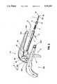
- FIG. 1is a side view of a first embodiment of the invention with its trigger in a forward cocked position.
- FIG. 2is an exploded perspective view of the punch of FIG. 1.
- FIG. 3is a left side elevational view in section of the punch of FIG. 1.
- FIG. 4is a perspective view of a first modification of the portion A in FIG. 3.
- FIG. 5is a perspective view of a second modification of the portion A in FIG. 3.
- FIG. 6is a left side elevational view of the left side wall of the punch along line 5--5 of FIG. 2.
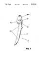
- FIG. 7is a side elevational view of the trigger of the first embodiment.
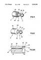
- FIG. 8is a right side elevational view, in section, of the blade pusher barrel of the first embodiment.
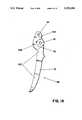
- FIG. 9is a side elevational view, in section, of the blade drum of the first embodiment.
- FIG. 10is a side elevational view of the punch mandrel of the first embodiment.
- FIG. 11is a top view of the mandrel of FIG. 10.
- FIG. 12is a side elevational view in section of a second embodiment of the punch of FIG. 1.
- FIG. 13is an exploded perspective view of embodiment of FIG. 12.
- FIG. 14is a right side elevational view of the trigger of the second embodiment of the invention.
- FIG. 15is a right side elevational view in section of the blade pusher barrel of the second embodiment of the invention.
- FIG. 16is a top view in section of the blade pusher barrel of the punch of FIG. 12.
- FIG. 17is a sectional view of the blade pusher barrel of the punch of FIG. 12 along line 17--17 of FIG. 16.
- FIG. 18is a sectional view of the blade pusher barrel of the punch of FIG. 12 along line 18--18 of FIG. 16.
- FIG. 19is a sectional view of the blade pusher barrel of the punch of FIG. 12 along line 19--19 of FIG. 16.
- FIG. 20is a side elevational view in section of a third embodiment of the punch of FIG. 1.
- FIG. 21is an exploded perspective view of the embodiment of FIG. 20.
- FIG. 22is a right side elevational view of the trigger of the punch of FIG. 20.
- FIG. 23is a side elevational view in section of a fourth embodiment of the punch of FIG. 1.
- FIG. 24is a side elevational view, in section, of a modification of the blade drum of FIG. 9.
- the vascular punchdesignated by the numeral 1
- a pistol-like, closed, hollow housing 10comprising a proximal, or rear, pistol-like handle portion 20 and a distal, or front, portion 21.
- the housingalso comprises left 10a and right 10b side walls and a flange-like wall 33 (not shown) therebetween at the periphery of the housing from its proximal end to a distal or front opening 32.
- the punch 1further comprises a trigger 3 comprising an upper portion 36, illustrated in FIGS.
- the punch 1further comprises a blade drum 6 and a punch mandrel 7, as illustrated in FIG. 2. The distal ends of the drum 6 and mandrel 7, as shown in FIGS. 2 and 3, extend distally outside of the housing 10 through the front opening 32 therein.
- punch 1further comprises a blade pusher barrel 4, a restraining pin 9 and a spring 5.
- FIG. 2also illustrates the left 10a, and right 10b, side walls of the housing 10 as well as their associated flange-like portions 33a and 33b (not shown) which combine, on assembly of the punch, to form the flange-like wall 33.
- the wall 33which extends from the rear of the housing 10, around its periphery, and terminates at the distal opening 32 and separates the side walls from each other.
- FIGS. 2 and 3there are also shown means 28a on the inner surface of the left side wall 10a for aligning the two side walls, by coupling said alignment means with complementary means 28b (not shown) on the inner surface of the right side wall 10b during assembly of the punch 1.
- These alignment meanscomprise at least one pin 28a extending normally from the inner surface of the proximal portion 20a of the left side wall 10a and an equal number of complementary cavities 28b (not shown) on the inner surface of the right side wall 10b to receive said pin or pins.
- the alignment pinsmay be on the right side wall 10b and the cavities on the left side wall 10a.
- Other alignment meansas well known in the art, may be used in lieu of the above.
- the left side wall 10a inner surfacefurther comprises pivot means 29, as shown in FIGS. 2, 3 and 6, for engaging complementary means 35 in the upper portion 36 of the trigger 3 in a pivotal manner.
- the means 29consists of a cylindrical pin near the distal portion of a lower opening 27a in flange-like wall portion 33a, of the left side wall 10a, at the lower juncture of the proximal 20a and distal 21a portions thereof.
- Side wall 10bcomprises a similar opening 27b in flange-like wall portion 33b.
- the openings 27a and 27bcombine to form lower opening 27, in the housing 10, when the punch is assembled.
- said means 29may be on the inner surface of the right rather than the left side wall of the housing 10.
- the pivoting meansmay comprise two pins extending normally from the side walls of the trigger and complementary holes or cavities in the side walls of the housing to receive said pins.
- the side walls of the housing 10comprise, in their distal sections, cavities 31a, in the left side wall, and 31b (not shown) in the right side wall, to receive the restraining pin 9 which has been passed through mandrel 7 to render it immobile during use of the punch.
- the distal portion 21 of the housing 10also comprises a cavity (not shown), to receive the blade pusher barrel 4.
- Trigger 3shown in FIGS. 2, 3, and 7, comprises front 42a, rear 42b and right 42c and left 42d (not shown) side walls and upper 36 and 37 portions.
- the lower portion 37comprises a trigger arm for effecting proximal movement of the trigger 3 from its distal 3a to its proximal 3b (dashed lines) position as shown in FIG. 1.
- the trigger upper portion 36comprises a port 35 therethrough, to engage the pivot pin 29, when the punch is assembled, and allow the trigger 3 to pivot thereabout when the trigger arm 37 is moved proximally during formation of the opening in the blood vessel.
- the blade pusher barrel 4shown in FIGS. 2, 3 and 8, comprises an elongated cylindrical body comprising at its distal end, a cavity comprising a distal portion 52, terminated by a distal opening 43, and a proximal portion 51 terminated by a proximal wall 47.
- the inner wall 44 of the cavity portion 52has an inner diameter slightly greater than the inner diameter of the inner wall 45 of the cavity portion 51.
- Proximal wall portion 45is terminated, where it joins wall portion 44, by a flat wall 53 normal to wall 44.
- the right and left side walls of blade pusher barrel 4,further comprise elongated slots 46a and 46b (not shown), respectively, spaced proximally from wall 53.
- Spring 5shown in FIGS. 2 & 3, is inserted into cavity portion 51 wherein it is restrained by the restraining pin 9, shown in FIGS. 2 and 3, which has been passed through slots 46a and 46b and received by cavities 31a and 31b of housing 10.
- the hollow blade drum 6, shown in FIGS. 3 and 9,comprises an elongated hollow cylinder comprising an outer wall 63, a lumen 65, a rear wall 62, a proximal opening 64 and a distal hollow truncated conical blade portion 61 terminated by an opening 60.
- the blade drumis inserted into distal cavity portion 52 of the barrel 4 until its rear wall 62 abuts wall portion 53 thereof.
- the outer diameter of the blade drum outer wall 63is slightly less than the inner diameter of the barrel cavity portion 52.
- the blade portioncomprises a serrated knife-edge blade 61a.
- the blade portioncomprises a smooth knife-edged blade 61b.
- the blade portioncomprises a flat face 67, which joins the inner surface 68 of the drum at its distal end at an angle of about 90° (i.e., within standard tolerances) to create a sharp cutting edge 69.
- the diameter of the disc of the mandrelis less than the inner diameter of the blade drum.
- the distal end of the blade drumcomprises a hollow cylindrical portion 72 whose front end comprises a flat face 75 which joins the inner surface 74 of the cylindrical portion 72 at an angle of about 90° to form a sharp cutting edge 75.
- the punch mandrel 7, shown in FIGS. 1-5, 10 and 11,is inserted into the blade pusher barrel 4 through the hollow portion 65 of the blade drum 6, the proximal end of the mandrel 7 extending beyond the rear wall 62 of the blade drum 6 into the hollow portion of the spring.
- the inner diameter of the blade drum cavity 65is slightly greater than the outer diameter of the mandrel so that the mandrel may pass therethrough.
- the distal end of mandrel 7further comprises a reduced diameter stem 55 terminated by a circular disc 56.
- the discmay have an outer diameter greater than the inner diameter of the blade drum lumen 65, if the disc is to serve as an anvil. Alternatively, the outer diameter of the disc may be less than the inner diameter of the lumen if the disc is to enter the lumen during the hole forming process.
- blade portion 61, of the blade drum 6will extend distally from opening 32 of the housing 10. It will, however, be spaced proximally from the reduced stem 55 and circular disc 56 of mandrel 7.
- the disc 56may comprise a distal portion 57 comprising a distally tapered truncated cone to facilitate insertion of the disc into the blood vessel.
- an incisionis made in the blood vessel the length of the incision being smaller than the diameter of the hole to be made therein, and the disc inserted, by means of conical portion 57 (if present) into, the vessel.
- the proximal side of the circular disc 56is pulled against the inner wall of the vessel.
- Pressureis then applied to the trigger arm 37 causing the trigger arm to move proximally toward the handle portion 20 of the housing and pivot about pivot pin 29 whereby trigger upper portion 36 is caused to rotate distally and forward as shown by the arrow B in FIGS. 2, 3 and 7.
- the restraining pin 9prevents movement of the mandrel 7, while blade drum 6 moves forward, thereby causing the reduced stem 55 with its associated tissue sample to be positioned within the cavity 65 in blade drum 6.
- the slots 46a and 46balso move forward causing restraining pin 9 to be positioned at the proximal end of the slots.
- Spring 5is, consequently, compressed between the rear wall 47 of barrel cavity portion 51 and restraining pin 9. After the hole has been formed in the blood vessel, and pressure on the trigger arm 37 removed, spring 5 expands causing blade pusher barrel 4 and blade drum 6 to move proximally and the trigger arm 37 to move distally. Reduced stem portion 55, of mandrel 7, is then exposed permitting removal of the tissue sample therefrom.
- trigger 3Bas best seen in FIG. 14, comprises a second hole 34, therethrough, between the side walls 42c and 42d in its upper portion 36.
- the hole 34will receive a complementary engaging pin 70 on a modification 4B of the blade pusher barrel 4.
- blade pusher barrel 4Bas best seen in FIGS.
- 15-19comprises, at its proximal end, a shelf 71 extending proximally and normally therefrom.
- a cylindrical pin 70to link the blade pusher barrel 4 to the trigger 3B, through the hole 34 therein, extends normally from said shelf 71.
- a third embodiment, designated 1C in FIG. 20, of the inventionwhich provides means for locking the trigger in its proximal, or retracted, position as a consequence of which the reduced stem 55 of the mandrel 7, and the tissue sample, are retained within the lumen 65 of the blade drum 6 until the trigger is intentionally released.
- the trigger 3Cmay be locked into a retracted proximal position, as illustrated in FIG. 1, by the dashed lines 3b, through engagement of locking means thereon with complementary locking means in the housing 10.
- the housing 10also comprises an upper port through which rigger release means may enter to unlock the trigger 3C when it is in the retracted, locked position 3b.
- trigger 3Ccomprises an arm 38, coplanar with the side walls 42c and 42d thereof, which descends, and is separated by a notch 41, from the upper part of the rear wall 42b of the trigger 3C.
- a protrusion 39having an angular side wall 39a and bottom flat face 40, which can lockingly engage with complementary locking means of the housing 10, extends from and is coplanar with arm 38.
- the distal rotation of trigger upper portion 36causes arm extension 39 to move upward along a complementary angular wall 24 (not shown) of locking means 23 (not shown) on the flange-like wall 33 (not shown) of the housing 10 thereby causing notch 41 to close.
- Trigger arm 37 of trigger 3Ccannot be caused to involuntarily move distally. Consequently, blade drum 6 cannot be retracted and the distal end of the mandrel 7 with the tissue sample attached to the reduced stem 55 thereof will not extend beyond the opening 60 of blade drum 6. Thus, the tissue sample cannot fall off and is protected until its recovery is desired.
- the angular wall 24 and upper face 25 of the locking means 25 and the flange like wall 33 of the housingare formed from their corresponding parts, e.g., angular wall portions 24a and 24b (not shown) on the right and left side walls 10a and 10b, respectively, of the housing.
- trigger release meanssuch as the tip 66 of a cap 8, as shown in FIG. 20, is inserted through upper port 26 of the housing until it engages arm 38.
- arm 38engages arm 38.
- notch 41closes.
- Spring 5expands causing blade pusher barrel 4 and blade drum 6 to move proximally while the trigger arm 37 of trigger 3C moves distally.
- Reduced stem portion 55, of mandrel 7,is then exposed permitting removal of the tissue sample therefrom.
- the release meanscomprises an cantilever type tab 77, as seen in FIG.
- the tab 77may be an integrally molded part of the housing. The tab 77 can be pressed downward thereby releasing the locking means by compressing the notch 41 and causing the locking arm 38, on the trigger, and the complementary protrusion 23 of the housing to disengage.
- Other release meansas known in the art, may be used in lieu of the above indicated means.
- the vascular punch 1 of the first embodimentfurther comprises the trigger - blade pusher barrel linking combination of the second embodiment and the trigger locking and release features of the third embodiment.
- all of the partsact in the same manner, as described above, as similarly designated parts in the other embodiments.
Landscapes
- Health & Medical Sciences (AREA)
- Life Sciences & Earth Sciences (AREA)
- Surgery (AREA)
- Molecular Biology (AREA)
- Engineering & Computer Science (AREA)
- Biomedical Technology (AREA)
- Heart & Thoracic Surgery (AREA)
- Medical Informatics (AREA)
- Nuclear Medicine, Radiotherapy & Molecular Imaging (AREA)
- Animal Behavior & Ethology (AREA)
- General Health & Medical Sciences (AREA)
- Public Health (AREA)
- Veterinary Medicine (AREA)
- Surgical Instruments (AREA)
- Instructional Devices (AREA)
- Prostheses (AREA)
Abstract
Description
This is a continuation-in-part of Ser. No. 07/345,995 filed May 2, 1989, now abandoned.
The present invention relates to surgical instruments. More particularly it relates to a vascular punch, for forming uniform openings in body vessels such as aortae, having decreased manual force requirements and providing for safe retention of the removed vessel tissue.
In cardiac surgery it is often necessary to connect tubular items with blood vessels such as arteries and veins. Numerous prior art instruments for that purpose have been described, e.g., in U.S. Pat. Nos. 3,776,237 and 4,018,228.
The prior art instruments suffer, inter alia, from the following disadvantages:
1) large manual forces required to cut through the vessels; and
2) difficulty in stabilization of the instrument to form uniform smooth openings.
U.S. Pat. No. 4,018,228, for instance, describes an instrument comprising an elongated hollow sleeve and an elongated rod, extending through one end of the hollow sleeve and reciprocally movable therein. The elongated rod has a distal narrowed end portion comprising a fixed cylindrical blade while the hollow sleeve has a hollow cylindrical blade removably attached thereto. The sliding rod is activated by a handle attached normally thereto and extending through the slots in the elongated sleeve to move the rod proximally and pull the blade thereon into the hollow sleeve thereby forming an opening in the vessel tissue therebetween. The hollow sleeve further contains a spring proximal to the handle of the rod which is compressed during proximal movement of the. After punching the hole into the vessel, pressure on the handle is removed and the spring expands causing the front of the rod, its associated cylindrical blade and tissue sample to exit from the hollow sleeve.
By virtue of the form of the instrument it is difficult to stabilize it in a constant alignment with the blood vessel. Accordingly, the instrument will change its alignment during its use resulting in poorly defined openings. It is also necessary that large manual forces be applied to the handle of the elongated rod to overcome the pressure of the spring and cut through the vessel wall. This will cause greater or lesser difficulties in accordance the strength of the user.
It has now been found that the above indicated problems may be overcome by use of the punch of the instant invention.
It is an object of the invention to provide a surgical instrument, to form openings in blood vessels, having an increased mechanical advantage which reduces the manual force requirements.
Another object of the invention is to provide an instrument, as described above, wherein the manual pressure is applied normally to the punch axis thereby stabilizing the punch tip during activation.
Yet another object of the invention is to provide an instrument wherein the removed tissue sample is retained therein for recovery when needed.
According to another object of the invention there is provided a punch wherein the blade has radial serrations to reduce the required cutting force.
These and other objects of the invention will be in part apparent from, and in part suggested by, the detailed description in conjunction with the accompanying drawings.
Throughout this application the terms proximal and rear will be used to refer to points toward or near the user and far or away from the patient and the terms distal or front will be used to refer to points far or away from the user and toward or near the patient.
The invention is best described in the following detailed description with reference to the drawings, wherein like numbers refer to like parts, in which
FIG. 1 is a side view of a first embodiment of the invention with its trigger in a forward cocked position.
FIG. 2 is an exploded perspective view of the punch of FIG. 1.
FIG. 3 is a left side elevational view in section of the punch of FIG. 1.
FIG. 4 is a perspective view of a first modification of the portion A in FIG. 3.
FIG. 5 is a perspective view of a second modification of the portion A in FIG. 3.
FIG. 6 is a left side elevational view of the left side wall of the punch along line 5--5 of FIG. 2.
FIG. 7 is a side elevational view of the trigger of the first embodiment.
FIG. 8 is a right side elevational view, in section, of the blade pusher barrel of the first embodiment.
FIG. 9 is a side elevational view, in section, of the blade drum of the first embodiment.
FIG. 10 is a side elevational view of the punch mandrel of the first embodiment.
FIG. 11 is a top view of the mandrel of FIG. 10.
FIG. 12 is a side elevational view in section of a second embodiment of the punch of FIG. 1.
FIG. 13 is an exploded perspective view of embodiment of FIG. 12.
FIG. 14 is a right side elevational view of the trigger of the second embodiment of the invention.
FIG. 15 is a right side elevational view in section of the blade pusher barrel of the second embodiment of the invention.
FIG. 16 is a top view in section of the blade pusher barrel of the punch of FIG. 12.
FIG. 17 is a sectional view of the blade pusher barrel of the punch of FIG. 12 alongline 17--17 of FIG. 16.
FIG. 18 is a sectional view of the blade pusher barrel of the punch of FIG. 12 alongline 18--18 of FIG. 16.
FIG. 19 is a sectional view of the blade pusher barrel of the punch of FIG. 12 alongline 19--19 of FIG. 16.
FIG. 20 is a side elevational view in section of a third embodiment of the punch of FIG. 1.
FIG. 21 is an exploded perspective view of the embodiment of FIG. 20.
FIG. 22 is a right side elevational view of the trigger of the punch of FIG. 20.
FIG. 23 is a side elevational view in section of a fourth embodiment of the punch of FIG. 1.
FIG. 24 is a side elevational view, in section, of a modification of the blade drum of FIG. 9.
Referring to FIGS. 1-11 the vascular punch, designated by thenumeral 1, comprises a pistol-like, closed,hollow housing 10 comprising a proximal, or rear, pistol-like handle portion 20 and a distal, or front, portion 21. The housing also comprises left 10a and right 10b side walls and a flange-like wall 33 (not shown) therebetween at the periphery of the housing from its proximal end to a distal orfront opening 32. Thepunch 1 further comprises a trigger 3 comprising anupper portion 36, illustrated in FIGS. 2, 3 and 7, within thehousing 10 and a lower portion, or trigger arm, 37 which extends outside of thehousing 10 through alower port 27, therein, situated at the lower juncture between the proximal 20 and distal 21 sections ofhousing 10. Thetrigger arm 37 may occupy two positions, a distal cocked position 3a and a retracted proximal position, illustrated by the dashed lines 3b in FIG. 1. Thepunch 1 further comprises ablade drum 6 and apunch mandrel 7, as illustrated in FIG. 2. The distal ends of thedrum 6 andmandrel 7, as shown in FIGS. 2 and 3, extend distally outside of thehousing 10 through the front opening 32 therein.
As shown in FIGS. 2 and 3punch 1 further comprises a blade pusher barrel 4, a restrainingpin 9 and a spring 5. FIG. 2 also illustrates the left 10a, and right 10b, side walls of thehousing 10 as well as their associated flange-like portions 33a and 33b (not shown) which combine, on assembly of the punch, to form the flange-like wall 33. Thewall 33 which extends from the rear of thehousing 10, around its periphery, and terminates at thedistal opening 32 and separates the side walls from each other.
In FIGS. 2 and 3 there are also shown means 28a on the inner surface of the left side wall 10a for aligning the two side walls, by coupling said alignment means with complementary means 28b (not shown) on the inner surface of the right side wall 10b during assembly of thepunch 1. These alignment means comprise at least one pin 28a extending normally from the inner surface of the proximal portion 20a of the left side wall 10a and an equal number of complementary cavities 28b (not shown) on the inner surface of the right side wall 10b to receive said pin or pins. If desired, the alignment pins may be on the right side wall 10b and the cavities on the left side wall 10a. Other alignment means, as well known in the art, may be used in lieu of the above.
The left side wall 10a inner surface further comprises pivot means 29, as shown in FIGS. 2, 3 and 6, for engagingcomplementary means 35 in theupper portion 36 of the trigger 3 in a pivotal manner. The means 29 consists of a cylindrical pin near the distal portion of a lower opening 27a in flange-like wall portion 33a, of the left side wall 10a, at the lower juncture of the proximal 20a and distal 21a portions thereof. Side wall 10b comprises a similar opening 27b in flange-like wall portion 33b. The openings 27a and 27b combine to formlower opening 27, in thehousing 10, when the punch is assembled. If desired, however, said means 29 may be on the inner surface of the right rather than the left side wall of thehousing 10. If desired, the pivoting means (not shown) may comprise two pins extending normally from the side walls of the trigger and complementary holes or cavities in the side walls of the housing to receive said pins. In addition, the side walls of thehousing 10 comprise, in their distal sections, cavities 31a, in the left side wall, and 31b (not shown) in the right side wall, to receive therestraining pin 9 which has been passed throughmandrel 7 to render it immobile during use of the punch.
The distal portion 21 of thehousing 10 also comprises a cavity (not shown), to receive the blade pusher barrel 4.
Trigger 3, shown in FIGS. 2, 3, and 7, comprises front 42a, rear 42b and right 42c and left 42d (not shown) side walls and upper 36 and 37 portions. Thelower portion 37 comprises a trigger arm for effecting proximal movement of the trigger 3 from its distal 3a to its proximal 3b (dashed lines) position as shown in FIG. 1.
In addition, the triggerupper portion 36 comprises aport 35 therethrough, to engage thepivot pin 29, when the punch is assembled, and allow the trigger 3 to pivot thereabout when thetrigger arm 37 is moved proximally during formation of the opening in the blood vessel.
The blade pusher barrel 4, shown in FIGS. 2, 3 and 8, comprises an elongated cylindrical body comprising at its distal end, a cavity comprising adistal portion 52, terminated by adistal opening 43, and aproximal portion 51 terminated by aproximal wall 47.
Theinner wall 44 of thecavity portion 52 has an inner diameter slightly greater than the inner diameter of theinner wall 45 of thecavity portion 51.
Spring 5, shown in FIGS. 2 & 3, is inserted intocavity portion 51 wherein it is restrained by the restrainingpin 9, shown in FIGS. 2 and 3, which has been passed through slots 46a and 46b and received by cavities 31a and 31b ofhousing 10.
Thehollow blade drum 6, shown in FIGS. 3 and 9, comprises an elongated hollow cylinder comprising anouter wall 63, alumen 65, arear wall 62, aproximal opening 64 and a distal hollow truncatedconical blade portion 61 terminated by anopening 60. The blade drum is inserted intodistal cavity portion 52 of the barrel 4 until itsrear wall 62 abutswall portion 53 thereof. The outer diameter of the blade drumouter wall 63 is slightly less than the inner diameter of thebarrel cavity portion 52.
In one aspect of this embodiment, illustrated in FIG. 4, the blade portion comprises a serrated knife-edge blade 61a. In a second aspect of this embodiment, as illustrated in FIG. 5, the blade portion comprises a smooth knife-edged blade 61b. In yet another modification, as seen in FIG. 9, the blade portion comprises a flat face 67, which joins the inner surface 68 of the drum at its distal end at an angle of about 90° (i.e., within standard tolerances) to create a sharp cutting edge 69. In this modification the diameter of the disc of the mandrel is less than the inner diameter of the blade drum.
In another modification of the blade drum, as illustrated in FIG. 24, wherein the diameter of the disc of the mandrel is less than the inner diameter of the blade drum, the distal end of the blade drum comprises a hollowcylindrical portion 72 whose front end comprises aflat face 75 which joins theinner surface 74 of thecylindrical portion 72 at an angle of about 90° to form asharp cutting edge 75.
Thepunch mandrel 7, shown in FIGS. 1-5, 10 and 11, is inserted into the blade pusher barrel 4 through thehollow portion 65 of theblade drum 6, the proximal end of themandrel 7 extending beyond therear wall 62 of theblade drum 6 into the hollow portion of the spring. The inner diameter of theblade drum cavity 65 is slightly greater than the outer diameter of the mandrel so that the mandrel may pass therethrough.
The distal end ofmandrel 7 further comprises a reduced diameter stem 55 terminated by acircular disc 56. The disc may have an outer diameter greater than the inner diameter of theblade drum lumen 65, if the disc is to serve as an anvil. Alternatively, the outer diameter of the disc may be less than the inner diameter of the lumen if the disc is to enter the lumen during the hole forming process.
After assembly of the punch, with the trigger 3 in its distal, cocked position, as seen in FIGS. 2 and 3,blade portion 61, of theblade drum 6, will extend distally from opening 32 of thehousing 10. It will, however, be spaced proximally from the reducedstem 55 andcircular disc 56 ofmandrel 7. If desired, thedisc 56 may comprise adistal portion 57 comprising a distally tapered truncated cone to facilitate insertion of the disc into the blood vessel.
In the practice of using the vascular punch, of the invention, an incision is made in the blood vessel the length of the incision being smaller than the diameter of the hole to be made therein, and the disc inserted, by means of conical portion 57 (if present) into, the vessel. The proximal side of thecircular disc 56 is pulled against the inner wall of the vessel. Pressure is then applied to thetrigger arm 37 causing the trigger arm to move proximally toward the handle portion 20 of the housing and pivot aboutpivot pin 29 whereby triggerupper portion 36 is caused to rotate distally and forward as shown by the arrow B in FIGS. 2, 3 and 7.
As theupper portion 36 of trigger 3 rotates in the direction of arrow B the front face 42a thereof moves forward thereby causing blade pusher barrel 4, whoserear wall 50 abuts the front face 42a of the trigger 3, to move forward wherebyblade drum 6 is pushed forward, until theopening 60 of theblade drum 6 abuts the outer wall of the blood vessel opposite thecircular disc 56 ofmandrel 7. Continued retraction oftrigger arm 37 of trigger 3 causesblade 61 to cut a portion out of the vessel and pass over the mandrel reducedstem 55 andcircular disc 56 when the inner diameter of the drum is greater than the outer diameter of the disc. After the piece has been cut out it remains on the reducedstem 55 ofmandrel 7. The restrainingpin 9 prevents movement of themandrel 7, whileblade drum 6 moves forward, thereby causing the reducedstem 55 with its associated tissue sample to be positioned within thecavity 65 inblade drum 6. As blade pusher barrel 4 moves forward the slots 46a and 46b also move forward causing restrainingpin 9 to be positioned at the proximal end of the slots. Spring 5 is, consequently, compressed between therear wall 47 ofbarrel cavity portion 51 and restrainingpin 9. After the hole has been formed in the blood vessel, and pressure on thetrigger arm 37 removed, spring 5 expands causing blade pusher barrel 4 andblade drum 6 to move proximally and thetrigger arm 37 to move distally.Reduced stem portion 55, ofmandrel 7, is then exposed permitting removal of the tissue sample therefrom.
It is sometimes desirable to more accurately control the movement of the blade pusher barrel to prevent misalignment thereof when it is caused to move distally, during the hole forming process, or proximally, after forming the hole. This is accomplished by the second embodiment, designated 1B and illustrated in FIGS. 12-19, of the invention wherein the punch further comprises means for interconnecting the trigger and blade pusher barrel. Thus, trigger 3B, as best seen in FIG. 14, comprises asecond hole 34, therethrough, between the side walls 42c and 42d in itsupper portion 36. Thehole 34 will receive a complementaryengaging pin 70 on amodification 4B of the blade pusher barrel 4. In this modificationblade pusher barrel 4B, as best seen in FIGS. 15-19, comprises, at its proximal end, ashelf 71 extending proximally and normally therefrom. Acylindrical pin 70, to link the blade pusher barrel 4 to thetrigger 3B, through thehole 34 therein, extends normally from saidshelf 71. When the barrel and trigger are thusly linked theproximal wall 50 of the barrel abuts the front face 42a of theupper portion 36 of thetrigger 3B.
It is, also, often desirable to retain the tissue sample removed from the blood vessel when an opening is formed therein by use of a vascular punch. However, a disadvantage of the prior art punches, which is also present in the above embodiment and modifications of this invention, is the possibility of loss of the tissue samples, from the blood vessels, when the triggers spring back.
That disadvantage is overcome by a third embodiment, designated 1C in FIG. 20, of the invention which provides means for locking the trigger in its proximal, or retracted, position as a consequence of which the reducedstem 55 of themandrel 7, and the tissue sample, are retained within thelumen 65 of theblade drum 6 until the trigger is intentionally released.
In this embodiment, as illustrated in FIGS. 20 and 21, thetrigger 3C may be locked into a retracted proximal position, as illustrated in FIG. 1, by the dashed lines 3b, through engagement of locking means thereon with complementary locking means in thehousing 10. Thehousing 10 also comprises an upper port through which rigger release means may enter to unlock thetrigger 3C when it is in the retracted, locked position 3b.
As best seen in FIG. 22trigger 3C comprises anarm 38, coplanar with the side walls 42c and 42d thereof, which descends, and is separated by anotch 41, from the upper part of the rear wall 42b of thetrigger 3C. Aprotrusion 39, having an angular side wall 39a and bottomflat face 40, which can lockingly engage with complementary locking means of thehousing 10, extends from and is coplanar witharm 38. The distal rotation of triggerupper portion 36, during cutting of the hole in the blood vessel, causesarm extension 39 to move upward along a complementary angular wall 24 (not shown) of locking means 23 (not shown) on the flange-like wall 33 (not shown) of thehousing 10 thereby causingnotch 41 to close. At the greatest extent of proximal retraction of thetrigger arm 37 oftrigger 3C, the lower end ofarm 38 passes the upper end of locking means 23 and notch 41 springs open causingface 40 onarm 38 and the upper face 25 (not shown) of the locking means 23, onhousing 10, to lockingly engage.Trigger arm 37 oftrigger 3C, therefore, cannot be caused to involuntarily move distally. Consequently,blade drum 6 cannot be retracted and the distal end of themandrel 7 with the tissue sample attached to the reducedstem 55 thereof will not extend beyond theopening 60 ofblade drum 6. Thus, the tissue sample cannot fall off and is protected until its recovery is desired. Theangular wall 24 andupper face 25 of the locking means 25 and the flange likewall 33 of the housing are formed from their corresponding parts, e.g., angular wall portions 24a and 24b (not shown) on the right and left side walls 10a and 10b, respectively, of the housing.
When removal of the tissue sample is desired trigger release means, such as thetip 66 of a cap 8, as shown in FIG. 20, is inserted throughupper port 26 of the housing until it engagesarm 38. Continued downward pressure of thetip 66 causesarm 38 to move toward thetrigger 3Cbody forcing notch 41 to close. Upon closure ofnotch 41 the complementary locking means on thetrigger 3C andhousing 10 disengage. Spring 5 then expands causing blade pusher barrel 4 andblade drum 6 to move proximally while thetrigger arm 37 oftrigger 3C moves distally.Reduced stem portion 55, ofmandrel 7, is then exposed permitting removal of the tissue sample therefrom. In a most preferred embodiment the release means comprises ancantilever type tab 77, as seen in FIG. 23, on the top of the housing and attached to theport 26 at itsdistal side wall 78. If desired, thetab 77 may be an integrally molded part of the housing. Thetab 77 can be pressed downward thereby releasing the locking means by compressing thenotch 41 and causing the lockingarm 38, on the trigger, and thecomplementary protrusion 23 of the housing to disengage. Other release means, as known in the art, may be used in lieu of the above indicated means.
In a fourth embodiment, designated 1D and illustrated in FIG. 23, thevascular punch 1 of the first embodiment further comprises the trigger - blade pusher barrel linking combination of the second embodiment and the trigger locking and release features of the third embodiment. In this embodiment all of the parts act in the same manner, as described above, as similarly designated parts in the other embodiments.
Changes may be affected with respect to the details of construction and use of the invention without departing from the spirit and scope thereof as defined in the appended claims.
Claims (34)
1. A vascular punch for cutting openings in blood vessels comprising a pistol-shaped housing having an opening at the front end thereof; a blade drum provided at said opening of said housing; a punch mandrel having an end thereof passing through said opening in said housing; a trigger having an arm pivot means for pivoting said trigger on said housing,
said housing having port means through which said trigger arm of said trigger can extend outwardly; restraining means in said housing for engaging said punch mandrel; and blade pusher barrel means movably mounted between said trigger and said blade drum, said trigger further comprising a lower portion extending outside of said housing; and an upper portion residing within said housing comprising means for transferring motion to said blade pusher barrel means, said blade pusher barrel means being axially and reciprocally movable within barrel receiving means of said housing, and comprising an elongated cylindrical body comprising means for receiving motion transferred from the upper portion of said trigger, cavity means to contain said blade drum and said punch mandrel, opposing elongated longitudinal slots through which said punch mandrel restraining means passes to engage said punch mandrel, said punch mandrel further comprising an elongated cylindrical rod having a transverse hole therethrough to receive said punch mandrel restraining means and a reduced stem at its distal end terminated by a circular mandrel disc normal thereto, said blade drum comprising a hollow cylindrical body having a longitudinal lumen for passage of said punch mandrel therethrough; and blade means for cooperating with said circular disc of said punch mandrel to form said opening in the blood vessel, said restraining means preventing movement of said punch mandrel when said blade pusher barrel means and said blade drum move axially and reciprocally; and restoring means for restoring said trigger to a normal position after use.
2. A punch of claim 1, wherein said housing comprises
a. pistol shaped side walls;
b. means for aligning said side walls during assembly; and
c. pivot means, comprising a pin normal to, and on the inner surface of, one of said side walls, to engage complementary pivoting means on the trigger.
3. The punch of claim 1, wherein the upper portion of said trigger comprises
1) a hole passing therethrough, from one side wall to the other, to engage said pivot means of said housing around which said trigger may pivot; and
2) a front wall which abuts the rear wall of said blade pusher barrel.
4. The punch of claim 1, wherein said blade pusher barrel comprises an elongated cylindrical body comprising:
a. a front end having a cavity; comprising
1) a port at its front end;
2) a distal hollow section to receive said blade drum;
3) a proximal hollow section, adjacent said distal hollow section, to receive said spring means and having an inner diameter which is less than the inner diameter of said distal hollow section; and
4) a rear wall; and
b. a rear end comprising
1) a wall perpendicular to the longitudinal axis of the barrel;
2) two opposing longitudinal slots through the walls of said proximal hollow section adjacent said distal hollow section, through which said restraining pin passes; and
3) a flat wall at, and normal to, said front end of the proximal hollow section which abut said rear wall of said blade drum.
5. The punch of claim 1, wherein the outer diameter of said mandrel disc is slightly less than the inner diameter of said blade drum.
6. The punch of claim 1, wherein the outer diameter of said mandrel disc is slightly greater than the inner diameter of said blade drum.
7. The punch of claim 1, wherein the front portion of said blade drum comprises a truncated cone the distal portion of which forms said blade.
8. The punch of claim 7, wherein said blade is a serrated-edged knife blade.
9. The punch of claim 7, wherein said blade is a smooth bevel-edged knife blade.
10. The punch of claim 7, wherein the front wall of said blade drum comprises a flat face which joins the inner surface of said drum at an angle of about 90 degrees to form a sharp cutting edge.
11. The punch of claim 1, further comprising complementary locking means on said housing and trigger for releasably locking said trigger arm in its proximal, retracted position whereby said reduced stem of said punch mandrel, with its associated circular disc, is retained within said blade drum cavity, and releasing means to cause said complementary locking means to disengage.
12. The punch of claim 11, wherein said complementary locking means on said trigger comprises an arm, descending from a rear wall of the upper part of the trigger, coplanar with the side walls, the lower portion of said arm being separated from said rear wall of the trigger by a compressible notch, said arm further comprising means to lockingly engage complementary means on said housing and releasing means to selectively and manually compress said locking arm notch thereby urging said complementary locking means to move apart and become disengaged.
13. The punch of claim 12, wherein said releasing means comprises
a. an upper port in said housing adjacent said locking arm of said trigger; and
b. an article which may be passed through said port to press upon said locking arm and compress said notch,
14. The punch of claim 12, wherein said releasing means comprises a molded portion of said upper housing wall adjacent said locking arm of said trigger which can be depressed, whereby it can press on said trigger locking arm and thereby compress said notch.
15. A vascular punch, for cutting openings in blood vessels, comprising:
a. a substantially closed pistol-shaped housing comprising:
1) two pistol shaped side walls, each comprising a pistol grip shaped descending proximal section and an approximately horizontal barrel shaped distal section;
2) a flange-like wall, extending normally to and peripherally around the edges of said side walls from the proximal end of the housing to a distal end thereof;
3) an opening at said distal end through which a punch mandrel and a blade drum pass through;
4) a lower port, near a lower juncture of said proximal and distal sections thereof, through which a trigger passes through;
5) pivot means around which an upper portion of said trigger may rotate;
6) two matching cavities, in said side walls, spaced from said front opening of said housing, engaging a restraining pin which passes through slots in a blade pusher barrel and a transverse hole in said punch mandrel;
7) matching cavities in said distal section of said side walls which combine to form a cavity in the assembled housing to receive said blade pusher barrel;
8) at least one pin normal to the inner surface of one side wall, extending from said side wall into said housing; and
9) at least one complementary cavity on the inner surface of the other side wall to receive said at least one pin for alignment and coupling to form the assembled housing;
b. said trigger comprising;
1) a lower portion forming a trigger arm, extending outwardly from said housing;
2) an upper portion residing within said housing comprising;
a) front, rear and side walls;
b) means complementary to said pivot means in the housing around which said trigger may pivot,
said front wall of said trigger abutting against a rear wall of said blade pusher barrel; and
c) said blade pusher barrel, being axially movable within said housing, and comprising an elongated cylindrical body comprising;
1) at its front end a cavity comprising;
a) a front opening;
b) a distal hollow section to receive said blade drum; and
c) a proximal hollow section, adjacent said distal hollow section, whose inner diameter is less than the inner diameter of said distal hollow section;
2) a wall at its rear end perpendicular to the longitudinal axis of said barrel;
3) two opposing longitudinal slots through the walls of the proximal hollow section, adjacent its junction with the distal hollow section, through which said restraining pin passes; and
4) a flat wall at, and normal to, said distal end of said proximal hollow section to abut the rear wall of said blade drum;
d) said punch mandrel comprising an elongated cylindrical rod comprising;
1) hole therethrough spaced distally from said proximal end to receive said restraining pin;
2) a reduced stem at its distal end terminated distally by a circular disc normal thereto;
e) said blade drum means comprising a hollow cylindrical rod comprising;
1) a longitudinal concentric lumen for passage of the punch mandrel therethrough;
2) blade means to cooperate with said circular disc of said punch mandrel to form a hole in a blood vessel; and
3) at its proximal end, a flat rear wall perpendicular to the longitudinal axis of said rod, wherein the outer diameter of said wall is slightly greater than the inner diameter of said proximal cavity portion, and slightly less than the inner diameter of said distal cavity portion, of said blade pusher barrel;
f) said restraining pin comprising an elongated cylindrical rod whose outer diameter is slightly less than the inner diameter of aid transverse hole in the rear end of said punch mandrel; and
g) spring means inserted in said proximal portion of said cavity of said blade pusher barrel and restrained therein by said restraining pin passing through said punch mandrel.
16. The punch of claim 15, wherein said blade means comprises a distal truncated cone.
17. The punch of claim 16, wherein said blade means comprises a smooth knife-edged blade.
18. The punch of claim 6, wherein said blade means comprises a serrated blade.
19. The punch of claim 16, wherein the front wall of said blade drum comprises a flat face which joins the inner surface of said drum at an angle of about 90 degrees to form a sharp cutting edge.
20. The punch of claim 15, further comprising locking means in said housing for lockingly engaging complementary means on the side arm of the upper portion of said trigger when said trigger arm is in its proximal position, said blade drum extending outside of said housing and said reduced stem and circular disc of said punch mandrel is retained in said blade drum lumen and trigger releasing means for selectively and manually compressing said trigger arm notch, thereby urging said complementary locking means to move apart and become disengaged.
21. The punch of claim 20, wherein said locking means on said trigger comprises an arm, descending from the rear wall of the upper part of said trigger, coplanar with said side walls, the lower portion of said arm being separated from said rear wall of said trigger by a compressible notch, said arm further comprising means to lockingly engage complementary means on said housing.
22. The punch of claim 21, wherein said trigger releasing means comprises
a) an upper port in said housing adjacent said locking arm of said trigger; and
b) an article which may be passed through said port to press upon said locking arm and compress said notch.
23. The punch of claim 21, wherein said releasing means comprises a molded portion of the upper housing wall adjacent said locking arm of said trigger which can be depressed, whereby said molded portion presses on said trigger locking arm to thereby compress said notch.
24. The punch of claim 15, wherein said circular disc terminating the front end of said punch mandrel has a larger outer diameter than the inner diameter of said blade drum.
25. The punch of claim 15, wherein said circular disc terminating the front end of said punch mandrel has a smaller outer diameter than the inner diameter of said blade drum.
26. The punch of claim 15, further comprising linking means for linking said blade pusher barrel to said trigger.
27. The punch of claim 26, wherein said linking means comprises
a) a shelf whose top surface is coplanar with said trigger side walls, extending proximally from said rear wall of the blade pusher barrel, said shelf further comprising an elongated pin extending normally from said top surface to engage complementary means on said trigger; and
b) a hole on said trigger upper portion, extending therethrough from one side wall, to engage said pin.
28. The punch of claim 15, wherein the pivoting means
a) on said housing comprises a pin attached to the inner surface of one side wall of said housing extending approximately normally into the housing around which the upper portion of the trigger may rotate; and
b) on said trigger comprises a hole to engage said pin.
29. The punch of claim 15, wherein said pivoting means
a) on said trigger comprises at least one pin extending normally from at least one side wall thereof; and
b) on said housing comprises at least an equal number of complementary pin receiving means in the side walls thereof.
30. The punch of claim 1, further comprising linking means for linking said blade pusher barrel to said trigger.
31. The punch of claim 30, wherein said linking means comprises
a) a shelf whose top surface is coplanar with said trigger side walls, extending proximally from the rear wall of said blade pusher barrel, said shelf further comprising an elongated pin extending normally from said top surface to engage complementary means on said trigger; and
b) a hole on said trigger upper portion, extending therethrough from one side wall, to engage said pin.
32. The punch of claim 1, wherein said pivoting means
a) on the housing comprises a pin attached to the inner surface of one side wall of said housing extending approximately normally into said housing around which the upper portion of the trigger may rotate; and
b) on said trigger comprises a hole to engage said pin.
33. The punch of claim 1, wherein said pivoting means
a) on said trigger comprises at least one pin extending normally from at least one side wall thereof; and
b) on said housing comprises at least an equal number of complementary pin receiving means in the side walls thereof.
34. The punch of claim 1, wherein the front portion of said blade drum comprises a cylinder, the inner diameter of which is greater than the diameter of said mandrel disc, and whose distal face joins the inner surface of the drum at an angle 90 degrees to form a sharp cutting edge.
Priority Applications (8)
| Application Number | Priority Date | Filing Date | Title |
|---|---|---|---|
| US07/711,656US5192294A (en) | 1989-05-02 | 1991-06-06 | Disposable vascular punch |
| AU16208/92AAU644570B2 (en) | 1991-06-06 | 1992-05-13 | Disposable vascular punch |
| TW081103749ATW209165B (en) | 1991-06-06 | 1992-05-14 | |
| CA002070465ACA2070465C (en) | 1991-06-06 | 1992-06-04 | Disposable vascular punch |
| DE69204355TDE69204355D1 (en) | 1991-06-06 | 1992-06-05 | Vascular punches for single use. |
| EP92109557AEP0517252B1 (en) | 1991-06-06 | 1992-06-05 | Disposable vascular punch |
| MX9202687AMX9202687A (en) | 1991-06-06 | 1992-06-05 | DISPOSABLE VASCULAR DRILL. |
| JP14568892AJP3172843B2 (en) | 1991-06-06 | 1992-06-05 | Disposable vascular punch |
Applications Claiming Priority (2)
| Application Number | Priority Date | Filing Date | Title |
|---|---|---|---|
| US34599589A | 1989-05-02 | 1989-05-02 | |
| US07/711,656US5192294A (en) | 1989-05-02 | 1991-06-06 | Disposable vascular punch |
Related Parent Applications (1)
| Application Number | Title | Priority Date | Filing Date |
|---|---|---|---|
| US34599589AContinuation-In-Part | 1989-05-02 | 1989-05-02 |
Publications (1)
| Publication Number | Publication Date |
|---|---|
| US5192294Atrue US5192294A (en) | 1993-03-09 |
Family
ID=24858977
Family Applications (1)
| Application Number | Title | Priority Date | Filing Date |
|---|---|---|---|
| US07/711,656Expired - LifetimeUS5192294A (en) | 1989-05-02 | 1991-06-06 | Disposable vascular punch |
Country Status (8)
| Country | Link |
|---|---|
| US (1) | US5192294A (en) |
| EP (1) | EP0517252B1 (en) |
| JP (1) | JP3172843B2 (en) |
| AU (1) | AU644570B2 (en) |
| CA (1) | CA2070465C (en) |
| DE (1) | DE69204355D1 (en) |
| MX (1) | MX9202687A (en) |
| TW (1) | TW209165B (en) |
Cited By (113)
| Publication number | Priority date | Publication date | Assignee | Title |
|---|---|---|---|---|
| US5403338A (en)* | 1992-01-21 | 1995-04-04 | Scanlan International, Inc. | Punch for opening passages between two compartments |
| USD372310S (en) | 1995-06-30 | 1996-07-30 | Pilling Weck Incorporated | Surgical punch |
| US5611352A (en)* | 1995-09-14 | 1997-03-18 | Kobren; Myles S. | Cervical biopsy device |
| WO1998042262A1 (en) | 1997-03-26 | 1998-10-01 | Perclose, Inc. | Device and method for suturing tissue |
| US5827316A (en)* | 1997-06-05 | 1998-10-27 | Atrion Medical Products, Inc. | Rotating aortic punch |
| EP0916314A1 (en) | 1997-11-17 | 1999-05-19 | Fehling, Ulrike | Vascular punch |
| US5910153A (en)* | 1996-12-04 | 1999-06-08 | Aesculap Ag & Co. Kg | Surgical punch |
| US6022367A (en)* | 1997-06-18 | 2000-02-08 | United States Surgical | Surgical apparatus for forming a hole in a blood vessel |
| US6036710A (en)* | 1996-10-04 | 2000-03-14 | United States Surgical | Apparatus for formation of a hole in a blood vessel |
| US6080176A (en)* | 1998-10-30 | 2000-06-27 | Atrion Medical Products, Inc. | Medical punch with high shear angle cutting edges |
| US6190396B1 (en) | 1999-09-14 | 2001-02-20 | Perclose, Inc. | Device and method for deploying and organizing sutures for anastomotic and other attachments |
| US20010004698A1 (en)* | 1999-04-16 | 2001-06-21 | Blatter Duane D. | Locking compression plate anastomosis apparatus |
| US20010018592A1 (en)* | 1999-03-01 | 2001-08-30 | Laurent Schaller | Bridge clip tissue connector apparatus and methods |
| US6340354B1 (en)* | 1996-05-17 | 2002-01-22 | Christopher L Rambin | Automated compulsory blood extraction system |
| US6355050B1 (en) | 1992-12-10 | 2002-03-12 | Abbott Laboratories | Device and method for suturing tissue |
| US6358258B1 (en) | 1999-09-14 | 2002-03-19 | Abbott Laboratories | Device and method for performing end-to-side anastomosis |
| US20020087046A1 (en)* | 1997-04-23 | 2002-07-04 | St. Jude Medical Cardiovascular Group, Inc. | Medical grafting methods and apparatus |
| US20020087181A1 (en)* | 1996-11-07 | 2002-07-04 | St. Jude Medical Cardiovascular Group, Inc. | Medical grafting methods and apparatus |
| WO2002047532A3 (en)* | 2000-12-11 | 2002-09-26 | By Pass Inc | Method and apparatus for forming apertures in blood vessels |
| US20020188302A1 (en)* | 1998-11-06 | 2002-12-12 | St. Jude Medical Atg, Inc. | Minimally invasive revascularization apparatus and methods |
| US20030014064A1 (en)* | 1999-04-16 | 2003-01-16 | Blatter Duane D. | Anvil apparatus for anastomosis and related methods and systems |
| WO2003009742A2 (en) | 2001-07-25 | 2003-02-06 | Rkl Technologies, Inc. | Actuating handle for a surgical instrument |
| US6517553B2 (en) | 1993-11-08 | 2003-02-11 | Abbott Laboratories | Device and method for suturing of internal puncture sites |
| WO2003030753A1 (en)* | 2001-10-05 | 2003-04-17 | Genzyme Corporation | Surgical punch device |
| US6551334B2 (en) | 1999-04-16 | 2003-04-22 | Integrated Vascular Interventional Technologies, Lc | Externally directed anastomosis systems and externally positioned anastomosis fenestra cutting apparatus |
| US6558399B1 (en) | 2000-06-30 | 2003-05-06 | Abbott Laboratories | Devices and method for handling a plurality of suture elements during a suturing procedure |
| US20030093093A1 (en)* | 1999-03-04 | 2003-05-15 | Modesitt D. Bruce | Articulating suturing device and method |
| US20030120291A1 (en)* | 2001-12-26 | 2003-06-26 | Chin Albert K. | Temporary seal and method for facilitating anastomosis |
| US6626921B2 (en) | 1999-04-16 | 2003-09-30 | Integrated Vascular Interventional Technologies, L.C. | Externally positioned anvil apparatus for cutting anastomosis |
| US20030191481A1 (en)* | 2000-03-31 | 2003-10-09 | John Nguyen | Multiple bias surgical fastener |
| US20030195531A1 (en)* | 1998-06-03 | 2003-10-16 | Barry Gardiner | Tissue connector apparatus and methods |
| US20030204198A1 (en)* | 1998-01-28 | 2003-10-30 | St. Jude Medical Atg, Inc. | Vessel cutting devices |
| US20030208214A1 (en)* | 2000-03-20 | 2003-11-06 | Amir Loshakove | Anastomotic connector and graft expander for mounting a graft |
| US6652542B2 (en) | 1999-04-16 | 2003-11-25 | Integrated Vascular Interventional Technologies, L.C. (Ivit, Lc) | External anastomosis operators and related systems for anastomosis |
| US6695859B1 (en) | 1999-04-05 | 2004-02-24 | Coalescent Surgical, Inc. | Apparatus and methods for anastomosis |
| US20040049221A1 (en)* | 1998-05-29 | 2004-03-11 | By-Pass, Inc. | Method and apparatus for forming apertures in blood vessels |
| US20040054303A1 (en)* | 2002-07-29 | 2004-03-18 | Taylor Geoffrey L. | Blanching response pressure sore detector apparatus and method |
| US20040068276A1 (en)* | 2002-10-04 | 2004-04-08 | Steve Golden | Anastomosis apparatus and methods |
| US20040073247A1 (en)* | 1998-05-29 | 2004-04-15 | By-Pass, Inc. | Method and apparatus for forming apertures in blood vessels |
| US6726694B2 (en) | 1999-04-16 | 2004-04-27 | Integrated Vascular Interventional Technologies, L.C. (Ivit, Lc) | Intraluminally directed anvil apparatus and related methods and systems |
| US6726704B1 (en) | 1998-05-29 | 2004-04-27 | By-Pass, Inc. | Advanced closure device |
| US6730103B2 (en) | 1997-05-19 | 2004-05-04 | Pepi Dakov | Connector system and methods for cutting and joining hollow anatomical structures |
| US6730102B1 (en) | 2000-11-06 | 2004-05-04 | Abbott Laboratories | Systems, devices and methods for deploying needles |
| US20040087985A1 (en)* | 1999-03-19 | 2004-05-06 | Amir Loshakove | Graft and connector delivery |
| US20040092998A1 (en)* | 2001-10-18 | 2004-05-13 | Kevin Sniffin | Anastomosis instrument and method for performing same |
| US20040092977A1 (en)* | 1999-05-18 | 2004-05-13 | Cardica, Inc. | Sutureless closure and deployment system for connecting blood vessels |
| US20040097973A1 (en)* | 2000-03-20 | 2004-05-20 | Amir Loshakove | Transvascular bybass method and system |
| US20040098011A1 (en)* | 1999-05-18 | 2004-05-20 | Cardica, Inc. | Method for cutting tissue |
| US20040097978A1 (en)* | 1999-03-04 | 2004-05-20 | Modesitt D. Bruce | Articulating suturing device and method |
| US6743244B2 (en) | 1999-04-16 | 2004-06-01 | Integrated Vascular Interventional Technologies, L.C. | Soft anvil apparatus for cutting anastomosis fenestra |
| US20040103900A1 (en)* | 2002-12-03 | 2004-06-03 | Melker Jeremy S. | Tracheotomy surgical device |
| US20040111099A1 (en)* | 2000-10-10 | 2004-06-10 | Coalescent Surgical, Inc. | Minimally invasive valve repair procedure and apparatus |
| US20040167550A1 (en)* | 1999-05-18 | 2004-08-26 | Cardica, Inc. | Integrated anastomosis tool with graft vessel attachment device and cutting device |
| US20040225306A1 (en)* | 1999-12-14 | 2004-11-11 | Blatter Duane D. | Paired expandable anastomosis devices |
| US20040225313A1 (en)* | 2003-05-09 | 2004-11-11 | Kanner Rowland W. | Tissue punch and method for creating an anastomosis for locating a bypass graft |
| US20050004591A1 (en)* | 2002-01-22 | 2005-01-06 | Bender Theodore M. | Tool for creating an opening in tissue |
| US20050033330A1 (en)* | 2002-01-23 | 2005-02-10 | Cardica, Inc. | Method of performing anastomosis |
| US20050038456A1 (en)* | 2002-01-22 | 2005-02-17 | Cardica, Inc. | Anastomosis device having a deployable section |
| US20050043749A1 (en)* | 2003-08-22 | 2005-02-24 | Coalescent Surgical, Inc. | Eversion apparatus and methods |
| US20050059982A1 (en)* | 2003-09-11 | 2005-03-17 | Michael Zung | Articulating suturing device and method |
| US20050065601A1 (en)* | 2002-04-18 | 2005-03-24 | Coalescent Surgical, Inc. | Annuloplasty apparatus and methods |
| US20050070923A1 (en)* | 2003-09-26 | 2005-03-31 | Mcintosh Scott A. | Device and method for suturing intracardiac defects |
| US20050075667A1 (en)* | 1999-03-01 | 2005-04-07 | Laurent Schaller | Tissue connector apparatus and methods |
| US20050075659A1 (en)* | 2003-03-30 | 2005-04-07 | Fidel Realyvasquez | Apparatus and methods for minimally invasive valve surgery |
| US20050101983A1 (en)* | 1998-05-29 | 2005-05-12 | By-Pass,Inc. | Method and apparatus for forming apertures in blood vessels |
| US20050143761A1 (en)* | 1999-03-04 | 2005-06-30 | Modesitt D. B. | Articulating suturing device and method |
| US20050149065A1 (en)* | 2003-12-19 | 2005-07-07 | Modesitt D. B. | Device and method for suturing of internal puncture sites |
| US20050171561A1 (en)* | 1992-12-10 | 2005-08-04 | Songer Ronald W. | Device and method for suturing tissue |
| US6979338B1 (en) | 1998-05-29 | 2005-12-27 | By-Pass Inc. | Low profile anastomosis connector |
| US20060030869A1 (en)* | 2002-11-14 | 2006-02-09 | By-Pass, Inc. | Adhesive anastomosis connection system |
| US7022131B1 (en) | 1998-05-29 | 2006-04-04 | By-Pass Inc. | Methods and devices for vascular surgery |
| US7029481B1 (en) | 2000-11-06 | 2006-04-18 | Abbott Laboratories | Systems, devices and methods for suturing patient tissue |
| US7063711B1 (en) | 1998-05-29 | 2006-06-20 | By-Pass, Inc. | Vascular surgery |
| US20060142785A1 (en)* | 1999-03-04 | 2006-06-29 | Modesitt D B | Articulating suturing device and method |
| US20060206124A1 (en)* | 1996-07-23 | 2006-09-14 | Keith Milliman | Anastomosis instrument and method for performing same |
| US20060293701A1 (en)* | 2001-05-02 | 2006-12-28 | Medtronic, Inc. | Self-closing surgical clip for tissue |
| US20060289601A1 (en)* | 2003-05-30 | 2006-12-28 | Tyco Healthcare Group, Lp | End-to-end anastomosis instrument and method for performing same |
| US20070032799A1 (en)* | 2005-08-08 | 2007-02-08 | Pantages Anthony J | Vascular suturing device |
| US20070062999A1 (en)* | 2002-05-31 | 2007-03-22 | Orban Joseph P Iii | End-to end anastomosis instrument and method for performing same |
| US20070142848A1 (en)* | 2003-07-25 | 2007-06-21 | Stephen Ainsworth | Sealing clip, delivery systems, and methods |
| US20070173868A1 (en)* | 1997-04-23 | 2007-07-26 | St. Jude Medical Atg, Inc. | Medical grafting connectors and fasteners |
| US7258694B1 (en) | 2002-06-17 | 2007-08-21 | Origin Medsystems, Inc. | Medical punch and surgical procedure |
| US20080045979A1 (en)* | 2006-08-18 | 2008-02-21 | Abbott Laboratories | Articulating suture device and method |
| US20080147114A1 (en)* | 1998-05-29 | 2008-06-19 | Bypass, Inc. | Vascular port device |
| US20080249546A1 (en)* | 2007-01-05 | 2008-10-09 | Sandstrom Jeffrey D | Anastomosis systems and methods |
| US20090138033A1 (en)* | 2007-02-12 | 2009-05-28 | Blake Iii Joseph W | Aortic punch |
| US20090264903A1 (en)* | 2008-03-10 | 2009-10-22 | Medtronic, Inc. | Apparatus and methods for minimally invasive valve repair |
| US7763040B2 (en) | 1998-06-03 | 2010-07-27 | Medtronic, Inc. | Tissue connector apparatus and methods |
| US7842049B2 (en) | 2002-12-31 | 2010-11-30 | Abbott Laboratories | Systems for anchoring a medical device in a body lumen |
| US7879047B2 (en) | 2003-12-10 | 2011-02-01 | Medtronic, Inc. | Surgical connection apparatus and methods |
| US7963973B2 (en) | 1998-06-03 | 2011-06-21 | Medtronic, Inc. | Multiple loop tissue connector apparatus and methods |
| US7976556B2 (en) | 2002-09-12 | 2011-07-12 | Medtronic, Inc. | Anastomosis apparatus and methods |
| US8012164B1 (en) | 2002-01-22 | 2011-09-06 | Cardica, Inc. | Method and apparatus for creating an opening in the wall of a tubular vessel |
| US8048108B2 (en) | 2005-08-24 | 2011-11-01 | Abbott Vascular Inc. | Vascular closure methods and apparatuses |
| US8083754B2 (en) | 2005-08-08 | 2011-12-27 | Abbott Laboratories | Vascular suturing device with needle capture |
| US8267947B2 (en) | 2005-08-08 | 2012-09-18 | Abbott Laboratories | Vascular suturing device |
| US20130012977A1 (en)* | 2011-06-15 | 2013-01-10 | Empire Technology Development Llc | Punch tool |
| US8377082B2 (en) | 2003-01-14 | 2013-02-19 | Medtronic, Inc. | Methods and apparatus for making precise incisions in body vessels |
| US8394114B2 (en) | 2003-09-26 | 2013-03-12 | Medtronic, Inc. | Surgical connection apparatus and methods |
| US8419753B2 (en) | 2003-12-23 | 2013-04-16 | Abbott Laboratories | Suturing device with split arm and method of suturing tissue |
| US8518060B2 (en) | 2009-04-09 | 2013-08-27 | Medtronic, Inc. | Medical clip with radial tines, system and method of using same |
| US8529583B1 (en) | 1999-09-03 | 2013-09-10 | Medtronic, Inc. | Surgical clip removal apparatus |
| US8574244B2 (en) | 2007-06-25 | 2013-11-05 | Abbott Laboratories | System for closing a puncture in a vessel wall |
| US8663252B2 (en) | 2010-09-01 | 2014-03-04 | Abbott Cardiovascular Systems, Inc. | Suturing devices and methods |
| US8668704B2 (en) | 2009-04-24 | 2014-03-11 | Medtronic, Inc. | Medical clip with tines, system and method of using same |
| US8858573B2 (en) | 2012-04-10 | 2014-10-14 | Abbott Cardiovascular Systems, Inc. | Apparatus and method for suturing body lumens |
| US8864778B2 (en) | 2012-04-10 | 2014-10-21 | Abbott Cardiovascular Systems, Inc. | Apparatus and method for suturing body lumens |
| US8920442B2 (en) | 2005-08-24 | 2014-12-30 | Abbott Vascular Inc. | Vascular opening edge eversion methods and apparatuses |
| US9241707B2 (en) | 2012-05-31 | 2016-01-26 | Abbott Cardiovascular Systems, Inc. | Systems, methods, and devices for closing holes in body lumens |
| US9370353B2 (en) | 2010-09-01 | 2016-06-21 | Abbott Cardiovascular Systems, Inc. | Suturing devices and methods |
| US9456811B2 (en) | 2005-08-24 | 2016-10-04 | Abbott Vascular Inc. | Vascular closure methods and apparatuses |
| US20170333067A1 (en)* | 2014-10-31 | 2017-11-23 | Rutgers, The State University Of New Jersey | Transection device |
| US10426449B2 (en) | 2017-02-16 | 2019-10-01 | Abbott Cardiovascular Systems, Inc. | Articulating suturing device with improved actuation and alignment mechanisms |
Families Citing this family (12)
| Publication number | Priority date | Publication date | Assignee | Title |
|---|---|---|---|---|
| FR2712183B1 (en)* | 1993-11-10 | 1996-01-12 | Moria Sa | Hole punch type surgical instrument for eye surgery. |
| EP0901393B1 (en) | 1996-04-26 | 2003-12-10 | Medtronic, Inc. | Intravascular balloon occlusion device and vessel punch member |
| US6461320B1 (en) | 1998-08-12 | 2002-10-08 | Cardica, Inc. | Method and system for attaching a graft to a blood vessel |
| US6206913B1 (en) | 1998-08-12 | 2001-03-27 | Vascular Innovations, Inc. | Method and system for attaching a graft to a blood vessel |
| US7048751B2 (en) | 2001-12-06 | 2006-05-23 | Cardica, Inc. | Implantable medical device such as an anastomosis device |
| AU5143000A (en) | 1999-05-18 | 2000-12-05 | Vascular Innovations, Inc. | Implantable medical device such as an anastomosis device |
| US6776785B1 (en) | 2000-10-12 | 2004-08-17 | Cardica, Inc. | Implantable superelastic anastomosis device |
| US6471713B1 (en) | 2000-11-13 | 2002-10-29 | Cardica, Inc. | System for deploying an anastomosis device and method of performing anastomosis |
| US6554764B1 (en) | 2000-11-13 | 2003-04-29 | Cardica, Inc. | Graft vessel preparation device and methods for using the same |
| US7585306B2 (en) | 2003-12-24 | 2009-09-08 | Maquet Cardiovascular Llc | Anastomosis device, tools and methods of using |
| US8162963B2 (en) | 2004-06-17 | 2012-04-24 | Maquet Cardiovascular Llc | Angled anastomosis device, tools and method of using |
| CN108514441B (en)* | 2018-04-28 | 2024-06-18 | 美茵(北京)医疗器械研发有限公司 | Blood vessel punching assembly and puncher |
Citations (6)
| Publication number | Priority date | Publication date | Assignee | Title |
|---|---|---|---|---|
| US2818852A (en)* | 1956-06-27 | 1958-01-07 | Heinz W Kugler | Spring-pressed surgical instrument |
| US3776237A (en)* | 1972-05-11 | 1973-12-04 | Tecna Corp | Surgical tool and method of providing a surgical opening |
| US3835860A (en)* | 1973-06-21 | 1974-09-17 | H Garretson | Surgical bone punch |
| US3837345A (en)* | 1973-08-31 | 1974-09-24 | A Matar | Venous valve snipper |
| US4018228A (en)* | 1975-02-24 | 1977-04-19 | Goosen Carl C | Surgical punch apparatus |
| US4733663A (en)* | 1986-07-02 | 1988-03-29 | Farley Daniel K | Medical instrument for removing bone |
Family Cites Families (5)
| Publication number | Priority date | Publication date | Assignee | Title |
|---|---|---|---|---|
| US3104666A (en) | 1962-11-02 | 1963-09-24 | Myron T Hale | Surgical instrument for performing a tracheotomy |
| US4216776A (en)* | 1978-05-19 | 1980-08-12 | Thoratec Laboratories Corporation | Disposable aortic perforator |
| US4423730A (en)* | 1982-03-01 | 1984-01-03 | Shelhigh Inc. | Atriotomy button and implantation device |
| US4951860A (en)* | 1987-12-28 | 1990-08-28 | Edward Weck & Co. | Method and apparatus for storing, dispensing and applying surgical staples |
| DE9100873U1 (en)* | 1991-01-25 | 1991-04-18 | Wisap Gesellschaft für wissenschaftlichen Apparatebau mbH, 8029 Sauerlach | Round tube morcellator |
- 1991
- 1991-06-06USUS07/711,656patent/US5192294A/ennot_activeExpired - Lifetime
- 1992
- 1992-05-13AUAU16208/92Apatent/AU644570B2/ennot_activeExpired
- 1992-05-14TWTW081103749Apatent/TW209165B/zhnot_activeIP Right Cessation
- 1992-06-04CACA002070465Apatent/CA2070465C/ennot_activeExpired - Lifetime
- 1992-06-05MXMX9202687Apatent/MX9202687A/enunknown
- 1992-06-05DEDE69204355Tpatent/DE69204355D1/ennot_activeExpired - Lifetime
- 1992-06-05JPJP14568892Apatent/JP3172843B2/ennot_activeExpired - Lifetime
- 1992-06-05EPEP92109557Apatent/EP0517252B1/ennot_activeExpired - Lifetime
Patent Citations (6)
| Publication number | Priority date | Publication date | Assignee | Title |
|---|---|---|---|---|
| US2818852A (en)* | 1956-06-27 | 1958-01-07 | Heinz W Kugler | Spring-pressed surgical instrument |
| US3776237A (en)* | 1972-05-11 | 1973-12-04 | Tecna Corp | Surgical tool and method of providing a surgical opening |
| US3835860A (en)* | 1973-06-21 | 1974-09-17 | H Garretson | Surgical bone punch |
| US3837345A (en)* | 1973-08-31 | 1974-09-24 | A Matar | Venous valve snipper |
| US4018228A (en)* | 1975-02-24 | 1977-04-19 | Goosen Carl C | Surgical punch apparatus |
| US4733663A (en)* | 1986-07-02 | 1988-03-29 | Farley Daniel K | Medical instrument for removing bone |
Cited By (252)
| Publication number | Priority date | Publication date | Assignee | Title |
|---|---|---|---|---|
| US5403338A (en)* | 1992-01-21 | 1995-04-04 | Scanlan International, Inc. | Punch for opening passages between two compartments |
| US6036699A (en)* | 1992-12-10 | 2000-03-14 | Perclose, Inc. | Device and method for suturing tissue |
| US6355050B1 (en) | 1992-12-10 | 2002-03-12 | Abbott Laboratories | Device and method for suturing tissue |
| US7445626B2 (en) | 1992-12-10 | 2008-11-04 | Abbott Laboratories | Device and method for suturing tissue |
| US20050171561A1 (en)* | 1992-12-10 | 2005-08-04 | Songer Ronald W. | Device and method for suturing tissue |
| US6517553B2 (en) | 1993-11-08 | 2003-02-11 | Abbott Laboratories | Device and method for suturing of internal puncture sites |
| USD372310S (en) | 1995-06-30 | 1996-07-30 | Pilling Weck Incorporated | Surgical punch |
| US5611352A (en)* | 1995-09-14 | 1997-03-18 | Kobren; Myles S. | Cervical biopsy device |
| US5800362A (en)* | 1995-09-14 | 1998-09-01 | Kobren; Myles S. | Cervical biopsy device |
| US6340354B1 (en)* | 1996-05-17 | 2002-01-22 | Christopher L Rambin | Automated compulsory blood extraction system |
| US20060206124A1 (en)* | 1996-07-23 | 2006-09-14 | Keith Milliman | Anastomosis instrument and method for performing same |
| US7635385B2 (en) | 1996-07-23 | 2009-12-22 | Keith Milliman | Anastomosis instrument and method for performing same |
| US6036710A (en)* | 1996-10-04 | 2000-03-14 | United States Surgical | Apparatus for formation of a hole in a blood vessel |
| US20020087181A1 (en)* | 1996-11-07 | 2002-07-04 | St. Jude Medical Cardiovascular Group, Inc. | Medical grafting methods and apparatus |
| US7578829B2 (en) | 1996-11-07 | 2009-08-25 | St. Jude Medical Atg, Inc. | Medical grafting methods and apparatus |
| US20040116946A1 (en)* | 1996-11-07 | 2004-06-17 | St. Jude Medical Atg, Inc. | Medical grafting methods and apparatus |
| DE19650204C2 (en)* | 1996-12-04 | 2000-09-21 | Aesculap Ag & Co Kg | Surgical punch |
| US5910153A (en)* | 1996-12-04 | 1999-06-08 | Aesculap Ag & Co. Kg | Surgical punch |
| WO1998042262A1 (en) | 1997-03-26 | 1998-10-01 | Perclose, Inc. | Device and method for suturing tissue |
| US20070173868A1 (en)* | 1997-04-23 | 2007-07-26 | St. Jude Medical Atg, Inc. | Medical grafting connectors and fasteners |
| US7850705B2 (en) | 1997-04-23 | 2010-12-14 | St. Jude Medical Atg, Inc. | Medical grafting connectors and fasteners |
| US20020087046A1 (en)* | 1997-04-23 | 2002-07-04 | St. Jude Medical Cardiovascular Group, Inc. | Medical grafting methods and apparatus |
| US6730103B2 (en) | 1997-05-19 | 2004-05-04 | Pepi Dakov | Connector system and methods for cutting and joining hollow anatomical structures |
| US5827316A (en)* | 1997-06-05 | 1998-10-27 | Atrion Medical Products, Inc. | Rotating aortic punch |
| EP0882429A1 (en) | 1997-06-05 | 1998-12-09 | Atrion Medical Products, Inc. | "Rotating aortic punch" |
| US6022367A (en)* | 1997-06-18 | 2000-02-08 | United States Surgical | Surgical apparatus for forming a hole in a blood vessel |
| DE19750803C2 (en)* | 1997-11-17 | 2000-04-06 | Fehling Ulrike | Vascular punch |
| EP0916314A1 (en) | 1997-11-17 | 1999-05-19 | Fehling, Ulrike | Vascular punch |
| DE19750803A1 (en)* | 1997-11-17 | 1999-06-02 | Fehling Ulrike | Vascular punch |
| US20030204198A1 (en)* | 1998-01-28 | 2003-10-30 | St. Jude Medical Atg, Inc. | Vessel cutting devices |
| US20040049218A1 (en)* | 1998-01-28 | 2004-03-11 | Berg Todd Allen | Vessel cutting devices |
| US8382784B2 (en) | 1998-01-28 | 2013-02-26 | St. Jude Medical Atg, Inc. | Vessel cutting devices |
| US20080039882A1 (en)* | 1998-01-28 | 2008-02-14 | St. Jude Medical Atg, Inc. | Vessel cutting devices |
| US20050101983A1 (en)* | 1998-05-29 | 2005-05-12 | By-Pass,Inc. | Method and apparatus for forming apertures in blood vessels |
| US20040049221A1 (en)* | 1998-05-29 | 2004-03-11 | By-Pass, Inc. | Method and apparatus for forming apertures in blood vessels |
| US6726704B1 (en) | 1998-05-29 | 2004-04-27 | By-Pass, Inc. | Advanced closure device |
| US7063711B1 (en) | 1998-05-29 | 2006-06-20 | By-Pass, Inc. | Vascular surgery |
| US20040073247A1 (en)* | 1998-05-29 | 2004-04-15 | By-Pass, Inc. | Method and apparatus for forming apertures in blood vessels |
| US20080147114A1 (en)* | 1998-05-29 | 2008-06-19 | Bypass, Inc. | Vascular port device |
| US7022131B1 (en) | 1998-05-29 | 2006-04-04 | By-Pass Inc. | Methods and devices for vascular surgery |
| US6979338B1 (en) | 1998-05-29 | 2005-12-27 | By-Pass Inc. | Low profile anastomosis connector |
| US20030195531A1 (en)* | 1998-06-03 | 2003-10-16 | Barry Gardiner | Tissue connector apparatus and methods |
| US7963973B2 (en) | 1998-06-03 | 2011-06-21 | Medtronic, Inc. | Multiple loop tissue connector apparatus and methods |
| US7763040B2 (en) | 1998-06-03 | 2010-07-27 | Medtronic, Inc. | Tissue connector apparatus and methods |
| US7547313B2 (en) | 1998-06-03 | 2009-06-16 | Medtronic, Inc. | Tissue connector apparatus and methods |
| US6080176A (en)* | 1998-10-30 | 2000-06-27 | Atrion Medical Products, Inc. | Medical punch with high shear angle cutting edges |
| US20020188302A1 (en)* | 1998-11-06 | 2002-12-12 | St. Jude Medical Atg, Inc. | Minimally invasive revascularization apparatus and methods |
| US7722643B2 (en) | 1999-03-01 | 2010-05-25 | Medtronic, Inc. | Tissue connector apparatus and methods |
| US8353921B2 (en) | 1999-03-01 | 2013-01-15 | Medtronic, Inc | Tissue connector apparatus and methods |
| US20050075667A1 (en)* | 1999-03-01 | 2005-04-07 | Laurent Schaller | Tissue connector apparatus and methods |
| US8118822B2 (en) | 1999-03-01 | 2012-02-21 | Medtronic, Inc. | Bridge clip tissue connector apparatus and methods |
| US20010018592A1 (en)* | 1999-03-01 | 2001-08-30 | Laurent Schaller | Bridge clip tissue connector apparatus and methods |
| US7892255B2 (en) | 1999-03-01 | 2011-02-22 | Medtronic, Inc. | Tissue connector apparatus and methods |
| US8663248B2 (en) | 1999-03-04 | 2014-03-04 | Abbott Laboratories | Articulating suturing device and method |
| US6964668B2 (en) | 1999-03-04 | 2005-11-15 | Abbott Laboratories | Articulating suturing device and method |
| US7837696B2 (en) | 1999-03-04 | 2010-11-23 | Abbott Laboratories | Articulating suturing device and method |
| US7842047B2 (en) | 1999-03-04 | 2010-11-30 | Abbott Laboratories | Articulating suturing device and method |
| US20090157105A1 (en)* | 1999-03-04 | 2009-06-18 | Abbott Laboratories | Articulating suturing device and method |
| US7846170B2 (en) | 1999-03-04 | 2010-12-07 | Abbott Laboratories | Articulating suturing device and method |
| US20040097978A1 (en)* | 1999-03-04 | 2004-05-20 | Modesitt D. Bruce | Articulating suturing device and method |
| US8172860B2 (en) | 1999-03-04 | 2012-05-08 | Abbott Laboratories | Articulating suturing device and method |
| US7850701B2 (en) | 1999-03-04 | 2010-12-14 | Abbott Laboratories | Articulating suturing device and method |
| US20110066184A1 (en)* | 1999-03-04 | 2011-03-17 | Abbott Laboratories | Articulating suturing device and method |
| US20030093093A1 (en)* | 1999-03-04 | 2003-05-15 | Modesitt D. Bruce | Articulating suturing device and method |
| US20110071567A1 (en)* | 1999-03-04 | 2011-03-24 | Abbott Laboratories | Articulating suturing and device and method |
| US20110077670A1 (en)* | 1999-03-04 | 2011-03-31 | Abbott Laboratories | Articulating suturing device and method |
| US7235087B2 (en) | 1999-03-04 | 2007-06-26 | Abbott Park | Articulating suturing device and method |
| US9993237B2 (en) | 1999-03-04 | 2018-06-12 | Abbott Laboratories | Articulating suturing device and method |
| US8323298B2 (en) | 1999-03-04 | 2012-12-04 | Abbott Laboratories | Articulating suturing device and method |
| US20060142785A1 (en)* | 1999-03-04 | 2006-06-29 | Modesitt D B | Articulating suturing device and method |
| US7001400B1 (en) | 1999-03-04 | 2006-02-21 | Abbott Laboratories | Articulating suturing device and method |
| US9301747B2 (en) | 1999-03-04 | 2016-04-05 | Abbott Laboratories | Articulating suturing device and method |
| US8038688B2 (en) | 1999-03-04 | 2011-10-18 | Abbott Laboratories | Articulating suturing device and method |
| US9282960B2 (en) | 1999-03-04 | 2016-03-15 | Abbott Laboratories | Articulating suturing device and method |
| US20050143761A1 (en)* | 1999-03-04 | 2005-06-30 | Modesitt D. B. | Articulating suturing device and method |
| US8057491B2 (en) | 1999-03-04 | 2011-11-15 | Abbott Laboratories | Articulating suturing device and method |
| US8048092B2 (en) | 1999-03-04 | 2011-11-01 | Abbott Laboratories | Articulating suturing device and method |
| US20040087985A1 (en)* | 1999-03-19 | 2004-05-06 | Amir Loshakove | Graft and connector delivery |
| US6695859B1 (en) | 1999-04-05 | 2004-02-24 | Coalescent Surgical, Inc. | Apparatus and methods for anastomosis |
| US20110184442A1 (en)* | 1999-04-05 | 2011-07-28 | Medtronic, Inc. | Apparatus and Methods for Anastomosis |
| US8211131B2 (en) | 1999-04-05 | 2012-07-03 | Medtronic, Inc. | Apparatus and methods for anastomosis |
| US7938840B2 (en) | 1999-04-05 | 2011-05-10 | Medtronic, Inc. | Apparatus and methods for anastomosis |
| US20040102797A1 (en)* | 1999-04-05 | 2004-05-27 | Coalescent Surgical, Inc. | Apparatus and methods for anastomosis |
| US6726694B2 (en) | 1999-04-16 | 2004-04-27 | Integrated Vascular Interventional Technologies, L.C. (Ivit, Lc) | Intraluminally directed anvil apparatus and related methods and systems |
| US7901417B2 (en) | 1999-04-16 | 2011-03-08 | Vital Access Corporation | Systems for forming an anastomosis with an anvil and an apparatus having at least one guide |
| US20010004698A1 (en)* | 1999-04-16 | 2001-06-21 | Blatter Duane D. | Locking compression plate anastomosis apparatus |
| US20040097994A1 (en)* | 1999-04-16 | 2004-05-20 | Blatter Duane D. | Staple and anvil anastomosis system |
| US8109949B2 (en) | 1999-04-16 | 2012-02-07 | Vital Access Corporation | Systems for forming an anastomosis |
| US20030014064A1 (en)* | 1999-04-16 | 2003-01-16 | Blatter Duane D. | Anvil apparatus for anastomosis and related methods and systems |
| US6743244B2 (en) | 1999-04-16 | 2004-06-01 | Integrated Vascular Interventional Technologies, L.C. | Soft anvil apparatus for cutting anastomosis fenestra |
| US6652542B2 (en) | 1999-04-16 | 2003-11-25 | Integrated Vascular Interventional Technologies, L.C. (Ivit, Lc) | External anastomosis operators and related systems for anastomosis |
| US20080287972A1 (en)* | 1999-04-16 | 2008-11-20 | Integrated Vascular Interventional Technologies, L.C. | Systems for anastomosing an everted vessel with another vessel |
| US6551334B2 (en) | 1999-04-16 | 2003-04-22 | Integrated Vascular Interventional Technologies, Lc | Externally directed anastomosis systems and externally positioned anastomosis fenestra cutting apparatus |
| US20080051811A1 (en)* | 1999-04-16 | 2008-02-28 | Integrated Vascular Interventional Technologies, L.C. | Systems for anastomosing an everted vessel with another vessel |
| US7922734B2 (en) | 1999-04-16 | 2011-04-12 | Vital Access Corporation | Methods for forming an anastomosis with a vessel having everted tissue |
| US7220268B2 (en) | 1999-04-16 | 2007-05-22 | Integrated Vascular Interventional Technologies, L.C. (Ivit Lc) | Methods for anastomosis of a graft vessel to a side of a receiving vessel |
| US6623494B1 (en) | 1999-04-16 | 2003-09-23 | Integrated Vascular Interventional Technologies, L.C. (Ivit, Lc) | Methods and systems for intraluminally directed vascular anastomosis |
| US7981126B2 (en) | 1999-04-16 | 2011-07-19 | Vital Access Corporation | Locking compression plate anastomosis apparatus |
| US8034064B2 (en) | 1999-04-16 | 2011-10-11 | Vital Access Corporation | Methods for forming an anastomosis opening in a side of a blood vessel |
| US6626921B2 (en) | 1999-04-16 | 2003-09-30 | Integrated Vascular Interventional Technologies, L.C. | Externally positioned anvil apparatus for cutting anastomosis |
| US20060167485A1 (en)* | 1999-04-16 | 2006-07-27 | Blatter Duane D | Staple and anvil anastomosis system |
| US7175637B2 (en) | 1999-05-18 | 2007-02-13 | Cardica, Inc. | Sutureless closure and deployment system for connecting blood vessels |
| US20050149078A1 (en)* | 1999-05-18 | 2005-07-07 | Cardica, Inc. | Trocar for use in deploying an anastomosis device and method of performing anastomosis |
| US7611523B2 (en) | 1999-05-18 | 2009-11-03 | Cardica, Inc. | Method for sutureless connection of vessels |
| US7357807B2 (en) | 1999-05-18 | 2008-04-15 | Cardica, Inc. | Integrated anastomosis tool with graft vessel attachment device and cutting device |
| US20040167550A1 (en)* | 1999-05-18 | 2004-08-26 | Cardica, Inc. | Integrated anastomosis tool with graft vessel attachment device and cutting device |
| US7144405B2 (en)* | 1999-05-18 | 2006-12-05 | Cardica, Inc. | Tissue punch |
| US20040097991A1 (en)* | 1999-05-18 | 2004-05-20 | Cardica, Inc. | Method for sutureless connection of vessels |
| US20040210244A1 (en)* | 1999-05-18 | 2004-10-21 | Cardica, Inc. | Sutureless closure and deployment system for connecting blood vessels |
| US20040098011A1 (en)* | 1999-05-18 | 2004-05-20 | Cardica, Inc. | Method for cutting tissue |
| US20040249400A1 (en)* | 1999-05-18 | 2004-12-09 | Cardica, Inc. | Anastomosis device |
| US7468066B2 (en) | 1999-05-18 | 2008-12-23 | Cardica, Inc. | Trocar for use in deploying an anastomosis device and method of performing anastomosis |
| US20070043387A1 (en)* | 1999-05-18 | 2007-02-22 | Cardica, Inc. | Surgical method for treating a vessel wall |
| US7309343B2 (en)* | 1999-05-18 | 2007-12-18 | Cardica, Inc. | Method for cutting tissue |
| US7172608B2 (en) | 1999-05-18 | 2007-02-06 | Cardica, Inc. | Sutureless closure and deployment system for connecting blood vessels |
| US20040092977A1 (en)* | 1999-05-18 | 2004-05-13 | Cardica, Inc. | Sutureless closure and deployment system for connecting blood vessels |
| US8529583B1 (en) | 1999-09-03 | 2013-09-10 | Medtronic, Inc. | Surgical clip removal apparatus |
| US6190396B1 (en) | 1999-09-14 | 2001-02-20 | Perclose, Inc. | Device and method for deploying and organizing sutures for anastomotic and other attachments |
| US6358258B1 (en) | 1999-09-14 | 2002-03-19 | Abbott Laboratories | Device and method for performing end-to-side anastomosis |
| US7048747B2 (en) | 1999-09-14 | 2006-05-23 | Abbott Laboratories | Device and method for performing end-to-side anastomosis |
| US20040225306A1 (en)* | 1999-12-14 | 2004-11-11 | Blatter Duane D. | Paired expandable anastomosis devices |
| US20030208214A1 (en)* | 2000-03-20 | 2003-11-06 | Amir Loshakove | Anastomotic connector and graft expander for mounting a graft |
| US20040097973A1 (en)* | 2000-03-20 | 2004-05-20 | Amir Loshakove | Transvascular bybass method and system |
| US7896892B2 (en) | 2000-03-31 | 2011-03-01 | Medtronic, Inc. | Multiple bias surgical fastener |
| US8353092B2 (en) | 2000-03-31 | 2013-01-15 | Medtronic, Inc. | Multiple bias surgical fastener |
| US20030191481A1 (en)* | 2000-03-31 | 2003-10-09 | John Nguyen | Multiple bias surgical fastener |
| US6558399B1 (en) | 2000-06-30 | 2003-05-06 | Abbott Laboratories | Devices and method for handling a plurality of suture elements during a suturing procedure |
| US20040111099A1 (en)* | 2000-10-10 | 2004-06-10 | Coalescent Surgical, Inc. | Minimally invasive valve repair procedure and apparatus |
| US7914544B2 (en) | 2000-10-10 | 2011-03-29 | Medtronic, Inc. | Minimally invasive valve repair procedure and apparatus |
| US20050101975A1 (en)* | 2000-10-10 | 2005-05-12 | Medtronic, Inc. | Minimally invasive valve repair procedure and apparatus |
| US7744611B2 (en) | 2000-10-10 | 2010-06-29 | Medtronic, Inc. | Minimally invasive valve repair procedure and apparatus |
| US6730102B1 (en) | 2000-11-06 | 2004-05-04 | Abbott Laboratories | Systems, devices and methods for deploying needles |
| US20060167476A1 (en)* | 2000-11-06 | 2006-07-27 | Perclose, Inc | Systems, devices and methods for suturing patient tissue |
| US7377927B2 (en) | 2000-11-06 | 2008-05-27 | Abbott Laboratories | Systems, devices and methods for suturing patient tissue |
| US7029481B1 (en) | 2000-11-06 | 2006-04-18 | Abbott Laboratories | Systems, devices and methods for suturing patient tissue |
| WO2002047532A3 (en)* | 2000-12-11 | 2002-09-26 | By Pass Inc | Method and apparatus for forming apertures in blood vessels |
| US20060293701A1 (en)* | 2001-05-02 | 2006-12-28 | Medtronic, Inc. | Self-closing surgical clip for tissue |
| US6652552B2 (en) | 2001-07-25 | 2003-11-25 | Rkl Technologies, Inc. | Actuating handle for a surgical instrument |
| WO2003009742A2 (en) | 2001-07-25 | 2003-02-06 | Rkl Technologies, Inc. | Actuating handle for a surgical instrument |
| US20040199195A1 (en)* | 2001-07-25 | 2004-10-07 | Dumontelle Jeffrey P | Actuating handle for a surgical instrument |
| US6776787B2 (en)* | 2001-10-05 | 2004-08-17 | Trinh D. Phung | Surgical punch device |
| WO2003030753A1 (en)* | 2001-10-05 | 2003-04-17 | Genzyme Corporation | Surgical punch device |
| US20040092998A1 (en)* | 2001-10-18 | 2004-05-13 | Kevin Sniffin | Anastomosis instrument and method for performing same |
| US7241302B2 (en) | 2001-10-18 | 2007-07-10 | Tyco Healthcare Group Lp | Anastomosis instrument and method for performing same |
| US7544203B2 (en) | 2001-12-26 | 2009-06-09 | Maquet Cardiovascular Llc | Temporary seal and method for facilitating anastomosis |
| US7947062B2 (en) | 2001-12-26 | 2011-05-24 | Maquet Cardiovascular Llc | Temporary anastomotic seal and method |
| US20030120291A1 (en)* | 2001-12-26 | 2003-06-26 | Chin Albert K. | Temporary seal and method for facilitating anastomosis |
| US9345461B2 (en) | 2001-12-26 | 2016-05-24 | Maquet Cardiovascular Llc | Temporary anastomotic seal and method |
| US11123052B2 (en) | 2001-12-26 | 2021-09-21 | Maquet Cardiovascular Llc | Temporary anastomotic seal and method |
| US20060206121A1 (en)* | 2001-12-26 | 2006-09-14 | Chin Albert K | Temporary seal and method for facilitating anastomosis |
| US6814743B2 (en) | 2001-12-26 | 2004-11-09 | Origin Medsystems, Inc. | Temporary seal and method for facilitating anastomosis |
| US7335216B2 (en) | 2002-01-22 | 2008-02-26 | Cardica, Inc. | Tool for creating an opening in tissue |
| US20050004591A1 (en)* | 2002-01-22 | 2005-01-06 | Bender Theodore M. | Tool for creating an opening in tissue |
| US20050038456A1 (en)* | 2002-01-22 | 2005-02-17 | Cardica, Inc. | Anastomosis device having a deployable section |
| US7029482B1 (en) | 2002-01-22 | 2006-04-18 | Cardica, Inc. | Integrated anastomosis system |
| US8012164B1 (en) | 2002-01-22 | 2011-09-06 | Cardica, Inc. | Method and apparatus for creating an opening in the wall of a tubular vessel |
| US20050038457A1 (en)* | 2002-01-22 | 2005-02-17 | Cardica, Inc. | Tool for deploying an anastomosis device |
| US6962595B1 (en) | 2002-01-22 | 2005-11-08 | Cardica, Inc. | Integrated anastomosis system |
| US7455677B2 (en) | 2002-01-22 | 2008-11-25 | Cardica, Inc. | Anastomosis device having a deployable section |
| US20050033330A1 (en)* | 2002-01-23 | 2005-02-10 | Cardica, Inc. | Method of performing anastomosis |
| US7223274B2 (en) | 2002-01-23 | 2007-05-29 | Cardica, Inc. | Method of performing anastomosis |
| US20050065601A1 (en)* | 2002-04-18 | 2005-03-24 | Coalescent Surgical, Inc. | Annuloplasty apparatus and methods |
| US20110220703A1 (en)* | 2002-05-31 | 2011-09-15 | Tyco Healthcare Group Lp | End-to-end anastomosis instrument and method for performing same |
| US7743958B2 (en) | 2002-05-31 | 2010-06-29 | Tyco Healthcare Group Lp | End-to-end anastomosis instrument and method for performing same |
| US20070062999A1 (en)* | 2002-05-31 | 2007-03-22 | Orban Joseph P Iii | End-to end anastomosis instrument and method for performing same |
| US7931183B2 (en) | 2002-05-31 | 2011-04-26 | Tyco Healthcare Group Lp | End-to-end anastomosis instrument and method for performing same |
| US8109427B2 (en) | 2002-05-31 | 2012-02-07 | Tyco Healthcare Group Lp | End-to end anastomosis instrument and method for performing same |
| US20100237129A1 (en)* | 2002-05-31 | 2010-09-23 | Tyco Healthcare Group Lp | End-To-End Anastomosis Instrument and Method for Performing Same |
| US7258694B1 (en) | 2002-06-17 | 2007-08-21 | Origin Medsystems, Inc. | Medical punch and surgical procedure |
| US20040054303A1 (en)* | 2002-07-29 | 2004-03-18 | Taylor Geoffrey L. | Blanching response pressure sore detector apparatus and method |
| US7976556B2 (en) | 2002-09-12 | 2011-07-12 | Medtronic, Inc. | Anastomosis apparatus and methods |
| US20040068276A1 (en)* | 2002-10-04 | 2004-04-08 | Steve Golden | Anastomosis apparatus and methods |
| US8105345B2 (en) | 2002-10-04 | 2012-01-31 | Medtronic, Inc. | Anastomosis apparatus and methods |
| US20080154290A1 (en)* | 2002-10-04 | 2008-06-26 | Steve Golden | Anastomosis apparatus and methods |
| US8298251B2 (en) | 2002-10-04 | 2012-10-30 | Medtronic, Inc. | Anastomosis apparatus and methods |
| US20060030869A1 (en)* | 2002-11-14 | 2006-02-09 | By-Pass, Inc. | Adhesive anastomosis connection system |
| US20050076915A1 (en)* | 2002-12-03 | 2005-04-14 | Melker Jeremy S. | Tracheotomy surgical device |
| US20040103900A1 (en)* | 2002-12-03 | 2004-06-03 | Melker Jeremy S. | Tracheotomy surgical device |
| US6915804B2 (en)* | 2002-12-03 | 2005-07-12 | University Of Florida | Tracheotomy surgical device |
| US9889276B2 (en) | 2002-12-31 | 2018-02-13 | Abbott Laboratories | Systems for anchoring a medical device in a body lumen |
| US7842049B2 (en) | 2002-12-31 | 2010-11-30 | Abbott Laboratories | Systems for anchoring a medical device in a body lumen |
| US20110071472A1 (en)* | 2002-12-31 | 2011-03-24 | Abbott Laboratories | Systems for anchoring a medical device in a body lumen |
| US8202281B2 (en) | 2002-12-31 | 2012-06-19 | Abbott Laboratories | Systems for anchoring a medical device in a body lumen |
| US8998932B2 (en) | 2002-12-31 | 2015-04-07 | Abbott Laboratories | Systems for anchoring a medical device in a body lumen |
| US8377082B2 (en) | 2003-01-14 | 2013-02-19 | Medtronic, Inc. | Methods and apparatus for making precise incisions in body vessels |
| US20050075659A1 (en)* | 2003-03-30 | 2005-04-07 | Fidel Realyvasquez | Apparatus and methods for minimally invasive valve surgery |
| US7322999B2 (en) | 2003-05-09 | 2008-01-29 | Atrion Medical Products, Inc. | Tissue punch and method for creating an anastomosis for locating a bypass graft |
| US20040225313A1 (en)* | 2003-05-09 | 2004-11-11 | Kanner Rowland W. | Tissue punch and method for creating an anastomosis for locating a bypass graft |
| US20060289601A1 (en)* | 2003-05-30 | 2006-12-28 | Tyco Healthcare Group, Lp | End-to-end anastomosis instrument and method for performing same |
| US7195142B2 (en) | 2003-05-30 | 2007-03-27 | Tyco Healthcare Group Lp | End-to-end anastomosis instrument and method for performing same |
| US20070142848A1 (en)* | 2003-07-25 | 2007-06-21 | Stephen Ainsworth | Sealing clip, delivery systems, and methods |
| US8211124B2 (en) | 2003-07-25 | 2012-07-03 | Medtronic, Inc. | Sealing clip, delivery systems, and methods |
| US8029519B2 (en) | 2003-08-22 | 2011-10-04 | Medtronic, Inc. | Eversion apparatus and methods |
| US20050043749A1 (en)* | 2003-08-22 | 2005-02-24 | Coalescent Surgical, Inc. | Eversion apparatus and methods |
| US20090240265A1 (en)* | 2003-08-22 | 2009-09-24 | Tom Breton | Eversion apparatus and methods |
| US20050059982A1 (en)* | 2003-09-11 | 2005-03-17 | Michael Zung | Articulating suturing device and method |
| US8137364B2 (en) | 2003-09-11 | 2012-03-20 | Abbott Laboratories | Articulating suturing device and method |
| US9155535B2 (en) | 2003-09-26 | 2015-10-13 | Abbott Laboratories | Device and method for suturing intracardiac defects |
| US8394114B2 (en) | 2003-09-26 | 2013-03-12 | Medtronic, Inc. | Surgical connection apparatus and methods |
| US8257368B2 (en) | 2003-09-26 | 2012-09-04 | Abbott Laboratories | Device for suturing intracardiac defects |
| US20050070923A1 (en)* | 2003-09-26 | 2005-03-31 | Mcintosh Scott A. | Device and method for suturing intracardiac defects |
| US7462188B2 (en) | 2003-09-26 | 2008-12-09 | Abbott Laboratories | Device and method for suturing intracardiac defects |
| US20070276410A1 (en)* | 2003-09-26 | 2007-11-29 | Abbott Laboratories | Device for suturing intracardiac defects |
| US10245022B2 (en) | 2003-09-26 | 2019-04-02 | Abbott Laboratories | Device and method for suturing intracardiac defects |
| US8211122B2 (en) | 2003-09-26 | 2012-07-03 | Abbott Laboratories | Device for suturing intracardiac defects |
| US8361088B2 (en) | 2003-09-26 | 2013-01-29 | Abbott Laboratories | Device and method for suturing intracardiac defects |
| US7879047B2 (en) | 2003-12-10 | 2011-02-01 | Medtronic, Inc. | Surgical connection apparatus and methods |
| US7390328B2 (en) | 2003-12-19 | 2008-06-24 | Abbott Laboratories | Device and method for suturing of internal puncture sites |
| US20050149065A1 (en)* | 2003-12-19 | 2005-07-07 | Modesitt D. B. | Device and method for suturing of internal puncture sites |
| US8419753B2 (en) | 2003-12-23 | 2013-04-16 | Abbott Laboratories | Suturing device with split arm and method of suturing tissue |
| US10413288B2 (en) | 2003-12-23 | 2019-09-17 | Abbott Laboratories | Suturing device with split arm and method of suturing tissue |
| US9375211B2 (en) | 2003-12-23 | 2016-06-28 | Abbott Laboratories | Suturing device with split arm and method of suturing tissue |
| US8597309B2 (en) | 2003-12-23 | 2013-12-03 | Abbott Laboratories | Suturing device with split arm and method of suturing tissue |
| US8313498B2 (en) | 2005-08-08 | 2012-11-20 | Abbott Laboratories | Vascular suturing device |
| US8267947B2 (en) | 2005-08-08 | 2012-09-18 | Abbott Laboratories | Vascular suturing device |
| US8083754B2 (en) | 2005-08-08 | 2011-12-27 | Abbott Laboratories | Vascular suturing device with needle capture |
| US7883517B2 (en) | 2005-08-08 | 2011-02-08 | Abbott Laboratories | Vascular suturing device |
| US9592038B2 (en) | 2005-08-08 | 2017-03-14 | Abbott Laboratories | Vascular suturing device |
| US20070032799A1 (en)* | 2005-08-08 | 2007-02-08 | Pantages Anthony J | Vascular suturing device |
| US9456811B2 (en) | 2005-08-24 | 2016-10-04 | Abbott Vascular Inc. | Vascular closure methods and apparatuses |
| US8048108B2 (en) | 2005-08-24 | 2011-11-01 | Abbott Vascular Inc. | Vascular closure methods and apparatuses |
| US8920442B2 (en) | 2005-08-24 | 2014-12-30 | Abbott Vascular Inc. | Vascular opening edge eversion methods and apparatuses |
| US20080045979A1 (en)* | 2006-08-18 | 2008-02-21 | Abbott Laboratories | Articulating suture device and method |
| US7842048B2 (en) | 2006-08-18 | 2010-11-30 | Abbott Laboratories | Articulating suture device and method |
| US8430893B2 (en) | 2006-08-18 | 2013-04-30 | Abbott Laboratories | Articulating suturing device and method |
| US8252008B2 (en) | 2006-08-18 | 2012-08-28 | Abbott Laboratories | Articulating suturing device and method |
| US20080249546A1 (en)* | 2007-01-05 | 2008-10-09 | Sandstrom Jeffrey D | Anastomosis systems and methods |
| US20090138033A1 (en)* | 2007-02-12 | 2009-05-28 | Blake Iii Joseph W | Aortic punch |
| US8486098B2 (en)* | 2007-02-12 | 2013-07-16 | Joseph W Blake, III | Aortic punch |
| US8574244B2 (en) | 2007-06-25 | 2013-11-05 | Abbott Laboratories | System for closing a puncture in a vessel wall |
| US20090264903A1 (en)* | 2008-03-10 | 2009-10-22 | Medtronic, Inc. | Apparatus and methods for minimally invasive valve repair |
| US8177836B2 (en) | 2008-03-10 | 2012-05-15 | Medtronic, Inc. | Apparatus and methods for minimally invasive valve repair |
| US8518060B2 (en) | 2009-04-09 | 2013-08-27 | Medtronic, Inc. | Medical clip with radial tines, system and method of using same |
| US8668704B2 (en) | 2009-04-24 | 2014-03-11 | Medtronic, Inc. | Medical clip with tines, system and method of using same |
| US8663252B2 (en) | 2010-09-01 | 2014-03-04 | Abbott Cardiovascular Systems, Inc. | Suturing devices and methods |
| US11647997B2 (en) | 2010-09-01 | 2023-05-16 | Abbott Cardiovascular Systems, Inc. | Suturing devices and methods |
| US9370353B2 (en) | 2010-09-01 | 2016-06-21 | Abbott Cardiovascular Systems, Inc. | Suturing devices and methods |
| US10463353B2 (en) | 2010-09-01 | 2019-11-05 | Abbott Cardiovascular Systems, Inc. | Suturing devices and methods |
| US20130012977A1 (en)* | 2011-06-15 | 2013-01-10 | Empire Technology Development Llc | Punch tool |
| US8956377B2 (en)* | 2011-06-15 | 2015-02-17 | Empire Technology Development Llc | Punch tool |
| US11154293B2 (en) | 2012-04-10 | 2021-10-26 | Abbott Cardiovascular Systems, Inc. | Apparatus and method for suturing body lumens |
| US8864778B2 (en) | 2012-04-10 | 2014-10-21 | Abbott Cardiovascular Systems, Inc. | Apparatus and method for suturing body lumens |
| US8858573B2 (en) | 2012-04-10 | 2014-10-14 | Abbott Cardiovascular Systems, Inc. | Apparatus and method for suturing body lumens |
| US12185938B2 (en) | 2012-04-10 | 2025-01-07 | Abbott Cardiovascular Systems, Inc. | Apparatus and method for suturing body lumens |
| US10111653B2 (en) | 2012-05-31 | 2018-10-30 | Abbott Cardiovascular Systems, Inc. | Systems, methods, and devices for closing holes in body lumens |
| US10980531B2 (en) | 2012-05-31 | 2021-04-20 | Abbott Cardiovascular Systems, Inc. | Systems, methods, and devices for closing holes in body lumens |
| US9241707B2 (en) | 2012-05-31 | 2016-01-26 | Abbott Cardiovascular Systems, Inc. | Systems, methods, and devices for closing holes in body lumens |
| US11839351B2 (en) | 2012-05-31 | 2023-12-12 | Abbott Cardiovascular Systems, Inc. | Systems, methods, and devices for closing holes in body lumens |
| US12376845B2 (en) | 2012-05-31 | 2025-08-05 | Abbott Cardiovascular Systems, Inc. | Systems, methods, and devices for closing holes in body lumens |
| US10987127B2 (en)* | 2014-10-31 | 2021-04-27 | Rutgers, The State University Of New Jersey | Transection device |
| US20170333067A1 (en)* | 2014-10-31 | 2017-11-23 | Rutgers, The State University Of New Jersey | Transection device |
| US10426449B2 (en) | 2017-02-16 | 2019-10-01 | Abbott Cardiovascular Systems, Inc. | Articulating suturing device with improved actuation and alignment mechanisms |
Also Published As
| Publication number | Publication date |
|---|---|
| EP0517252B1 (en) | 1995-08-30 |
| JP3172843B2 (en) | 2001-06-04 |
| TW209165B (en) | 1993-07-11 |
| CA2070465A1 (en) | 1992-12-07 |
| AU644570B2 (en) | 1993-12-09 |
| MX9202687A (en) | 1992-12-01 |
| DE69204355D1 (en) | 1995-10-05 |
| AU1620892A (en) | 1992-12-10 |
| CA2070465C (en) | 2003-08-12 |
| JPH07100143A (en) | 1995-04-18 |
| EP0517252A1 (en) | 1992-12-09 |
Similar Documents
| Publication | Publication Date | Title |
|---|---|---|
| US5192294A (en) | Disposable vascular punch | |
| US4559041A (en) | Cannula introducers | |
| US6063037A (en) | Bone marrow biopsy needle | |
| US4991764A (en) | Surgical stapling instrument | |
| US8418906B2 (en) | Locking shipping wedge | |
| US5843098A (en) | Surgical purse string suturing instrument and method | |
| US5690664A (en) | Trocar having movable blade | |
| US5799857A (en) | Circular anastomosis device | |
| US5366462A (en) | Method of side-to-end vascular anastomotic stapling | |
| US5873886A (en) | Surgical cutting apparatus | |
| US5129913A (en) | Surgical punch apparatus | |
| US5454824A (en) | Fragmentable ring applier | |
| US5520704A (en) | Everting forceps with locking mechanism | |
| US4752024A (en) | Surgical fastener and surgical stapling apparatus | |
| US5314436A (en) | Method and apparatus for performing end-to-end anastomoses | |
| EP1354560B1 (en) | Circular anastomosis device | |
| CA2099301C (en) | Two-part surgical ligation clip | |
| EP0736285B1 (en) | Surgical cutting apparatus | |
| US5607396A (en) | Retractable safety penetrating instrument for portal sleeve introduction | |
| US5779724A (en) | Retractable surgical knife | |
| US20030032969A1 (en) | Vascular incisor and method | |
| JP2007524425A (en) | Expandable needle suturing device and associated handle assembly | |
| US5476099A (en) | High velocity tissue sample cutter | |
| US4640274A (en) | Surgical needle extractor having a disposable chuck, a chuck and a handle | |
| MXPA01010025A (en) | Scalpel assembly. |
Legal Events
| Date | Code | Title | Description |
|---|---|---|---|
| STCF | Information on status: patent grant | Free format text:PATENTED CASE | |
| FPAY | Fee payment | Year of fee payment:4 | |
| FPAY | Fee payment | Year of fee payment:8 | |
| FPAY | Fee payment | Year of fee payment:12 |