US5192000A - Beverage dispenser with automatic ratio control - Google Patents
Beverage dispenser with automatic ratio controlDownload PDFInfo
- Publication number
- US5192000A US5192000AUS07/739,742US73974291AUS5192000AUS 5192000 AUS5192000 AUS 5192000AUS 73974291 AUS73974291 AUS 73974291AUS 5192000 AUS5192000 AUS 5192000A
- Authority
- US
- United States
- Prior art keywords
- flow control
- drive
- sprocket wheel
- conduits
- flow
- Prior art date
- Legal status (The legal status is an assumption and is not a legal conclusion. Google has not performed a legal analysis and makes no representation as to the accuracy of the status listed.)
- Expired - Fee Related
Links
- 235000013361beverageNutrition0.000titleclaimsabstractdescription43
- 239000006188syrupSubstances0.000claimsabstractdescription35
- 235000020357syrupNutrition0.000claimsabstractdescription35
- XLYOFNOQVPJJNP-UHFFFAOYSA-NwaterSubstancesOXLYOFNOQVPJJNP-UHFFFAOYSA-N0.000claimsabstractdescription32
- 239000000203mixtureSubstances0.000claimsabstractdescription10
- 230000013011matingEffects0.000claimsdescription21
- 230000007246mechanismEffects0.000claimsdescription17
- 230000009471actionEffects0.000claimsdescription3
- CDBYLPFSWZWCQE-UHFFFAOYSA-LSodium CarbonateChemical compound[Na+].[Na+].[O-]C([O-])=OCDBYLPFSWZWCQE-UHFFFAOYSA-L0.000description7
- 238000004891communicationMethods0.000description7
- 239000000796flavoring agentSubstances0.000description6
- 235000019634flavorsNutrition0.000description6
- 239000007788liquidSubstances0.000description5
- 238000012544monitoring processMethods0.000description4
- 239000012530fluidSubstances0.000description3
- 238000000034methodMethods0.000description3
- 238000012360testing methodMethods0.000description3
- 230000008901benefitEffects0.000description2
- 238000013461designMethods0.000description2
- 238000010586diagramMethods0.000description2
- 230000003993interactionEffects0.000description2
- 235000014171carbonated beverageNutrition0.000description1
- 230000008859changeEffects0.000description1
- 238000001816coolingMethods0.000description1
- 238000013480data collectionMethods0.000description1
- 238000005516engineering processMethods0.000description1
- 238000012423maintenanceMethods0.000description1
- 238000012986modificationMethods0.000description1
- 230000004048modificationEffects0.000description1
- 230000008569processEffects0.000description1
- 238000005057refrigerationMethods0.000description1
- 230000000717retained effectEffects0.000description1
- 230000035945sensitivityEffects0.000description1
- 230000003442weekly effectEffects0.000description1
Images


Classifications
- B—PERFORMING OPERATIONS; TRANSPORTING
- B67—OPENING, CLOSING OR CLEANING BOTTLES, JARS OR SIMILAR CONTAINERS; LIQUID HANDLING
- B67D—DISPENSING, DELIVERING OR TRANSFERRING LIQUIDS, NOT OTHERWISE PROVIDED FOR
- B67D1/00—Apparatus or devices for dispensing beverages on draught
- B67D1/08—Details
- B67D1/12—Flow or pressure control devices or systems, e.g. valves, gas pressure control, level control in storage containers
- B67D1/1202—Flow control, e.g. for controlling total amount or mixture ratio of liquids to be dispensed
- B67D1/1234—Flow control, e.g. for controlling total amount or mixture ratio of liquids to be dispensed to determine the total amount
- B—PERFORMING OPERATIONS; TRANSPORTING
- B67—OPENING, CLOSING OR CLEANING BOTTLES, JARS OR SIMILAR CONTAINERS; LIQUID HANDLING
- B67D—DISPENSING, DELIVERING OR TRANSFERRING LIQUIDS, NOT OTHERWISE PROVIDED FOR
- B67D1/00—Apparatus or devices for dispensing beverages on draught
- B67D1/0015—Apparatus or devices for dispensing beverages on draught the beverage being prepared by mixing at least two liquid components
- B67D1/0021—Apparatus or devices for dispensing beverages on draught the beverage being prepared by mixing at least two liquid components the components being mixed at the time of dispensing, i.e. post-mix dispensers
- B67D1/0022—Apparatus or devices for dispensing beverages on draught the beverage being prepared by mixing at least two liquid components the components being mixed at the time of dispensing, i.e. post-mix dispensers the apparatus comprising means for automatically controlling the amount to be dispensed
- B67D1/0034—Apparatus or devices for dispensing beverages on draught the beverage being prepared by mixing at least two liquid components the components being mixed at the time of dispensing, i.e. post-mix dispensers the apparatus comprising means for automatically controlling the amount to be dispensed for controlling the amount of each component
- B67D1/0035—Apparatus or devices for dispensing beverages on draught the beverage being prepared by mixing at least two liquid components the components being mixed at the time of dispensing, i.e. post-mix dispensers the apparatus comprising means for automatically controlling the amount to be dispensed for controlling the amount of each component the controls being based on the same metering technics
- B67D1/0037—Apparatus or devices for dispensing beverages on draught the beverage being prepared by mixing at least two liquid components the components being mixed at the time of dispensing, i.e. post-mix dispensers the apparatus comprising means for automatically controlling the amount to be dispensed for controlling the amount of each component the controls being based on the same metering technics based on volumetric dosing
- B—PERFORMING OPERATIONS; TRANSPORTING
- B67—OPENING, CLOSING OR CLEANING BOTTLES, JARS OR SIMILAR CONTAINERS; LIQUID HANDLING
- B67D—DISPENSING, DELIVERING OR TRANSFERRING LIQUIDS, NOT OTHERWISE PROVIDED FOR
- B67D1/00—Apparatus or devices for dispensing beverages on draught
- B67D1/08—Details
- B67D1/12—Flow or pressure control devices or systems, e.g. valves, gas pressure control, level control in storage containers
- B67D1/1202—Flow control, e.g. for controlling total amount or mixture ratio of liquids to be dispensed
- B67D1/1204—Flow control, e.g. for controlling total amount or mixture ratio of liquids to be dispensed for ratio control purposes
- B67D1/1211—Flow rate sensor
- B67D1/1218—Flow rate sensor modulating the opening of a valve
- B—PERFORMING OPERATIONS; TRANSPORTING
- B67—OPENING, CLOSING OR CLEANING BOTTLES, JARS OR SIMILAR CONTAINERS; LIQUID HANDLING
- B67D—DISPENSING, DELIVERING OR TRANSFERRING LIQUIDS, NOT OTHERWISE PROVIDED FOR
- B67D1/00—Apparatus or devices for dispensing beverages on draught
- B67D1/08—Details
- B67D1/12—Flow or pressure control devices or systems, e.g. valves, gas pressure control, level control in storage containers
- B67D1/1284—Ratio control
- B67D1/1295—Ratio defined by setting flow controllers
Definitions
- This inventionrelates to post-mix beverage dispensers and in particular to a beverage dispensing valve system providing automatic ratio control.
- the present inventionuses flow meters such as, for example, a paddle wheel pulse type flow meter, positioned in each of the liquid supply tubing to continuously monitor the flow rate of each liquid and also includes an automatic adjusting mechanism, aptly termed the electronic screwdriver, that can make adjustments to the flow control, such as at the time that a flow error trend is detected.
- Data from the individual liquid lines(including the carbonated water or soda line, the plain water line and the individual syrup lines) is retained in the memory of a microprocessor from several recent pours in order to analyze and interpret a flow trend error.
- This technologycan be adapted and retrofitted for any single or multiflavor valve that uses adjustable flow controls.
- the present inventionincludes a mechanical flow control adjuster that includes a stepper motor and a movable carriage with a solenoid that locates the flow control to be corrected and then performs the adjustment thereon, hardware and software to monitor the flow meters and detect flow trend errors and then to control the adjuster mechanism.
- the present inventionincludes several major components: (1) a flow control adjuster mechanism; (2) flow meters which are placed in the syrup and water lines before or after the cooling device and which then send information (which may be electronic pulses) to the control system based on the flow rate; (3) control system including the hardware and the software.
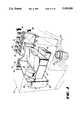
- FIG. 1is a partial perspective view of a post-mix beverage dispenser showing a beverage dispensing valve system according to one embodiment of the present invention
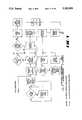
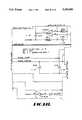
- FIG. 2is a partly diagrammatic, partly schematic diagram of the present invention
- FIG. 3is a perspective view of the flow control adjusting mechanism of this invention.
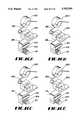
- FIG. 4is an enlarged perspective view of the movable carriage of the flow control adjusting mechanism, with FIGS. 4A, 4B and 4C showing different positions of the movable elements thereof as the solenoid is energized;
- FIG. 5is an enlarged rear view of the movable carriage of FIG. 4;
- FIG. 6is an end view of the flow control adjusting mechanism of FIGS. 3-5;
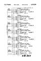
- FIGS. 7A, 7B, and 8-10are flow diagrams of the software
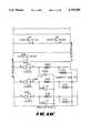
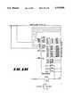
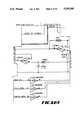
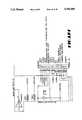
- FIGS. 11A-11N and 12A-12Eare electrical schematics of the electronic control system
- FIG. 13is a front view of a flow control adjusting mechanism according to a preferred embodiment of the present invention.
- FIG. 14is a top view of the mechanism of FIG. 13;
- FIG. 15is an end view of the mechanism of FIG. 13.
- FIGS. 16A-16Dare partial isometric views of the mechanism of FIG. 13 showing the operation thereof.
- FIGS. 1 and 2show a post-mix beverage dispenser 10 according to the present invention having an automatic ratio control system 12 for controlling the ratio of syrup to water in the beverage dispensed therefrom.
- the dispenser 10includes a dispensing valve 14 including a nozzle 16 and spout 18 for dispensing a beverage into a cup 20 positioned on a cup rest 22.
- the valve 14 and nozzle 16are preferably a multiflavor valve and nozzle and the dispenser 10 includes a plurality of syrup lines (one of which is shown at 24) and a soda (carbonated water) line 26.
- syrup linesone of which is shown at 24
- soda (carbonated water) line 26There is an inlet water line to the dispenser and both a soda line and a plain water line to the valve 14.
- Various known features of a dispensersuch as the carbonator and refrigeration system, are not described herein in detail.
- valve 14is an eight flavor valve and thus ten liquid conduits or lines are used, including eight syrup lines, one soda line and one plain water line.
- the automatic ratio control system 12includes the valve 14 and the electronic system 28.
- the valve 14includes eight syrup conduits (one of which 24 is shown), a soda conduit 26, a plain water conduit, a solenoid controlled on-off valve 30 in each conduit, a flow meter 32 in each conduit, a temperature sensor 34 in at least each syrup conduit, an adjustable flow control 36 in each conduit, and a mechanical flow control adjuster 38.
- the automatic ratio control system of this inventionincludes means for measuring the flow rate through each conduit (the flow meters 32 and temperature sensors 34), means for automatically comparing the measured flow rates with preferred ranges of flow rates (the electronic system 28), and means for automatically adjusting the flow controls at appropriate times.
- the flow meters 32can be of any type such as paddle wheel flow meters with flow sensors 35 for sensing rotation of the paddle wheels.
- the automatic flow control adjuster 38includes a flow control sprocket wheel 40 connected through a shaft 41 to each of the flow controls 36 and a movable actuator 42 for controllably rotating a selected one of the sprocket wheels 40.
- the sprocket wheelsare preferably arranged in a linear array and may or may not be equally spaced apart.
- the movable actuator 42includes a single drive sprocket 44, positioning means 46 for moving the drive sprocket into mating contact with any selected one of the flow control sprockets, and drive means 48 for turning the drive sprocket and in turn the selected flow control sprocket, a desired amount.
- the movable actuator 42will now be described in detail with reference to FIGS. 1-6.
- the actuator 42includes a stationary support 50 and a movable carriage 52 mounted for sliding movement thereon and carrying the single drive sprocket 44.
- the drive sprocket 44is moved out of mating engagement with a flow control sprocket wheel 40 when the carriage is moved by the positioning means and when the carriage movement is completed, the drive sprocket 44 is then moved into mating engagement with the selected flow control sprocket at which time the drive means 48 can turn the selected flow control sprocket wheel the desired amount.
- the stationary support 50includes the linear array of flow control sprocket wheels 40, a stepper motor 56, a drive chain 58, a chain movement sensor 60 including a toothed wheel 61 and a photosensor 62 to read movement of the wheel and therefore of the chain, a locking rail 64 with a plurality of locking pin detents 66 to lock the carriage 52 in place in any one of a number of selected positions, a position rail 68 with a plurality of position holes 70 for locating a selected position, a plurality of carriage guide rods 72, and a home position photodetector 74.
- the movable carriage 52includes a carriage body 76, a plurality of guide blocks 78 slidably mounting the carriage on the guide rods 72, the drive sprocket 44 rotatably mounted on a drive sprocket axle 80 which in turn is connected to a vertically movable slide 82 having an upper carriage travel position and a lower flow control adjusting position, a solenoid 84 which when energized moves the slide up to its carriage travel positions against the action of a bell crank return spring 86, a position seeking photodetector 88 positioned to sense said position holes 70 in said position rail, a home position sensor tab 90, a locking pin 92 mounted on a locking pin slide 94, a bell crank 96 pivotably movable about a pivot shaft 98 and having a locking pin slide cam 100 and a cam slot 102 for the drive sprocket slide 82.
- a drive belt locking lug 104is mounted above the drive sprocket to hold the drive chain thereto when the solenoid 84 is energized so the carriage 52 will move with the drive chain 58.
- a pair of idler rollers 106guides the chain onto the drive sprocket.
- a pair of springs 108bias the locking pin slide 94 downwardly.
- the carriageis preferably positioned at its home position with the drive sprocket 44 in mating engagement with the left most flow control sprocket wheel (as viewed in FIG. 3).
- the solenoid 84is energized causing the solenoid armature 110 to pull up rotating the bell crank 96 and first raising the slide 94 to move the locking pin 92 out of the detent 66 and then raising the slide 82 to move the drive sprocket 44 away from a sprocket wheel and holding the drive chain 58 to the drive sprocket.
- the stepper motor 56is then energized to move the drive chain and thus the carriage 52 until the carriage reaches the desired location as sensed by the position seeking photodetector 88.
- the solenoid 84is then de-energized to lock the carriage in place and to move the drive sprocket 44 into mating engagement with the flow control sprocket wheel 40 of the selected flow control 36 to be adjusted.
- the further movement of the drive chain 58 as controlled by the electronic systemrotates the flow control sprocket wheel the amount determined to be necessary to adjust the flow controlled thereby.
- the turning of the flow control sprocket wheeladjusts the flow control in the same manner as done manually in the prior art by a screwdriver, and thus such need not be described here.
- the amount of rotationis determined by the following data: (1) 1 full rotation of the flow control equals "X” oz/sec. flow rate change, (2) 1 full rotation equals “Y” stepper motor steps, and (3) present flow rate minus desired flow rate equals "Z" oz/sec. Then the appropriate number of steps are relayed to the stepper motor.
- the toothed wheel 61detects a flow control that is full in or full out to send an error message.
- FIGS. 4A, 4B and 4Cshow the positions of the various elements as the solenoid 84 is energized and begins to turn the bell crank 96.
- FIG. 4Ashows the various positions of the elements when the solenoid is not energized and
- FIG. 4Cshows the various positions of the elements after they have completed their movement.
- FIG. 4Bshows the positions of the various elements after the bell crank has moved about half way through its rotation. It is noted that the locking pin 92 is completely disengaged from the locking pin detents in the rail 64 before the drive sprocket moves up and holds the drive belt against the lug 104.
- the electronic control system of this inventionwill be evident to anyone skilled in the art by reference to FIGS. 7-12 which show the software and the electronic schematics. However, for the benefit of those not skilled in the art, the following additional explanation may be of benefit.
- the VQMvalve quality monitor
- the VQMthen sets a byte to request an initialization of the beverage dispenser system.
- the initialization processconsists of dispensing a series of 2 second draws for every syrup, each draw followed by an adjustment to the flow control if necessary (an adjustment is made if the flow rate error is outside, for example, ( ⁇ 4% error). This is done automatically by the VQM software with no interaction from the store personnel. When all of the circuits have been adjusted to within the specified error, the store personnel is notified and the VQM enters its normal operation mode.
- the VQMthen remains idle until signaled by the dispenser control board that a beverage is being dispensed.
- the information passed to the VQMincludes the syrup line and water or soda line currently in use.
- the VQMthen goes to the respective flowmeters and monitors pulses. This data, the period between pulses paired with syrup viscosity data is then interpreted into ounces of fluid dispensed. A timer is running throughout the data collection period, so that at the end of the dispense the total ounces is divided by the total ounces to calculate the fluid flow rate. This is done for the syrup and the water individually.
- this flow rateis compared to the desired flow rate and a flow rate error is then stored into a queue.
- the average error of the flowrateis calculated. If this error is above ⁇ 1% then a calculation is done to see what the adjustment to the flow control should be. Otherwise, the 101st dispense of this fluid is entered into the queue, the very first dispense is deleted and the average error of the last 100 drinks is calculated. This continues until an error of greater than ⁇ 1% is calculated on the last 100 drinks dispensed through any of the beverage lines. ##EQU1##
- the VQMthen sends motor steps in order to move the carriage to the appropriate flow control, it's position determined by the position sensor getting pulses every time it passes a flow control position. For example, if the carriage was to go to flow control 5, it would continue to send steps to the motor until it receives 5 pulses from the position sensor. Then the motor pulses stop and the solenoid on the carriage is de-energized.
- the VQMthen sends the specified number of step pulses in the specified direction (a positive number from the equation identifies a clockwise turn, a negative number a counter-clockwise turn) to the stepper motor. When the adjustment is finished the adjuster returns to the home position until another flow control has an adjustment required.
- the queue used to determine the flow control error trendis then emptied and another adjustment cannot occur on this particular flow control until at least 100 drinks of that flavor have been dispensed, in the presently preferred embodiment. Clearly other numbers can be used.
- a sensorIn the flow control has bottomed out in either direction and an adjustment is attempted to go further in that particular direction, a sensor has been added to alert an error condition.
- This sensorconsists of the photoelectric eye 62 that is placed on either side of a slotted wheel 61 that is attached to one of the chain sprockets.
- the pulses from the sensormust keep coming to the processor at a steady rate or else it is determined that the chain is not moving, therefore the sprocket attached to the flow control is not moving, and the flow control must be bottomed out.
- This erroris relayed to the store personnel as a possible hydraulic limit (in that the adjustment was to increase flow and the system pressures were not high enough to permit such a flow rate) or another error.
- the VQM systemis also monitoring the standard deviation of each flow control's queue of errors. It is known that the flow control has a deviation of about 3%. If the deviation is more than 5%, a warning is given to store personnel that the flow control in that certain circuit is possibly bad and needs to be replaced.
- Communication between the VQM and a beverage dispensing systemcan be done via an RS422 full duplex line.
- the host or master for the communicationis the beverage dispensing system, the slave being the VQM.
- the messages sentinclude the settings data at power up or as requested by a bit set in the VQM status. This status is requested by the host system and is communicated at least every second. Error and warning messages may be sent to the dispensing system through this communication line.
- the electronicsconsists of a circuit board with an Intel 80C196 microprocessor that monitors the flowmeters 32 and the drink switches (or receives status information from an operator panel) and controls the adjuster mechanism.
- Port 0Temperature inputs from the selected flavor and water as a drink is being poured, the in-position and home photo sensor signal from the adjuster mechanism, and the interrupt signal from the communication.
- Port 1Port 1 is not used.
- Port 2Receives and transmits serial data
- Port 3 and 4Address data busses for the 27512 64K EPROM and the 81C78A-45 8K RAM access;
- High Speed InputReceives the selected flavor and water flowmeter pulses, the rotation detector for the adjuster drive chain, and the scan feature.
- High Speed OutputDelivers the stepper motor pulses.
- Serial datais transmitted to a 74HC594 which generates a four bit flavor select code, three bits sent to an ADG507 multiplexer to select the flavor flowmeter to be connected to the input, one bit sent to an ADG212 multiplexer to select between water and soda flowmeters.
- Other serial data sent to this ICincludes enables for the drivers for the adjuster solenoid.
- FIGS. 13-16show a preferred embodiment of the present invention
- FIGS. 13-16show a flow control adjuster 200 that can be used in the dispenser 10 in place of the flow control adjuster 38 described above.
- the adjuster 200includes the flow control sprocket wheel 40 connected through the shaft 41 to each of the flow controls 36, and also includes an actuator 202 for controllably rotating a selected one of the sprocket wheels 40.
- the actuator 202includes a plurality of linear gear racks 204, one for each sprocket wheel, positioning means 206 for moving a selected one of the gear racks 204 into mating contact with its respective flow control sprocket, and drive means 208 for moving the selected gear rack and in turn the flow control sprocket, a desired amount.
- the gear racks 204are mounted in circumferentially and longitudinally different locations along a multi-rack adjusting shaft 210 mounted for rotation in a bracket 212.
- the shaft 210is rotated the desired amount to position a selected gear rack in contact with a selected flow control sprocket by a selector means 14 including a solenoid 216, a ratchet arm 218, and a shaft positioning gear 219.
- a selector means 14including a solenoid 216, a ratchet arm 218, and a shaft positioning gear 219.
- Each actuation of the solenoid 216turns the shaft 210 one position.
- the drive means 208includes a motor 220 and a drive chain 222 connected to an eccentric mechanism 223, which includes sprockets 225 for turning two shafts 224 and 226. Each shaft is connected in turn to an eccentric shaft 228 and 230 mounted for rotation in eccentric blocks 232 and 234. The blocks are attached to the bracket 212 that holds the shaft 210, to cause eccentric and reciprocating movement thereof such that the selected gear rack moves in an eccentric path.
- the motor 220turns in one direction
- the selected gear rackmoves in one direction (such as to the left in FIGS.
- the adjuster 200remains at the home position until an adjustment is needed.
- Homeis recognized by the use of a photosensor 240 that reflects off a flat section 242 of the multi-rack adjusting shaft 210.
- Home positionis also the position required for adjusting the leftmost flow control. When an adjustment is needed on one of the other flow controls, the following occurs.
- the solenoid 216actuates "x" times, causing the multi-rack adjusting shaft 210 to rotate such that the piece of gear rack for flow control "x+1" is in the downmost position.
- the solenoid actuationcauses the ratchet arm 218 to grab the positioning gear 219 and pull the shaft 210 around.
- the gear 219has a detent 244 to lock the shaft 210 in position.
- Various detentscan be used, however, the preferred one is a ball held in a tube and spring biased against the gear 219.
- the shaft 210only rotates in one direction (counterclockwise as viewed in FIG. 15).
- There is a position sensor 246 on the other end of the shaft 210to ensure that each time the solenoid 216 is actuated, the shaft 210 actually moves.
- the position sensor 246includes an encoder 248 that alternates dark and light to be sensed each time the solenoid 216 is actuated (i.e. position 2 light, position 3 dark, position 4 light,
- the motor 220(which can be a stepper motor or a simple bi-directional dc motor) is powered and the drive chain 222 moves the eccentric mechanism 223 via drive sprockets 225 that causes the multi-rack adjusting shaft 210 and all of the associated bracket and hardware to move in an eccentric motion.
- the bottom part of this motioncauses the selected gear rack 204 to come into mating contact with the selected flow control gear sprocket 40 and moves the sprocket one tooth either clockwise or counterclockwise, depending on the motor direction.
- An eccentric rotation sensor 250consists of an encoder 252 with a single slot that permits a light sensor 254 to detect a single point of the complete rotation (in the current design this senses the uppermost position of the eccentric rotation). The motor 220 would remain energized until the rotation sensor 250 "sees" the number of rotations corresponding to the magnitude of adjustment that is desired.
- the solenoid 216energizes until the racked shaft 210 is back at the home position.
- the adjuster 200attaches to the valve 142 at only two locations, by means of two attachment screws 256 with relief springs 258.
- the purpose of the springs 258is to allow play in the eccentric motion in case the rack piece does not engage cleanly with the gear sprocket of the flow control. In the case when the two meet tooth to tooth, the spring would allow the rack to ride up until the eccentric path brings the rack around enough to drop down and engage.
- Each flow controlis equipped with a gear sprocket as with the previously described design.
- a sprocket aligning rackis used to keep the sprockets in a single line.
- This embodimentallows much more access to the valve components for maintenance. Tolerances are less important to the operation of this adjuster mechanism 200.
- Another feature of this embodimentis the exacting adjustment procedure. Every time the eccentric goes through one complete motion, the flow control is moved exactly one tooth. Further, this embodiment has fewer pieces, is easier to assemble and will be less expensive than the previously described embodiment.
Landscapes
- Physics & Mathematics (AREA)
- Chemical & Material Sciences (AREA)
- Analytical Chemistry (AREA)
- Fluid Mechanics (AREA)
- Devices For Dispensing Beverages (AREA)
Abstract
Description
Claims (15)
Priority Applications (1)
| Application Number | Priority Date | Filing Date | Title |
|---|---|---|---|
| US07/739,742US5192000A (en) | 1990-05-14 | 1991-08-02 | Beverage dispenser with automatic ratio control |
Applications Claiming Priority (2)
| Application Number | Priority Date | Filing Date | Title |
|---|---|---|---|
| US52262790A | 1990-05-14 | 1990-05-14 | |
| US07/739,742US5192000A (en) | 1990-05-14 | 1991-08-02 | Beverage dispenser with automatic ratio control |
Related Parent Applications (1)
| Application Number | Title | Priority Date | Filing Date |
|---|---|---|---|
| US52262790AContinuation-In-Part | 1990-05-14 | 1990-05-14 |
Publications (1)
| Publication Number | Publication Date |
|---|---|
| US5192000Atrue US5192000A (en) | 1993-03-09 |
Family
ID=27060872
Family Applications (1)
| Application Number | Title | Priority Date | Filing Date |
|---|---|---|---|
| US07/739,742Expired - Fee RelatedUS5192000A (en) | 1990-05-14 | 1991-08-02 | Beverage dispenser with automatic ratio control |
Country Status (1)
| Country | Link |
|---|---|
| US (1) | US5192000A (en) |
Cited By (40)
| Publication number | Priority date | Publication date | Assignee | Title |
|---|---|---|---|---|
| US5782109A (en)* | 1996-05-06 | 1998-07-21 | Ecolab Inc. | Dispenser |
| US5816448A (en)* | 1993-12-09 | 1998-10-06 | Kobold; Klaus | Dosing device and system for accurate dosing of fluids |
| US5857589A (en)* | 1996-11-20 | 1999-01-12 | Fluid Research Corporation | Method and apparatus for accurately dispensing liquids and solids |
| US5975352A (en)* | 1997-08-28 | 1999-11-02 | Ecolab Inc. | Dispenser |
| US5992686A (en)* | 1998-02-27 | 1999-11-30 | Fluid Research Corporation | Method and apparatus for dispensing liquids and solids |
| US6237810B1 (en) | 2000-03-29 | 2001-05-29 | The Coca-Cola Company | Modular beverage dispenser |
| US6325244B2 (en)* | 1999-07-15 | 2001-12-04 | Grand Soft Equipment Co. | Method for dispensing a desired portion of frozen product |
| US6600968B2 (en)* | 1999-05-20 | 2003-07-29 | Lancer Partnership, Ltd. | Beverage dispenser including an improved electronic control system |
| US20040144423A1 (en)* | 2003-01-28 | 2004-07-29 | Everett William F. | Method and apparatus for flow control |
| US6807460B2 (en) | 2001-12-28 | 2004-10-19 | Pepsico, Inc. | Beverage quality and communications control for a beverage forming and dispensing system |
| US20070068393A1 (en)* | 2005-04-11 | 2007-03-29 | Coffee Equipment Company | Machine for brewing a beverage such as coffee and related method |
| US20080054837A1 (en)* | 2006-03-06 | 2008-03-06 | Beavis Russell H | System and method for generating a drive signal |
| US20080073610A1 (en)* | 1997-08-22 | 2008-03-27 | Manning Casey P | Stopcock valve |
| US20090095165A1 (en)* | 2005-04-11 | 2009-04-16 | Coffee Equipment Company | Machine for brewing a beverage such as coffee and related method |
| US20090159612A1 (en)* | 2007-09-06 | 2009-06-25 | Deka Research & Development Corp. | Product dispensing system |
| US20090277516A1 (en) | 2006-03-06 | 2009-11-12 | Felix Winkler | Product Dispensing System |
| US20100005903A1 (en)* | 2007-09-06 | 2010-01-14 | Deka Products Limited Partnership | Product Dispensing System |
| EP1513752A4 (en)* | 2002-05-17 | 2010-11-10 | Pepsico Inc | Beverage forming and dispensing system |
| WO2011137502A1 (en)* | 2010-05-04 | 2011-11-10 | Antonio Benoaldo Amorim Dos Santos Silva | Circuit and method for controlling dispensing appliances, and magnetic sensor for manometers |
| US20150046877A1 (en)* | 2013-08-07 | 2015-02-12 | The Coca-Cola Company | Dynamically Adjusting Ratios of Beverages in a Mixed Beverage |
| US20160222332A1 (en)* | 2015-01-30 | 2016-08-04 | Anheuser-Busch Inbev S.A. | Methods, appliances, and systems for preparing a beverage from a base liquid and an ingredient |
| US9415992B2 (en) | 2006-03-06 | 2016-08-16 | The Coca-Cola Company | Dispenser for beverages having a rotary micro-ingredient combination chamber |
| US20170243430A1 (en)* | 2016-02-23 | 2017-08-24 | Cornelius, Inc. | Beverage dispensing validation method and system |
| US20180153193A1 (en)* | 2015-05-11 | 2018-06-07 | Next Proteins, Inc. | Method and system for making carbonated protein beverage compositions |
| US10167863B1 (en) | 2012-03-28 | 2019-01-01 | Pumptec, Inc. | Proportioning pump, control systems and applicator apparatus |
| US10280060B2 (en) | 2006-03-06 | 2019-05-07 | The Coca-Cola Company | Dispenser for beverages having an ingredient mixing module |
| US10760557B1 (en) | 2016-05-06 | 2020-09-01 | Pumptec, Inc. | High efficiency, high pressure pump suitable for remote installations and solar power sources |
| US10823160B1 (en) | 2017-01-12 | 2020-11-03 | Pumptec Inc. | Compact pump with reduced vibration and reduced thermal degradation |
| US11135345B2 (en) | 2017-05-10 | 2021-10-05 | Fresenius Medical Care Holdings, Inc. | On demand dialysate mixing using concentrates |
| US11208314B2 (en) | 2015-01-30 | 2021-12-28 | Anheuser-Busch Inbev S.A. | Pressurized beverage concentrates and appliances and methods for producing beverages therefrom |
| CN113856539A (en)* | 2021-10-29 | 2021-12-31 | 东莞市新展新自动化科技有限公司 | Water paint processing is with deciding than compounding device |
| US11427462B2 (en) | 2007-09-06 | 2022-08-30 | Deka Products Limited Partnership | Product dispensing system |
| US11504458B2 (en) | 2018-10-17 | 2022-11-22 | Fresenius Medical Care Holdings, Inc. | Ultrasonic authentication for dialysis |
| US11634311B2 (en) | 2007-09-06 | 2023-04-25 | Deka Products Limited Partnership | Product dispensing system |
| US11655806B2 (en) | 2007-09-06 | 2023-05-23 | Deka Products Limited Partnership | Product dispensing system |
| US11661329B2 (en) | 2006-03-06 | 2023-05-30 | Deka Products Limited Partnership | System and method for generating a drive signal |
| US11702331B2 (en) | 2019-05-03 | 2023-07-18 | Marmon Foodservice Technologies, Inc. | Beverage dispensing machines with dispensing valves |
| US11906988B2 (en) | 2006-03-06 | 2024-02-20 | Deka Products Limited Partnership | Product dispensing system |
| EP4106586A4 (en)* | 2020-02-21 | 2024-03-27 | Bartrack, Inc. | Monitoring equilibrium and dispensement of a fluid dispensement system to improve quality and efficiency |
| US12135019B2 (en) | 2007-09-06 | 2024-11-05 | Deka Products Limited Partnership | Product dispensing system |
Citations (28)
| Publication number | Priority date | Publication date | Assignee | Title |
|---|---|---|---|---|
| US3195780A (en)* | 1961-01-23 | 1965-07-20 | Veeder Root Inc | Apparatus for dispensing preselected mixtures of liquids |
| US3272217A (en)* | 1962-03-16 | 1966-09-13 | Sun Oil Co | Systems for proportioning fluids |
| US3439552A (en)* | 1966-03-15 | 1969-04-22 | Rolls Royce | Selective drive device |
| US3474815A (en)* | 1965-12-17 | 1969-10-28 | Crown Cork & Seal Co | Fluid proportioning and blending system |
| US3604419A (en)* | 1968-09-19 | 1971-09-14 | Technion Res & Dev Foundation | Apparatus for urinary bladder treatment |
| US3650434A (en)* | 1970-04-06 | 1972-03-21 | Republic Corp | Liquid proportioning device |
| US3768510A (en)* | 1971-06-23 | 1973-10-30 | Dart Ind Inc | Method and apparatus for flow rate calibration |
| US3783899A (en)* | 1972-02-24 | 1974-01-08 | Rockwell International Corp | Valve operator |
| US3838797A (en)* | 1971-01-11 | 1974-10-01 | Dresser Ind | Prepositioning device for a blend control valve |
| US3948419A (en)* | 1974-08-01 | 1976-04-06 | Concession Service Corporation | Beverage fluid flow controller |
| US3999686A (en)* | 1973-01-18 | 1976-12-28 | Mitsubishi Rayon Co., Ltd. | Apparatus for continuously mixing and monitoring a syrup mixture |
| US4020977A (en)* | 1974-06-24 | 1977-05-03 | Hechler Iv Valentine | Continuous flow ratio monitor |
| US4202387A (en)* | 1977-08-10 | 1980-05-13 | Upton Douglas J | Fluid dispensing control system |
| US4234007A (en)* | 1978-08-14 | 1980-11-18 | Scientific Applications Incorporated | Automatic liquid flow control device |
| US4246969A (en)* | 1979-02-07 | 1981-01-27 | John McLoughlin | Chemical injection system for fire fighting |
| US4281777A (en)* | 1978-04-06 | 1981-08-04 | Akens Robert L | Dual liquid proportioning apparatus |
| US4487333A (en)* | 1982-02-26 | 1984-12-11 | Signet Scientific Co. | Fluid dispensing system |
| US4559831A (en)* | 1983-09-26 | 1985-12-24 | Siemens Aktiengesellschaft | Method and device for flow measurement of small liquid volumes |
| US4708266A (en)* | 1986-03-21 | 1987-11-24 | The Coca-Cola Company | Concentrate dispensing system for a post-mix beverage dispenser |
| US4815632A (en)* | 1985-05-04 | 1989-03-28 | Jencons (Scientific) Limited | Liquid dosing device with digital display |
| US4821925A (en)* | 1987-05-14 | 1989-04-18 | The Coca-Cola Company | Narrow, multiflavor beverage dispenser valve assembly and tower |
| US4876653A (en)* | 1987-07-15 | 1989-10-24 | Mcspadden John S | Programmable multiple blender |
| US4884720A (en)* | 1987-06-05 | 1989-12-05 | The Coca-Cola Company | Post-mix beverage dispenser valve with continuous solenoid modulation |
| US4967808A (en)* | 1988-03-29 | 1990-11-06 | The Coca-Cola Company | Automatic beverage dispensing system |
| US4979639A (en)* | 1989-05-23 | 1990-12-25 | The Coca-Cola Company | Beverage dispenser control valve and ratio control method therefor |
| US5012955A (en)* | 1989-10-30 | 1991-05-07 | Abc/Sebrn Techcorp. | Syrup dispensing system |
| US5033644A (en)* | 1989-03-31 | 1991-07-23 | Tentler Michael L | Precision dispensing of varying viscosity fluids in a prescribed mix ratio |
| US5038971A (en)* | 1989-09-29 | 1991-08-13 | Tokheim Corporation | Variable blending dispenser |
- 1991
- 1991-08-02USUS07/739,742patent/US5192000A/ennot_activeExpired - Fee Related
Patent Citations (28)
| Publication number | Priority date | Publication date | Assignee | Title |
|---|---|---|---|---|
| US3195780A (en)* | 1961-01-23 | 1965-07-20 | Veeder Root Inc | Apparatus for dispensing preselected mixtures of liquids |
| US3272217A (en)* | 1962-03-16 | 1966-09-13 | Sun Oil Co | Systems for proportioning fluids |
| US3474815A (en)* | 1965-12-17 | 1969-10-28 | Crown Cork & Seal Co | Fluid proportioning and blending system |
| US3439552A (en)* | 1966-03-15 | 1969-04-22 | Rolls Royce | Selective drive device |
| US3604419A (en)* | 1968-09-19 | 1971-09-14 | Technion Res & Dev Foundation | Apparatus for urinary bladder treatment |
| US3650434A (en)* | 1970-04-06 | 1972-03-21 | Republic Corp | Liquid proportioning device |
| US3838797A (en)* | 1971-01-11 | 1974-10-01 | Dresser Ind | Prepositioning device for a blend control valve |
| US3768510A (en)* | 1971-06-23 | 1973-10-30 | Dart Ind Inc | Method and apparatus for flow rate calibration |
| US3783899A (en)* | 1972-02-24 | 1974-01-08 | Rockwell International Corp | Valve operator |
| US3999686A (en)* | 1973-01-18 | 1976-12-28 | Mitsubishi Rayon Co., Ltd. | Apparatus for continuously mixing and monitoring a syrup mixture |
| US4020977A (en)* | 1974-06-24 | 1977-05-03 | Hechler Iv Valentine | Continuous flow ratio monitor |
| US3948419A (en)* | 1974-08-01 | 1976-04-06 | Concession Service Corporation | Beverage fluid flow controller |
| US4202387A (en)* | 1977-08-10 | 1980-05-13 | Upton Douglas J | Fluid dispensing control system |
| US4281777A (en)* | 1978-04-06 | 1981-08-04 | Akens Robert L | Dual liquid proportioning apparatus |
| US4234007A (en)* | 1978-08-14 | 1980-11-18 | Scientific Applications Incorporated | Automatic liquid flow control device |
| US4246969A (en)* | 1979-02-07 | 1981-01-27 | John McLoughlin | Chemical injection system for fire fighting |
| US4487333A (en)* | 1982-02-26 | 1984-12-11 | Signet Scientific Co. | Fluid dispensing system |
| US4559831A (en)* | 1983-09-26 | 1985-12-24 | Siemens Aktiengesellschaft | Method and device for flow measurement of small liquid volumes |
| US4815632A (en)* | 1985-05-04 | 1989-03-28 | Jencons (Scientific) Limited | Liquid dosing device with digital display |
| US4708266A (en)* | 1986-03-21 | 1987-11-24 | The Coca-Cola Company | Concentrate dispensing system for a post-mix beverage dispenser |
| US4821925A (en)* | 1987-05-14 | 1989-04-18 | The Coca-Cola Company | Narrow, multiflavor beverage dispenser valve assembly and tower |
| US4884720A (en)* | 1987-06-05 | 1989-12-05 | The Coca-Cola Company | Post-mix beverage dispenser valve with continuous solenoid modulation |
| US4876653A (en)* | 1987-07-15 | 1989-10-24 | Mcspadden John S | Programmable multiple blender |
| US4967808A (en)* | 1988-03-29 | 1990-11-06 | The Coca-Cola Company | Automatic beverage dispensing system |
| US5033644A (en)* | 1989-03-31 | 1991-07-23 | Tentler Michael L | Precision dispensing of varying viscosity fluids in a prescribed mix ratio |
| US4979639A (en)* | 1989-05-23 | 1990-12-25 | The Coca-Cola Company | Beverage dispenser control valve and ratio control method therefor |
| US5038971A (en)* | 1989-09-29 | 1991-08-13 | Tokheim Corporation | Variable blending dispenser |
| US5012955A (en)* | 1989-10-30 | 1991-05-07 | Abc/Sebrn Techcorp. | Syrup dispensing system |
Cited By (75)
| Publication number | Priority date | Publication date | Assignee | Title |
|---|---|---|---|---|
| US5816448A (en)* | 1993-12-09 | 1998-10-06 | Kobold; Klaus | Dosing device and system for accurate dosing of fluids |
| US5873268A (en)* | 1996-05-06 | 1999-02-23 | Ecolab Inc. | Dispenser |
| US5782109A (en)* | 1996-05-06 | 1998-07-21 | Ecolab Inc. | Dispenser |
| US6286566B1 (en) | 1996-11-20 | 2001-09-11 | Fluid Research Corporation | Method and apparatus for accurately dispensing liquids and solids |
| US5857589A (en)* | 1996-11-20 | 1999-01-12 | Fluid Research Corporation | Method and apparatus for accurately dispensing liquids and solids |
| US6126039A (en)* | 1996-11-20 | 2000-10-03 | Fluid Research Corporation | Method and apparatus for accurately dispensing liquids and solids |
| US20080073610A1 (en)* | 1997-08-22 | 2008-03-27 | Manning Casey P | Stopcock valve |
| US5975352A (en)* | 1997-08-28 | 1999-11-02 | Ecolab Inc. | Dispenser |
| US6143257A (en)* | 1997-08-28 | 2000-11-07 | Ecolab Inc. | Dispenser |
| US6161723A (en)* | 1998-02-27 | 2000-12-19 | Fluid Research Corporation | Method and apparatus for dispensing liquids and solids |
| US6675988B2 (en) | 1998-02-27 | 2004-01-13 | Fluid Research Corporation | Apparatus for dispensing liquids and solids |
| US20040104244A1 (en)* | 1998-02-27 | 2004-06-03 | Cline David J. | Apparatus for dispensing liquids and solids |
| US5992686A (en)* | 1998-02-27 | 1999-11-30 | Fluid Research Corporation | Method and apparatus for dispensing liquids and solids |
| US6913166B2 (en) | 1998-02-27 | 2005-07-05 | Fluid Research | Apparatus for dispensing liquids and solids |
| US6600968B2 (en)* | 1999-05-20 | 2003-07-29 | Lancer Partnership, Ltd. | Beverage dispenser including an improved electronic control system |
| US6325244B2 (en)* | 1999-07-15 | 2001-12-04 | Grand Soft Equipment Co. | Method for dispensing a desired portion of frozen product |
| US6237810B1 (en) | 2000-03-29 | 2001-05-29 | The Coca-Cola Company | Modular beverage dispenser |
| US6807460B2 (en) | 2001-12-28 | 2004-10-19 | Pepsico, Inc. | Beverage quality and communications control for a beverage forming and dispensing system |
| EP1513752A4 (en)* | 2002-05-17 | 2010-11-10 | Pepsico Inc | Beverage forming and dispensing system |
| US7156115B2 (en)* | 2003-01-28 | 2007-01-02 | Lancer Partnership, Ltd | Method and apparatus for flow control |
| US20040144423A1 (en)* | 2003-01-28 | 2004-07-29 | Everett William F. | Method and apparatus for flow control |
| US20070068393A1 (en)* | 2005-04-11 | 2007-03-29 | Coffee Equipment Company | Machine for brewing a beverage such as coffee and related method |
| US20090095165A1 (en)* | 2005-04-11 | 2009-04-16 | Coffee Equipment Company | Machine for brewing a beverage such as coffee and related method |
| US8621982B2 (en) | 2005-04-11 | 2014-01-07 | Starbucks Corporation | Temperature-controlled beverage brewing |
| US8371211B2 (en) | 2005-04-11 | 2013-02-12 | Starbucks Corporation | Machine for brewing a beverage such as coffee and related method |
| US20110088560A1 (en)* | 2005-04-11 | 2011-04-21 | Starbucks Corporation | Machine for Brewing a Beverage Such as Coffee and Related Method |
| US20100024657A9 (en)* | 2005-04-11 | 2010-02-04 | Coffee Equipment Company | Machine for brewing a beverage such as coffee and related method |
| US7673555B2 (en) | 2005-04-11 | 2010-03-09 | Starbucks Corporation | Machine for brewing a beverage such as coffee and related method |
| US9402406B2 (en) | 2005-04-11 | 2016-08-02 | Starbucks Corporation | Beverage brewer with flavor base removal |
| US20100154645A1 (en)* | 2005-09-20 | 2010-06-24 | Starbucks Corporation | Method for brewing a beverage such as coffee and related method |
| US10667642B2 (en) | 2005-09-20 | 2020-06-02 | Starbucks Corporation | Machine for brewing a beverage such as coffee and related method |
| US8794127B2 (en) | 2005-09-20 | 2014-08-05 | Starbucks Corporation | Machine for brewing a beverage such as coffee and related method |
| US11906988B2 (en) | 2006-03-06 | 2024-02-20 | Deka Products Limited Partnership | Product dispensing system |
| US7905373B2 (en) | 2006-03-06 | 2011-03-15 | Deka Products Limited Partnership | System and method for generating a drive signal |
| US11429120B2 (en) | 2006-03-06 | 2022-08-30 | Deka Products Limited Partnership | Product dispensing system |
| US11661329B2 (en) | 2006-03-06 | 2023-05-30 | Deka Products Limited Partnership | System and method for generating a drive signal |
| US20100206400A2 (en)* | 2006-03-06 | 2010-08-19 | Felix Winkler | Product Dispensing System |
| US20090277516A1 (en) | 2006-03-06 | 2009-11-12 | Felix Winkler | Product Dispensing System |
| US11975960B2 (en) | 2006-03-06 | 2024-05-07 | Deka Products Limited Partnership | System and method for generating a drive signal |
| US10280060B2 (en) | 2006-03-06 | 2019-05-07 | The Coca-Cola Company | Dispenser for beverages having an ingredient mixing module |
| US20080054837A1 (en)* | 2006-03-06 | 2008-03-06 | Beavis Russell H | System and method for generating a drive signal |
| US9415992B2 (en) | 2006-03-06 | 2016-08-16 | The Coca-Cola Company | Dispenser for beverages having a rotary micro-ingredient combination chamber |
| US9146564B2 (en) | 2006-03-06 | 2015-09-29 | Deka Products Limited Partnership | Product dispensing system |
| US8087303B2 (en) | 2007-09-06 | 2012-01-03 | Deka Products Limited Partnership | Product dispensing system |
| US12135019B2 (en) | 2007-09-06 | 2024-11-05 | Deka Products Limited Partnership | Product dispensing system |
| US11655806B2 (en) | 2007-09-06 | 2023-05-23 | Deka Products Limited Partnership | Product dispensing system |
| US11634311B2 (en) | 2007-09-06 | 2023-04-25 | Deka Products Limited Partnership | Product dispensing system |
| US11738989B2 (en) | 2007-09-06 | 2023-08-29 | Deka Products Limited Partnership | Product dispensing system |
| US11427462B2 (en) | 2007-09-06 | 2022-08-30 | Deka Products Limited Partnership | Product dispensing system |
| US8783513B2 (en)* | 2007-09-06 | 2014-07-22 | Deka Products Limited Partnership | Product dispensing system |
| US11365107B2 (en) | 2007-09-06 | 2022-06-21 | Deka Products Limited Partnership | Product dispensing system |
| US20100005903A1 (en)* | 2007-09-06 | 2010-01-14 | Deka Products Limited Partnership | Product Dispensing System |
| US8322570B2 (en) | 2007-09-06 | 2012-12-04 | Deka Products Limited Partnership | Product dispensing system |
| US12338116B2 (en) | 2007-09-06 | 2025-06-24 | Deka Products Limited Partneship | Product dispensing system |
| US20110011888A2 (en)* | 2007-09-06 | 2011-01-20 | Russell Beavis | Product dispensing system |
| US20090159612A1 (en)* | 2007-09-06 | 2009-06-25 | Deka Research & Development Corp. | Product dispensing system |
| US12372987B2 (en) | 2009-05-07 | 2025-07-29 | Deka Products Limited Partnership | Product dispensing system |
| WO2011137502A1 (en)* | 2010-05-04 | 2011-11-10 | Antonio Benoaldo Amorim Dos Santos Silva | Circuit and method for controlling dispensing appliances, and magnetic sensor for manometers |
| US10167863B1 (en) | 2012-03-28 | 2019-01-01 | Pumptec, Inc. | Proportioning pump, control systems and applicator apparatus |
| US10384925B2 (en)* | 2013-08-07 | 2019-08-20 | The Coca-Cola Company | Dynamically adjusting ratios of beverages in a mixed beverage |
| US20150046877A1 (en)* | 2013-08-07 | 2015-02-12 | The Coca-Cola Company | Dynamically Adjusting Ratios of Beverages in a Mixed Beverage |
| US11208314B2 (en) | 2015-01-30 | 2021-12-28 | Anheuser-Busch Inbev S.A. | Pressurized beverage concentrates and appliances and methods for producing beverages therefrom |
| US20160222332A1 (en)* | 2015-01-30 | 2016-08-04 | Anheuser-Busch Inbev S.A. | Methods, appliances, and systems for preparing a beverage from a base liquid and an ingredient |
| US20180153193A1 (en)* | 2015-05-11 | 2018-06-07 | Next Proteins, Inc. | Method and system for making carbonated protein beverage compositions |
| US10515327B2 (en)* | 2016-02-23 | 2019-12-24 | Cornelius, Inc. | Beverage dispensing validation method and system |
| US20170243430A1 (en)* | 2016-02-23 | 2017-08-24 | Cornelius, Inc. | Beverage dispensing validation method and system |
| US10760557B1 (en) | 2016-05-06 | 2020-09-01 | Pumptec, Inc. | High efficiency, high pressure pump suitable for remote installations and solar power sources |
| US10823160B1 (en) | 2017-01-12 | 2020-11-03 | Pumptec Inc. | Compact pump with reduced vibration and reduced thermal degradation |
| US11752246B2 (en) | 2017-05-10 | 2023-09-12 | Fresenius Medical Care Holdings, Inc. | On demand dialysate mixing using concentrates |
| US11135345B2 (en) | 2017-05-10 | 2021-10-05 | Fresenius Medical Care Holdings, Inc. | On demand dialysate mixing using concentrates |
| US11504458B2 (en) | 2018-10-17 | 2022-11-22 | Fresenius Medical Care Holdings, Inc. | Ultrasonic authentication for dialysis |
| US11702331B2 (en) | 2019-05-03 | 2023-07-18 | Marmon Foodservice Technologies, Inc. | Beverage dispensing machines with dispensing valves |
| EP4106586A4 (en)* | 2020-02-21 | 2024-03-27 | Bartrack, Inc. | Monitoring equilibrium and dispensement of a fluid dispensement system to improve quality and efficiency |
| US12180056B2 (en) | 2020-02-21 | 2024-12-31 | Bartrack, Inc. | Monitoring equilibrium and dispensement of a fluid dispensement system to improve quality and efficiency |
| CN113856539A (en)* | 2021-10-29 | 2021-12-31 | 东莞市新展新自动化科技有限公司 | Water paint processing is with deciding than compounding device |
Similar Documents
| Publication | Publication Date | Title |
|---|---|---|
| US5192000A (en) | Beverage dispenser with automatic ratio control | |
| US4821921A (en) | Liquid dispensing apparatus | |
| US5022557A (en) | Computerized beverage dispensing system | |
| US4884720A (en) | Post-mix beverage dispenser valve with continuous solenoid modulation | |
| CA1333099C (en) | Proportional chemical feeding systems | |
| US5695092A (en) | Fluid flow measuring system | |
| EP2771579B1 (en) | Product dispensing system with pwm controlled solenoid pump | |
| US20100127015A1 (en) | Beverage proportioning | |
| KR20010101839A (en) | Beverage dispenser with modular volumetric valve system | |
| WO2001019718A1 (en) | Coaxial vapor flow indicator with pump speed control | |
| CA2016803A1 (en) | Automated drinkmaker system | |
| US5129434A (en) | Beverage dispensing valve with flow control lever arm | |
| WO2012175693A2 (en) | A liquid pour metering device | |
| GB2134089A (en) | Volumetric filling machine | |
| CN113195398B (en) | Reflux detection and mixing module with thermal mass flowmeter | |
| WO1991017950A2 (en) | Beverage dispenser with automatic ratio control | |
| US5677481A (en) | Viscosity maintenance | |
| EP1088784B1 (en) | Apparatus for making and dispensing slush-type beverages | |
| CN214618132U (en) | Water tap capable of quantitatively discharging water | |
| CN116173352B (en) | Automatic transfusion monitoring method and system based on weight monitoring | |
| GB2263687A (en) | Beverage dispensing apparatus | |
| JP3825610B2 (en) | Coffee beverage production equipment | |
| NZ208033A (en) | Method and apparatus for measuring quantity of milk obtained by milking machine | |
| CN209214546U (en) | A kind of copper bandlet thickness detection apparatus on calender | |
| WO1990015012A1 (en) | Liquid dispensing apparatus |
Legal Events
| Date | Code | Title | Description |
|---|---|---|---|
| AS | Assignment | Owner name:COCA-COLA COMPANY, THE, GEORGIA Free format text:ASSIGNMENT OF ASSIGNORS INTEREST.;ASSIGNORS:WANDRICK, LISA C.;HOOVER, GEORGE H.;WHIGHAM, ROGER C.;REEL/FRAME:005794/0751 Effective date:19910802 | |
| AS | Assignment | Owner name:WILLDEN INDUSTRIES, INC., GEORGIA Free format text:ASSIGNMENT OF ASSIGNORS INTEREST.;ASSIGNOR:BEARDEN, JOHN H.;REEL/FRAME:006220/0054 Effective date:19911010 Owner name:COCA-COLA COMPANY, THE, GEORGIA Free format text:ASSIGNMENT OF ASSIGNORS INTEREST.;ASSIGNOR:WILLDEN INDUSTRIES, INC., A GA CORP.;REEL/FRAME:006220/0059 Effective date:19911010 | |
| CC | Certificate of correction | ||
| FPAY | Fee payment | Year of fee payment:4 | |
| FEPP | Fee payment procedure | Free format text:PAYOR NUMBER ASSIGNED (ORIGINAL EVENT CODE: ASPN); ENTITY STATUS OF PATENT OWNER: LARGE ENTITY | |
| FPAY | Fee payment | Year of fee payment:8 | |
| REMI | Maintenance fee reminder mailed | ||
| LAPS | Lapse for failure to pay maintenance fees | ||
| STCH | Information on status: patent discontinuation | Free format text:PATENT EXPIRED DUE TO NONPAYMENT OF MAINTENANCE FEES UNDER 37 CFR 1.362 | |
| FP | Lapsed due to failure to pay maintenance fee | Effective date:20050309 |