US5191855A - Battery missing indicator - Google Patents
Battery missing indicatorDownload PDFInfo
- Publication number
- US5191855A US5191855AUS07/485,221US48522190AUS5191855AUS 5191855 AUS5191855 AUS 5191855AUS 48522190 AUS48522190 AUS 48522190AUS 5191855 AUS5191855 AUS 5191855A
- Authority
- US
- United States
- Prior art keywords
- battery
- cover
- base
- detector
- present
- Prior art date
- Legal status (The legal status is an assumption and is not a legal conclusion. Google has not performed a legal analysis and makes no representation as to the accuracy of the status listed.)
- Expired - Lifetime
Links
- 230000000903blocking effectEffects0.000claimsabstractdescription22
- 230000002401inhibitory effectEffects0.000claims2
- 239000000779smokeSubstances0.000description9
- 230000000007visual effectEffects0.000description3
- 238000001514detection methodMethods0.000description2
- 238000012986modificationMethods0.000description2
- 230000004048modificationEffects0.000description2
- 230000000994depressogenic effectEffects0.000description1
- 238000011161developmentMethods0.000description1
- 230000018109developmental processEffects0.000description1
- 230000005484gravityEffects0.000description1
Images


Classifications
- G—PHYSICS
- G08—SIGNALLING
- G08B—SIGNALLING OR CALLING SYSTEMS; ORDER TELEGRAPHS; ALARM SYSTEMS
- G08B29/00—Checking or monitoring of signalling or alarm systems; Prevention or correction of operating errors, e.g. preventing unauthorised operation
- G08B29/18—Prevention or correction of operating errors
- G08B29/181—Prevention or correction of operating errors due to failing power supply
- G—PHYSICS
- G08—SIGNALLING
- G08B—SIGNALLING OR CALLING SYSTEMS; ORDER TELEGRAPHS; ALARM SYSTEMS
- G08B17/00—Fire alarms; Alarms responsive to explosion
- G—PHYSICS
- G08—SIGNALLING
- G08B—SIGNALLING OR CALLING SYSTEMS; ORDER TELEGRAPHS; ALARM SYSTEMS
- G08B17/00—Fire alarms; Alarms responsive to explosion
- G08B17/10—Actuation by presence of smoke or gases, e.g. automatic alarm devices for analysing flowing fluid materials by the use of optical means
- G08B17/11—Actuation by presence of smoke or gases, e.g. automatic alarm devices for analysing flowing fluid materials by the use of optical means using an ionisation chamber for detecting smoke or gas
- G08B17/113—Constructional details
Definitions
- the inventionpertains to structures for visually indicating that a battery is missing from a battery powered electrical unit. More particularly, the invention pertains to visual flags usable with battery powered smoke detectors to indicate the absence of a battery.
- Smoke detectorsare very commonly found today in buildings of all types. Some of these smoke detectors are AC powered. Others are battery powered. Some include a combination of AC power and battery backup power.
- Battery powered detectorswhile very convenient and easy to install, have suffered from the drawback that a user of the building might not realize the unit needed a battery. As such, because there was no indicia of a missing battery, this condition could persist for a substantial period of time to and including the time when a fire strikes the building. At that point in time, the detector would of course not function and not give out the warning it was intended to provide.
- the drawercan be freely opened and closed.
- the detectorcan receive electrical energy from the battery.
- the drawerWhen the battery is removed from the drawer, the drawer is locked open and cannot be closed. This provides a visual indication of the missing battery.
- drawer approachdoes provide an acceptable solution to the battery indicator problem from a consumer's point of view, from a manufacturer's point of view, it tends to be rather expensive and complicated.
- An alternate prior art battery missing indicatorhas been incorporated into a smoke detector which is intended to be removably affixed to a surface mounted bracket.
- the bracketmight be mounted on the ceiling or the wall of a room.
- a movable obstruction memberextends out of a portion of the base which is intended to be located adjacent the bracket.
- the presence of the extending obstructionis intended to make it impossible to couple the detector to the bracket.
- the obstructing memberis depressed within the base of the detector by the battery. The detector can then be coupled to the bracket.
- a condition sensing detectorhas a base and a cover.
- the covermay be separate or hinged to the base.
- a condition sensorsuch as a smoke detection apparatus, is carried on the base.
- a batterycan be mounted in the base to provide either primary or backup electrical power to the detector.
- the batteryis clamped to the base by at least one, deflectable, battery retaining prong.
- a second prongcan be provided spaced from the one prong to clamp the battery therebetween.
- the covercarries a blocking member.
- This memberis rigid and can assume a variety of shapes. One possible shape is generally rectangular.
- One or more latchescan be carried on the base and/or the cover, spaced from the prongs and the blocking member.
- the prong or prongsare oriented, with respect to the blocking member, to engage the blocking member in the absence of a battery, as the cover moves toward the base. In this condition, the cover is blocked from latching to the base.
- the blocking memberdoes not engage the prongs but passes therebetween and the cover can move against the base.
- the latch or latchesengage and releasably couple the base and cover together.
- the latchesare always operative to couple the cover to the base whether or not the battery is present in the detector.
- the detectorcan be an ionization-type smoke detector.
- the present inventionis not however limited thereto.
- FIG. 1is a perspective view of a detector unit in accordance with the present invention
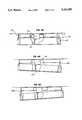
- FIG. 2is a side view, partly broken away, illustrating structural aspects of the present invention
- FIGS. 3A and 3Bare enlarged, partial, schematic end views of a blocking structure in accordance with the present invention illustrating the missing battery and the battery present conditions respectively;
- FIG. 4is a perspective view of an ionization-type smoke detector in accordance with the present invention.
- FIG. 5is a side view, partly broken away, of the detector of FIG. 4 mounted on a ceiling;
- FIGS. 6A, 6B, and 6Cillustrate an alternate embodiment of a unit with a removable cover in accordance with the present invention with each view partly broken away.
- FIG. 1illustrates a detector 10 in accordance with the present invention.
- the detector 10includes a base 12 with a cover 14.
- the cover 14is illustrated in FIG. 1 as being attached by hinge 16 to the cover 14. It will be understood that the present invention is not limited to covers which are pivotably or hingedly attached to a base.
- the unit 20can be any conventional condition sensing detector.
- the detector 10can be exclusively a battery power detector wherein the associated battery would be positioned between the members 24 and 26. Alternately, the detector 10 can be an AC powered unit with battery backup. In such an instance the battery would also be positioned between the members 24 and 26.
- Each of the members 24 and 26is affixed at a first end, respectively 24a and 26a, to the base 12. Each has a free end respectively, 24b and 26b.
- the members 24 and 26can be formed of a resilient plastic and be integrally molded with the base 12.
- FIG. 1Illustrated in FIG. 1 is the relative position of the members 24, 26 with respect to one another in the absence of an energizing battery B. In this condition the free ends 24b and 26b have moved relatively toward one another. As discussed in more detail subsequently in the presence of the battery B, the members 24b and 26b move apart from one another.
- the cover 14carries a rigid, generally rectangular, blocking member 28.
- the member 28is affixed at a first end 28a to the cover 14.
- the member 28also has a free edge 28b which is displaced from the cover 14.
- the member 28can be integrally molded with the cover 14.
- the base 12 and cover 14respectively carry a recess 30 and latch 32.
- the latch 32engages in the recess 30.
- the cover 14can thus be releasably coupled to the base 12.
- the base 12 of the unit 10is to be attached, as is conventional, to a ceiling C.
- the cover 14When so mounted if the cover 14 is not latched to the base 12, it will hang open under the influence of gravity as illustrated in phantom at 14a.
- FIGS. 3A and 3Billustrate the relationship of the battery retaining members 24 and 26 with respect to the blocking member 28 in the battery missing and the battery present conditions respectively.
- the free ends 24b and 26b of the battery retaining members 24 and 26move inwardly with respect to one another.
- the free edge 28b of the blocking member 28comes into contact with and is blocked by surfaces on the free ends 24b and 26b.
- the free ends 24b and 26bcarry pointed end areas 24c and 26c.
- the end areasblockingly engage V-shaped notches 30a and 30b in the member 28.
- FIG. 3Billustrates the battery present condition wherein the members 24 and 26 have the battery B located therebetween.
- the free ends 24b and 26b as a resulthave moved apart from one another.
- the blocking member 28passes between free ends 24b and 26b permitting the cover 14 to move against the base 12 and latch thereto.
- the cover 14will be closed against and latched to the base 12.
- free ends 24b and 26b and blocking member 28could have an uninterrupted or straight free edge without any V-shaped notches such as 30a and 30b therein.
- the free ends 24b and 26bcould terminate in square ends, indicated in phantom in FIG. 3B by edges 32a and 32b. Irrespective of the exact shape of the blocking member 28 and the end regions 24b and 26b, so long as the member 28 comes in blocking contact with the end regions 24b and 26b in the absence of the battery B, such variations in shape are within the spirit and scope of the present invention.
- FIG. 4illustrates a smoke detector 40 in accordance with the present invention.
- the detector 40has a base 42 and a hingedly mounted cover 44.
- the base 42carries a conventional ionization-type detection apparatus generally indicated at 46.
- first and second battery retaining prongs 48 and 50are also on the base 42.
- the cover 44carries a blocking flange 52.
- the cover 44can be latched to the base 42 by a latch member 54 carried on the base 42 which releasably engages a latch notch 56 carried on the cover 44.
- the blocking flange 52drops between the battery retaining prongs 48 and 50 allowing the latch 54 to engage the latch retaining recess 56 in the cover 44. In the absence of a battery the blocking flange 52 comes into contact with the free ends of the battery retaining members 48 and 50 and the cover 44 is blocked from closing thereby as illustrated generally in FIG. 3A.
- FIG. 5illustrates the detector 40 mounted on a ceiling C as is conventional.
- the cover 44will hang open in the absence of a battery providing a visual indication of that absence. With the battery present, the cover 44 can be latched closed against the base 42.
- FIGS. 6A, 6B and 6Cillustrate an alternate embodiment 60.
- the embodiment 60includes a base 62 which can be affixed to a ceiling or wall surface S.
- the unit 60also includes a cover 64.
- the cover 64can be latched to the base 62 in the presence of a battery B as illustrated in FIG. 6A.
- FIGS. 6B and 6Cwhen the battery B is missing from the base 62 the latch members 66a and 66b carried thereon cannot simultaneously engage the cover 64. The engagement is blocked by flange 68 which intersects first and second battery prongs 70a and 70b, of which only 70a is illustrated.
- the prongs 70a and 70bare the same general type prongs as illustrated previously in FIG. 1 as prongs 24 and 26.
Landscapes
- Physics & Mathematics (AREA)
- General Physics & Mathematics (AREA)
- Business, Economics & Management (AREA)
- Emergency Management (AREA)
- Engineering & Computer Science (AREA)
- Analytical Chemistry (AREA)
- Chemical & Material Sciences (AREA)
- Computer Security & Cryptography (AREA)
- Fire-Detection Mechanisms (AREA)
- Battery Mounting, Suspending (AREA)
- Secondary Cells (AREA)
- Fire Alarms (AREA)
- Emergency Alarm Devices (AREA)
Abstract
Description
Claims (2)
Priority Applications (5)
| Application Number | Priority Date | Filing Date | Title |
|---|---|---|---|
| US07/485,221US5191855A (en) | 1990-02-26 | 1990-02-26 | Battery missing indicator |
| DE69018441TDE69018441T2 (en) | 1990-02-26 | 1990-06-18 | Indicator of the lack of a battery. |
| EP90111466AEP0445346B1 (en) | 1990-02-26 | 1990-06-18 | Battery missing indicator |
| CA002020025ACA2020025C (en) | 1990-02-26 | 1990-06-27 | Battery missing indicator |
| JP2183873AJPH03254062A (en) | 1990-02-26 | 1990-07-11 | Indicator deprived of battery |
Applications Claiming Priority (1)
| Application Number | Priority Date | Filing Date | Title |
|---|---|---|---|
| US07/485,221US5191855A (en) | 1990-02-26 | 1990-02-26 | Battery missing indicator |
Publications (1)
| Publication Number | Publication Date |
|---|---|
| US5191855Atrue US5191855A (en) | 1993-03-09 |
Family
ID=23927367
Family Applications (1)
| Application Number | Title | Priority Date | Filing Date |
|---|---|---|---|
| US07/485,221Expired - LifetimeUS5191855A (en) | 1990-02-26 | 1990-02-26 | Battery missing indicator |
Country Status (5)
| Country | Link |
|---|---|
| US (1) | US5191855A (en) |
| EP (1) | EP0445346B1 (en) |
| JP (1) | JPH03254062A (en) |
| CA (1) | CA2020025C (en) |
| DE (1) | DE69018441T2 (en) |
Cited By (43)
| Publication number | Priority date | Publication date | Assignee | Title |
|---|---|---|---|---|
| US5646598A (en)* | 1995-05-02 | 1997-07-08 | Nickles; Aaron Michael | Smoke detector with advanced safety features |
| US6160487A (en)* | 1999-07-22 | 2000-12-12 | Kidde Walter Portable Equipment Inc | Single lockout mechanism for a multiple battery compartment that is particularly suited for smoke and carbon monoxide detector apparatus |
| US6446926B1 (en)* | 2001-01-26 | 2002-09-10 | Thomas J. Kaschuk | Smoke alarm retaining apparatus |
| US20040229113A1 (en)* | 2003-03-10 | 2004-11-18 | Walter Kidde Portable Equipment, Inc. | Pivoting battery carrier and a life safety device incorporating the same |
| US20070049870A1 (en)* | 2001-05-18 | 2007-03-01 | Deka Products Limited Partnership | Infusion Set for a Fluid Pump |
| US20070219496A1 (en)* | 2006-02-09 | 2007-09-20 | Dean Kamen | Pumping fluid delivery systems and methods using force application assembly |
| US20090099523A1 (en)* | 2001-05-18 | 2009-04-16 | Grant Kevin L | Infusion pump assembly |
| US20090275896A1 (en)* | 2007-02-09 | 2009-11-05 | Dean Kamen | Infusion pump assembly |
| US20090281497A1 (en)* | 2007-12-31 | 2009-11-12 | Dean Kamen | Wearable pump assembly |
| US20100094222A1 (en)* | 2008-10-10 | 2010-04-15 | Grant Kevin L | Infusion pump assembly |
| US20100089475A1 (en)* | 2008-10-10 | 2010-04-15 | Tracey Brian D | Medium connector |
| US20100094215A1 (en)* | 2008-10-10 | 2010-04-15 | Grant Kevin L | Pump assembly with a removable cover assembly |
| US7799991B1 (en) | 2007-10-31 | 2010-09-21 | Yazaki North America, Inc. | Bus bar position assurance device |
| US20110074594A1 (en)* | 2009-09-29 | 2011-03-31 | Tyco Healthcare Group Lp | Battery Assembly With Alarm |
| US20110232561A1 (en)* | 2007-12-20 | 2011-09-29 | Cooper Technologies Company | Indicating Devices and Associated Methods |
| US8066672B2 (en) | 2008-10-10 | 2011-11-29 | Deka Products Limited Partnership | Infusion pump assembly with a backup power supply |
| US8223028B2 (en) | 2008-10-10 | 2012-07-17 | Deka Products Limited Partnership | Occlusion detection system and method |
| US8267892B2 (en) | 2008-10-10 | 2012-09-18 | Deka Products Limited Partnership | Multi-language / multi-processor infusion pump assembly |
| US9180245B2 (en) | 2008-10-10 | 2015-11-10 | Deka Products Limited Partnership | System and method for administering an infusible fluid |
| US9494476B2 (en) | 2007-12-20 | 2016-11-15 | Cooper Technologies Company | Indicator device for an enclosure with sealing compound |
| CN110065561A (en)* | 2019-04-25 | 2019-07-30 | 潍坊红石星机械加工有限公司 | The anti-theft device for battery of electro-tricycle |
| US11364335B2 (en) | 2006-02-09 | 2022-06-21 | Deka Products Limited Partnership | Apparatus, system and method for fluid delivery |
| US11395877B2 (en) | 2006-02-09 | 2022-07-26 | Deka Products Limited Partnership | Systems and methods for fluid delivery |
| US11404776B2 (en) | 2007-12-31 | 2022-08-02 | Deka Products Limited Partnership | Split ring resonator antenna adapted for use in wirelessly controlled medical device |
| US11426512B2 (en) | 2006-02-09 | 2022-08-30 | Deka Products Limited Partnership | Apparatus, systems and methods for an infusion pump assembly |
| US11478623B2 (en) | 2006-02-09 | 2022-10-25 | Deka Products Limited Partnership | Infusion pump assembly |
| US11497686B2 (en) | 2007-12-31 | 2022-11-15 | Deka Products Limited Partnership | Apparatus, system and method for fluid delivery |
| US11497846B2 (en) | 2006-02-09 | 2022-11-15 | Deka Products Limited Partnership | Patch-sized fluid delivery systems and methods |
| WO2022241075A1 (en)* | 2021-05-14 | 2022-11-17 | SimpliSafe, Inc. | Battery tamper indicator for detector |
| US11523972B2 (en) | 2018-04-24 | 2022-12-13 | Deka Products Limited Partnership | Apparatus, system and method for fluid delivery |
| US11524151B2 (en) | 2012-03-07 | 2022-12-13 | Deka Products Limited Partnership | Apparatus, system and method for fluid delivery |
| US11534542B2 (en) | 2007-12-31 | 2022-12-27 | Deka Products Limited Partnership | Apparatus, system and method for fluid delivery |
| US11597541B2 (en) | 2013-07-03 | 2023-03-07 | Deka Products Limited Partnership | Apparatus, system and method for fluid delivery |
| US11642283B2 (en) | 2007-12-31 | 2023-05-09 | Deka Products Limited Partnership | Method for fluid delivery |
| US11723841B2 (en) | 2007-12-31 | 2023-08-15 | Deka Products Limited Partnership | Apparatus, system and method for fluid delivery |
| US11890448B2 (en) | 2006-02-09 | 2024-02-06 | Deka Products Limited Partnership | Method and system for shape-memory alloy wire control |
| US11964126B2 (en) | 2006-02-09 | 2024-04-23 | Deka Products Limited Partnership | Infusion pump assembly |
| US12064590B2 (en) | 2006-02-09 | 2024-08-20 | Deka Products Limited Partnership | Patch-sized fluid delivery systems and methods |
| US12070574B2 (en) | 2006-02-09 | 2024-08-27 | Deka Products Limited Partnership | Apparatus, systems and methods for an infusion pump assembly |
| US12151080B2 (en) | 2006-02-09 | 2024-11-26 | Deka Products Limited Partnership | Adhesive and peripheral systems and methods for medical devices |
| US12186531B2 (en) | 2008-10-10 | 2025-01-07 | Deka Products Limited Partnership | Infusion pump assembly |
| US12274857B2 (en) | 2006-02-09 | 2025-04-15 | Deka Products Limited Partnership | Method and system for shape-memory alloy wire control |
| US12370327B2 (en) | 2008-10-10 | 2025-07-29 | Deka Products Limited Partnership | Infusion pump methods, systems and apparatus |
Families Citing this family (6)
| Publication number | Priority date | Publication date | Assignee | Title |
|---|---|---|---|---|
| JP2606954B2 (en)* | 1990-08-30 | 1997-05-07 | シャープ株式会社 | Battery storage structure |
| GB2420899A (en)* | 2004-12-06 | 2006-06-07 | Peter Frost-Gaskin | Smoke alarm housing |
| JP4676524B2 (en)* | 2008-10-22 | 2011-04-27 | 能美防災株式会社 | Fire alarm |
| JP5923758B2 (en)* | 2012-06-28 | 2016-05-25 | パナソニックIpマネジメント株式会社 | Battery powered sensor |
| FR3004061B1 (en)* | 2013-03-26 | 2015-03-27 | Hager Security | BOX COMPRISING TWO ARTICULATED PARTS HAVING LATCHING MEANS |
| CN107074372B (en) | 2016-11-02 | 2019-03-29 | 深圳市大疆创新科技有限公司 | A battery storage device and drone |
Citations (8)
| Publication number | Priority date | Publication date | Assignee | Title |
|---|---|---|---|---|
| DE2836233A1 (en)* | 1977-08-19 | 1979-02-22 | Hochiki Co | FIRE DETECTORS, IN PARTICULAR HOUSEHOLD IONIZATION FIRE DETECTORS |
| US4227191A (en)* | 1978-02-21 | 1980-10-07 | Samuel Raber | Light emitting smoke detector |
| US4228428A (en)* | 1979-04-02 | 1980-10-14 | Niedermeyer Karl O | Visible signal for alarm, such as a smoke detector |
| US4525703A (en)* | 1982-08-23 | 1985-06-25 | General Electric Company | Portable smoke alarm |
| US4533904A (en)* | 1984-02-27 | 1985-08-06 | Steinman Jr Leroy F | Combination smoke and burglar alarm |
| US4870395A (en)* | 1988-03-10 | 1989-09-26 | Seatt Corporation | Battery powered smoke alarm safety lockout system |
| US4881063A (en)* | 1989-01-30 | 1989-11-14 | Ei Company, Ltd. | Battery removal indicator |
| US5055830A (en)* | 1989-06-12 | 1991-10-08 | Pittway Corporation | Battery sensing mechanism |
Family Cites Families (1)
| Publication number | Priority date | Publication date | Assignee | Title |
|---|---|---|---|---|
| US3529567A (en)* | 1968-09-06 | 1970-09-22 | Detection Ltd | Mechanical fire detection alarm device |
- 1990
- 1990-02-26USUS07/485,221patent/US5191855A/ennot_activeExpired - Lifetime
- 1990-06-18EPEP90111466Apatent/EP0445346B1/ennot_activeExpired - Lifetime
- 1990-06-18DEDE69018441Tpatent/DE69018441T2/ennot_activeExpired - Lifetime
- 1990-06-27CACA002020025Apatent/CA2020025C/ennot_activeExpired - Lifetime
- 1990-07-11JPJP2183873Apatent/JPH03254062A/enactivePending
Patent Citations (8)
| Publication number | Priority date | Publication date | Assignee | Title |
|---|---|---|---|---|
| DE2836233A1 (en)* | 1977-08-19 | 1979-02-22 | Hochiki Co | FIRE DETECTORS, IN PARTICULAR HOUSEHOLD IONIZATION FIRE DETECTORS |
| US4227191A (en)* | 1978-02-21 | 1980-10-07 | Samuel Raber | Light emitting smoke detector |
| US4228428A (en)* | 1979-04-02 | 1980-10-14 | Niedermeyer Karl O | Visible signal for alarm, such as a smoke detector |
| US4525703A (en)* | 1982-08-23 | 1985-06-25 | General Electric Company | Portable smoke alarm |
| US4533904A (en)* | 1984-02-27 | 1985-08-06 | Steinman Jr Leroy F | Combination smoke and burglar alarm |
| US4870395A (en)* | 1988-03-10 | 1989-09-26 | Seatt Corporation | Battery powered smoke alarm safety lockout system |
| US4881063A (en)* | 1989-01-30 | 1989-11-14 | Ei Company, Ltd. | Battery removal indicator |
| US5055830A (en)* | 1989-06-12 | 1991-10-08 | Pittway Corporation | Battery sensing mechanism |
Non-Patent Citations (4)
| Title |
|---|
| Honeywell Publication, published Jun., 1977 Form No. 60 2347 4.* |
| Honeywell Publication, published Jun., 1977 Form No. 60-2347-4. |
| Honeywell Publication, published Sep. 1978, Form No. 60 2465.* |
| Honeywell Publication, published Sep. 1978, Form No. 60-2465. |
Cited By (95)
| Publication number | Priority date | Publication date | Assignee | Title |
|---|---|---|---|---|
| US5646598A (en)* | 1995-05-02 | 1997-07-08 | Nickles; Aaron Michael | Smoke detector with advanced safety features |
| US6160487A (en)* | 1999-07-22 | 2000-12-12 | Kidde Walter Portable Equipment Inc | Single lockout mechanism for a multiple battery compartment that is particularly suited for smoke and carbon monoxide detector apparatus |
| US6446926B1 (en)* | 2001-01-26 | 2002-09-10 | Thomas J. Kaschuk | Smoke alarm retaining apparatus |
| US20090099523A1 (en)* | 2001-05-18 | 2009-04-16 | Grant Kevin L | Infusion pump assembly |
| US20070049870A1 (en)* | 2001-05-18 | 2007-03-01 | Deka Products Limited Partnership | Infusion Set for a Fluid Pump |
| US9173996B2 (en) | 2001-05-18 | 2015-11-03 | Deka Products Limited Partnership | Infusion set for a fluid pump |
| US8034026B2 (en) | 2001-05-18 | 2011-10-11 | Deka Products Limited Partnership | Infusion pump assembly |
| US20040229113A1 (en)* | 2003-03-10 | 2004-11-18 | Walter Kidde Portable Equipment, Inc. | Pivoting battery carrier and a life safety device incorporating the same |
| US7948389B2 (en) | 2003-03-10 | 2011-05-24 | Walter Kidde Portable Equipment, Inc. | Pivoting battery carrier and a life safety device incorporating the same |
| US20080316044A1 (en)* | 2003-03-10 | 2008-12-25 | Walter Kidde Portable Equipment, Inc. | Pivoting Battery Carrier and a Life Safety Device Incorporating the Same |
| US7492273B2 (en) | 2003-03-10 | 2009-02-17 | Walter Kidde Portable Equipment, Inc. | Pivoting battery carrier and a life safety device incorporating the same |
| US11712513B2 (en) | 2006-02-09 | 2023-08-01 | Deka Products Limited Partnership | Adhesive and peripheral systems and methods for medical devices |
| US11738139B2 (en) | 2006-02-09 | 2023-08-29 | Deka Products Limited Partnership | Patch-sized fluid delivery systems and methods |
| US12311143B2 (en) | 2006-02-09 | 2025-05-27 | Deka Products Limited Partnership | Adhesive and peripheral systems and methods for medical devices |
| US12274857B2 (en) | 2006-02-09 | 2025-04-15 | Deka Products Limited Partnership | Method and system for shape-memory alloy wire control |
| US12233236B2 (en) | 2006-02-09 | 2025-02-25 | Deka Products Limited Partnership | Adhesive and peripheral systems and methods for medical devices |
| US12151080B2 (en) | 2006-02-09 | 2024-11-26 | Deka Products Limited Partnership | Adhesive and peripheral systems and methods for medical devices |
| US12070574B2 (en) | 2006-02-09 | 2024-08-27 | Deka Products Limited Partnership | Apparatus, systems and methods for an infusion pump assembly |
| US12064590B2 (en) | 2006-02-09 | 2024-08-20 | Deka Products Limited Partnership | Patch-sized fluid delivery systems and methods |
| US12036387B2 (en) | 2006-02-09 | 2024-07-16 | Deka Products Limited Partnership | Device to determine volume of fluid dispensed |
| US20070228071A1 (en)* | 2006-02-09 | 2007-10-04 | Dean Kamen | Fluid delivery systems and methods |
| US11992650B2 (en) | 2006-02-09 | 2024-05-28 | Deka Products Limited Partnership | Adhesive and peripheral systems and methods for medical devices |
| US11964126B2 (en) | 2006-02-09 | 2024-04-23 | Deka Products Limited Partnership | Infusion pump assembly |
| US20070219480A1 (en)* | 2006-02-09 | 2007-09-20 | Dean Kamen | Patch-sized fluid delivery systems and methods |
| US11904134B2 (en) | 2006-02-09 | 2024-02-20 | Deka Products Limited Partnership | Patch-sized fluid delivery systems and methods |
| US8113244B2 (en) | 2006-02-09 | 2012-02-14 | Deka Products Limited Partnership | Adhesive and peripheral systems and methods for medical devices |
| US11890448B2 (en) | 2006-02-09 | 2024-02-06 | Deka Products Limited Partnership | Method and system for shape-memory alloy wire control |
| US11844926B2 (en) | 2006-02-09 | 2023-12-19 | Deka Products Limited Partnership | Adhesive and peripheral systems and methods for medical devices |
| US11786651B2 (en) | 2006-02-09 | 2023-10-17 | Deka Products Limited Partnership | Patch-sized fluid delivery system |
| US11717609B2 (en) | 2006-02-09 | 2023-08-08 | Deka Products Limited Partnership | Adhesive and peripheral systems and methods for medical devices |
| US20070219496A1 (en)* | 2006-02-09 | 2007-09-20 | Dean Kamen | Pumping fluid delivery systems and methods using force application assembly |
| US8414522B2 (en) | 2006-02-09 | 2013-04-09 | Deka Products Limited Partnership | Fluid delivery systems and methods |
| US11690952B2 (en) | 2006-02-09 | 2023-07-04 | Deka Products Limited Partnership | Pumping fluid delivery systems and methods using force application assembly |
| US11617826B2 (en) | 2006-02-09 | 2023-04-04 | Deka Products Limited Partnership | Patch-sized fluid delivery systems and methods |
| US11559625B2 (en) | 2006-02-09 | 2023-01-24 | Deka Products Limited Partnership | Patch-sized fluid delivery systems and methods |
| US8545445B2 (en) | 2006-02-09 | 2013-10-01 | Deka Products Limited Partnership | Patch-sized fluid delivery systems and methods |
| US8585377B2 (en) | 2006-02-09 | 2013-11-19 | Deka Products Limited Partnership | Pumping fluid delivery systems and methods using force application assembly |
| US11534543B2 (en) | 2006-02-09 | 2022-12-27 | Deka Products Limited Partnership | Method for making patch-sized fluid delivery systems |
| US11497846B2 (en) | 2006-02-09 | 2022-11-15 | Deka Products Limited Partnership | Patch-sized fluid delivery systems and methods |
| US11491273B2 (en) | 2006-02-09 | 2022-11-08 | Deka Products Limited Partnership | Adhesive and peripheral systems and methods for medical devices |
| US20070219597A1 (en)* | 2006-02-09 | 2007-09-20 | Dean Kamen | Adhesive and peripheral systems and methods for medical devices |
| US11478623B2 (en) | 2006-02-09 | 2022-10-25 | Deka Products Limited Partnership | Infusion pump assembly |
| US11426512B2 (en) | 2006-02-09 | 2022-08-30 | Deka Products Limited Partnership | Apparatus, systems and methods for an infusion pump assembly |
| US11413391B2 (en) | 2006-02-09 | 2022-08-16 | Deka Products Limited Partnership | Patch-sized fluid delivery systems and methods |
| US11408414B2 (en) | 2006-02-09 | 2022-08-09 | Deka Products Limited Partnership | Adhesive and peripheral systems and methods for medical devices |
| US11339774B2 (en) | 2006-02-09 | 2022-05-24 | Deka Products Limited Partnership | Adhesive and peripheral systems and methods for medical devices |
| US11364335B2 (en) | 2006-02-09 | 2022-06-21 | Deka Products Limited Partnership | Apparatus, system and method for fluid delivery |
| US11391273B2 (en) | 2006-02-09 | 2022-07-19 | Deka Products Limited Partnership | Adhesive and peripheral systems and methods for medical devices |
| US11395877B2 (en) | 2006-02-09 | 2022-07-26 | Deka Products Limited Partnership | Systems and methods for fluid delivery |
| US11406753B2 (en) | 2006-02-09 | 2022-08-09 | Deka Products Limited Partnership | Adhesive and peripheral systems and methods for medical devices |
| US20090275896A1 (en)* | 2007-02-09 | 2009-11-05 | Dean Kamen | Infusion pump assembly |
| US8496646B2 (en) | 2007-02-09 | 2013-07-30 | Deka Products Limited Partnership | Infusion pump assembly |
| US7799991B1 (en) | 2007-10-31 | 2010-09-21 | Yazaki North America, Inc. | Bus bar position assurance device |
| US9111425B2 (en)* | 2007-12-20 | 2015-08-18 | Cooper Technologies Company | Indicating devices and associated methods |
| US9494476B2 (en) | 2007-12-20 | 2016-11-15 | Cooper Technologies Company | Indicator device for an enclosure with sealing compound |
| US20110232561A1 (en)* | 2007-12-20 | 2011-09-29 | Cooper Technologies Company | Indicating Devices and Associated Methods |
| US11534542B2 (en) | 2007-12-31 | 2022-12-27 | Deka Products Limited Partnership | Apparatus, system and method for fluid delivery |
| US9526830B2 (en) | 2007-12-31 | 2016-12-27 | Deka Products Limited Partnership | Wearable pump assembly |
| US12128006B2 (en) | 2007-12-31 | 2024-10-29 | Deka Products Limited Partnership | Apparatus, system and method for fluid delivery |
| US12121497B2 (en) | 2007-12-31 | 2024-10-22 | Deka Products Limited Partnership | Method for fluid delivery |
| US11497686B2 (en) | 2007-12-31 | 2022-11-15 | Deka Products Limited Partnership | Apparatus, system and method for fluid delivery |
| US11404776B2 (en) | 2007-12-31 | 2022-08-02 | Deka Products Limited Partnership | Split ring resonator antenna adapted for use in wirelessly controlled medical device |
| US20090281497A1 (en)* | 2007-12-31 | 2009-11-12 | Dean Kamen | Wearable pump assembly |
| US20090299289A1 (en)* | 2007-12-31 | 2009-12-03 | Dean Kamen | Pump assembly with switch |
| US11723841B2 (en) | 2007-12-31 | 2023-08-15 | Deka Products Limited Partnership | Apparatus, system and method for fluid delivery |
| US8491570B2 (en) | 2007-12-31 | 2013-07-23 | Deka Products Limited Partnership | Infusion pump assembly |
| US11642283B2 (en) | 2007-12-31 | 2023-05-09 | Deka Products Limited Partnership | Method for fluid delivery |
| US11894609B2 (en) | 2007-12-31 | 2024-02-06 | Deka Products Limited Partnership | Split ring resonator antenna adapted for use in wirelessly controlled medical device |
| US8414563B2 (en) | 2007-12-31 | 2013-04-09 | Deka Products Limited Partnership | Pump assembly with switch |
| US11701300B2 (en) | 2007-12-31 | 2023-07-18 | Deka Products Limited Partnership | Method for fluid delivery |
| US12415031B2 (en) | 2007-12-31 | 2025-09-16 | Deka Products Limited Partnership | Wearable pump assembly |
| US8708376B2 (en) | 2008-10-10 | 2014-04-29 | Deka Products Limited Partnership | Medium connector |
| US12370327B2 (en) | 2008-10-10 | 2025-07-29 | Deka Products Limited Partnership | Infusion pump methods, systems and apparatus |
| US20100094222A1 (en)* | 2008-10-10 | 2010-04-15 | Grant Kevin L | Infusion pump assembly |
| US8262616B2 (en) | 2008-10-10 | 2012-09-11 | Deka Products Limited Partnership | Infusion pump assembly |
| US8223028B2 (en) | 2008-10-10 | 2012-07-17 | Deka Products Limited Partnership | Occlusion detection system and method |
| US12186531B2 (en) | 2008-10-10 | 2025-01-07 | Deka Products Limited Partnership | Infusion pump assembly |
| US8267892B2 (en) | 2008-10-10 | 2012-09-18 | Deka Products Limited Partnership | Multi-language / multi-processor infusion pump assembly |
| US20100089475A1 (en)* | 2008-10-10 | 2010-04-15 | Tracey Brian D | Medium connector |
| US8066672B2 (en) | 2008-10-10 | 2011-11-29 | Deka Products Limited Partnership | Infusion pump assembly with a backup power supply |
| US9180245B2 (en) | 2008-10-10 | 2015-11-10 | Deka Products Limited Partnership | System and method for administering an infusible fluid |
| US8016789B2 (en) | 2008-10-10 | 2011-09-13 | Deka Products Limited Partnership | Pump assembly with a removable cover assembly |
| US20100094215A1 (en)* | 2008-10-10 | 2010-04-15 | Grant Kevin L | Pump assembly with a removable cover assembly |
| US20110074594A1 (en)* | 2009-09-29 | 2011-03-31 | Tyco Healthcare Group Lp | Battery Assembly With Alarm |
| US8179276B2 (en)* | 2009-09-29 | 2012-05-15 | Tyco Healthcare Group Lp | Battery assembly with alarm |
| US8373572B2 (en) | 2009-09-29 | 2013-02-12 | Covidien Lp | Battery assembly with alarm |
| US8730053B2 (en) | 2009-09-29 | 2014-05-20 | Covidien Lp | Battery assembly with alarm |
| US11524151B2 (en) | 2012-03-07 | 2022-12-13 | Deka Products Limited Partnership | Apparatus, system and method for fluid delivery |
| US12012241B2 (en) | 2013-07-03 | 2024-06-18 | Deka Products Limited Partnership | Apparatus, system and method for fluid delivery |
| US11597541B2 (en) | 2013-07-03 | 2023-03-07 | Deka Products Limited Partnership | Apparatus, system and method for fluid delivery |
| US11523972B2 (en) | 2018-04-24 | 2022-12-13 | Deka Products Limited Partnership | Apparatus, system and method for fluid delivery |
| CN110065561A (en)* | 2019-04-25 | 2019-07-30 | 潍坊红石星机械加工有限公司 | The anti-theft device for battery of electro-tricycle |
| US11676476B2 (en) | 2021-05-14 | 2023-06-13 | SimpliSafe, Inc. | Battery tamper indicator for detector |
| WO2022241075A1 (en)* | 2021-05-14 | 2022-11-17 | SimpliSafe, Inc. | Battery tamper indicator for detector |
| CN117501331A (en)* | 2021-05-14 | 2024-02-02 | 简单安全有限公司 | Battery change indicator for detectors |
Also Published As
| Publication number | Publication date |
|---|---|
| CA2020025C (en) | 1994-11-08 |
| DE69018441T2 (en) | 1996-01-04 |
| EP0445346A1 (en) | 1991-09-11 |
| CA2020025A1 (en) | 1991-08-27 |
| EP0445346B1 (en) | 1995-04-05 |
| DE69018441D1 (en) | 1995-05-11 |
| JPH03254062A (en) | 1991-11-13 |
Similar Documents
| Publication | Publication Date | Title |
|---|---|---|
| US5191855A (en) | Battery missing indicator | |
| US5055830A (en) | Battery sensing mechanism | |
| US5103216A (en) | Improperly inserted battery detector | |
| US4438428A (en) | Multiple function personal security alarm | |
| US4881063A (en) | Battery removal indicator | |
| AU2008237716B2 (en) | Fire alarm and like devices | |
| US4418336A (en) | Alarm indicating dislocation of fire extinguisher | |
| US5489890A (en) | Portable alarm device for entryway motion monitoring | |
| US4539555A (en) | Fire and smoke protection device for use in buildings | |
| WO2004044859A1 (en) | Warning unit | |
| US7414539B2 (en) | Simple alarm device | |
| US4567477A (en) | Smoke detector switch indicator | |
| CN101283385A (en) | Alarm device and housing for an alarm device | |
| JPH06348975A (en) | Fire alarm | |
| EP0800694B1 (en) | Fire detector identification | |
| JP4284533B2 (en) | Wall-mounted fire alarm | |
| JP3843936B2 (en) | Disaster prevention detector for home | |
| CA1188773A (en) | Smoke detector indicator | |
| CN210129666U (en) | Intelligent cabinet | |
| KR200193017Y1 (en) | Used indicator for public toilet | |
| CN219996355U (en) | Temperature measurement security inspection door | |
| PL327625A1 (en) | Contact pair state determining detector | |
| JP2003099871A (en) | Fire alarm for dwelling house | |
| JPS6022474Y2 (en) | fire detector | |
| KR100457301B1 (en) | Displacement Detection Device |
Legal Events
| Date | Code | Title | Description |
|---|---|---|---|
| AS | Assignment | Owner name:PITTWAY CORPORATION, A PA CORP. Free format text:ASSIGNMENT OF ASSIGNORS INTEREST.;ASSIGNOR:CONFORTI, FRED J.;REEL/FRAME:005437/0575 Effective date:19900330 | |
| STCF | Information on status: patent grant | Free format text:PATENTED CASE | |
| FEPP | Fee payment procedure | Free format text:PAT HOLDER CLAIMS SMALL ENTITY STATUS - SMALL BUSINESS (ORIGINAL EVENT CODE: SM02); ENTITY STATUS OF PATENT OWNER: LARGE ENTITY | |
| FEPP | Fee payment procedure | Free format text:PAT HLDR NO LONGER CLAIMS SMALL ENT STAT AS SMALL BUSINESS (ORIGINAL EVENT CODE: LSM2); ENTITY STATUS OF PATENT OWNER: LARGE ENTITY | |
| FPAY | Fee payment | Year of fee payment:4 | |
| AS | Assignment | Owner name:FIRST NATIONAL BANK OF CHICAGO, THE, ILLINOIS Free format text:ASSIGNMENT OF ASSIGNORS INTEREST;ASSIGNOR:BRK BRANDS, INC.;REEL/FRAME:008321/0141 Effective date:19960903 | |
| FEPP | Fee payment procedure | Free format text:PAYOR NUMBER ASSIGNED (ORIGINAL EVENT CODE: ASPN); ENTITY STATUS OF PATENT OWNER: LARGE ENTITY | |
| FPAY | Fee payment | Year of fee payment:8 | |
| AS | Assignment | Owner name:FIRST UNION NATIONAL BANK, AS ADMINISTRATIVE AGENT Free format text:CONDITIONAL ASSIGNMENT OF AND SECURITY INTEREST IN PATENT RIGHTS;ASSIGNOR:BRK BRANDS, INC.;REEL/FRAME:011007/0956 Effective date:20001005 | |
| AS | Assignment | Owner name:FIRST UNION NATIONAL BANK, AS ADMINISTRATIVE AGENT Free format text:SECURITY INTEREST;ASSIGNOR:BRK BRANDS, INC. (DE CORPORATION);REEL/FRAME:011111/0190 Effective date:20000929 | |
| AS | Assignment | Owner name:BRK BRANDS, INC., ILLINOIS Free format text:TERMINATION AND RELEASE OF SECURITY INTEREST;ASSIGNOR:WACHOVIA BANK, NATIONAL ASSOCIATION, FORMERLY FIRST UNION NATIONAL BANK;REEL/FRAME:014015/0215 Effective date:20021213 | |
| AS | Assignment | Owner name:GENERAL ELECTRIC CAPITAL CORPORATION, GEORGIA Free format text:INTELLECTUAL PROPERTY SECURITY AGREEMENT;ASSIGNORS:COLEMAN COMPANY, INC., THE;COLEMAN POWERMATE, INC.;BRK BRANDS, INC.;AND OTHERS;REEL/FRAME:014027/0767 Effective date:20021213 | |
| FPAY | Fee payment | Year of fee payment:12 |