US5190547A - Replicator for resecting bone to match a pattern - Google Patents
Replicator for resecting bone to match a patternDownload PDFInfo
- Publication number
- US5190547A US5190547AUS07/883,685US88368592AUS5190547AUS 5190547 AUS5190547 AUS 5190547AUS 88368592 AUS88368592 AUS 88368592AUS 5190547 AUS5190547 AUS 5190547A
- Authority
- US
- United States
- Prior art keywords
- holder
- bone
- pattern
- tool holder
- frame
- Prior art date
- Legal status (The legal status is an assumption and is not a legal conclusion. Google has not performed a legal analysis and makes no representation as to the accuracy of the status listed.)
- Expired - Lifetime
Links
- 210000000988bone and boneAnatomy0.000titleclaimsabstractdescription95
- 239000000523sampleSubstances0.000claimsabstractdescription30
- 238000000034methodMethods0.000claims1
- 238000002271resectionMethods0.000abstractdescription3
- 210000000689upper legAnatomy0.000description7
- 238000001356surgical procedureMethods0.000description4
- 239000007943implantSubstances0.000description2
- 239000000463materialSubstances0.000description2
- 230000000007visual effectEffects0.000description2
- 210000000629knee jointAnatomy0.000description1
- 210000002414legAnatomy0.000description1
- 230000000399orthopedic effectEffects0.000description1
Images


Classifications
- A—HUMAN NECESSITIES
- A61—MEDICAL OR VETERINARY SCIENCE; HYGIENE
- A61B—DIAGNOSIS; SURGERY; IDENTIFICATION
- A61B17/00—Surgical instruments, devices or methods
- A61B17/16—Instruments for performing osteoclasis; Drills or chisels for bones; Trepans
- A61B17/17—Guides or aligning means for drills, mills, pins or wires
- A—HUMAN NECESSITIES
- A61—MEDICAL OR VETERINARY SCIENCE; HYGIENE
- A61B—DIAGNOSIS; SURGERY; IDENTIFICATION
- A61B17/00—Surgical instruments, devices or methods
- A61B17/16—Instruments for performing osteoclasis; Drills or chisels for bones; Trepans
- A—HUMAN NECESSITIES
- A61—MEDICAL OR VETERINARY SCIENCE; HYGIENE
- A61B—DIAGNOSIS; SURGERY; IDENTIFICATION
- A61B17/00—Surgical instruments, devices or methods
- A61B17/16—Instruments for performing osteoclasis; Drills or chisels for bones; Trepans
- A61B17/1662—Instruments for performing osteoclasis; Drills or chisels for bones; Trepans for particular parts of the body
- A61B17/1675—Instruments for performing osteoclasis; Drills or chisels for bones; Trepans for particular parts of the body for the knee
- A—HUMAN NECESSITIES
- A61—MEDICAL OR VETERINARY SCIENCE; HYGIENE
- A61B—DIAGNOSIS; SURGERY; IDENTIFICATION
- A61B17/00—Surgical instruments, devices or methods
- A61B17/16—Instruments for performing osteoclasis; Drills or chisels for bones; Trepans
- A61B17/17—Guides or aligning means for drills, mills, pins or wires
- A61B17/1739—Guides or aligning means for drills, mills, pins or wires specially adapted for particular parts of the body
- A61B17/1764—Guides or aligning means for drills, mills, pins or wires specially adapted for particular parts of the body for the knee
- A—HUMAN NECESSITIES
- A61—MEDICAL OR VETERINARY SCIENCE; HYGIENE
- A61B—DIAGNOSIS; SURGERY; IDENTIFICATION
- A61B17/00—Surgical instruments, devices or methods
- A61B17/16—Instruments for performing osteoclasis; Drills or chisels for bones; Trepans
- A61B2017/1602—Mills
Definitions
- This inventionrelates in general to equipment for resecting bones during implant and prosthetic surgery so as to match a pattern.
- portions of the donor bone jointmust be shaped to resemble the diseased bone joint as much as possible.
- a tibial plateau prosthesismay be implanted in the leg of a user while retaining an existing femur.
- the existing femurmust be resected to match the tibial plateau of the prosthesis as much as possible.
- a replicator apparatusfor resecting the bone into a desired shape is provided that will precisely shape the bone to the pattern.
- the replicatorincludes a frame with a pattern holder and a bone holder.
- the pattern holder and the bone holderare spaced apart from each other on an X-axis, or bone-pattern axis.
- a tool holderholds a probe and a power cutting tool. The tips of the probe and the cutting tool are mounted on a line that is parallel to the tool holder axis.
- a linkage meansconnects the tool holder with structure mounted to the frame.
- the linkage meanscomprises two pairs of parallel bars, each forming parallelograms. These bars are pivotally mounted so as to allow free movement in three dimensions of the tool holder. However, the bars will always maintain the tool holder parallel to the bone-pattern axis. The user traces the tip of the probe over the pattern while operating the cutting tool to shape the bone to match the pattern.
- FIG. 1is a perspective view showing a first embodiment of a replicator apparatus constructed in accordance with this invention.
- FIG. 2is a side view of the replicator of FIG. 1.
- FIG. 3is a front view of a portion of the replicator of FIG. 1.
- FIG. 4is a perspective view illustrating a second embodiment of a replicator apparatus constructed in accordance with this invention.
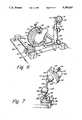
- FIG. 5is a perspective view of a third embodiment of a replicator apparatus constructed in accordance with this invention.
- FIG. 6is a perspective view of the bone holder and pattern holder of the replicator of FIG. 5.
- FIG. 7is a perspective view of the bone holder of the replicator of FIG. 5.
- replicator 11is constructed to be utilized in an operating room during surgery.
- Resecting replicator 11has an L-shaped frame 13 which mounts to a vertical rod 12.
- Frame 13has a horizontal or X-axis portion 13a, extending along an X-axis 14 and a vertical or Y-axis portion 13b, extending along a Y-axis 16.
- a bone holder means 15having an axis perpendicular to X-axis 14 is mounted to frame 13.
- Bone holder 15is a circular rotatable plate that has three screw clamps 17. Screw clamps 17 are spaced 120 degrees apart from each other for tightening against a section of a bone 19. In the embodiment of FIGS.
- bone 19will be a section of a donor bone for implanting in a human body.
- bone 19may be a femur of a knee joint.
- bone holder 15can be rotated relative to frame 13 about the axis of bone holder 15.
- a pattern holder 21is spaced from bone holder 15 along the X-axis 14.
- Pattern holder 21is also a plate, having three screw clamps 23 for clamping a pattern 25.
- the axis of pattern holder 21will be perpendicular to and intersecting X-axis 14.
- pattern 25will be a mold formed by the surgeon during surgery.
- a clevis 29mounts to the lower end of the frame vertical portion 13b.
- Clevis 29mounts to a pair of shafts 31, as illustrated also in FIG. 2.
- Clevis 29is not rotatable relative to frame 13.
- a threaded rod 33 having a crank handle 35,will move clevis 29 forward and away from frame 13
- Shafts 31extend along a Z-axis which is perpendicular to X-axis 14 and also to Y-axis 16.
- a vertical line along the Y-axis 16 passing through shafts 31would pass through the center of pattern 25.
- Clevis 29includes a rotatable clevis bracket 37.
- Clevis bracket 37is secured by a pin 39 to spaced apart lobes of clevis 29.
- Pin 39is mounted along a clevis axis that is parallel to X-axis 14 and perpendicular to shafts 31. Pin 39 allows clevis bracket 37 to swing in a Z-axis plane.
- a pair of frame parallel bars 41pivotally mount to clevis bracket 37.
- Frame parallel bars 41are identical in length and size and mounted so as to always be parallel to each other.
- Frame parallel bars 41each have a frame end mounted pivotally to clevis bracket 37 by spaced apart clevis bracket pivot pins 43.
- Pivot pins 43are spaced apart from each other along the Y-axis 16. Pivot pins 43 allow rotation of frame parallel bars 41 in a plane containing frame parallel bars 41.
- the opposite ends, or plate ends, of frame parallel bars 41connect to a linkage plate 45.
- Plate 45is free floating and has four pivotal pins, referred to herein as a zero degree pin 47, a 90 degree pin 49, a 180 degree pin 51, and 270 degree pin 53.
- the zero degree pin 47 and the 180 degree pin 51Will always be located on a line parallel to a plane containing Y-axis 16.
- the 90 degree pin 49 and 270 degree pin 53will always be located on a line parallel to X-axis 14.
- the frame parallel bars 41connect to the zero degree pin 47 and 180 degree pin 51. In the embodiment shown, the ends of the frame parallel bars 41 are located on the side of plate 45 that faces frame 13.
- a pair of tool holder parallel bars 55have plate ends that connects to the 90 degree pin 49 and 270 degree pin 53.
- Tool holder parallel bars 55are of identical length and are maintained always in parallel relationship to each other.
- the ends of tool holder parallel bars 55are located on a side of plate 45 that faces away from frame 13.
- Tool holder parallel bars 55pivotally connect to tool holder pivot pins 57 of a tool holder 59.
- the distance between pivot pins 57is the same as the distance between pivot pins 49 and 53. Similarly, this distance is the same as between pivot pins 47, 51 and the pivot pins 43.
- Tool holder 59includes a tool holder sleeve 61 which supports pivot pins 57.
- An extension member 63extends completely through tool holder sleeve 61. Extension member 63 extends on opposite sides of sleeve 61 and is rotatable relative to sleeve 61.
- a tool holder axisextends along extension member 63. The tool holder axis is maintained by the parallel bars 41, 55 in a parallel relationship to X-axis 14 at all times.
- a stylus or probe 65mounts to the right side of extension sleeve 61. Probe 65 is frictionally held in a hole extending through extension member 63. Probe 65 has a tip 67 that will trace over the contour of pattern 25. The tip 67 will be placed such that when touching the pattern 25, the clevis bracket 37 will be in a near vertical orientation.
- Cutting tool 69is secured in a hole provided in extension member 63 on the opposite side of sleeve 61.
- Cutting tool 69is a conventional high speed pneumatic cutting instrument.
- Cutting tool 69has a tip 71 that will contain a bit or other type of cutting tool for resecting the bone 19.
- Tip 71is spaced apart from tip 67 the same distance as from the centerline of bone holder 15 to the centerline of pattern holder 21.
- probe tip 67will be positioned so that a line passing through tips 67, 71 will be parallel with the axis of tool holder 59 and also parallel with X-axis 14.
- An air hose 73applies air pressure to cutting tool 69 to form the cutting action.
- the surgeonwill make a mold to form a pattern 25. This may be done by first cutting the diseased bone from the patient, then pressing a moldable material against the cut area in the patient. The material will harden into pattern 25, which is then placed in pattern holder 21. The surgeon takes the donor bone 19 and places it in bone holder 15. The surgeon will align the tips 67, 71 parallel with the axis of tool holder 59 by using a T-shaped template (not shown). The surgeon will rotate the crank handle 35 (FIG. 2) to extend clevis 29 to a desired orientation. In that orientation, probe tip 67 will be touching pattern 25, cutting tool 69 will be touching bone 19, and clevis bracket 37 will be oriented approximately parallel to Y-axis 16.
- the surgeonwill turn on cutting tool 69 to begin resecting bone 19.
- the surgeonwill trace probe tip 67 over all portions of the contour of pattern 25.
- the parallel bars 41, 55will allow the tool holder 59 to rotate freely in a plane parallel to the planes containing the parallel bars 41, 55.
- the clevis bracket 37will allow the tool holder 59 to rotate about clevis bracket pin 39 in Z-axis directions. This provides three-dimensional movement.
- the parallel bars 41, 55construct the tool holder 59 such that the tool holder 59 will always be parallel to the X-axis 14. This assures that the section on the bone 19 will precisely match the pattern 25.
- the surgeonwill remove donor bone 19 and implant it in the patient.
- FIG. 4illustrates an alternate embodiment.
- the resecting replicatoris the same in most of its components, therefore these will not be discussed. It differs in that the pattern 75 will be a pattern based on a prosthesis to be installed in the patient. In this case, thigh support 77 will support the thigh 79 of the patient. The patient's femur 81 will be exposed. The surgeon will resect the patient's femur 81 so as to match pattern 75, which matches a tibial plateau to be installed. The tibial plateau is a prostheses.
- FIGS. 5-7show a third embodiment, which performs the same functions as replicator 11 of FIGS. 1-3, but has more adjustability.
- Replicator 83has a frame that includes a base plate 85. Base plate 85 will rest on a table in the operating room. A pair of slides 87, which are smooth, cylindrical bars, are mounted to base plate 85. Slides 87 are oriented along a Z-axis. A platform 89 mounts slidably to slides 87. An adjusting screw 91 will secure platform 89 in a desired position relative to base plate 85.
- Bone holder post 93mounts to platform 89.
- Bone holder post 93is adjustable in three dimensions, as illustrated in FIG. 7.
- Bone holder post 93includes a lower ball 95 and socket 97.
- Ball 95can move rotatably in socket 97 to allow orientation in three dimensions.
- Adjusting screw 99will secure ball 95 in a desired position.
- An intermediate ball 101connects to ball 95 by a stem 102.
- Ball 101locates in a socket 103. It too can be adjusted in three dimensions by means of an adjusting screw 105.
- An upper ball 107connects to socket 103 by a stem 108.
- Ball 107locates in a socket 109.
- An adjusting screw 111will secure socket 109 in a desired position relative to ball 107.
- a stationary plate 113mounts to socket 109.
- a rotatable plate 115mounts rotatably to stationary plate 113.
- An adjusting screw 117will lock rotating plate 115 in a desired position.
- the forward face of rotating plate 115has a large number of screw holes 119.
- Three or more studs 121can be secured to any of the screw holes 119. At least one of the studs 121 supports a screw clamp 123 which engages a donor bone 125. Screw clamp 123 and two of the other studs 121 will secure the donor bone 125 in a desired orientation.
- a pair of slides 127are mounted on platform 89 perpendicular to slides 87.
- a pattern post 129mounts slidably to slides 127.
- An adjusting screw 131allows pattern post 129 to be positioned at desired points along slides 127.
- Pattern post 129is of a telescoping type, having an upper section 135 which telescopes upward from a lower section.
- An adjusting screw 137will adjust the overall height of pattern post 129.
- a pattern holder 139mounts to the upper section 135 of pattern post 129.
- Pattern holder 139has a plurality of holes 141 on its face to enhance the adherence of a clay-like mold (not shown) placed thereon.
- Pattern holder 139is a disk, slightly convex on its face.
- Pattern holder 139is mounted to a stem 140 that extends slidingly through the pattern post upper section 135.
- An adjusting screw 142will secure stem 140 in a desired position.
- Stem 140intersects pattern post upper section 135 at about a 45 degree angle. Slides 127, upper pattern post section 135, and stem 140 allow adjustment of pattern holder 139 in three dimensions.
- a pair of slides 143are mounted to base plate 85 perpendicular to slides 87.
- a tool holder post 145mounts to slides 143.
- An adjusting screw 147will allow tool holder post 145 to slide and be tightened to a selected position along slides 143.
- replicator 83The remaining portions of replicator 83 are the same as in the embodiment of FIGS. 1-4, thus will not be discussed in as much detail. These remaining portions include a clevis bracket 149 that mounts pivotally to the upper end of tool holder post 145. A pair of frame parallel bars 151 pivotally mount to clevis bracket 149. A pair of tool holder parallel bars 153 pivotally connect to the frame parallel bars 151 by means of a linkage plate 155. A tool holder 157 mounts pivotally to tool holder parallel bars 153. A probe 159 mounts to one side of tool holder 157. A cutting tool 161 mounts to the opposite side of tool holder 157.
- Replicator 83operates in the same manner as replicator 11 of FIGS. 1-3.
- a T-shaped template(not shown) will be employed to make sure that the tip of cutting tool 161 is aligned with the tip of probe 159 along an axis that is parallel to slides 143.
- the surgeonwill adjust the various adjusting screws of the bone holder post 93 and pattern post 129 so that centerlines of bone holder plate 115 and pattern holder 139 will be the same distance apart as the distance between cutting tool 161 and probe 159.
- the centerlines of bone holder 115 and pattern holder 139will be on a bone-pattern axis that is parallel with slides 143.
- the Z-direction distancewhich is the distance parallel to slides 87, is adjusted by moving platform 89 along slides 87.
- the surgeonwill trace probe 159 over the mold (not shown) while resecting the donor bone 125.
- the inventionhas significant advantages.
- the four bar linkageallows a user to trace on a pattern to assure that the resecting will match that of the pattern. This reduces the amount of resection required It also will be easier to operate than relying on skill of a surgeon using visual comparisons.
Landscapes
- Health & Medical Sciences (AREA)
- Surgery (AREA)
- Life Sciences & Earth Sciences (AREA)
- Biomedical Technology (AREA)
- Medical Informatics (AREA)
- Orthopedic Medicine & Surgery (AREA)
- Oral & Maxillofacial Surgery (AREA)
- Engineering & Computer Science (AREA)
- Dentistry (AREA)
- Heart & Thoracic Surgery (AREA)
- Nuclear Medicine, Radiotherapy & Molecular Imaging (AREA)
- Molecular Biology (AREA)
- Animal Behavior & Ethology (AREA)
- General Health & Medical Sciences (AREA)
- Public Health (AREA)
- Veterinary Medicine (AREA)
- Prostheses (AREA)
Abstract
Description
Claims (16)
Priority Applications (1)
| Application Number | Priority Date | Filing Date | Title |
|---|---|---|---|
| US07/883,685US5190547A (en) | 1992-05-15 | 1992-05-15 | Replicator for resecting bone to match a pattern |
Applications Claiming Priority (1)
| Application Number | Priority Date | Filing Date | Title |
|---|---|---|---|
| US07/883,685US5190547A (en) | 1992-05-15 | 1992-05-15 | Replicator for resecting bone to match a pattern |
Publications (1)
| Publication Number | Publication Date |
|---|---|
| US5190547Atrue US5190547A (en) | 1993-03-02 |
Family
ID=25383115
Family Applications (1)
| Application Number | Title | Priority Date | Filing Date |
|---|---|---|---|
| US07/883,685Expired - LifetimeUS5190547A (en) | 1992-05-15 | 1992-05-15 | Replicator for resecting bone to match a pattern |
Country Status (1)
| Country | Link |
|---|---|
| US (1) | US5190547A (en) |
Cited By (67)
| Publication number | Priority date | Publication date | Assignee | Title |
|---|---|---|---|---|
| US5342363A (en)* | 1992-11-30 | 1994-08-30 | Wright Medical Technology, Inc. | Medical instrument and procedure |
| US5474559A (en)* | 1993-07-06 | 1995-12-12 | Zimmer, Inc. | Femoral milling instrumentation for use in total knee arthroplasty with optional cutting guide attachment |
| US5534005A (en)* | 1994-10-05 | 1996-07-09 | Smith & Nephew Richards, Inc. | Surgical milling system |
| US5540692A (en)* | 1994-07-13 | 1996-07-30 | Midas Rex Pneumatic Tools, Inc. | Replicator for resecting bone to match a pattern |
| DE19516294A1 (en)* | 1995-05-04 | 1996-11-07 | Matthias Pothmann | Multi-directionally adjustable fixture for supporting cutter |
| US5593411A (en)* | 1995-03-13 | 1997-01-14 | Zimmer, Inc. | Orthopaedic milling guide for milling intersecting planes |
| US5601563A (en)* | 1995-08-25 | 1997-02-11 | Zimmer, Inc. | Orthopaedic milling template with attachable cutting guide |
| US5616146A (en)* | 1994-05-16 | 1997-04-01 | Murray; William M. | Method and apparatus for machining bone to fit an orthopedic surgical implant |
| US5653714A (en)* | 1996-02-22 | 1997-08-05 | Zimmer, Inc. | Dual slide cutting guide |
| US5658293A (en)* | 1995-10-10 | 1997-08-19 | Zimmer, Inc. | Guide platform associated with intramedullary rod |
| US5743915A (en)* | 1993-07-06 | 1998-04-28 | Zimmer, Inc. | Femoral milling instrumentation for use in total knee arthoroplasty with optional cutting guide attachment |
| US5906827A (en)* | 1994-06-03 | 1999-05-25 | Creative Biomolecules, Inc. | Matrix for the manufacture of autogenous replacement body parts |
| US5908424A (en)* | 1994-05-16 | 1999-06-01 | Zimmer, Inc, By Said Stalcup, Dietz, Bays And Vanlaningham | Tibial milling guide system |
| US20020133175A1 (en)* | 2001-02-27 | 2002-09-19 | Carson Christopher P. | Surgical navigation systems and processes for unicompartmental knee arthroplasty |
| US20030069591A1 (en)* | 2001-02-27 | 2003-04-10 | Carson Christopher Patrick | Computer assisted knee arthroplasty instrumentation, systems, and processes |
| US20030236521A1 (en)* | 2002-06-21 | 2003-12-25 | Scott Brown | Prosthesis cutting guide, cutting tool and method |
| US20030236525A1 (en)* | 2002-06-21 | 2003-12-25 | Vendrely Timothy G. | Prosthesis removal cutting guide, cutting tool and method |
| US20030236522A1 (en)* | 2002-06-21 | 2003-12-25 | Jack Long | Prosthesis cavity cutting guide, cutting tool and method |
| US20040034362A1 (en)* | 2000-12-21 | 2004-02-19 | Stryker Spine | Bone graft forming guide |
| US20040092932A1 (en)* | 2000-11-03 | 2004-05-13 | Carl-Eric Aubin | Adjustable surgical templates |
| WO2004054453A1 (en)* | 2002-12-13 | 2004-07-01 | Aesculap Ag & Co. Kg | Guide device for a surgical machining tool |
| US20040168322A1 (en)* | 2003-02-04 | 2004-09-02 | Eveready Battery Company, Inc. | Razor head having skin controlling means |
| US20040193169A1 (en)* | 2003-03-28 | 2004-09-30 | Schon Lew C. | Surgical apparatus to allow replacement of degenerative ankle tissue |
| US20040220578A1 (en)* | 1999-10-20 | 2004-11-04 | Sulzer Spine-Tech, Inc. | Bone instruments and methods |
| US20050075632A1 (en)* | 2003-10-03 | 2005-04-07 | Russell Thomas A. | Surgical positioners |
| US20050085822A1 (en)* | 2003-10-20 | 2005-04-21 | Thornberry Robert C. | Surgical navigation system component fault interfaces and related processes |
| US20050113846A1 (en)* | 2001-02-27 | 2005-05-26 | Carson Christopher P. | Surgical navigation systems and processes for unicompartmental knee arthroplasty |
| US20050113659A1 (en)* | 2003-11-26 | 2005-05-26 | Albert Pothier | Device for data input for surgical navigation system |
| US20050109855A1 (en)* | 2003-11-25 | 2005-05-26 | Mccombs Daniel | Methods and apparatuses for providing a navigational array |
| US20050119639A1 (en)* | 2003-10-20 | 2005-06-02 | Mccombs Daniel L. | Surgical navigation system component fault interfaces and related processes |
| US20050149040A1 (en)* | 1994-09-02 | 2005-07-07 | Haines Timothy G. | Methods and apparatus for orthopedic surgical navigation and alignment |
| US20050159759A1 (en)* | 2004-01-20 | 2005-07-21 | Mark Harbaugh | Systems and methods for performing minimally invasive incisions |
| US20050197569A1 (en)* | 2004-01-22 | 2005-09-08 | Mccombs Daniel | Methods, systems, and apparatuses for providing patient-mounted surgical navigational sensors |
| US20050228266A1 (en)* | 2004-03-31 | 2005-10-13 | Mccombs Daniel L | Methods and Apparatuses for Providing a Reference Array Input Device |
| US20050228404A1 (en)* | 2004-04-12 | 2005-10-13 | Dirk Vandevelde | Surgical navigation system component automated imaging navigation and related processes |
| US20050234466A1 (en)* | 2004-03-31 | 2005-10-20 | Jody Stallings | TLS adjustable block |
| US20050234465A1 (en)* | 2004-03-31 | 2005-10-20 | Mccombs Daniel L | Guided saw with pins |
| US20050234332A1 (en)* | 2004-01-16 | 2005-10-20 | Murphy Stephen B | Method of computer-assisted ligament balancing and component placement in total knee arthroplasty |
| US20050245808A1 (en)* | 2004-04-21 | 2005-11-03 | Carson Christopher P | Computer-aided methods, systems, and apparatuses for shoulder arthroplasty |
| US20050279368A1 (en)* | 2004-06-16 | 2005-12-22 | Mccombs Daniel L | Computer assisted surgery input/output systems and processes |
| US20060015116A1 (en)* | 2004-01-14 | 2006-01-19 | Haines Timothy G | Methods and apparatus for improved drilling and milling tools for resection |
| US20060015117A1 (en)* | 2004-01-14 | 2006-01-19 | Haines Timothy G | Methods and apparatus for minimally invasive arthroplasty |
| US20060015109A1 (en)* | 2004-01-14 | 2006-01-19 | Haines Timothy G | Methods and apparatus for improved cutting tools for resection |
| US20060030853A1 (en)* | 2004-01-14 | 2006-02-09 | Haines Timothy G | Methods and apparatus for pinplasty bone resection |
| US20060052791A1 (en)* | 2003-02-28 | 2006-03-09 | Aesculap Ag & Co. Kg | Surgical positioning and holding device |
| US20060058882A1 (en)* | 2004-01-14 | 2006-03-16 | Haines Timothy G | Methods and apparatus for conformable prosthetic implants |
| US20060161051A1 (en)* | 2005-01-18 | 2006-07-20 | Lauralan Terrill-Grisoni | Method of computer-assisted ligament balancing and component placement in total knee arthroplasty |
| US20060190011A1 (en)* | 2004-12-02 | 2006-08-24 | Michael Ries | Systems and methods for providing a reference plane for mounting an acetabular cup during a computer-aided surgery |
| US20060200025A1 (en)* | 2004-12-02 | 2006-09-07 | Scott Elliott | Systems, methods, and apparatus for automatic software flow using instrument detection during computer-aided surgery |
| WO2006081421A3 (en)* | 2005-01-27 | 2006-12-07 | Nexgen Spine Inc | Intervertebral disc replacement and surgical instruments therefor |
| US20070118055A1 (en)* | 2005-11-04 | 2007-05-24 | Smith & Nephew, Inc. | Systems and methods for facilitating surgical procedures involving custom medical implants |
| US7237556B2 (en) | 2002-02-11 | 2007-07-03 | Smith & Nephew, Inc. | Image-guided fracture reduction |
| US20070287910A1 (en)* | 2004-04-15 | 2007-12-13 | Jody Stallings | Quick Disconnect and Repositionable Reference Frame for Computer Assisted Surgery |
| US20080077243A1 (en)* | 2006-09-26 | 2008-03-27 | Lee Casey K | Intervertebral prosthesis endplate having double dome and surgical tools for implanting same |
| US20090062796A1 (en)* | 2006-05-10 | 2009-03-05 | Concepts In Medicine, Llc | Modular, blade-rod, intramedullary fixation device |
| US20090082773A1 (en)* | 2004-01-14 | 2009-03-26 | Haines Timothy G | Method and apparatus for wireplasty bone resection |
| US20090216329A1 (en)* | 2005-10-24 | 2009-08-27 | Lee Casey K | Intervertebral disc replacement and associated instrumentation |
| US20100100192A1 (en)* | 2001-03-05 | 2010-04-22 | Haines Timothy G | Femoral prosthetic implant |
| US7794467B2 (en) | 2003-11-14 | 2010-09-14 | Smith & Nephew, Inc. | Adjustable surgical cutting systems |
| US20110060416A1 (en)* | 2008-05-05 | 2011-03-10 | Ogilvie William F | Endplate for an intervertebral prosthesis and prosthesis incorporating the same |
| US8177788B2 (en) | 2005-02-22 | 2012-05-15 | Smith & Nephew, Inc. | In-line milling system |
| US20130237991A1 (en)* | 2011-09-13 | 2013-09-12 | The Cleveland Clinic Foundation | Apparatus and method for transferring predetermined spatial positioning information to an adjustable tool |
| US8603095B2 (en) | 1994-09-02 | 2013-12-10 | Puget Bio Ventures LLC | Apparatuses for femoral and tibial resection |
| US8920426B2 (en) | 2009-08-04 | 2014-12-30 | University Of South Florida | Apparatus for osteotomy and graft preparation |
| EP2845547A1 (en)* | 2013-09-06 | 2015-03-11 | Zimmer Inc. | Patient-specific surgical guide for intra-operative production of patient-specific augment |
| US10561504B2 (en) | 2016-01-19 | 2020-02-18 | K2M, Inc. | Surgical instrument and methods of use thereof |
| EP3508310A4 (en)* | 2016-08-31 | 2020-12-02 | Beijing Surgerii Technology Co., Ltd. | Flexible continuous body structure capable of realizing posture feedback |
Citations (6)
| Publication number | Priority date | Publication date | Assignee | Title |
|---|---|---|---|---|
| US4643622A (en)* | 1984-04-26 | 1987-02-17 | Moore Special Tool Co., Inc. | Automatic C-axis feedrate control for machine tools |
| US4730616A (en)* | 1983-08-12 | 1988-03-15 | Advanced Cardiovascular Systems, Inc. | Multiple probe angioplasty apparatus and method |
| US5007912A (en)* | 1990-05-30 | 1991-04-16 | Albrektsson Bjoern | Arrangement for fixing a knee-joint in defined positions and for positional control of instruments for replacing the knee-joint with a prosthesis |
| US5057112A (en)* | 1990-01-04 | 1991-10-15 | Intermedics Orthopedics, Inc. | Pneumatically powered orthopedic broach |
| US5086401A (en)* | 1990-05-11 | 1992-02-04 | International Business Machines Corporation | Image-directed robotic system for precise robotic surgery including redundant consistency checking |
| US5112336A (en)* | 1991-05-14 | 1992-05-12 | Intermedics Orthopedics, Inc. | Drill guide and template for prosthetic devices |
- 1992
- 1992-05-15USUS07/883,685patent/US5190547A/ennot_activeExpired - Lifetime
Patent Citations (6)
| Publication number | Priority date | Publication date | Assignee | Title |
|---|---|---|---|---|
| US4730616A (en)* | 1983-08-12 | 1988-03-15 | Advanced Cardiovascular Systems, Inc. | Multiple probe angioplasty apparatus and method |
| US4643622A (en)* | 1984-04-26 | 1987-02-17 | Moore Special Tool Co., Inc. | Automatic C-axis feedrate control for machine tools |
| US5057112A (en)* | 1990-01-04 | 1991-10-15 | Intermedics Orthopedics, Inc. | Pneumatically powered orthopedic broach |
| US5086401A (en)* | 1990-05-11 | 1992-02-04 | International Business Machines Corporation | Image-directed robotic system for precise robotic surgery including redundant consistency checking |
| US5007912A (en)* | 1990-05-30 | 1991-04-16 | Albrektsson Bjoern | Arrangement for fixing a knee-joint in defined positions and for positional control of instruments for replacing the knee-joint with a prosthesis |
| US5112336A (en)* | 1991-05-14 | 1992-05-12 | Intermedics Orthopedics, Inc. | Drill guide and template for prosthetic devices |
Cited By (130)
| Publication number | Priority date | Publication date | Assignee | Title |
|---|---|---|---|---|
| US5342363A (en)* | 1992-11-30 | 1994-08-30 | Wright Medical Technology, Inc. | Medical instrument and procedure |
| US5474559A (en)* | 1993-07-06 | 1995-12-12 | Zimmer, Inc. | Femoral milling instrumentation for use in total knee arthroplasty with optional cutting guide attachment |
| US5860981A (en)* | 1993-07-06 | 1999-01-19 | Dennis W. Burke | Guide for femoral milling instrumention for use in total knee arthroplasty |
| US5769855A (en)* | 1993-07-06 | 1998-06-23 | Zimmer Inc. | Femoral milling instrumentation for use in total knee arthroplasty with optional cutting guide attachment |
| US5743915A (en)* | 1993-07-06 | 1998-04-28 | Zimmer, Inc. | Femoral milling instrumentation for use in total knee arthoroplasty with optional cutting guide attachment |
| US5616146A (en)* | 1994-05-16 | 1997-04-01 | Murray; William M. | Method and apparatus for machining bone to fit an orthopedic surgical implant |
| US5908424A (en)* | 1994-05-16 | 1999-06-01 | Zimmer, Inc, By Said Stalcup, Dietz, Bays And Vanlaningham | Tibial milling guide system |
| US20050089544A1 (en)* | 1994-06-03 | 2005-04-28 | Khouri Roger K. | Manufacture of autogenous replacement body parts |
| US5906827A (en)* | 1994-06-03 | 1999-05-25 | Creative Biomolecules, Inc. | Matrix for the manufacture of autogenous replacement body parts |
| US6027743A (en)* | 1994-06-03 | 2000-02-22 | Stryker Corporation | Manufacture of autogenous replacement body parts |
| US6110482A (en)* | 1994-06-03 | 2000-08-29 | Styker Corporation | Manufacture of autogenous replacement body parts |
| US5540692A (en)* | 1994-07-13 | 1996-07-30 | Midas Rex Pneumatic Tools, Inc. | Replicator for resecting bone to match a pattern |
| US20050149040A1 (en)* | 1994-09-02 | 2005-07-07 | Haines Timothy G. | Methods and apparatus for orthopedic surgical navigation and alignment |
| US8603095B2 (en) | 1994-09-02 | 2013-12-10 | Puget Bio Ventures LLC | Apparatuses for femoral and tibial resection |
| US9066804B2 (en) | 1994-09-02 | 2015-06-30 | Puget Bioventures Llc | Method and apparatus for femoral and tibial resection |
| US7967822B2 (en) | 1994-09-02 | 2011-06-28 | Hudson Surgical Design, Inc. | Methods and apparatus for orthopedic implants |
| US5534005A (en)* | 1994-10-05 | 1996-07-09 | Smith & Nephew Richards, Inc. | Surgical milling system |
| US5593411A (en)* | 1995-03-13 | 1997-01-14 | Zimmer, Inc. | Orthopaedic milling guide for milling intersecting planes |
| DE19516294A1 (en)* | 1995-05-04 | 1996-11-07 | Matthias Pothmann | Multi-directionally adjustable fixture for supporting cutter |
| US5601563A (en)* | 1995-08-25 | 1997-02-11 | Zimmer, Inc. | Orthopaedic milling template with attachable cutting guide |
| US5658293A (en)* | 1995-10-10 | 1997-08-19 | Zimmer, Inc. | Guide platform associated with intramedullary rod |
| US5653714A (en)* | 1996-02-22 | 1997-08-05 | Zimmer, Inc. | Dual slide cutting guide |
| US20040220578A1 (en)* | 1999-10-20 | 2004-11-04 | Sulzer Spine-Tech, Inc. | Bone instruments and methods |
| US20040092932A1 (en)* | 2000-11-03 | 2004-05-13 | Carl-Eric Aubin | Adjustable surgical templates |
| US7736366B2 (en)* | 2000-12-21 | 2010-06-15 | Stryker Spine | Bone graft forming guide |
| US20040034362A1 (en)* | 2000-12-21 | 2004-02-19 | Stryker Spine | Bone graft forming guide |
| US20110071531A1 (en)* | 2001-02-27 | 2011-03-24 | Carson Christopher P | Systems using imaging data to facilitate surgical procedures |
| US20030069591A1 (en)* | 2001-02-27 | 2003-04-10 | Carson Christopher Patrick | Computer assisted knee arthroplasty instrumentation, systems, and processes |
| US20050234468A1 (en)* | 2001-02-27 | 2005-10-20 | Carson Christopher P | Total knee arthroplasty systems and processes |
| US20020133175A1 (en)* | 2001-02-27 | 2002-09-19 | Carson Christopher P. | Surgical navigation systems and processes for unicompartmental knee arthroplasty |
| US6827723B2 (en) | 2001-02-27 | 2004-12-07 | Smith & Nephew, Inc. | Surgical navigation systems and processes for unicompartmental knee arthroplasty |
| US7547307B2 (en) | 2001-02-27 | 2009-06-16 | Smith & Nephew, Inc. | Computer assisted knee arthroplasty instrumentation, systems, and processes |
| US20020198451A1 (en)* | 2001-02-27 | 2002-12-26 | Carson Christopher P. | Surgical navigation systems and processes for high tibial osteotomy |
| US20070123912A1 (en)* | 2001-02-27 | 2007-05-31 | Carson Christopher P | Surgical navigation systems and processes for unicompartmental knee arthroplasty |
| US20050113846A1 (en)* | 2001-02-27 | 2005-05-26 | Carson Christopher P. | Surgical navigation systems and processes for unicompartmental knee arthroplasty |
| US6923817B2 (en) | 2001-02-27 | 2005-08-02 | Smith & Nephew, Inc. | Total knee arthroplasty systems and processes |
| US20110071528A1 (en)* | 2001-02-27 | 2011-03-24 | Carson Christopher P | Systems Using Imaging Data to Facilitate Surgical Procedures |
| US20110071530A1 (en)* | 2001-02-27 | 2011-03-24 | Carson Christopher P | Total knee arthroplasty systems and processes |
| US9421022B2 (en) | 2001-03-05 | 2016-08-23 | Puget Bioventures Llc | Method and apparatus for total knee arthroplasty |
| US20100185203A1 (en)* | 2001-03-05 | 2010-07-22 | Hudson Surgical Design, Inc. | Femoral prosthetic implant |
| US8088167B2 (en) | 2001-03-05 | 2012-01-03 | Hudson Surgical Design, Inc. | Femoral prosthetic implant |
| US7935151B2 (en) | 2001-03-05 | 2011-05-03 | Hudson Surgical Design, Inc. | Femoral prosthetic implant |
| US20100100192A1 (en)* | 2001-03-05 | 2010-04-22 | Haines Timothy G | Femoral prosthetic implant |
| US9192391B2 (en) | 2001-03-05 | 2015-11-24 | Puget Bioventures Llc | Method for minimally invasive total knee arthroplasty |
| US8430932B2 (en) | 2001-03-05 | 2013-04-30 | Puget Bio Ventures LLC | Femoral prosthetic implant |
| US8062377B2 (en) | 2001-03-05 | 2011-11-22 | Hudson Surgical Design, Inc. | Methods and apparatus for knee arthroplasty |
| US7237556B2 (en) | 2002-02-11 | 2007-07-03 | Smith & Nephew, Inc. | Image-guided fracture reduction |
| US20070169782A1 (en)* | 2002-02-11 | 2007-07-26 | Crista Smothers | Image-guided fracture reduction |
| US8491596B2 (en) | 2002-06-21 | 2013-07-23 | Depuy Products, Inc. | Method for removal of bone |
| US20030236525A1 (en)* | 2002-06-21 | 2003-12-25 | Vendrely Timothy G. | Prosthesis removal cutting guide, cutting tool and method |
| US20030236522A1 (en)* | 2002-06-21 | 2003-12-25 | Jack Long | Prosthesis cavity cutting guide, cutting tool and method |
| US8545507B2 (en) | 2002-06-21 | 2013-10-01 | DePuy Synthes Products, LLC | Prosthesis removal cutting guide, cutting tool and method |
| US20110208199A1 (en)* | 2002-06-21 | 2011-08-25 | Depuy Products, Inc. | Prosthesis Removal Cutting Guide, Cutting Tool and Method |
| US20030236521A1 (en)* | 2002-06-21 | 2003-12-25 | Scott Brown | Prosthesis cutting guide, cutting tool and method |
| US7935118B2 (en) | 2002-06-21 | 2011-05-03 | Depuy Products, Inc. | Prosthesis removal cutting guide, cutting tool and method |
| US8211113B2 (en) | 2002-06-21 | 2012-07-03 | Depuy Products, Inc. | Prosthesis cutting guide, cutting tool and method |
| US20100023066A1 (en)* | 2002-06-21 | 2010-01-28 | Depuy Products, Inc. | Method for Removal of Bone |
| WO2004019792A1 (en)* | 2002-08-27 | 2004-03-11 | Smith & Nephew, Inc. | Computer assisted knee arthroplasty instrumentation, system, and process |
| US20060079907A1 (en)* | 2002-12-13 | 2006-04-13 | Aesculap Ag & Co. Kg | Guide device for a surgical machining tool |
| WO2004054453A1 (en)* | 2002-12-13 | 2004-07-01 | Aesculap Ag & Co. Kg | Guide device for a surgical machining tool |
| US20040168322A1 (en)* | 2003-02-04 | 2004-09-02 | Eveready Battery Company, Inc. | Razor head having skin controlling means |
| US20060052791A1 (en)* | 2003-02-28 | 2006-03-09 | Aesculap Ag & Co. Kg | Surgical positioning and holding device |
| US20040193169A1 (en)* | 2003-03-28 | 2004-09-30 | Schon Lew C. | Surgical apparatus to allow replacement of degenerative ankle tissue |
| US7238190B2 (en) | 2003-03-28 | 2007-07-03 | Concepts In Medicine Iii, Llc | Surgical apparatus to allow replacement of degenerative ankle tissue |
| US20050075632A1 (en)* | 2003-10-03 | 2005-04-07 | Russell Thomas A. | Surgical positioners |
| US8491597B2 (en) | 2003-10-03 | 2013-07-23 | Smith & Nephew, Inc. (partial interest) | Surgical positioners |
| US7862570B2 (en) | 2003-10-03 | 2011-01-04 | Smith & Nephew, Inc. | Surgical positioners |
| US20050085822A1 (en)* | 2003-10-20 | 2005-04-21 | Thornberry Robert C. | Surgical navigation system component fault interfaces and related processes |
| US20050119639A1 (en)* | 2003-10-20 | 2005-06-02 | Mccombs Daniel L. | Surgical navigation system component fault interfaces and related processes |
| US20100249581A1 (en)* | 2003-10-20 | 2010-09-30 | Mccombs Daniel L | Surgical Navigation System Component Fault Interfaces and Related Processes |
| US7764985B2 (en) | 2003-10-20 | 2010-07-27 | Smith & Nephew, Inc. | Surgical navigation system component fault interfaces and related processes |
| US7794467B2 (en) | 2003-11-14 | 2010-09-14 | Smith & Nephew, Inc. | Adjustable surgical cutting systems |
| US20050109855A1 (en)* | 2003-11-25 | 2005-05-26 | Mccombs Daniel | Methods and apparatuses for providing a navigational array |
| US20050113659A1 (en)* | 2003-11-26 | 2005-05-26 | Albert Pothier | Device for data input for surgical navigation system |
| US20060058882A1 (en)* | 2004-01-14 | 2006-03-16 | Haines Timothy G | Methods and apparatus for conformable prosthetic implants |
| US7815645B2 (en) | 2004-01-14 | 2010-10-19 | Hudson Surgical Design, Inc. | Methods and apparatus for pinplasty bone resection |
| US20090082773A1 (en)* | 2004-01-14 | 2009-03-26 | Haines Timothy G | Method and apparatus for wireplasty bone resection |
| US20060015109A1 (en)* | 2004-01-14 | 2006-01-19 | Haines Timothy G | Methods and apparatus for improved cutting tools for resection |
| US8287545B2 (en) | 2004-01-14 | 2012-10-16 | Hudson Surgical Design, Inc. | Methods and apparatus for enhanced retention of prosthetic implants |
| US20090138018A1 (en)* | 2004-01-14 | 2009-05-28 | Haines Timothy G | Methods and apparatus for pivotable guide surfaces for arthroplasty |
| US9814539B2 (en) | 2004-01-14 | 2017-11-14 | Puget Bioventures Llc | Methods and apparatus for conformable prosthetic implants |
| US8298238B2 (en) | 2004-01-14 | 2012-10-30 | Hudson Surgical Design, Inc. | Methods and apparatus for pivotable guide surfaces for arthroplasty |
| US8021368B2 (en) | 2004-01-14 | 2011-09-20 | Hudson Surgical Design, Inc. | Methods and apparatus for improved cutting tools for resection |
| US8740906B2 (en) | 2004-01-14 | 2014-06-03 | Hudson Surgical Design, Inc. | Method and apparatus for wireplasty bone resection |
| US7857814B2 (en) | 2004-01-14 | 2010-12-28 | Hudson Surgical Design, Inc. | Methods and apparatus for minimally invasive arthroplasty |
| US20060030853A1 (en)* | 2004-01-14 | 2006-02-09 | Haines Timothy G | Methods and apparatus for pinplasty bone resection |
| US20060015116A1 (en)* | 2004-01-14 | 2006-01-19 | Haines Timothy G | Methods and apparatus for improved drilling and milling tools for resection |
| US20060015117A1 (en)* | 2004-01-14 | 2006-01-19 | Haines Timothy G | Methods and apparatus for minimally invasive arthroplasty |
| US8114083B2 (en) | 2004-01-14 | 2012-02-14 | Hudson Surgical Design, Inc. | Methods and apparatus for improved drilling and milling tools for resection |
| US20050234332A1 (en)* | 2004-01-16 | 2005-10-20 | Murphy Stephen B | Method of computer-assisted ligament balancing and component placement in total knee arthroplasty |
| US20050159759A1 (en)* | 2004-01-20 | 2005-07-21 | Mark Harbaugh | Systems and methods for performing minimally invasive incisions |
| US20050197569A1 (en)* | 2004-01-22 | 2005-09-08 | Mccombs Daniel | Methods, systems, and apparatuses for providing patient-mounted surgical navigational sensors |
| US8353914B2 (en) | 2004-02-02 | 2013-01-15 | Hudson Surgical Design, Inc. | Methods and apparatus for improved profile based resection |
| US20090076514A1 (en)* | 2004-02-02 | 2009-03-19 | Haines Timothy G | Methods and apparatus for improved profile based resection |
| US20050234466A1 (en)* | 2004-03-31 | 2005-10-20 | Jody Stallings | TLS adjustable block |
| US20050234465A1 (en)* | 2004-03-31 | 2005-10-20 | Mccombs Daniel L | Guided saw with pins |
| US7477926B2 (en) | 2004-03-31 | 2009-01-13 | Smith & Nephew, Inc. | Methods and apparatuses for providing a reference array input device |
| US20050228266A1 (en)* | 2004-03-31 | 2005-10-13 | Mccombs Daniel L | Methods and Apparatuses for Providing a Reference Array Input Device |
| US20050228404A1 (en)* | 2004-04-12 | 2005-10-13 | Dirk Vandevelde | Surgical navigation system component automated imaging navigation and related processes |
| US20070287910A1 (en)* | 2004-04-15 | 2007-12-13 | Jody Stallings | Quick Disconnect and Repositionable Reference Frame for Computer Assisted Surgery |
| US20050245808A1 (en)* | 2004-04-21 | 2005-11-03 | Carson Christopher P | Computer-aided methods, systems, and apparatuses for shoulder arthroplasty |
| US8109942B2 (en) | 2004-04-21 | 2012-02-07 | Smith & Nephew, Inc. | Computer-aided methods, systems, and apparatuses for shoulder arthroplasty |
| US20050279368A1 (en)* | 2004-06-16 | 2005-12-22 | Mccombs Daniel L | Computer assisted surgery input/output systems and processes |
| US20060190011A1 (en)* | 2004-12-02 | 2006-08-24 | Michael Ries | Systems and methods for providing a reference plane for mounting an acetabular cup during a computer-aided surgery |
| US20060200025A1 (en)* | 2004-12-02 | 2006-09-07 | Scott Elliott | Systems, methods, and apparatus for automatic software flow using instrument detection during computer-aided surgery |
| US20060161051A1 (en)* | 2005-01-18 | 2006-07-20 | Lauralan Terrill-Grisoni | Method of computer-assisted ligament balancing and component placement in total knee arthroplasty |
| WO2006081421A3 (en)* | 2005-01-27 | 2006-12-07 | Nexgen Spine Inc | Intervertebral disc replacement and surgical instruments therefor |
| US20060276800A1 (en)* | 2005-01-27 | 2006-12-07 | Nexgen Spine, Inc. | Intervertebral disc replacement and surgical instruments therefor |
| US8177788B2 (en) | 2005-02-22 | 2012-05-15 | Smith & Nephew, Inc. | In-line milling system |
| US8814938B2 (en) | 2005-10-24 | 2014-08-26 | K2M, Inc. | Intervertebral disc replacement and associated instrumentation |
| US20090216329A1 (en)* | 2005-10-24 | 2009-08-27 | Lee Casey K | Intervertebral disc replacement and associated instrumentation |
| US9277930B2 (en) | 2005-10-24 | 2016-03-08 | K2M, Inc. | Intervertebral disc replacement and associated instrumentation |
| US20070118055A1 (en)* | 2005-11-04 | 2007-05-24 | Smith & Nephew, Inc. | Systems and methods for facilitating surgical procedures involving custom medical implants |
| US20110092978A1 (en)* | 2005-11-04 | 2011-04-21 | Mccombs Daniel L | Systems and methods for facilitating surgical procedures involving custom medical implants |
| US20090062796A1 (en)* | 2006-05-10 | 2009-03-05 | Concepts In Medicine, Llc | Modular, blade-rod, intramedullary fixation device |
| US8211107B2 (en) | 2006-05-10 | 2012-07-03 | Concepts In Medicine, Llc | Modular, blade-rod, intramedullary fixation device |
| US9642631B2 (en) | 2006-09-26 | 2017-05-09 | K2M, Inc. | Intervertebral prosthesis endplate having double dome and surgical tools for implanting same |
| US9011542B2 (en) | 2006-09-26 | 2015-04-21 | K2M, Inc. | Intervertebral prosthesis endplate having double dome and surgical tools for implanting same |
| US20080077243A1 (en)* | 2006-09-26 | 2008-03-27 | Lee Casey K | Intervertebral prosthesis endplate having double dome and surgical tools for implanting same |
| US20110060416A1 (en)* | 2008-05-05 | 2011-03-10 | Ogilvie William F | Endplate for an intervertebral prosthesis and prosthesis incorporating the same |
| US8470045B2 (en) | 2008-05-05 | 2013-06-25 | K2M, Inc. | Endplate for an intervertebral prosthesis and prosthesis incorporating the same |
| US8920426B2 (en) | 2009-08-04 | 2014-12-30 | University Of South Florida | Apparatus for osteotomy and graft preparation |
| US9775629B1 (en) | 2009-08-04 | 2017-10-03 | University Of South Florida | Apparatus for osteotomy and graft preparation |
| US8926627B2 (en)* | 2011-09-13 | 2015-01-06 | The Cleveland Clinic Foundation | Apparatus and method for transferring predetermined spatial positioning information to an adjustable tool |
| US20130237991A1 (en)* | 2011-09-13 | 2013-09-12 | The Cleveland Clinic Foundation | Apparatus and method for transferring predetermined spatial positioning information to an adjustable tool |
| US20150073419A1 (en)* | 2013-09-06 | 2015-03-12 | Zimmer, Inc | Patient-specific surgical guide for intra-operative production of patient-specific augment |
| US9173665B2 (en)* | 2013-09-06 | 2015-11-03 | Zimmer, Inc. | Patient-specific surgical guide for intra-operative production of patient-specific augment |
| EP2845547A1 (en)* | 2013-09-06 | 2015-03-11 | Zimmer Inc. | Patient-specific surgical guide for intra-operative production of patient-specific augment |
| US10561504B2 (en) | 2016-01-19 | 2020-02-18 | K2M, Inc. | Surgical instrument and methods of use thereof |
| EP3508310A4 (en)* | 2016-08-31 | 2020-12-02 | Beijing Surgerii Technology Co., Ltd. | Flexible continuous body structure capable of realizing posture feedback |
Similar Documents
| Publication | Publication Date | Title |
|---|---|---|
| US5190547A (en) | Replicator for resecting bone to match a pattern | |
| US5540692A (en) | Replicator for resecting bone to match a pattern | |
| US5534005A (en) | Surgical milling system | |
| US5007912A (en) | Arrangement for fixing a knee-joint in defined positions and for positional control of instruments for replacing the knee-joint with a prosthesis | |
| US6056756A (en) | Femoral tensing and sizing device | |
| AU696251B2 (en) | Distal femoral cutting guide | |
| JP3542487B2 (en) | Tibial resection guide | |
| JP2003503096A (en) | Tibial plateau resection guide | |
| US5667512A (en) | Patellar resection guide | |
| US5643272A (en) | Method and apparatus for tibial resection | |
| EP0201011B1 (en) | Orthopaedic device | |
| US20050027303A1 (en) | Pelvic waypoint clamp assembly and method | |
| EP0104732A1 (en) | Orthopedic bone cutting device | |
| EP0381893B1 (en) | Instrumentation for implanting prosthetic devices | |
| JPH06237941A (en) | Thigh bone cutting guide | |
| EP0132284B1 (en) | Apparatus for locating an elbow prothesis | |
| US5926882A (en) | Fabricating assembly and casting apparatus for prosthetic and orthotic devices | |
| EP0393157B1 (en) | Arrangement for fixing a knee-joint in defined positions and for positional control of instruments for replacing the knee-joint with a prosthesis | |
| JP2931206B2 (en) | Femur drill | |
| US20190216608A1 (en) | An arrangement and method in the preparation of the distal femur and posterior femoral condyle proximal surfaces of the femur for the femoral component of a prosthetic knee joint | |
| JPH08308857A (en) | Femur boring guide | |
| JP4417585B2 (en) | External fixator | |
| CN223416277U (en) | Tibia osteotomy positioner | |
| SU1243713A1 (en) | Arrangement for reposition and compression of bone fragments of kneecap | |
| TWM642133U (en) | Adjustable Osteotomy Correction Positioner |
Legal Events
| Date | Code | Title | Description |
|---|---|---|---|
| AS | Assignment | Owner name:MIDAS REX PNEUMATIC TOOLS, INC. A TEXAS CORP., TE Free format text:ASSIGNMENT OF ASSIGNORS INTEREST.;ASSIGNOR:TIDWELL, DURRELL G.;REEL/FRAME:006130/0190 Effective date:19920508 Owner name:MIDAS REX PNEUMATIC TOOLS, INC. A TEXAS CORP., TE Free format text:ASSIGNMENT OF ASSIGNORS INTEREST.;ASSIGNOR:BARBER, FOREST C., JR.;REEL/FRAME:006130/0193 Effective date:19920508 | |
| STCF | Information on status: patent grant | Free format text:PATENTED CASE | |
| CC | Certificate of correction | ||
| FPAY | Fee payment | Year of fee payment:4 | |
| AS | Assignment | Owner name:MIDAS REX, L.P., TEXAS Free format text:ASSIGNMENT OF ASSIGNORS INTEREST;ASSIGNOR:MIDAS REX PNEUMATIC TOOLS, INC., A CORPORATION OF TEXAS;REEL/FRAME:009089/0684 Effective date:19980317 | |
| FEPP | Fee payment procedure | Free format text:PAYOR NUMBER ASSIGNED (ORIGINAL EVENT CODE: ASPN); ENTITY STATUS OF PATENT OWNER: LARGE ENTITY | |
| FEPP | Fee payment procedure | Free format text:PAT HLDR NO LONGER CLAIMS SMALL ENT STAT AS SMALL BUSINESS (ORIGINAL EVENT CODE: LSM2); ENTITY STATUS OF PATENT OWNER: LARGE ENTITY | |
| FPAY | Fee payment | Year of fee payment:8 | |
| FPAY | Fee payment | Year of fee payment:12 |