US5190398A - Apparatus for preparing a road bed - Google Patents
Apparatus for preparing a road bedDownload PDFInfo
- Publication number
- US5190398A US5190398AUS07/667,914US66791491AUS5190398AUS 5190398 AUS5190398 AUS 5190398AUS 66791491 AUS66791491 AUS 66791491AUS 5190398 AUS5190398 AUS 5190398A
- Authority
- US
- United States
- Prior art keywords
- frame
- secured
- switch
- pulverizing
- steering
- Prior art date
- Legal status (The legal status is an assumption and is not a legal conclusion. Google has not performed a legal analysis and makes no representation as to the accuracy of the status listed.)
- Expired - Lifetime
Links
- 238000010298pulverizing processMethods0.000claimsabstractdescription14
- 239000007788liquidSubstances0.000claimsabstractdescription5
- 230000005484gravityEffects0.000claimsdescription6
- 230000002457bidirectional effectEffects0.000abstractdescription2
- 239000012530fluidSubstances0.000description10
- 239000007921spraySubstances0.000description6
- 238000006073displacement reactionMethods0.000description4
- 210000002969egg yolkAnatomy0.000description4
- 230000005540biological transmissionEffects0.000description3
- 239000003638chemical reducing agentSubstances0.000description3
- 230000001419dependent effectEffects0.000description2
- 229910000831SteelInorganic materials0.000description1
- 239000000654additiveSubstances0.000description1
- 238000002485combustion reactionMethods0.000description1
- 238000010276constructionMethods0.000description1
- 238000010586diagramMethods0.000description1
- 239000000839emulsionSubstances0.000description1
- 238000005286illuminationMethods0.000description1
- 239000000463materialSubstances0.000description1
- 238000000034methodMethods0.000description1
- 238000005065miningMethods0.000description1
- 239000000203mixtureSubstances0.000description1
- 238000012544monitoring processMethods0.000description1
- 230000007935neutral effectEffects0.000description1
- NJPPVKZQTLUDBO-UHFFFAOYSA-NnovaluronChemical compoundC1=C(Cl)C(OC(F)(F)C(OC(F)(F)F)F)=CC=C1NC(=O)NC(=O)C1=C(F)C=CC=C1FNJPPVKZQTLUDBO-UHFFFAOYSA-N0.000description1
- 239000002689soilSubstances0.000description1
- 230000006641stabilisationEffects0.000description1
- 238000011105stabilizationMethods0.000description1
- 239000010959steelSubstances0.000description1
- 230000036346tooth eruptionEffects0.000description1
- XLYOFNOQVPJJNP-UHFFFAOYSA-NwaterSubstancesOXLYOFNOQVPJJNP-UHFFFAOYSA-N0.000description1
Images


Classifications
- B—PERFORMING OPERATIONS; TRANSPORTING
- B62—LAND VEHICLES FOR TRAVELLING OTHERWISE THAN ON RAILS
- B62D—MOTOR VEHICLES; TRAILERS
- B62D49/00—Tractors
- B62D49/06—Tractors adapted for multi-purpose use
- B62D49/0692—Tractors adapted for multi-purpose use characterised by the particular arrangement of control devices, e.g. having more than one control stand, operable from vehicle extension (control devices or systems characterised by mechanical features only)
- B—PERFORMING OPERATIONS; TRANSPORTING
- B62—LAND VEHICLES FOR TRAVELLING OTHERWISE THAN ON RAILS
- B62D—MOTOR VEHICLES; TRAILERS
- B62D33/00—Superstructures for load-carrying vehicles
- B62D33/06—Drivers' cabs
- B62D33/063—Drivers' cabs movable from one position into at least one other position, e.g. tiltable, pivotable about a vertical axis, displaceable from one side of the vehicle to the other
- B62D33/0633—Drivers' cabs movable from one position into at least one other position, e.g. tiltable, pivotable about a vertical axis, displaceable from one side of the vehicle to the other pivotable about a vertical axis
- E—FIXED CONSTRUCTIONS
- E01—CONSTRUCTION OF ROADS, RAILWAYS, OR BRIDGES
- E01C—CONSTRUCTION OF, OR SURFACES FOR, ROADS, SPORTS GROUNDS, OR THE LIKE; MACHINES OR AUXILIARY TOOLS FOR CONSTRUCTION OR REPAIR
- E01C21/00—Apparatus or processes for surface soil stabilisation for road building or like purposes, e.g. mixing local aggregate with binder
- E—FIXED CONSTRUCTIONS
- E01—CONSTRUCTION OF ROADS, RAILWAYS, OR BRIDGES
- E01C—CONSTRUCTION OF, OR SURFACES FOR, ROADS, SPORTS GROUNDS, OR THE LIKE; MACHINES OR AUXILIARY TOOLS FOR CONSTRUCTION OR REPAIR
- E01C23/00—Auxiliary devices or arrangements for constructing, repairing, reconditioning, or taking-up road or like surfaces
- E01C23/06—Devices or arrangements for working the finished surface; Devices for repairing or reconditioning the surface of damaged paving; Recycling in place or on the road
- E01C23/08—Devices or arrangements for working the finished surface; Devices for repairing or reconditioning the surface of damaged paving; Recycling in place or on the road for roughening or patterning; for removing the surface down to a predetermined depth high spots or material bonded to the surface, e.g. markings; for maintaining earth roads, clay courts or like surfaces by means of surface working tools, e.g. scarifiers, levelling blades
- E01C23/085—Devices or arrangements for working the finished surface; Devices for repairing or reconditioning the surface of damaged paving; Recycling in place or on the road for roughening or patterning; for removing the surface down to a predetermined depth high spots or material bonded to the surface, e.g. markings; for maintaining earth roads, clay courts or like surfaces by means of surface working tools, e.g. scarifiers, levelling blades using power-driven tools, e.g. vibratory tools
- E01C23/088—Rotary tools, e.g. milling drums
- E—FIXED CONSTRUCTIONS
- E01—CONSTRUCTION OF ROADS, RAILWAYS, OR BRIDGES
- E01C—CONSTRUCTION OF, OR SURFACES FOR, ROADS, SPORTS GROUNDS, OR THE LIKE; MACHINES OR AUXILIARY TOOLS FOR CONSTRUCTION OR REPAIR
- E01C2301/00—Machine characteristics, parts or accessories not otherwise provided for
- E01C2301/30—Cabin details
Definitions
- the present inventionrelates generally to a pulverizing apparatus for preparing a surface including, but not limited to, cold mix reclamation of asphaltic road surfaces, soil stabilization and open pit mining by removal of the over burden.
- the present inventioncomprises an apparatus for preparing a surface such as a road bed, parking lot base, base for an interstate shoulder or the like.
- the apparatuscomprises a frame with a first end and a second end.
- a cutting means for pulverizing the road bedis secured to the frame.
- a drive meanssupports the frame and moves the frame along a surface in either a first direction, with the first end leading, or a second direction with the second end leading.
- the drive meansis bidirectional so the apparatus may pulverize while traveling in either the first direction or the second direction. This allows the operator to make multiple passes along a surface without turning the apparatus around, or raising the cutter drum up or out of the cut.
- a multidirectional control meansmay also be provided so the operator may position the control means to face the first end, the second end or any direction there between.
- the control meansincludes a panel with controls and means for alternating the function of some of the controls to correspond with the operators chosen direction of travel.
- the cutting meansis located generally under the apparatus, center of gravity so that most of the gross weight of the apparatus is available to hold the cutting means firmly against the surface being pulverized.
- FIG. 1is a perspective view of an apparatus for preparing a road bed constructed in accordance with the invention.
- FIG. 2is the apparatus of FIG. 1 showing the control console rotated 180 degrees.
- FIG. 3is an elevational view of one side of the apparatus of FIG. 1.
- FIG. 4is an elevational view of the opposite side of the apparatus shown in FIG. 1 with the control console rotated 180 degrees.
- FIG. 5is a plan view of the apparatus shown in FIG. 1.
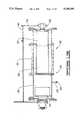
- FIG. 6is an elevational view of one end of the apparatus shown in FIG. 1.
- FIG. 7is an elevational view of the opposite end of the apparatus shown in FIG. 1.
- FIG. 8is a section taken along lines 8--8 of FIG. 5.
- FIG. 9is a plan view of a leg of the apparatus shown in FIG. 1.
- FIG. 10is an enlarged perspective of a portion of a leg of the apparatus shown in FIG. 1 with parts removed for clarity.
- FIG. 11is an enlarged sectional view taken along lines 11--11 of FIG. 5 with parts removed for clarity.
- FIG. 12is an enlarged schematic plan view of the cutter drive train of the apparatus of FIG. 1.
- FIG. 13is an enlarged sectional view taken along lines 13--13 of FIG. 5 with parts removed for clarity.
- FIG. 14is an enlarged elevation of the operator's control console for the apparatus shown in FIG. 1.
- FIG. 15is an enlarged view of the operator's controls for the apparatus shown in FIG. 1.
- FIG. 16is a schematic of the lift, steering, and cutter door system for the apparatus of FIG. 1.
- FIG. 17is a schematic diagram of the drive, brake, and speed select systems for the apparatus of FIG. 1.
- FIG. 18is an enlarged view of cutter door gages which may be used with the apparatus of FIG. 1.
- reference character 20generally designates an apparatus for preparing a surface constructed in accordance to this invention.
- the apparatus 20comprises a generally rectangular frame 22 with pneumatic tires 24, 26, 28 and 30 secured thereto for transporting the frame 22. Also secured to the frame 22 is a cutter 32 (FIGS. 3 and 4) for pulverizing a surface.
- "Surface" as used in the specification and in the claimsencompasses roads, parking lots, highway shoulders, fields and the like.
- the end 34 of the frame 22will be called the A end
- the end 36will be called the B end (FIGS. 3-5 and 7)
- the side 38will be called the absolute right side (FIGS. 4-7)
- the side 40will be called the absolute left side
- the side 42will be called the upper side (FIGS. 5-7).
- the upper side 42 of the frame 22has an operators platform 44. Pivotally secured to the operators platform 44 is a control console 46 which will be described in detail below.
- a ladder 48may extend down the absolute left side 40 of the frame 22 to facilitate access to the operators platform 44.
- a cutter housing 52Secured generally under the center of gravity 50 (see FIGS. 3 and 4) of the frame 22 is a cutter housing 52 which will be described in detail below.
- the frame 22is supported by legs 54, and 56 on the A end and legs 58 and 60 on the B end.
- Legs 56 and 58are identical, and legs 54 and 60 are the mirror image of legs 56 and 58. Since each leg is the same, only leg 54 will be described.
- the leg 54has arms, such as arms 64 and 66, wherein one end of each arm is pivotally secured to the frame 22.
- the other end of each armis pivotally secured to an axle housing 68.
- a lift cylinder 70Ais connected between axle housing 68 and the frame 22.
- the lift cylinder 70Ais adapted for raising and lowering the frame 22 relative to the leg 54.
- a steerinq sensor 72Secured on top of the axle housing 68 is a steerinq sensor 72 which will be discussed in detail below.
- rotatably attached to the axle housing 68is one end of an inverted L-shaped wheel yolk 74.
- a hub 76Secured to the opposite end of the wheel yolk 74 is a hub 76 containing a integral drive unit 78A (FIG. 1).
- the integral drive unit 78Ahas a hydraulic motor and a planetary reducer (not shown) and is adapted for turning the wheel 80 and pneumatic tire 30 which is mounted on the wheel 80.
- FIGS. 9 and 10show a steering cylinder 82A, one end of which is pivotally secured to yolk 74, such that when the steering cylinder 82A is extended or retracted, the yolk 74 pivots with respect to the axle housing 68, thus, steering the wheel 80.
- Shields 84 and 86are secured over part of the leg 54 to prevent an individual from inadvertently becoming entangled in the moving parts and to support white lights 88, red lights 90 and amber lights 92.
- Lights 88, 90 and 92are mounted in shield 86 to provide working and warning illumination. The operation of lights 88, 90 and 92 will be discussed in detail below.
- elevation sensors 94, 96 and 98are provided to determine the elevation of the frame 22 relative to each leg 54, 56, 58 or 60.
- An elevation sensoris not required on leg 58 because it's elevation is electronically determined from the elevation of legs 54, 56, and 60. This technique is described in detail in U.S. Pat. No. 3,637,026.
- the cutter housing 52has a generally semicircular top 100 and flat ends 102 and 104.
- An "A" door 106 and a “B” door 108are pivotally secured to the semicircular top 100.
- Secured to the lower side of each door 106 and 108is a flexible strip 110.
- Secured to the lower end of each flexible strip 110are a pair of steel plates 112 and 114.
- Each door, 106 and 108has a cylinder, 116 or 118 respectively, secured between it and the semicircular top 100.
- Each cylinder 116 and 118is adapted to raise and lower a door.
- Breaker bars 119(FIG. 11) may be secured to the semicircular top to aid in pulverizing material removed by the cutter 32.
- the cutter 32is rotatably secured within the cutter housing 52 by bearing 120 and planetary reducer 122.
- the cutter 32is made up of sections.
- the section 124comprises a first drum 126 and a second drum 128.
- the first drum 126has a larger diameter than the second drum 128 and also has a plurality of tooth brackets 130 (only one being shown) secured about the perimeter thereof.
- the first drum 126 sectionis preferably 48 inches long to correspond with the width of the inside shoulder of an interstate highway.
- the second drum 128works as an axle extending from the first drum 126 to bearing 120.
- a pair of clamshell sections 132may be secured over the second drum 128.
- the clamshell sections 132have tooth brackets (not shown) similar to those on the first drum 126, and serve to increase the working width of the cutter 32.
- a drive sheave 136is mounted on the input to the planetary reducer 122.
- a power band 138encircles the drive sheave 136 and a drive sheave 140.
- Drive sheave 140is driven by an internal combustion engine 142 via drive shaft 144, cutter transmission 146, drive shaft 150, drive sheave 164, power band 152, drive sheave 166 and clutch 154.
- the cutter transmission 146allows the operator to select the cutter speed that best fits the users requirement for optimum results.
- Levers (not shown) extending from the cutter transmission 146are accessible through an access door 148 (FIG. 1) on the operators platform 44. By manipulating the levers the operator may select different gear ratios causing the drive shaft 144 to rotate at different speeds, and thus, varying the rotational speed of the cutter 32.
- an additional drum section 158may be added to the end of the clamshell sections 132 to further increase the working width of the cutter 32.
- an extended housing section 160must be used to move the flat end 102 (FIGS. 12 and 13) outwardly.
- tooth brackets 130 and cutting teeth 162(FIG. 8) are not required, because suitable devices are disclosed in detail in U.S. Pat. Nos. 4,139,318 and 4,335,921 each of which are assigned to CMI Corporation, Oklahoma City, Okla., and which are expressly incorporated herein.
- a control console 46is located on the operators platform 44.
- the control console 46contains an operator's seat 168, and controls to operate and monitor the apparatus' systems.
- the control consoleis mounted on a swivel pedestal 170 which allows the console to rotate 180° to face the A end 34, the B end 36 or any position therebetween.
- the controlsmay be grouped into three groups, computer controls 172, manual operating controls 174, and additional system controls 176.
- the computer controls 172are located on the micro-controller 178.
- the majority of the manual operating controlsare located on a control panel 186, but a few are located on the control console 46 adjacent to the control panel 186.
- the additional systems controlsare located in the auxiliary panel 180.
- the additional systemsmay include systems such as an asphaltic emulsion system or a water system.
- a vandal cover 182(FIG. 14) is pivotally mounted so as to protect all three groups of controls from weather or tampering.
- control console 46houses steering wheel 184, light selector switch 190, flasher switch 192, ignition switch 194, horn switch 196, emergency steer switch 198, speed range switch 200, engine start switch 202, engine throttle switch 204, travel control lever 206, cutter door switches 208 and 210, manual elevation switches 212, 214, 216 and 218, travel direction switch 220, cutter engage switch 222, positrack switch 224 and parking brake switch 226.
- the ignition switch 194, the flasher switch 192, the engine start switch 202, the engine throttle switch 204 and the horn switch 196are common in the art and need not be described herein. The remaining switches will be described individually in detail below.
- Travel direction switch 220(hereinafter A/B switch) designates which end, the A end 34 or the B end 36, is the front end of the apparatus 20. As will be discussed below, the function of several of the manual controls is changed by moving the travel direction switch 220 from the "A" position 228 to the "B" position 230.
- the speed range selector switch 200controls the speed select valve 232 and also determines if secondary pump 234 will be brought on line to work in conjunction with primary pump 236.
- the speed range selector switch 200is a three position switch having low, medium and high positions (not shown). When the speed range selector switch 200 is in the low position, only primary pump 236 is on line and the speed select valve 232 is set to deliver hydraulic pressure from hydraulic line 238 to line 240 and on to integral drive units 78A, 78B, 78C and 78D. In this configuration, the integral drive units are high displacement. This should give the apparatus speeds up to about 150 F.P.M.
- the travel control lever 206controls the direction and speed of travel of the apparatus 20.
- the function of the travel control lever 206is dependant upon the position of the A/B switch 220 and the position of the speed range selector switch 200.
- the speed range selector switch 200determines whether only pump 236 is on line or whether both pumps 234 and 236 are on line.
- pumps 234 and 236are variable displacement pumps.
- the travel control lever 206when the travel control lever 206 is moved, it generates a signal which is sent to the pumps and controls the amount of fluid the pumps put out. The further the travel control lever 206 is moved from the center or neutral position, the more fluid is moved by the pumps.
- the fluidis directed out through either line 250 or line 252 depending on the position of the A/B switch 220. For example, if the operator has chosen the A position 228 on the A/B switch and pushes the travel control lever 206 to the forward position, fluid from the pumps, 234 and/or 236 flows through line 250 to the hydraulic motors 78A, 78B, 78C and 78D causing the apparatus 20 to move in the "A" direction. Fluid exiting the pumps travels via lines 256, 258, 260 and 262 back to the pumps. If the operator pulls the travel control lever 206 to the reverse position the circuit is revered and the apparatus 20 moves in the "B" direction.
- the cutter door switches 208 and 210are also dependent upon the position of the A/B switch 220.
- Cutter door switch 208controls valve 268 when the A/B switch is in the "A” position and valve 270 when the A/B switch 220 is in the "B” position.
- the cutter door switch 210controls valve 270 when the A/B switch is in the "A” position and valve 268 when the A/B switch is in the B position.
- valve 268will open and allow fluid from the line 272 to enter cylinder 116 through line 274, thereby opening the "A" door 106.
- each gagehas a cable 296 which runs from a cutter door to a slidingly secured pointer 298. As a door opens, the cable pushes the pointer up, thereby indicating the position of the door.
- the manual elevation switches 212, 214, 216 and 218control the lift cylinders 70A, 70B, 70C and 70D if the computer controls 172 are set for manual control.
- the manual elevation switches 212, and 218control lift valves 278 and 280 respectively.
- Manual elevation switch 214 or 216controls valve 282. That is, cylinders 70A and 70C are tied together hydraulically so that either manual elevation switch 214 or 216 controls both cylinders 70A and 70C.
- the manual elevation switchesmay be used to steer the apparatus 20. When the emergency steer switch 198 is "ON", switches 212, 214, 216 and 218 no longer control lift valves 278, 280 or 282, but instead control steering valves 284, 286, 288, and 290 respectively.
- the light selector switch 190has three positions; off, work and run (not shown). In the work position all white lights 88 at both the front and rear of the apparatus will be active. If the flasher switch 192 is also in the "ON" position then in addition to the white lights 88, the red lights 90 and amber lights 92 will be active dependant upon the position of the A/B switch 220. That is if the A/B switch 220 is in the "A" position, then the red lights on the "B” end will flash and the amber lights 92 on the "A" end will flash.
- travel lightswill be activated, dependent upon the position of the A/B switch 220. For example, when the A/B switch 220 is in the "A" position 228 the white lights 88 on the A end 34 will be energized and the red lights 90 on the B end 36 will be energized. In addition, if the flasher switch is in the "ON” position then the amber lights 92 on the "A" end will flash and the red lights 90 on the "B” end will flash. If the A/B switch 220 is in the "B" position 230 just the opposite will occur.
- the steering wheel 184controls the steering of the apparatus 20. Unless the emergency steer switch 196 is set to "ON", the steering wheel 184, in conjunction with the micro-controller 178, controls the steering cylinders 82A, 82B, 82C and 82D. In operation, a sensor (not shown) generates a signal in response to movement of the steering wheel 184. The micro-controller 178 then generates signals which control steering valves 284, 286, 288 and 290. The signals transmitted by the micro-controller 178 are dependant upon what type of steering, 2 wheel, 4 wheel coordinated, or 4 wheel crab, has been selected on the micro-controller 178 and which position, 228 or 230, has been selected on the A/B switch 220.
- Two types of 2 wheel steeringmay be selected on the microcontroller 178, leading wheel steering or trailing wheel steering.
- the micro-controller 178determines which end, the A end 34 or the B end 36 (FIG. 5) is the leading end by reading the position of the A/B switch 220.
- cylinders 82A and 82B, or cylinders 82C and 82Dare operated in response to movement of the steering wheel 184.
- 4 wheel coordinated or 4 wheel crab steeringmay be selected. If this type of steering is selected, the cylinders 82A, 82B, 82C and 82D are operated in response to movement of the steering wheel 184. For example, if 4 wheel coordinated steering is selected and the A/B switch is in the "A" position 228, the rotation of the steering wheel 184 in a clockwise direction would cause the wheels on the A end 34 to rotate clockwise, as viewed from above, and the wheels on the B end 36 to rotate counterclockwise, as viewed from above.
- brake valve 292(FIG. 17) is open directing pressure from line 238 through line 294 to hydraulic motors 78A, 78B, 78C and 78D locking the motors in a fixed position.
- the cutter engage/disengage switch 222engages the cutter 32 by engaging a clutch 154 (FIG. 12). This type of switch is common in the art and need not be described further here.
- the positrack switch 224controls valve 310 thereby selecting positrack or normal drive.
- control valve 310directs pressure to bypass valve 308 which interrupts fluid flow through lines between line 312 and lines 314A, 314B, 314C and 314D. With the bypass valve 308 closed, the fluid must pass through the fluid equalizing valve 306. Thus, the quantity of fluid reaching each hydraulic drive assembly 78A, 78B, 78C and 78D is equal.
- the apparatushas an onboard microcontroller 178 located in the control console 46.
- the microcontrollerincludes feedback monitoring of all critical machine components and functions.
- a suitable micro-controlleris a System 90 micro-controller which may be purchased from Sauer-Sundstrand, Minneapolis, Minn. Some of the functions of the microcontroller 178 have been mentioned above, others of importance are: automatically control elevation and slope; monitor apparatus speed; reduce apparatus speed if cutter power plant revolutions per minute drops below a predetermined value; monitor and warn of problems with power plant, electrical, or hydraulic systems. Programming of the micro-controller for performing the various functions referred to is within the skill of the art.
- a spray apparatusmay be secured to cutter housing 52 for adding liquid to the road bed while it is being pulverized.
- Spray nozzles 316may penetrate the housing 52 for dispersing the liquid additives.
- the spray nozzles 316may be supplied by lines 318 which run from an onboard tank 320 or to a tank truck (not shown) positioned to be pushed by the apparatus in a manner as is described in my co-pending application entitled "SYSTEM FOR RECLAIMING AND RELAYING PAVEMENT IN PLACE". In an operating condition, spray nozzles 316 are pivoted to extend through openings in hood 100 and the breaker bar 119 is removed.
- the controls for the spray systemmay be mounted in the auxiliary panel 180 on the control console 46 (FIGS. 14 and 15).
Landscapes
- Engineering & Computer Science (AREA)
- Mechanical Engineering (AREA)
- Architecture (AREA)
- Civil Engineering (AREA)
- Structural Engineering (AREA)
- Chemical & Material Sciences (AREA)
- Combustion & Propulsion (AREA)
- Transportation (AREA)
- Mining & Mineral Resources (AREA)
- Road Repair (AREA)
Abstract
Description
Claims (18)
Priority Applications (1)
| Application Number | Priority Date | Filing Date | Title |
|---|---|---|---|
| US07/667,914US5190398A (en) | 1991-03-12 | 1991-03-12 | Apparatus for preparing a road bed |
Applications Claiming Priority (1)
| Application Number | Priority Date | Filing Date | Title |
|---|---|---|---|
| US07/667,914US5190398A (en) | 1991-03-12 | 1991-03-12 | Apparatus for preparing a road bed |
Publications (1)
| Publication Number | Publication Date |
|---|---|
| US5190398Atrue US5190398A (en) | 1993-03-02 |
Family
ID=24680185
Family Applications (1)
| Application Number | Title | Priority Date | Filing Date |
|---|---|---|---|
| US07/667,914Expired - LifetimeUS5190398A (en) | 1991-03-12 | 1991-03-12 | Apparatus for preparing a road bed |
Country Status (1)
| Country | Link |
|---|---|
| US (1) | US5190398A (en) |
Cited By (43)
| Publication number | Priority date | Publication date | Assignee | Title |
|---|---|---|---|---|
| US5354147A (en)* | 1993-07-08 | 1994-10-11 | Swisher Jr George W | Pulverizing machine having a cutter assembly towed in both forward and reverse directions |
| US5383743A (en)* | 1993-09-07 | 1995-01-24 | Swisher, Jr.; George W. | Vehicle having a drive train with two shock-absorbing couplings |
| WO1996024725A1 (en)* | 1995-02-12 | 1996-08-15 | Wirtgen Gmbh | Roadworking machine |
| US5639181A (en)* | 1993-06-15 | 1997-06-17 | Swisher, Jr.; George W. | Construction machine having compression-memory solid rubber tires |
| US5718535A (en)* | 1995-03-31 | 1998-02-17 | Svedala Strassenfertiger Gmbh, Niederlassung Lingen/Ems | Finisher for road surfaces with a tire drive |
| US6050743A (en)* | 1995-11-28 | 2000-04-18 | Medinger; Jean Claude | Spreader for treating soil |
| US6149342A (en)* | 1999-03-25 | 2000-11-21 | Cmi Corporation | Anti-bridging mechanism |
| US6176551B1 (en) | 1997-09-30 | 2001-01-23 | James H. Page | Surface preparation apparatus and method of using the same |
| US6213560B1 (en) | 1999-03-19 | 2001-04-10 | Caterpillar Paving Products Inc. | Variable width milling drum |
| US6398454B1 (en)* | 2000-01-24 | 2002-06-04 | Romolo Bitelli | Vibratory finishing machine for road asphalting |
| EP1197602A3 (en)* | 2000-10-12 | 2002-12-18 | STEINBRECHER, Michael | Multi-purpose cutter-breaker apparatus |
| US6540305B2 (en)* | 2000-03-20 | 2003-04-01 | Edward W. Phillips | Electric floor covering removal apparatus |
| EP1039037A3 (en)* | 1999-03-23 | 2003-04-02 | BITELLI S.p.A. | Heavy vehicle for breaking up ground with retracting and steering rear wheels |
| US20040135421A1 (en)* | 2001-04-27 | 2004-07-15 | Dubay Gregory Henry | Milling machine with re-entering back wheels |
| DE10347874A1 (en)* | 2003-10-10 | 2005-05-12 | Wirtgen Gmbh | Rear loader road milling machine with height-adjustable sealing device |
| US20060216113A1 (en)* | 2005-03-24 | 2006-09-28 | Richard Silbernagel | Road construction apparatus with pivotally connected trimmer |
| US7160056B1 (en) | 2005-03-11 | 2007-01-09 | Roadtee, Inc. | Material transfer vehicle for use in asphalt paving |
| US20070137903A1 (en)* | 2003-12-11 | 2007-06-21 | E.Falck Schmidt A/S | Vehicle with an under-carriage provided with crawler belts |
| US20080008527A1 (en)* | 2006-07-06 | 2008-01-10 | Diamond Surface, Inc. | Close proximity grinder |
| US20080246328A1 (en)* | 2003-12-04 | 2008-10-09 | Thomas Mannebach | Automotive Machine for Producing Carriageways |
| US20080258535A1 (en)* | 2007-04-19 | 2008-10-23 | Wirtgen Gmbh | Automotive construction machine |
| DE202008016935U1 (en) | 2008-12-23 | 2010-06-10 | Wirtgen Gmbh | Construction machine, in particular stabilizer or recycler |
| US20100215449A1 (en)* | 2009-02-05 | 2010-08-26 | Kern Robert L | Drilling Apparatus |
| USD626573S1 (en)* | 2007-08-14 | 2010-11-02 | Wirtgen Gmbh | Road milling machine |
| WO2010145645A1 (en)* | 2009-06-18 | 2010-12-23 | Michael Steinbrecher | Drive system for the milling drum of a mobile milling machine |
| USD635159S1 (en)* | 2010-03-19 | 2011-03-29 | Wirtgen Gmbh | Body panels for a construction machine |
| USD642599S1 (en) | 2010-10-12 | 2011-08-02 | Wirtgen Gmbh | Body panels for a construction machine |
| CN102400438A (en)* | 2011-11-24 | 2012-04-04 | 陕西长大实业有限公司 | Crushing, milling and planning roller |
| USD660882S1 (en)* | 2011-05-30 | 2012-05-29 | Wirtgen Gmbh | Body panels for a road construction machine |
| US20130134765A1 (en)* | 2011-11-30 | 2013-05-30 | Asphalt Zipper, Inc. | Steerable system for asphalt milling attachment |
| US8794869B2 (en) | 2012-04-30 | 2014-08-05 | Caterpillar Paving Products Inc. | Rotary mixer and method for controlling material gradation thereof |
| CN104099858A (en)* | 2013-04-09 | 2014-10-15 | 宝马格有限公司 | Ground milling machine with optimized-field-of-view tail, especially road cold milling machine |
| USD755859S1 (en)* | 2014-08-12 | 2016-05-10 | Bomag Gmbh | Milling machine |
| EP3376067A1 (en) | 2017-03-15 | 2018-09-19 | Wirtgen GmbH | Soil working machine with gear speed change between drive motor and rotatable working device |
| EP3498918A1 (en)* | 2017-12-18 | 2019-06-19 | Wirtgen GmbH | Soil-working machine with control panel with improved protection against vandalism |
| US10378350B2 (en) | 2016-08-30 | 2019-08-13 | Wirtgen Gmbh | Milling machine and process for the operation of a milling machine |
| US10465347B2 (en) | 2016-08-29 | 2019-11-05 | Wirtgen Gmbh | Method for working ground pavements, as well as self-propelled construction machine |
| US10625629B2 (en) | 2013-12-11 | 2020-04-21 | Prinoth Ltd. | Snow groomer or other tracked vehicle and systems therefor |
| US20210198853A1 (en)* | 2019-12-30 | 2021-07-01 | Wirtgen Gmbh | Removing earth working method with a removing tool offset obliquely with respect to the propulsion direction, and earth working machine embodied to execute the method |
| US11136732B2 (en) | 2020-01-28 | 2021-10-05 | Caterpillar Paving Products Inc. | Milling machine having pivot arms offset from engine output shaft |
| US11208772B2 (en) | 2016-01-21 | 2021-12-28 | Surface Preparation Technologies, Llc | Reduced volume sonic noise alert pattern grinder and method |
| US20230203764A1 (en)* | 2021-12-23 | 2023-06-29 | Wirtgen Gmbh | Construction Machine |
| EP4442905A1 (en)* | 2023-03-28 | 2024-10-09 | Wirtgen GmbH | Self-propelled construction machine for working ground surfaces |
Citations (13)
| Publication number | Priority date | Publication date | Assignee | Title |
|---|---|---|---|---|
| US3568778A (en)* | 1969-01-23 | 1971-03-09 | Cmi Corp | Motor grader apparatus |
| US3612611A (en)* | 1970-04-16 | 1971-10-12 | Concut Inc | Rotary cutter assembly for a pavement grooving machine |
| US3637026A (en)* | 1969-10-06 | 1972-01-25 | Cmi Corp | Cross slope control of mobile machinery |
| US3765724A (en)* | 1971-03-01 | 1973-10-16 | C Hatcher | Pavement cutting machine with tractor-trailer assembly |
| US3779606A (en)* | 1971-03-01 | 1973-12-18 | C Hatcher | Pavement cutting machine with improved liquid coolant supply |
| US3779608A (en)* | 1971-03-01 | 1973-12-18 | C Hatcher | Pavement cutting machine with selected drive system |
| US3868146A (en)* | 1972-06-09 | 1975-02-25 | Super Cut | Pavement grooving machine |
| US3888542A (en)* | 1972-12-22 | 1975-06-10 | Non Impact Surfaces Limited | Road planing machines |
| US3895843A (en)* | 1973-10-23 | 1975-07-22 | British Jeffrey Diamond Limite | Road planing machine |
| US4139318A (en)* | 1976-03-31 | 1979-02-13 | Cmi Corporation | Method and apparatus for planing a paved roadway |
| US4335921A (en)* | 1977-06-06 | 1982-06-22 | Cmi Corporation | Cutting head for a paved roadway resurfacing apparatus |
| US4968099A (en)* | 1989-02-14 | 1990-11-06 | Target Products Inc. | Fluid control system for roadway grooving apparatus |
| US4986604A (en)* | 1989-02-07 | 1991-01-22 | Target Products Inc. | Roadway grooving apparatus |
- 1991
- 1991-03-12USUS07/667,914patent/US5190398A/ennot_activeExpired - Lifetime
Patent Citations (13)
| Publication number | Priority date | Publication date | Assignee | Title |
|---|---|---|---|---|
| US3568778A (en)* | 1969-01-23 | 1971-03-09 | Cmi Corp | Motor grader apparatus |
| US3637026A (en)* | 1969-10-06 | 1972-01-25 | Cmi Corp | Cross slope control of mobile machinery |
| US3612611A (en)* | 1970-04-16 | 1971-10-12 | Concut Inc | Rotary cutter assembly for a pavement grooving machine |
| US3765724A (en)* | 1971-03-01 | 1973-10-16 | C Hatcher | Pavement cutting machine with tractor-trailer assembly |
| US3779606A (en)* | 1971-03-01 | 1973-12-18 | C Hatcher | Pavement cutting machine with improved liquid coolant supply |
| US3779608A (en)* | 1971-03-01 | 1973-12-18 | C Hatcher | Pavement cutting machine with selected drive system |
| US3868146A (en)* | 1972-06-09 | 1975-02-25 | Super Cut | Pavement grooving machine |
| US3888542A (en)* | 1972-12-22 | 1975-06-10 | Non Impact Surfaces Limited | Road planing machines |
| US3895843A (en)* | 1973-10-23 | 1975-07-22 | British Jeffrey Diamond Limite | Road planing machine |
| US4139318A (en)* | 1976-03-31 | 1979-02-13 | Cmi Corporation | Method and apparatus for planing a paved roadway |
| US4335921A (en)* | 1977-06-06 | 1982-06-22 | Cmi Corporation | Cutting head for a paved roadway resurfacing apparatus |
| US4986604A (en)* | 1989-02-07 | 1991-01-22 | Target Products Inc. | Roadway grooving apparatus |
| US4968099A (en)* | 1989-02-14 | 1990-11-06 | Target Products Inc. | Fluid control system for roadway grooving apparatus |
Non-Patent Citations (9)
| Title |
|---|
| Bomag AMCA International, BOMAG MPH100 Recycler (no date).* |
| Caterpillar, CAT RR 250 Road Reclaimer (1987).* |
| Caterpillar, CAT RR-250 Road Reclaimer (1987). |
| Caterpillar, product training bulletin (1986) RR 250.* |
| Caterpillar, product training bulletin (1986) RR-250. |
| Pettibone, Model P 500 SP (Hammermill) Pulverizer (no date).* |
| Pettibone, Model P-500-SP (Hammermill) Pulverizer (no date). |
| Rexworks, Inc., Pulvi Master Reclaimer & Stabilizer (no date) (1 page).* |
| Rexworks, Inc., Pulvi-Master Reclaimer & Stabilizer (no date) (1 page). |
Cited By (92)
| Publication number | Priority date | Publication date | Assignee | Title |
|---|---|---|---|---|
| US5639181A (en)* | 1993-06-15 | 1997-06-17 | Swisher, Jr.; George W. | Construction machine having compression-memory solid rubber tires |
| US5354147A (en)* | 1993-07-08 | 1994-10-11 | Swisher Jr George W | Pulverizing machine having a cutter assembly towed in both forward and reverse directions |
| US5383743A (en)* | 1993-09-07 | 1995-01-24 | Swisher, Jr.; George W. | Vehicle having a drive train with two shock-absorbing couplings |
| WO1996024725A1 (en)* | 1995-02-12 | 1996-08-15 | Wirtgen Gmbh | Roadworking machine |
| US5893677A (en)* | 1995-02-12 | 1999-04-13 | Wirtgen Gmbh | Roadworking machine |
| US5718535A (en)* | 1995-03-31 | 1998-02-17 | Svedala Strassenfertiger Gmbh, Niederlassung Lingen/Ems | Finisher for road surfaces with a tire drive |
| US6050743A (en)* | 1995-11-28 | 2000-04-18 | Medinger; Jean Claude | Spreader for treating soil |
| US6176551B1 (en) | 1997-09-30 | 2001-01-23 | James H. Page | Surface preparation apparatus and method of using the same |
| US6213560B1 (en) | 1999-03-19 | 2001-04-10 | Caterpillar Paving Products Inc. | Variable width milling drum |
| EP1039037A3 (en)* | 1999-03-23 | 2003-04-02 | BITELLI S.p.A. | Heavy vehicle for breaking up ground with retracting and steering rear wheels |
| EP2327836A1 (en)* | 1999-03-23 | 2011-06-01 | Caterpillar Paving Products Inc. | Heavy vehicle for breaking up ground with retracting and steering rear wheels |
| EP1714854A3 (en)* | 1999-03-23 | 2008-01-23 | Caterpillar Paving Products Inc. | Heavy vehicle for breaking up ground with retracting and steering rear wheels |
| EP1039036A3 (en)* | 1999-03-25 | 2002-01-02 | CMI Corporation | Anti-bridging mechanism |
| US6149342A (en)* | 1999-03-25 | 2000-11-21 | Cmi Corporation | Anti-bridging mechanism |
| US6398454B1 (en)* | 2000-01-24 | 2002-06-04 | Romolo Bitelli | Vibratory finishing machine for road asphalting |
| US6540305B2 (en)* | 2000-03-20 | 2003-04-01 | Edward W. Phillips | Electric floor covering removal apparatus |
| EP1197602A3 (en)* | 2000-10-12 | 2002-12-18 | STEINBRECHER, Michael | Multi-purpose cutter-breaker apparatus |
| US20040135421A1 (en)* | 2001-04-27 | 2004-07-15 | Dubay Gregory Henry | Milling machine with re-entering back wheels |
| US7140693B2 (en) | 2001-04-27 | 2006-11-28 | Bitelli Spa | Milling machine with re-entering back wheels |
| DE10347874A1 (en)* | 2003-10-10 | 2005-05-12 | Wirtgen Gmbh | Rear loader road milling machine with height-adjustable sealing device |
| US20050123350A1 (en)* | 2003-10-10 | 2005-06-09 | Herbert Ley | Rear loader road milling machine with height-adjustable sealing device |
| US7370916B2 (en)* | 2003-10-10 | 2008-05-13 | Wirtgen Gmbh | Rear loader road milling machine with height-adjustable sealing device |
| CN100357522C (en)* | 2003-10-10 | 2007-12-26 | 维特根有限公司 | Rear loading road milling machine with height adjustable sealing device |
| US20080246328A1 (en)* | 2003-12-04 | 2008-10-09 | Thomas Mannebach | Automotive Machine for Producing Carriageways |
| US7918512B2 (en)* | 2003-12-04 | 2011-04-05 | Wirtgen Gmbh | Automotive machine for producing carriageways |
| US8840191B2 (en) | 2003-12-04 | 2014-09-23 | Wirtgen Gmbh | Automotive machine for producing carriageways |
| US9068304B2 (en) | 2003-12-04 | 2015-06-30 | Wirtgen Gmbh | Automotive machine for producing carriageways |
| US8075063B2 (en)* | 2003-12-04 | 2011-12-13 | Wirtgen Gmbh | Automotive machine for producing carriageways |
| US20110140505A1 (en)* | 2003-12-04 | 2011-06-16 | Wirtgen Gmbh | Automotive Machine For Producing Carriageways |
| US20070137903A1 (en)* | 2003-12-11 | 2007-06-21 | E.Falck Schmidt A/S | Vehicle with an under-carriage provided with crawler belts |
| US7160056B1 (en) | 2005-03-11 | 2007-01-09 | Roadtee, Inc. | Material transfer vehicle for use in asphalt paving |
| US20060216113A1 (en)* | 2005-03-24 | 2006-09-28 | Richard Silbernagel | Road construction apparatus with pivotally connected trimmer |
| US7837276B2 (en)* | 2006-07-06 | 2010-11-23 | Diamond Surface, Inc. | Close proximity grinder |
| US20080008527A1 (en)* | 2006-07-06 | 2008-01-10 | Diamond Surface, Inc. | Close proximity grinder |
| US20110062767A1 (en)* | 2006-07-06 | 2011-03-17 | Diamond Surface, Inc. | Close proximity grinder |
| US8025342B2 (en) | 2006-07-06 | 2011-09-27 | Diamond Surface, Inc. | Close proximity grinder |
| US9181664B2 (en) | 2007-04-19 | 2015-11-10 | Wirtgen Gmbh | Automotive construction machine |
| AU2008201640B2 (en)* | 2007-04-19 | 2011-01-27 | Wirtgen Gmbh | Automotive construction machine |
| US8590983B2 (en) | 2007-04-19 | 2013-11-26 | Wirtgen Gmbh | Automotive construction machine |
| US20080258535A1 (en)* | 2007-04-19 | 2008-10-23 | Wirtgen Gmbh | Automotive construction machine |
| US10100471B2 (en) | 2007-04-19 | 2018-10-16 | Wirtgen Gmbh | Automotive construction machine |
| USD626573S1 (en)* | 2007-08-14 | 2010-11-02 | Wirtgen Gmbh | Road milling machine |
| DE202008016935U1 (en) | 2008-12-23 | 2010-06-10 | Wirtgen Gmbh | Construction machine, in particular stabilizer or recycler |
| US20170165763A1 (en)* | 2009-02-05 | 2017-06-15 | Minnich Manufacturing Company, Inc. | Gang drill apparatus |
| US9527140B2 (en)* | 2009-02-05 | 2016-12-27 | Minnich Manufacturing Company, Inc. | Drilling apparatus |
| US20100215449A1 (en)* | 2009-02-05 | 2010-08-26 | Kern Robert L | Drilling Apparatus |
| WO2010145645A1 (en)* | 2009-06-18 | 2010-12-23 | Michael Steinbrecher | Drive system for the milling drum of a mobile milling machine |
| USD635158S1 (en)* | 2010-03-16 | 2011-03-29 | Wirtgen Gmbh | Body panels for a construction machine |
| USD635593S1 (en)* | 2010-03-19 | 2011-04-05 | Wirtgen Gmbh | Body panels for a construction machine |
| USD635160S1 (en)* | 2010-03-19 | 2011-03-29 | Wirtgen Gmbh | Body panels for a construction machine |
| USD635159S1 (en)* | 2010-03-19 | 2011-03-29 | Wirtgen Gmbh | Body panels for a construction machine |
| USD643860S1 (en) | 2010-10-12 | 2011-08-23 | Wirtgen Gmbh | Body panels for a construction machine |
| USD642599S1 (en) | 2010-10-12 | 2011-08-02 | Wirtgen Gmbh | Body panels for a construction machine |
| USD660882S1 (en)* | 2011-05-30 | 2012-05-29 | Wirtgen Gmbh | Body panels for a road construction machine |
| USD661321S1 (en)* | 2011-05-30 | 2012-06-05 | Wirtgen Gmbh | Body panels and cab assembly for a road construction machine |
| USD660883S1 (en)* | 2011-05-30 | 2012-05-29 | Wirtgen Gmbh | Body panels for a road construction machine |
| CN102400438A (en)* | 2011-11-24 | 2012-04-04 | 陕西长大实业有限公司 | Crushing, milling and planning roller |
| CN102400438B (en)* | 2011-11-24 | 2016-05-25 | 陕西长大实业有限公司 | Broken milling cylinder |
| US20130134765A1 (en)* | 2011-11-30 | 2013-05-30 | Asphalt Zipper, Inc. | Steerable system for asphalt milling attachment |
| US10086867B2 (en)* | 2011-11-30 | 2018-10-02 | Asphalt Zipper, Inc. | Steerable system for asphalt milling attachment |
| US8851792B1 (en) | 2012-04-30 | 2014-10-07 | Caterpillar Paving Products Inc. | Rotary mixer and method for controlling material gradation thereof |
| US8794869B2 (en) | 2012-04-30 | 2014-08-05 | Caterpillar Paving Products Inc. | Rotary mixer and method for controlling material gradation thereof |
| CN104099858B (en)* | 2013-04-09 | 2017-10-17 | 宝马格有限公司 | The ground milling machine of afterbody with field-of-view optimization |
| CN104099858A (en)* | 2013-04-09 | 2014-10-15 | 宝马格有限公司 | Ground milling machine with optimized-field-of-view tail, especially road cold milling machine |
| US11505906B2 (en) | 2013-12-11 | 2022-11-22 | Prinoth Ltd. | Snow groomer or other tracked vehicle and systems therefor |
| US10625629B2 (en) | 2013-12-11 | 2020-04-21 | Prinoth Ltd. | Snow groomer or other tracked vehicle and systems therefor |
| USD755859S1 (en)* | 2014-08-12 | 2016-05-10 | Bomag Gmbh | Milling machine |
| US11208772B2 (en) | 2016-01-21 | 2021-12-28 | Surface Preparation Technologies, Llc | Reduced volume sonic noise alert pattern grinder and method |
| US11492767B2 (en) | 2016-08-29 | 2022-11-08 | Wirtgen Gmbh | Method for working ground pavements, as well as self-propelled construction machine |
| US10465347B2 (en) | 2016-08-29 | 2019-11-05 | Wirtgen Gmbh | Method for working ground pavements, as well as self-propelled construction machine |
| US11203929B2 (en) | 2016-08-30 | 2021-12-21 | Wirtgen Gmbh | Milling machine and process for the operation of a milling machine |
| US12312955B2 (en) | 2016-08-30 | 2025-05-27 | Wirtgen Gmbh | Milling machine and process for the operation of a milling machine |
| US10378350B2 (en) | 2016-08-30 | 2019-08-13 | Wirtgen Gmbh | Milling machine and process for the operation of a milling machine |
| EP3376067A1 (en) | 2017-03-15 | 2018-09-19 | Wirtgen GmbH | Soil working machine with gear speed change between drive motor and rotatable working device |
| US11346443B2 (en) | 2017-03-15 | 2022-05-31 | Wirtgen Gmbh | Earth working machine having a shiftable transmission between a drive motor and a rotatable working apparatus |
| DE102017204336A1 (en) | 2017-03-15 | 2018-09-20 | Wirtgen Gmbh | Soil cultivation machine with manual transmission between drive motor and rotatable working device |
| US12253166B2 (en) | 2017-03-15 | 2025-03-18 | Wirtgen Gmbh | Earth working machine having a shiftable transmission between a drive motor and a rotatable working apparatus |
| EP3869067A1 (en) | 2017-03-15 | 2021-08-25 | Wirtgen GmbH | Soil processing machine with a gearbox with a two-part switching stage with only slightly different transmission ratios |
| US11859717B2 (en) | 2017-03-15 | 2024-01-02 | Wirtgen Gmbh | Earth working machine having a shiftable transmission between a drive motor and a rotatable working apparatus |
| US10718431B2 (en) | 2017-03-15 | 2020-07-21 | Wirtgen Gmbh | Earth working machine having a shiftable transmission between a drive motor and a rotatable working apparatus |
| EP3575633A1 (en) | 2017-03-15 | 2019-12-04 | Wirtgen GmbH | SOIL WORKING MACHINE WITH VARIABLE GEAR WITH A PLURALITY OF PTOýS BETWEEN DRIVE MOTOR AND ROTATABLE WORKING DEVICE |
| CN109930460A (en)* | 2017-12-18 | 2019-06-25 | 维特根有限公司 | Ground side machining apparatus with the station for including improved tamper protection |
| US10822754B2 (en) | 2017-12-18 | 2020-11-03 | Wirtgen Gmbh | Earth working machine having an operating console with improved vandalism protection |
| EP3498918A1 (en)* | 2017-12-18 | 2019-06-19 | Wirtgen GmbH | Soil-working machine with control panel with improved protection against vandalism |
| CN109930460B (en)* | 2017-12-18 | 2021-07-09 | 维特根有限公司 | Ground processing machine with work station including improved tamper protection |
| US11802384B2 (en)* | 2019-12-30 | 2023-10-31 | Wirtgen Gmbh | Removing earth working method with a removing tool offset obliquely with respect to the propulsion direction, and earth working machine embodied to execute the method |
| US12264443B2 (en) | 2019-12-30 | 2025-04-01 | Wirtgen Gmbh | Removing earth working method with a removing tool offset obliquely with respect to the propulsion direction, and earth working machine embodied to execute the method |
| US20210198853A1 (en)* | 2019-12-30 | 2021-07-01 | Wirtgen Gmbh | Removing earth working method with a removing tool offset obliquely with respect to the propulsion direction, and earth working machine embodied to execute the method |
| US11136732B2 (en) | 2020-01-28 | 2021-10-05 | Caterpillar Paving Products Inc. | Milling machine having pivot arms offset from engine output shaft |
| US20230203764A1 (en)* | 2021-12-23 | 2023-06-29 | Wirtgen Gmbh | Construction Machine |
| US12320080B2 (en)* | 2021-12-23 | 2025-06-03 | Wirtgen Gmbh | Construction machine |
| EP4442905A1 (en)* | 2023-03-28 | 2024-10-09 | Wirtgen GmbH | Self-propelled construction machine for working ground surfaces |
Similar Documents
| Publication | Publication Date | Title |
|---|---|---|
| US5190398A (en) | Apparatus for preparing a road bed | |
| US7942604B2 (en) | Propulsion and steering system for a road milling machine | |
| US7299610B2 (en) | Park/drive mechanical interlock system for zero turn radius mowers | |
| US6283220B1 (en) | Remote control vehicle | |
| US5711139A (en) | Self-leveling hillside mower with remote control | |
| US5636648A (en) | Mobile rotator jet sewer cleaner | |
| US3590948A (en) | Basket-leveling system for boom structures | |
| US2743567A (en) | Multiple unit contour mower | |
| US5042238A (en) | Riding lawn mower | |
| CA2181625C (en) | Steering control device for vehicle having continuously variable transmission | |
| US7493711B2 (en) | Ride-on snow blower | |
| US3824772A (en) | Turf maintenance machine | |
| US20010001187A1 (en) | Driving system for a working vehicle | |
| NO154457B (en) | HYDRAULIC MOTOR DRIVE, TILTED CLEANING VEHICLE. | |
| EA008383B1 (en) | Tractor with reversible operator position for operation and transport | |
| US5212896A (en) | Control system for a walk behind trencher machine | |
| US3969035A (en) | Slip from paving machine | |
| US3694033A (en) | Roadway paint stripe grooving machine | |
| US5651241A (en) | Walk-behind mower controls with dual function control bracket | |
| US3559385A (en) | Slopemower apparatus for highway and railroad rights-of-way | |
| US6176551B1 (en) | Surface preparation apparatus and method of using the same | |
| US2684695A (en) | Self-propelled portable power saw | |
| US2631737A (en) | Highway crane | |
| JP6667811B2 (en) | Moving trolley | |
| JP3960509B2 (en) | Traveling work machine |
Legal Events
| Date | Code | Title | Description |
|---|---|---|---|
| AS | Assignment | Owner name:CONGRESS FINANCIAL CORPORATION (SOUTHWEST) A COR Free format text:SECURITY INTEREST;ASSIGNOR:CMI CORPORATION A CORP. OF OKLAHOMA;REEL/FRAME:005984/0346 Effective date:19911205 Owner name:CONGRESS FINANCIAL CORPORATION (SOUTHWEST), TEXAS Free format text:SECURITY INTEREST;ASSIGNOR:CMI CORPORATION;REEL/FRAME:005984/0346 Effective date:19911205 | |
| STCF | Information on status: patent grant | Free format text:PATENTED CASE | |
| FPAY | Fee payment | Year of fee payment:4 | |
| FPAY | Fee payment | Year of fee payment:8 | |
| FPAY | Fee payment | Year of fee payment:12 | |
| REMI | Maintenance fee reminder mailed | ||
| SULP | Surcharge for late payment | Year of fee payment:11 | |
| AS | Assignment | Owner name:CREDIT SUISSE, AS COLLATERAL AGENT, NEW YORK Free format text:SECURITY AGREEMENT;ASSIGNORS:TEREX CORPORATION;AMIDA INDUSTRIES, INC.;A.S.V., INC.;AND OTHERS;REEL/FRAME:023107/0892 Effective date:20090714 Owner name:CREDIT SUISSE, AS COLLATERAL AGENT,NEW YORK Free format text:SECURITY AGREEMENT;ASSIGNORS:TEREX CORPORATION;AMIDA INDUSTRIES, INC.;A.S.V., INC.;AND OTHERS;REEL/FRAME:023107/0892 Effective date:20090714 | |
| AS | Assignment | Owner name:A.S.V., INC., MINNESOTA Free format text:RELEASE BY SECURED PARTY;ASSIGNOR:CREDIT SUISSE AG, CAYMAN ISLANDS BRANCH, AS COLLATERAL AGENT;REEL/FRAME:026955/0817 Effective date:20110811 Owner name:GENIE INDUSTRIES, INC., WASHINGTON Free format text:RELEASE BY SECURED PARTY;ASSIGNOR:CREDIT SUISSE AG, CAYMAN ISLANDS BRANCH, AS COLLATERAL AGENT;REEL/FRAME:026955/0817 Effective date:20110811 Owner name:CMI TEREX CORPORATION, OKLAHOMA Free format text:RELEASE BY SECURED PARTY;ASSIGNOR:CREDIT SUISSE AG, CAYMAN ISLANDS BRANCH, AS COLLATERAL AGENT;REEL/FRAME:026955/0817 Effective date:20110811 Owner name:TEREX CORPORATION, CONNECTICUT Free format text:RELEASE BY SECURED PARTY;ASSIGNOR:CREDIT SUISSE AG, CAYMAN ISLANDS BRANCH, AS COLLATERAL AGENT;REEL/FRAME:026955/0817 Effective date:20110811 Owner name:TEREX CRANES WILMINGTON, INC., CONNECTICUT Free format text:RELEASE BY SECURED PARTY;ASSIGNOR:CREDIT SUISSE AG, CAYMAN ISLANDS BRANCH, AS COLLATERAL AGENT;REEL/FRAME:026955/0817 Effective date:20110811 Owner name:TEREX USA, LLC, CONNECTICUT Free format text:RELEASE BY SECURED PARTY;ASSIGNOR:CREDIT SUISSE AG, CAYMAN ISLANDS BRANCH, AS COLLATERAL AGENT;REEL/FRAME:026955/0817 Effective date:20110811 Owner name:AMIDA INDUSTRIES, INC., WASHINGTON Free format text:RELEASE BY SECURED PARTY;ASSIGNOR:CREDIT SUISSE AG, CAYMAN ISLANDS BRANCH, AS COLLATERAL AGENT;REEL/FRAME:026955/0817 Effective date:20110811 Owner name:TEREX ADVANCE MIXER, INC., CONNECTICUT Free format text:RELEASE BY SECURED PARTY;ASSIGNOR:CREDIT SUISSE AG, CAYMAN ISLANDS BRANCH, AS COLLATERAL AGENT;REEL/FRAME:026955/0817 Effective date:20110811 Owner name:TEREX-TELELECT, INC., SOUTH DAKOTA Free format text:RELEASE BY SECURED PARTY;ASSIGNOR:CREDIT SUISSE AG, CAYMAN ISLANDS BRANCH, AS COLLATERAL AGENT;REEL/FRAME:026955/0817 Effective date:20110811 | |
| AS | Assignment | Owner name:TEREX-TELELECT INC., SOUTH DAKOTA Free format text:RELEASE BY SECURED PARTY;ASSIGNOR:CREDIT SUISSE AG;REEL/FRAME:033744/0809 Effective date:20140813 Owner name:TEREX USA, LLC, CONNECTICUT Free format text:RELEASE BY SECURED PARTY;ASSIGNOR:CREDIT SUISSE AG;REEL/FRAME:033744/0809 Effective date:20140813 Owner name:GENIE INDUSTRIES, INC., WASHINGTON Free format text:RELEASE BY SECURED PARTY;ASSIGNOR:CREDIT SUISSE AG;REEL/FRAME:033744/0809 Effective date:20140813 Owner name:TEREX CORPORATION, CONNECTICUT Free format text:RELEASE BY SECURED PARTY;ASSIGNOR:CREDIT SUISSE AG;REEL/FRAME:033744/0809 Effective date:20140813 Owner name:TEREX ADVANCE MIXER, INC., INDIANA Free format text:RELEASE BY SECURED PARTY;ASSIGNOR:CREDIT SUISSE AG;REEL/FRAME:033744/0809 Effective date:20140813 Owner name:CMI TEREX CORPORATION, OKLAHOMA Free format text:RELEASE BY SECURED PARTY;ASSIGNOR:CREDIT SUISSE AG;REEL/FRAME:033744/0809 Effective date:20140813 Owner name:A.S.V., INC., MINNESOTA Free format text:RELEASE BY SECURED PARTY;ASSIGNOR:CREDIT SUISSE AG;REEL/FRAME:033744/0809 Effective date:20140813 |