US5188968A - Method and reaction kit for agglutination detection - Google Patents
Method and reaction kit for agglutination detectionDownload PDFInfo
- Publication number
- US5188968A US5188968AUS07/841,769US84176992AUS5188968AUS 5188968 AUS5188968 AUS 5188968AUS 84176992 AUS84176992 AUS 84176992AUS 5188968 AUS5188968 AUS 5188968A
- Authority
- US
- United States
- Prior art keywords
- reaction zone
- reaction
- kit
- spacers
- plates
- Prior art date
- Legal status (The legal status is an assumption and is not a legal conclusion. Google has not performed a legal analysis and makes no representation as to the accuracy of the status listed.)
- Expired - Lifetime
Links
Images


Classifications
- G—PHYSICS
- G01—MEASURING; TESTING
- G01N—INVESTIGATING OR ANALYSING MATERIALS BY DETERMINING THEIR CHEMICAL OR PHYSICAL PROPERTIES
- G01N33/00—Investigating or analysing materials by specific methods not covered by groups G01N1/00 - G01N31/00
- G01N33/48—Biological material, e.g. blood, urine; Haemocytometers
- G01N33/50—Chemical analysis of biological material, e.g. blood, urine; Testing involving biospecific ligand binding methods; Immunological testing
- G01N33/53—Immunoassay; Biospecific binding assay; Materials therefor
- G01N33/5302—Apparatus specially adapted for immunological test procedures
- G01N33/5304—Reaction vessels, e.g. agglutination plates
- B—PERFORMING OPERATIONS; TRANSPORTING
- B01—PHYSICAL OR CHEMICAL PROCESSES OR APPARATUS IN GENERAL
- B01L—CHEMICAL OR PHYSICAL LABORATORY APPARATUS FOR GENERAL USE
- B01L3/00—Containers or dishes for laboratory use, e.g. laboratory glassware; Droppers
- B01L3/50—Containers for the purpose of retaining a material to be analysed, e.g. test tubes
- B01L3/502—Containers for the purpose of retaining a material to be analysed, e.g. test tubes with fluid transport, e.g. in multi-compartment structures
- B01L3/5027—Containers for the purpose of retaining a material to be analysed, e.g. test tubes with fluid transport, e.g. in multi-compartment structures by integrated microfluidic structures, i.e. dimensions of channels and chambers are such that surface tension forces are important, e.g. lab-on-a-chip
- G—PHYSICS
- G01—MEASURING; TESTING
- G01N—INVESTIGATING OR ANALYSING MATERIALS BY DETERMINING THEIR CHEMICAL OR PHYSICAL PROPERTIES
- G01N33/00—Investigating or analysing materials by specific methods not covered by groups G01N1/00 - G01N31/00
- G01N33/48—Biological material, e.g. blood, urine; Haemocytometers
- G01N33/50—Chemical analysis of biological material, e.g. blood, urine; Testing involving biospecific ligand binding methods; Immunological testing
- G01N33/53—Immunoassay; Biospecific binding assay; Materials therefor
- G01N33/543—Immunoassay; Biospecific binding assay; Materials therefor with an insoluble carrier for immobilising immunochemicals
- G01N33/54366—Apparatus specially adapted for solid-phase testing
- B—PERFORMING OPERATIONS; TRANSPORTING
- B01—PHYSICAL OR CHEMICAL PROCESSES OR APPARATUS IN GENERAL
- B01L—CHEMICAL OR PHYSICAL LABORATORY APPARATUS FOR GENERAL USE
- B01L2300/00—Additional constructional details
- B01L2300/08—Geometry, shape and general structure
- B01L2300/0809—Geometry, shape and general structure rectangular shaped
- B01L2300/0822—Slides
- B—PERFORMING OPERATIONS; TRANSPORTING
- B01—PHYSICAL OR CHEMICAL PROCESSES OR APPARATUS IN GENERAL
- B01L—CHEMICAL OR PHYSICAL LABORATORY APPARATUS FOR GENERAL USE
- B01L2300/00—Additional constructional details
- B01L2300/08—Geometry, shape and general structure
- B01L2300/0887—Laminated structure
- B—PERFORMING OPERATIONS; TRANSPORTING
- B01—PHYSICAL OR CHEMICAL PROCESSES OR APPARATUS IN GENERAL
- B01L—CHEMICAL OR PHYSICAL LABORATORY APPARATUS FOR GENERAL USE
- B01L2400/00—Moving or stopping fluids
- B01L2400/04—Moving fluids with specific forces or mechanical means
- B01L2400/0403—Moving fluids with specific forces or mechanical means specific forces
- B01L2400/0406—Moving fluids with specific forces or mechanical means specific forces capillary forces
- B—PERFORMING OPERATIONS; TRANSPORTING
- B01—PHYSICAL OR CHEMICAL PROCESSES OR APPARATUS IN GENERAL
- B01L—CHEMICAL OR PHYSICAL LABORATORY APPARATUS FOR GENERAL USE
- B01L9/00—Supporting devices; Holding devices
- B01L9/52—Supports specially adapted for flat sample carriers, e.g. for plates, slides, chips
Definitions
- This inventionconcerns a reaction kit for carrying out agglutination reactions, and in particular, a reaction kit used for hemanalysis involving immunological antigen-antibody reactions.
- reaction vessels used for detections by using immunological agglutination reactionsare, for example, of the type disclosed in U.S. Pat. No. 4,303,616. These reaction vessels are usually referred to by the generic name of microplates.
- One detection method using this kind of reaction vesselis a is particle agglutination method whereby antigens or antibodies in the sample are detected based on an immunological agglutination reaction.
- a specific marker particleis used and antigens or antibodies which conjugate specifically to the substance being measured are coated on the surface of the particle.
- a man-made marker particle on which the antibodies against the virus are coatedis used.
- the methodis carried out using said reaction vessel as follows. First, said marker particles are mixed with the sample in the reaction vessel, an immunological reaction takes place with the antigens or antibodies in the sample, and the marker particles collect on one of the walls (for example the bottom) of the reaction vessel.
- the particles collected on the wall of the vesselhowever have a different distribution pattern depending on whether there was or was not an immunological reaction with the substance being measured in the sample. It is therefore possible to determine a positive or negative reaction for the substance from the distribution pattern of marker particles on the wall of the vessel.
- Another method, the mixed agglutination methodwas reported by A. S. Wiener and M. H. Herman. This method was subsequently improved in stages so that it could even determine blood group.
- To determine blood groupfor example, the following procedure is carried out using said reaction vessel. First, suitable quantities of a fixed concentration of red blood cells and a fixed dilution of serum are mixed in the reaction vessel, and allowed to stand for a certain time. As in the method described above, the distribution pattern of sedimented red blood cells is different according to whether there was or was not an immunological reaction between antigens on the red blood cells, and antibodies in the serum. It is therefore possible to determine a positive or negative reaction from the distribution pattern of sedimented red blood cells.
- the distribution pattern obtained by these methodscan be easily observed with the naked eye, but it may also be analyzed automatically by the methods disclosed in Unexamined Published Japanese Patent Application No. 54-78499. Further, in Examined Japanese Utility Model No. 61-39321, a method is disclosed whereby a particle agglutination pattern is formed on an optically flat focus plane, and the agglutination image is easily observed.
- the internal diameter of the vesselis made smaller so that the quantity of liquid become smaller, the time required to form the distribution pattern is shorter, but the problem then arises that it is necessary to handle minute quantities of reagent.
- the quantity of liquidis no greater than 5 ⁇ l, it becomes extremely difficult technically to pipette reagents accurately with high reproducibility.
- the method described in Examined Japanese Utility Model No. 61-39321is a flow type measurement method which uses a rolling pump to introduce a particle suspension into the reaction vessel.
- the number of samples or items which can be measured simultaneously by such a flow type methodis however limited, and it is impossible to simultaneously handle many samples over multiple items as in the method in which a conventional microplate is used. Further, there is a large error in introducing measured quantities of a sample by a rolling pump, and the method is not suited to the analysis of minute quantities of samples of the order of ⁇ m.
- This inventionaims to provide a reaction kit for agglutination reactions, wherein an accurate distribution pattern of sedimented particles is formed in a short time, and the distribution pattern obtained can be observed accurately.
- kitscomprising a reaction zone defining means for defining a reaction zone suitable for aspirating the sample into the interior of the reaction zone by capillarity, the reaction zone defining means including a transparent plate with a flat surface in at least part of said reaction zone, and a supporting base to incline said reaction zone at a specified angle.
- the reaction zoneis generally a space formed by 2 transparent plates with flat surfaces, and 2 spacers inserted between these 2 plates at a specified distance from each other.
- the supporting baseinclines the reaction zone at a specified angle and maintains the angle.
- the reaction zone defining meansis mounted on the base such that one of the sides into which a spacer has been inserted is in the lower position.
- the sampleis introduced by means of capillarity into the reaction zone from an opening of the reaction zone.
- the cross-sectional area of the reaction zoneis therefore suitable for asp rating the sample into the interior of the reaction zone by capillarity. This cross-sectional area varies according to the sample being observed, but if the sample consists of blood components, it is preferably 0.2-5 mm 2 .
- Fig 1Ais a perspective view showing one embodiment of the reaction kit according to this invention.
- FIG. 1Bis a plan view seen from direction X1 of a part of the kit shown in FIG. 1A;
- FIG. 1Cis a cross-sectional view of the part of the kit shown in FIG. 1B;
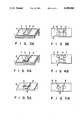
- FIG. 2Ashows a sediment particle distribution pattern obtained when there was an agglutination reaction in an agglutination test carried out using the reaction vessel kit shown in FIGS. 1A-1C;
- FIG. 2Bshows a sediment particle distribution pattern obtained when there was no agglutination reaction in an agglutination test carried out using the reaction kit shown in FIGS. 1A-1C;
- FIG. 3Ais a perspective view of a modification with a different shape of spacer
- FIG. 3Bis a plan view of a part of the kit shown in FIG. 3A
- FIG. 4Ais a perspective view of another modification with a different shape of spacer
- FIG. 4Bis a plan view of a part of the kit shown in FIG. 4A;
- FIG. 5Ais a perspective view of a modification wherein the part of the kit defining the reaction zone is integrally formed with the supporting base;
- FIG. 5Bis a plan view of the kit shown in FIG. 5A;
- FIG. 6Ais a perspective view showing another modification wherein the part of the kit defining the reaction zone is integrally formed with the supporting base;
- FIG. 6Bis a plan view seen from direction Y2 of the kit shown in FIG. 6A;
- FIG. 6Cis a plan view seen from direction X2 of the kit shown in FIG. 6A;
- FIG. 7Ashows a sediment particle distribution pattern obtained when there was an agglutination reaction in an agglutination test carried out using the reaction kit shown in FIGS. 1A-1C wherein antibodies have been coated in the reaction zone;
- FIG. 7Bshows a sediment particle distribution pattern obtained when there was no agglutination reaction in an agglutination test carried out using the reaction kit shown in FIGS. 1A-1C wherein antibodies have been coated in the reaction zone;
- FIG. 8is a view showing a process in an agglutination test using the reaction kit shown in FIGS. 1A-1C;
- FIG. 9is a view showing another process in an agglutination test using the reaction kit shown in FIGS. 1A-1C.
- the reaction zoneis defined enclosed by two plates and spacers which maintain these plates at a small separation apart.
- the sampleis filled in the reaction zone.
- the liquid surface of the sample in the reaction zoneis therefore constantly in contact with the inner wall of the zone, and is maintained flat. For this reason, there is no disturbance of the particle distribution pattern.
- the cross-sectional area of the reaction zoneis such that the sample can be introduced into the reaction zone by capillarity, and is extremely small. For this reason, the distance over which the sedimented particles move is much shorter, and the distribution pattern can be formed in a short time.
- sampleis introduced by means of capillarity, and may for example be dropped into the opening of the reaction zone.
- the quantity of sample solution in the reaction zoneis always constant regardless of the quantity dropped in, and it is not therefore particularly essential to pipette small quantities accurately.
- FIG. 1Ais a perspective view of the reaction kit of this invention
- FIG. 1Bis a plan view seen from direction X1 of the reaction zone defining means shown in FIG. 1A
- FIG. 1Cis a sectional view of the portion of the reaction kit shown in FIG. 1B.
- the reaction zoneis defined by a lower plate 2 and an upper plate 4 which preferably consist of transparent members, and which are arranged substantially parallel to each other on either side of two spacers 3.
- the area 5 enclosed by lower plate 2, upper plate 4 and the two spacersis the reaction zone where agglutination reactions are carried out, and it is also a sample inlet channel for introducing the sample.
- the two sides where spacers 3 are not insertedconstitute a sample inlet port 12 from which the sample is injected or exhausted.
- a supporting base 1is provided with an inclined surface at a specified angle with respect to the horizontal.
- the reaction zone defining means(the two plates 2, 4 and two spaces 3) is mounted on the inclined surface of this supporting base.
- the thickness of spacers 3, that is the distance between lower plate 2 and upper plate 4,is 0.05-1.0 mm, and that the distance between the two spacers 3 is 0.1-1.0 mm. Further, it is desirable that the length of the long direction of reaction zone 5, that is the width of upper plate 4, is 3-10 mm. It is moreover desirable that the slope of the inclined surface of the supporting base 1 is 10°-60° with respect to the horizontal.
- This reaction vessel kitmay be used in tests to verify the occurrence or non-occurrence of agglutination reactions.
- this kitis used to establish the occurrence of a reaction between blood corpuscles and antibodies in serum, the following procedure is carried out.
- a fixed concentration of a blood corpuscles suspension and a fixed dilution of serumare mixed in a test tube.
- the mixtureis then aspirated by a pipette, and a suitable quantity is dropped to sample inlet port 12 of the reaction zone.
- the mixturedropped spreads by capillarity throughout the reaction zone 5.
- the kitis allowed to stand undisturbed for a certain time, and blood corpuscles sediment out. Since the reaction zone is inclined, the sedimented corpuscles move downwards along inclined lower plate 2 without collecting on lower plate 2. From the blood corpuscles distribution pattern formed in the lower part of the reaction zone, it is then possible to verify the occurrence or non-occurrence of a reaction.
- a positive pattern 10is formed wherein the corpuscles ar spread uniformly to the upper part of inclined lower plate 2 as shown in FIG. 2A.
- a negative pattern 39is formed wherein the corpuscles are gathered in a line on the lowermost part of the reaction zone, as shown in FIG. 2B.
- the spacers 3are rectangular.
- the spacersneed not however be rectangular, and may also be of the form of spacers 6 and 7 shown in FIGS. 3A-4B.
- spacers of such a formthe sample inlet port is enlarged, and introduction of aliquot parts of sample is easier.
- reaction zone defining means and the supporting basemay be integrally molded.
- FIG. 5A and 5Bshow an integrated reaction kit of this type. As shown in these figures, a tubular reaction zone 5 of such a cross-sectional area as to permit aspiration of the sample by capillarity, is provided on the inclined surface 8, and sunken liquid troughs 9 are provided on both side edges of reaction zone 5.
- the integrated reaction kitmay also be molded in a rod shape.
- a reaction zone 32which is a throughhole having a specified angle with respect to the horizontal and a hollow 29 connected to this reaction zone 32.
- Reaction zone 32has a cross-sectional area such that the sample can be aspirated by capillarity.
- this rod-shape reaction kitis used in agglutination reaction tests, the following procedure is carried out. First, the end 30 of rod-shaped member 27 is dipped in a previously prepared particle suspension, and the particle suspension is thereby introduced into reaction zone 32 from sample inlet port 28 by means of capillarity.
- reaction zone 32is connected to hollow 29 and hollow 29 is connected to the outside via opening 31, so unnecessary pressure does not act on reaction zone 32. Further, by applying a negative pressure from opening 31, sample or wash solution may be forcibly aspirated. Reaction zone 32 may also be washed by introducing wash solution from opening 31, or simply by applying a positive pressure to opening 31.
- a sample of bloodis separated in test tube 13 into a blood corpuscle component 15 and blood serum component 14 by centrifugation or another suitable method. If the blood was treated with an anticoagulant such as heparin, the blood serum component 14 will be plasma.
- 2 ⁇ l of the blood corpuscle component 15 and 18 ⁇ l of a previously prepared solution 17 from container 16are mixed in a test tube 19, and are prereacted together.
- This solution 17consists of an anti-A serum dilution prepared by diluting standard anti-A serum (Orso Co.) to 1/30 with physiological saline.
- 5 ⁇ l of blood corpuscle suspension 18are pipetted by means of pipette 20 into reaction zone 5 of reaction zone defining means 21.
- the distance between lower plate 2 and upper plate 4is 80 ⁇ m
- the distance between the two spacers 3is 500 ⁇ m and the length of the long direction of reaction zone 5 is 250 ⁇ m
- a supporting basewherein the slope of the inclined surface is 45°
- all the human red blood cellssediment in the lower part of the reaction zone in about 10 minutes.
- the reaction zone defining means 21is set on supporting base 1, and the base is left in an incubator at 36° C. for about 10 minutes.
- the distance between the upper and lower plates and the distance between the two spacersare closely related to the time required to sediment the particles, and more specifically, should both be small in order to complete the sedimentation of particles in a short time. If however the distance between the two spacers is too small, the area where the particle distribution pattern is formed becomes smaller, and therefore the error of measurement increases. It is moreover necessary that the length of the long direction of the reaction zone is such that small quantities of the sample do not dry out during the reaction, and such that the sample can spread by capillarity throughout the whole of the reaction zone.
- the reaction means 21is transferred to the measurement area.
- the measurement areacomprises a light source 23 and a microscope optical system 25 to observe the blood corpuscle distribution pattern magnified, and it also has a photo sensor 26 to image the magnified blood corpuscle distribution in the reaction zone.
- the occurrence or non-occurrence of an antigen-antibody reactionis determined by magnifying the reaction zone 5 by means of optical system 25, and observing the blood corpuscle distribution pattern.
- the image obtained by photo sensor 26may be analyzed by a computer to determine the occurrence or non-occurrence of the reaction.
- the observed blood corpuscle distributionhas a pattern of the type shown in FIG. 2A, it indicates that there are A antigens on the surface of the blood corpuscles in the sample, and that the blood corpuscles have agglutinated due to anti-A antibodies If on the other hand the blood corpuscle distribution has a pattern of the type shown in FIG. 2B, it indicates that there are no antigens on the surface of the blood corpuscles in the sample, and that the cells moved freely down the sloping surface of the reaction kit.
- the reactivity of the sample with respect to anti-B serumis measured in the same way, and from its measured reactivity with respect to anti-A serum and anti-B serum, the blood group of the sample can be determined. If the blood corpuscles in the sample showed an antigen-antibody reaction with respect to both anti-A serum and anti-B serum, the blood group of the sample is AB; if there was a reaction only with respect to anti-A serum, the blood group of the sample is A; if there was a reaction only with respect to anti-B serum, the blood group of the sample is B; while if there was no reaction to either serum, the blood group of the sample is O.
- the determination of blood groupwhich previously required 60 minutes, can be accomplished in about 10 minutes using the reaction vessel kit of this invention.
- a sample of bloodis separated into a blood corpuscle component 15 and blood serum component 14 by centrifugation or another suitable method. If the blood was treated with an anticoagulant such as heparin, the blood serum component 14 will be plasma. After separation, 2 ⁇ l of the supernatant blood serum component 14 and 25 ⁇ l of a previously prepared solution 17 are mixed in a test tube 19, and prereacted together.
- This solution 17consists of sensitized particles diluted to 1.0 % (v/v) with physiological saline, organically synthesized peptides having an identical amino acid sequence to HIV antigen being coated on the surface of these sensitized particles.
- the sensitized particlesmay consist of synthetic particles of polystyrene or gelatin which have been modified chemically, animal red blood cells fixated by glutaraldehyde or the like, or similar particles.
- the antigen used to sensitize the particlesmay be an inactivated virus, or a recombinant protein produced by Escherichia coil or the like using gene manipulation techniques.
- the distribution of particles which have sedimented in reaction zone 5is observed using the same method as in Example 1. If the observed particle distribution gives a pattern of the type shown in FIG. 2A, it indicates that there are anti-HIV antibodies in the serum of the sample, and that the particles have agglutinated due to the anti-HIV antibodies. If on the other hand the particle distribution gives a pattern of the type shown in FIG. 2B, it indicates that there are no antibodies in the sample reacting to the surface antigens of the sensitized particles.
- an assaymay be carried out for viruses or bacteria other than HIV such as HTLV-1, HB or gonococcus. Further, using antibody-sensitized particles, an assay for antigen may be carried out for HBs, drugs or cancer markers. Further, if particles of several different colors are made to conjugate respectively with different antibodies or antigens, and for example a color CCD camera is used as photo sensor 26, assays for several antibodies or antigens may be carried out in one operation.
- an assaycan be thus be carried out with high sensitivity in 1/6 of the time conventionally required. Moreover, the assay may be performed using less of the costly particle reagent than was previously required.
- an antiserum against A antigens on the surface of blood corpusclesis coated in the reaction zone 5 of a reaction kit as shown in FIGS. 1A-1C using the method described below.
- Standard anti-A serum(Orso Co.) is diluted to 1/10 with 10 mM Tris-HCl buffer solution, pH 9, containing 0.15 M NaCl. 5 ul of the diluted solution is dropped to reaction zone 5 of lower plate 2. After dropping of the solution, the lower plate is incubated at 37° C. for 1 hour while maintaining humid conditions so that the solution does not dry out. The reaction zone 5 is then washed by dropping 10 mM phosphate buffer solution, pH 7.2, containing 0.15 M NaCl.
- reaction zone 5After removing the wash solution by gently shaking lower plate 2, 10 ml of 10 mM phosphate buffer solution, pH 7.2 containing 3% (w/v) of bovine serum albumin and 0.15 M NaCl are dropped to reaction zone 5, and the lower plate is incubated at room temperature while maintaining humid conditions for 1 hour. By this procedure, the area of the reaction zone which adsorbs blood corpuscles non-specifically is blocked. After incubation, reaction zone 5 is again washed with 10 mM phosphate buffer solution, pH 7.2, containing 0.15 M NaCl. If the lower plate is to be kept for a long period, 0.02% (w/v) NaN 3 is added to the final wash solution, and the lower plate is kept at 4° C. after washing.
- upper plate 4is also treated so that non-specific conjugation with blood corpuscles does not occur. This is done by leaving the upper plate at room temperature for 1 hour in 10 mM phosphate buffer solution, pH 7.2, containing 3% (w/v) bovine serum albumin and 0.15 M NaCl, and washing it with 10 mM phosphate buffer solution, pH 7.2, containing 0.15 M NaCl. If the upper plate is to be left for a long period, 0.02% (w/v) NaN 3 is added to the final wash solution, and the upper plate is kept at 4° C. as in the case of the lower plate. In addition to this lower plate 2 and upper plate 4, the reaction is assembled using two spacers 3 which are fixed by means of double-sided adhesive tape o adhesive.
- the spacersare of thickness 80 ⁇ m, the distance between the two spacers is 0.5 mm and the length of the long direction of the reaction zone is 5 mm, and a supporting base has inclination angle of 45°.
- a sample of bloodis separated into a blood corpuscle component 15 and blood serum component 14 by centrifugation or another suitable method. If the blood was treated with an anticoagulant such as heparin, the blood serum component 14 will be plasma.
- 2 ⁇ l of the sedimented blood corpuscle component 15 and 98 ⁇ l of a solution 17are mixed in a test tube 19 to prepare a 2% blood corpuscle suspension 18.
- solution 17is physiological saline.
- This blood corpuscle suspension 18is then introduced by means of a pipette 20 to reaction zone 5 wherein anti-A serum has been coated as described above.
- the reaction means 21is set on supporting base 1 and incubated at about 36° C. for 10 min, care being taken not to shake the reaction zone. The pipetting may be performed after setting of the reaction means 21 on the supporting base 1.
- the distribution pattern of particles sedimented in reaction zone 5is observed as in Example 1. If there are A antigens on the surface of the blood corpuscles in the sample, the corpuscles conjugate with the anti-A serum that was coated in the reaction zone, and the blood corpuscles are uniformly distributed practically all over reaction zone 5. The corpuscle distribution which appears in this case therefore gives a pattern 11 of the type shown in FIG. 7A. If on the other hand there are no A antigens on the surface of the corpuscles in the sample, the blood corpuscles do not conjugate with the anti-A serum coated in the reaction and the corpuscles move freely down the inclined lower plate 2.
- the distribution of blood corpusclesgives a pattern 12 of the type shown in FIG. 7B.
- a antigens on the surface of blood corpuscles in the samplemay be determined in the same way by measuring the reactivity of the sample with respect to anti-B serum.
- the blood group of the samplecan be determined. If the blood corpuscles in the sample showed an antigen-antibody reaction with respect to both anti-A serum and anti-B serum, the blood group of the sample is AB; if there was a reaction only with respect to anti-A serum, the blood group of the sample is A; if there was a reaction only with respect to anti-B serum, the blood group of the sample is B; while if there was no reaction to either serum, the blood group of the sample is O.
- the determination of blood groupwhich previously required 60 minutes, can be accomplished in about 10 minutes using the reaction kit of this invention.
- HIV antigensare coated in the reaction zone 5.
- the HIV antigens coated in the reaction zone 5may be chemically synthesized HIV virus surface antigens, HIV recombinant proteins produced by Escherichia coil, or the HIV virus itself.
- a sample of bloodis separated in test tube 13 into a blood corpuscle component 15 and blood serum component 14 by centrifugation or another suitable method. If the blood was treated with an anticoagulant such as heparin, the blood serum component 14 will be plasma. 2 ⁇ l of the serum component obtained was removed in a test-tube 19, then 18 ⁇ l of physiological saline was added and mixed with it. 5 ⁇ l of this diluted serum solution 27 was pipetted by means of pipette 34 to a reaction zone 5 wherein HIV antigens had been coated. After pipetting, the reaction zone means was set on supporting base 1 and was incubated at 37° C. for 2 min.
- reaction zone 5Following the reaction, physiological saline as wash solution was introduced by nozzle 35 into reaction zone 5 and waste liquid was aspirated simultaneously by nozzle 36 from the opposite side.
- physiological saline as wash solutionwas introduced by nozzle 35 into reaction zone 5 and waste liquid was aspirated simultaneously by nozzle 36 from the opposite side.
- the reaction zone 5can be washed, and the serum component which did not react with the antigen coated in reaction zone 5 can be washed out. It is desirable that wash solution remaining in reaction zone 5 is wiped off with filter paper, or eliminated by blowing in air from the nozzle.
- a particle reagent 33 to which goat antihuman antibodies had been coatedwas introduced by means of nozzle 37 to the reaction zone, and the apparatus was incubated at 37° C. for 10 min.
- the anti-human antibodies used heremay also be monoclonal antibodies derived from mouse or the like, or a substance such as protein A which binds to antibodies.
- the particles on which the antibodies are coatedmay be red blood cells fixated by glutaraldehyde or the like, or synthetic particles such as polystyrene.
- the particle distribution patternis observed by the same method as that of Example 1. If there are antibodies against for HIV in the serum of the sample, they conjugate with the HIV antigens coated in the reaction zone, and the particles to which anti-human antibodies have been coated conjugate with the antibodies which have conjugated with the antigens. The particle distribution is therefore a pattern of the type shown in FIG. 7A. If on the other hand there are no antibodies against HIV in the serum of the sample, the particles move freely down the inclined lower plate without causing an reaction. The particle distribution is therefore a pattern of the type shown in FIG. 7B.
- antibodies against viruses other than HIV such as HTLV-1 or HTLV-II or for bacteriamay also be detected.
- the antibodyusually has 2-10 antigen binding sites. Particles to which the same antigen has been coated as the antigen coated in the reaction zone, may therefore also be used as particle reagent 33.
- an assay for antigenmay also be carried out by the "sandwich” method wherein antibodies are coated in both the reaction zone and on the particles.
Landscapes
- Health & Medical Sciences (AREA)
- Chemical & Material Sciences (AREA)
- Immunology (AREA)
- Life Sciences & Earth Sciences (AREA)
- Engineering & Computer Science (AREA)
- Hematology (AREA)
- Biomedical Technology (AREA)
- Urology & Nephrology (AREA)
- Molecular Biology (AREA)
- Analytical Chemistry (AREA)
- General Health & Medical Sciences (AREA)
- Medicinal Chemistry (AREA)
- General Physics & Mathematics (AREA)
- Cell Biology (AREA)
- Microbiology (AREA)
- Chemical Kinetics & Catalysis (AREA)
- Pathology (AREA)
- Food Science & Technology (AREA)
- Biotechnology (AREA)
- Physics & Mathematics (AREA)
- Biochemistry (AREA)
- Dispersion Chemistry (AREA)
- Clinical Laboratory Science (AREA)
- Investigating Or Analysing Biological Materials (AREA)
- Automatic Analysis And Handling Materials Therefor (AREA)
Abstract
Description
This application is a continuation of application Ser. No. 07,458,143, filed Dec. 28, 1989, now abandoned.
1. Field of the Invention
This invention concerns a reaction kit for carrying out agglutination reactions, and in particular, a reaction kit used for hemanalysis involving immunological antigen-antibody reactions.
2. Description of the Related Art
Conventional reaction vessels used for detections by using immunological agglutination reactions are, for example, of the type disclosed in U.S. Pat. No. 4,303,616. These reaction vessels are usually referred to by the generic name of microplates.
One detection method using this kind of reaction vessel is a is particle agglutination method whereby antigens or antibodies in the sample are detected based on an immunological agglutination reaction. In this method, a specific marker particle is used and antigens or antibodies which conjugate specifically to the substance being measured are coated on the surface of the particle. To detect viruses in blood, for example, a man-made marker particle on which the antibodies against the virus are coated is used. The method is carried out using said reaction vessel as follows. First, said marker particles are mixed with the sample in the reaction vessel, an immunological reaction takes place with the antigens or antibodies in the sample, and the marker particles collect on one of the walls (for example the bottom) of the reaction vessel. The particles collected on the wall of the vessel however have a different distribution pattern depending on whether there was or was not an immunological reaction with the substance being measured in the sample. It is therefore possible to determine a positive or negative reaction for the substance from the distribution pattern of marker particles on the wall of the vessel.
Another method, the mixed agglutination method, was reported by A. S. Wiener and M. H. Herman. This method was subsequently improved in stages so that it could even determine blood group. To determine blood group, for example, the following procedure is carried out using said reaction vessel. First, suitable quantities of a fixed concentration of red blood cells and a fixed dilution of serum are mixed in the reaction vessel, and allowed to stand for a certain time. As in the method described above, the distribution pattern of sedimented red blood cells is different according to whether there was or was not an immunological reaction between antigens on the red blood cells, and antibodies in the serum. It is therefore possible to determine a positive or negative reaction from the distribution pattern of sedimented red blood cells.
The distribution pattern obtained by these methods can be easily observed with the naked eye, but it may also be analyzed automatically by the methods disclosed in Unexamined Published Japanese Patent Application No. 54-78499. Further, in Examined Japanese Utility Model No. 61-39321, a method is disclosed whereby a particle agglutination pattern is formed on an optically flat focus plane, and the agglutination image is easily observed.
In the reaction vessel described in U.S. Pat. No. 4,303,616, however, at least about 50 μl of liquid is required to form a stable and accurate distribution pattern. If the quantity of liquid is less than 50 μl, the sedimentation of particles is disturbed and to be irregular due to surface tension, and the distribution pattern does not form correctly. For this reason, the depth of reaction solution in this reaction vessel requires no less than 3 mm. It is moreover for this reason that the distribution pattern takes a long time to form. In other words, the particles such as red blood cells which form the distribution pattern have to move over a considerable distance, and as a result, the time required to form the pattern is long.
The above problem, namely that the distribution pattern is not formed correctly when the quantity of liquid is too small, can be overcome to some extent by making the internal diameter of the reaction vessel smaller. In this case, however, the surface tension between the reaction solution and the walls of the reaction vessel comes into play, and the liquid surface again sinks or rises irregularly. The result is that it becomes difficult to accurately observe the distribution pattern which is formed.
Further, if the internal diameter of the vessel is made smaller so that the quantity of liquid become smaller, the time required to form the distribution pattern is shorter, but the problem then arises that it is necessary to handle minute quantities of reagent. In particular, when the quantity of liquid is no greater than 5 μl, it becomes extremely difficult technically to pipette reagents accurately with high reproducibility.
Further, very fine surface working is required to manufacture vessels of small internal diameter precisely, for example recesses with a diameter of the order of several hundred micrometers, and it is also difficult to manufacture them efficiently.
The method described in Examined Japanese Utility Model No. 61-39321, on the other hand, is a flow type measurement method which uses a rolling pump to introduce a particle suspension into the reaction vessel. The number of samples or items which can be measured simultaneously by such a flow type method is however limited, and it is impossible to simultaneously handle many samples over multiple items as in the method in which a conventional microplate is used. Further, there is a large error in introducing measured quantities of a sample by a rolling pump, and the method is not suited to the analysis of minute quantities of samples of the order of μm.
This invention aims to provide a reaction kit for agglutination reactions, wherein an accurate distribution pattern of sedimented particles is formed in a short time, and the distribution pattern obtained can be observed accurately.
Said objectives are achieved by a kit comprising a reaction zone defining means for defining a reaction zone suitable for aspirating the sample into the interior of the reaction zone by capillarity, the reaction zone defining means including a transparent plate with a flat surface in at least part of said reaction zone, and a supporting base to incline said reaction zone at a specified angle.
The reaction zone is generally a space formed by 2 transparent plates with flat surfaces, and 2 spacers inserted between these 2 plates at a specified distance from each other.
The supporting base inclines the reaction zone at a specified angle and maintains the angle. The reaction zone defining means is mounted on the base such that one of the sides into which a spacer has been inserted is in the lower position.
In the reaction kit of this invention, the sample is introduced by means of capillarity into the reaction zone from an opening of the reaction zone. The cross-sectional area of the reaction zone is therefore suitable for asp rating the sample into the interior of the reaction zone by capillarity. This cross-sectional area varies according to the sample being observed, but if the sample consists of blood components, it is preferably 0.2-5 mm2.
Fig 1A is a perspective view showing one embodiment of the reaction kit according to this invention;
FIG. 1B is a plan view seen from direction X1 of a part of the kit shown in FIG. 1A;
FIG. 1C is a cross-sectional view of the part of the kit shown in FIG. 1B;
FIG. 2A shows a sediment particle distribution pattern obtained when there was an agglutination reaction in an agglutination test carried out using the reaction vessel kit shown in FIGS. 1A-1C;
FIG. 2B shows a sediment particle distribution pattern obtained when there was no agglutination reaction in an agglutination test carried out using the reaction kit shown in FIGS. 1A-1C;
FIG. 3A is a perspective view of a modification with a different shape of spacer;
FIG. 3B is a plan view of a part of the kit shown in FIG. 3A
FIG. 4A is a perspective view of another modification with a different shape of spacer;
FIG. 4B is a plan view of a part of the kit shown in FIG. 4A;
FIG. 5A is a perspective view of a modification wherein the part of the kit defining the reaction zone is integrally formed with the supporting base;
FIG. 5B is a plan view of the kit shown in FIG. 5A;
FIG. 6A is a perspective view showing another modification wherein the part of the kit defining the reaction zone is integrally formed with the supporting base;
FIG. 6B is a plan view seen from direction Y2 of the kit shown in FIG. 6A;
FIG. 6C is a plan view seen from direction X2 of the kit shown in FIG. 6A;
FIG. 7A shows a sediment particle distribution pattern obtained when there was an agglutination reaction in an agglutination test carried out using the reaction kit shown in FIGS. 1A-1C wherein antibodies have been coated in the reaction zone;
FIG. 7B shows a sediment particle distribution pattern obtained when there was no agglutination reaction in an agglutination test carried out using the reaction kit shown in FIGS. 1A-1C wherein antibodies have been coated in the reaction zone;
FIG. 8 is a view showing a process in an agglutination test using the reaction kit shown in FIGS. 1A-1C; and
FIG. 9 is a view showing another process in an agglutination test using the reaction kit shown in FIGS. 1A-1C.
As described above, in the reaction kit according to this invention, the reaction zone is defined enclosed by two plates and spacers which maintain these plates at a small separation apart. Also, to carry out the reaction, the sample is filled in the reaction zone. The liquid surface of the sample in the reaction zone is therefore constantly in contact with the inner wall of the zone, and is maintained flat. For this reason, there is no disturbance of the particle distribution pattern. In addition, the cross-sectional area of the reaction zone is such that the sample can be introduced into the reaction zone by capillarity, and is extremely small. For this reason, the distance over which the sedimented particles move is much shorter, and the distribution pattern can be formed in a short time.
Further, the sample is introduced by means of capillarity, and may for example be dropped into the opening of the reaction zone. The quantity of sample solution in the reaction zone is always constant regardless of the quantity dropped in, and it is not therefore particularly essential to pipette small quantities accurately.
We shall now describe some embodiments of the reaction kit according to this invention with reference to the drawings.
FIG. 1A is a perspective view of the reaction kit of this invention; FIG. 1B is a plan view seen from direction X1 of the reaction zone defining means shown in FIG. 1A; and FIG. 1C is a sectional view of the portion of the reaction kit shown in FIG. 1B. As shown in these figures, in the reaction zone is defined by alower plate 2 and anupper plate 4 which preferably consist of transparent members, and which are arranged substantially parallel to each other on either side of twospacers 3. Thearea 5 enclosed bylower plate 2,upper plate 4 and the two spacers is the reaction zone where agglutination reactions are carried out, and it is also a sample inlet channel for introducing the sample. The two sides wherespacers 3 are not inserted constitute asample inlet port 12 from which the sample is injected or exhausted. A supportingbase 1 is provided with an inclined surface at a specified angle with respect to the horizontal. The reaction zone defining means (the twoplates
In this kit, it is desirable that the thickness ofspacers 3, that is the distance betweenlower plate 2 andupper plate 4, is 0.05-1.0 mm, and that the distance between the twospacers 3 is 0.1-1.0 mm. Further, it is desirable that the length of the long direction ofreaction zone 5, that is the width ofupper plate 4, is 3-10 mm. It is moreover desirable that the slope of the inclined surface of the supportingbase 1 is 10°-60° with respect to the horizontal.
This reaction vessel kit may be used in tests to verify the occurrence or non-occurrence of agglutination reactions. In the case where, for example, this kit is used to establish the occurrence of a reaction between blood corpuscles and antibodies in serum, the following procedure is carried out.
First, a fixed concentration of a blood corpuscles suspension and a fixed dilution of serum are mixed in a test tube. The mixture is then aspirated by a pipette, and a suitable quantity is dropped to sampleinlet port 12 of the reaction zone. The mixture dropped spreads by capillarity throughout thereaction zone 5. The kit is allowed to stand undisturbed for a certain time, and blood corpuscles sediment out. Since the reaction zone is inclined, the sedimented corpuscles move downwards along inclinedlower plate 2 without collecting onlower plate 2. From the blood corpuscles distribution pattern formed in the lower part of the reaction zone, it is then possible to verify the occurrence or non-occurrence of a reaction. If the corpuscles agglutinated due to an antigen-antibody reaction, apositive pattern 10 is formed wherein the corpuscles ar spread uniformly to the upper part of inclinedlower plate 2 as shown in FIG. 2A. On the other hand if there was no reaction and the corpuscles did not agglutinate, all the corpuscles move down inclinedlower plate 2, and anegative pattern 39 is formed wherein the corpuscles are gathered in a line on the lowermost part of the reaction zone, as shown in FIG. 2B.
In the reaction kit shown in FIGS. 1A -1C, thespacers 3 are rectangular. The spacers need not however be rectangular, and may also be of the form ofspacers
In the reaction vessel kit of this invention, the reaction zone defining means and the supporting base may be integrally molded. FIG. 5A and 5B show an integrated reaction kit of this type. As shown in these figures, atubular reaction zone 5 of such a cross-sectional area as to permit aspiration of the sample by capillarity, is provided on theinclined surface 8, and sunkenliquid troughs 9 are provided on both side edges ofreaction zone 5.
The integrated reaction kit may also be molded in a rod shape. In the rectangular rod-shapedreaction kit 27 shown in FIGS. 6A-6C, there are provided areaction zone 32 which is a throughhole having a specified angle with respect to the horizontal and a hollow 29 connected to thisreaction zone 32.Reaction zone 32 has a cross-sectional area such that the sample can be aspirated by capillarity. In the case where this rod-shape reaction kit is used in agglutination reaction tests, the following procedure is carried out. First, theend 30 of rod-shapedmember 27 is dipped in a previously prepared particle suspension, and the particle suspension is thereby introduced intoreaction zone 32 fromsample inlet port 28 by means of capillarity. After the suspension has been introduced into the reaction zone,member 27 is removed from the suspension, and laid horizontally to allow the reaction to proceed undisturbed for 10 min. After the reaction, by observing the particle distribution pattern formed inreaction zone 32, it is possible to determine whether there was or was not an agglutination reaction. In this rod-shaped reaction kit,reaction zone 32 is connected to hollow 29 and hollow 29 is connected to the outside via opening 31, so unnecessary pressure does not act onreaction zone 32. Further, by applying a negative pressure from opening 31, sample or wash solution may be forcibly aspirated.Reaction zone 32 may also be washed by introducing wash solution from opening 31, or simply by applying a positive pressure toopening 31.
We shall now describe some agglutination tests using the reaction kit according to this invention.
We shall describe the determination of human ABO blood group using the reaction kit of FIGS. 1A-1C with reference to FIG. 8.
First, a sample of blood is separated intest tube 13 into ablood corpuscle component 15 and blood serum component 14 by centrifugation or another suitable method. If the blood was treated with an anticoagulant such as heparin, the blood serum component 14 will be plasma. Next, 2 μl of theblood corpuscle component container 16 are mixed in atest tube 19, and are prereacted together. This solution 17 consists of an anti-A serum dilution prepared by diluting standard anti-A serum (Orso Co.) to 1/30 with physiological saline. After the preliminary reaction, 5 μl ofblood corpuscle suspension 18 are pipetted by means ofpipette 20 intoreaction zone 5 of reactionzone defining means 21. Where the distance betweenlower plate 2 andupper plate 4 is 80 μm, the distance between the twospacers 3 is 500 μm and the length of the long direction ofreaction zone 5 is 250 μm, and a supporting base wherein the slope of the inclined surface is 45°, all the human red blood cells sediment in the lower part of the reaction zone in about 10 minutes. After pipettingblood corpuscle suspension 18, therefore, the reactionzone defining means 21 is set on supportingbase 1, and the base is left in an incubator at 36° C. for about 10 minutes.
The distance between the upper and lower plates and the distance between the two spacers are closely related to the time required to sediment the particles, and more specifically, should both be small in order to complete the sedimentation of particles in a short time. If however the distance between the two spacers is too small, the area where the particle distribution pattern is formed becomes smaller, and therefore the error of measurement increases. It is moreover necessary that the length of the long direction of the reaction zone is such that small quantities of the sample do not dry out during the reaction, and such that the sample can spread by capillarity throughout the whole of the reaction zone.
After the reaction zone defining is complete, the reaction means 21 is transferred to the measurement area. The measurement area comprises alight source 23 and a microscopeoptical system 25 to observe the blood corpuscle distribution pattern magnified, and it also has aphoto sensor 26 to image the magnified blood corpuscle distribution in the reaction zone. The occurrence or non-occurrence of an antigen-antibody reaction is determined by magnifying thereaction zone 5 by means ofoptical system 25, and observing the blood corpuscle distribution pattern. Alternatively instead of observing the pattern with the naked eye, the image obtained byphoto sensor 26 may be analyzed by a computer to determine the occurrence or non-occurrence of the reaction.
If the observed blood corpuscle distribution has a pattern of the type shown in FIG. 2A, it indicates that there are A antigens on the surface of the blood corpuscles in the sample, and that the blood corpuscles have agglutinated due to anti-A antibodies If on the other hand the blood corpuscle distribution has a pattern of the type shown in FIG. 2B, it indicates that there are no antigens on the surface of the blood corpuscles in the sample, and that the cells moved freely down the sloping surface of the reaction kit.
The reactivity of the sample with respect to anti-B serum is measured in the same way, and from its measured reactivity with respect to anti-A serum and anti-B serum, the blood group of the sample can be determined. If the blood corpuscles in the sample showed an antigen-antibody reaction with respect to both anti-A serum and anti-B serum, the blood group of the sample is AB; if there was a reaction only with respect to anti-A serum, the blood group of the sample is A; if there was a reaction only with respect to anti-B serum, the blood group of the sample is B; while if there was no reaction to either serum, the blood group of the sample is O.
The determination of blood group, which previously required 60 minutes, can be accomplished in about 10 minutes using the reaction vessel kit of this invention.
We shall describe an assay for anti-HIV antibody using the reaction kit of FIGS. 1A-1C with reference to FIG. 8.
First, a sample of blood is separated into ablood corpuscle component 15 and blood serum component 14 by centrifugation or another suitable method. If the blood was treated with an anticoagulant such as heparin, the blood serum component 14 will be plasma. After separation, 2 μl of the supernatantblood serum component 14 and 25 μl of a previously prepared solution 17 are mixed in atest tube 19, and prereacted together. This solution 17 consists of sensitized particles diluted to 1.0 % (v/v) with physiological saline, organically synthesized peptides having an identical amino acid sequence to HIV antigen being coated on the surface of these sensitized particles. The sensitized particles may consist of synthetic particles of polystyrene or gelatin which have been modified chemically, animal red blood cells fixated by glutaraldehyde or the like, or similar particles. The antigen used to sensitize the particles may be an inactivated virus, or a recombinant protein produced by Escherichia coil or the like using gene manipulation techniques. When the preliminary reaction is complete, 5 μl of a suspension of the sensitized particles is pipetted toreaction zone 5 by means ofpipette 20, and the reaction means 21 is set on supportingbase 1, and the base is left in incubator at 25°-37° C. for 10 min.
After the reaction is complete, the distribution of particles which have sedimented inreaction zone 5 is observed using the same method as in Example 1. If the observed particle distribution gives a pattern of the type shown in FIG. 2A, it indicates that there are anti-HIV antibodies in the serum of the sample, and that the particles have agglutinated due to the anti-HIV antibodies. If on the other hand the particle distribution gives a pattern of the type shown in FIG. 2B, it indicates that there are no antibodies in the sample reacting to the surface antigens of the sensitized particles.
By varying the type of antigen coated on the particles, an assay may be carried out for viruses or bacteria other than HIV such as HTLV-1, HB or gonococcus. Further, using antibody-sensitized particles, an assay for antigen may be carried out for HBs, drugs or cancer markers. Further, if particles of several different colors are made to conjugate respectively with different antibodies or antigens, and for example a color CCD camera is used asphoto sensor 26, assays for several antibodies or antigens may be carried out in one operation.
Using the reaction kit of this invention, an assay can be thus be carried out with high sensitivity in 1/6 of the time conventionally required. Moreover, the assay may be performed using less of the costly particle reagent than was previously required.
Firstly, an antiserum against A antigens on the surface of blood corpuscles is coated in thereaction zone 5 of a reaction kit as shown in FIGS. 1A-1C using the method described below.
First, standard anti-A serum (Orso Co.) is diluted to 1/10 with 10 mM Tris-HCl buffer solution,pH 9, containing 0.15 M NaCl. 5 ul of the diluted solution is dropped toreaction zone 5 oflower plate 2. After dropping of the solution, the lower plate is incubated at 37° C. for 1 hour while maintaining humid conditions so that the solution does not dry out. Thereaction zone 5 is then washed by dropping 10 mM phosphate buffer solution, pH 7.2, containing 0.15 M NaCl. After removing the wash solution by gently shakinglower plate reaction zone 5, and the lower plate is incubated at room temperature while maintaining humid conditions for 1 hour. By this procedure, the area of the reaction zone which adsorbs blood corpuscles non-specifically is blocked. After incubation,reaction zone 5 is again washed with 10 mM phosphate buffer solution, pH 7.2, containing 0.15 M NaCl. If the lower plate is to be kept for a long period, 0.02% (w/v) NaN3 is added to the final wash solution, and the lower plate is kept at 4° C. after washing. Moreover, in addition tolower plate 2,upper plate 4 is also treated so that non-specific conjugation with blood corpuscles does not occur. This is done by leaving the upper plate at room temperature for 1 hour in 10 mM phosphate buffer solution, pH 7.2, containing 3% (w/v) bovine serum albumin and 0.15 M NaCl, and washing it with 10 mM phosphate buffer solution, pH 7.2, containing 0.15 M NaCl. If the upper plate is to be left for a long period, 0.02% (w/v) NaN3 is added to the final wash solution, and the upper plate is kept at 4° C. as in the case of the lower plate. In addition to thislower plate 2 andupper plate 4, the reaction is assembled using twospacers 3 which are fixed by means of double-sided adhesive tape o adhesive.
We shall now describe, with reference to FIG. 8, the direct cross-match test for ABO group using a reaction kit wherein an antiserum has been coated. in the kit used there, the spacers are of thickness 80 μm, the distance between the two spacers is 0.5 mm and the length of the long direction of the reaction zone is 5 mm, and a supporting base has inclination angle of 45°.
First, a sample of blood is separated into ablood corpuscle component 15 and blood serum component 14 by centrifugation or another suitable method. If the blood was treated with an anticoagulant such as heparin, the blood serum component 14 will be plasma. Next, 2 μl of the sedimentedblood corpuscle component 15 and 98 μl of a solution 17 are mixed in atest tube 19 to prepare a 2%blood corpuscle suspension 18. In this case, solution 17 is physiological saline. Thisblood corpuscle suspension 18 is then introduced by means of apipette 20 toreaction zone 5 wherein anti-A serum has been coated as described above. After pipetting, the reaction means 21 is set on supportingbase 1 and incubated at about 36° C. for 10 min, care being taken not to shake the reaction zone. The pipetting may be performed after setting of the reaction means 21 on the supportingbase 1.
After the reaction is complete, the distribution pattern of particles sedimented inreaction zone 5 is observed as in Example 1. If there are A antigens on the surface of the blood corpuscles in the sample, the corpuscles conjugate with the anti-A serum that was coated in the reaction zone, and the blood corpuscles are uniformly distributed practically all overreaction zone 5. The corpuscle distribution which appears in this case therefore gives apattern 11 of the type shown in FIG. 7A. If on the other hand there are no A antigens on the surface of the corpuscles in the sample, the blood corpuscles do not conjugate with the anti-A serum coated in the reaction and the corpuscles move freely down the inclinedlower plate 2. In this case, therefore, the distribution of blood corpuscles gives apattern 12 of the type shown in FIG. 7B. In this way, from the difference in the distribution pattern after reaction, it is possible to determine the presence or absence of A antigens on the surface of blood corpuscles in the sample. The presence or absence of B antigens on the surface of the blood corpuscles may be determined in the same way by measuring the reactivity of the sample with respect to anti-B serum.
From its measured reactivity with respect to anti-A serum and anti-B serum, the blood group of the sample can be determined. If the blood corpuscles in the sample showed an antigen-antibody reaction with respect to both anti-A serum and anti-B serum, the blood group of the sample is AB; if there was a reaction only with respect to anti-A serum, the blood group of the sample is A; if there was a reaction only with respect to anti-B serum, the blood group of the sample is B; while if there was no reaction to either serum, the blood group of the sample is O.
The determination of blood group, which previously required 60 minutes, can be accomplished in about 10 minutes using the reaction kit of this invention.
Assays for various antibodies can be carried out using a reaction kit wherein antigens have been coated instead of the anti-serum of Example 3. We shall describe an assay for anti-HIV antibody using such a method with reference to FIG. 9.
Firstly, using a similar method to that described in Example 3, HIV antigens are coated in thereaction zone 5. The HIV antigens coated in thereaction zone 5 may be chemically synthesized HIV virus surface antigens, HIV recombinant proteins produced by Escherichia coil, or the HIV virus itself.
Next, a sample of blood is separated intest tube 13 into ablood corpuscle component 15 and blood serum component 14 by centrifugation or another suitable method. If the blood was treated with an anticoagulant such as heparin, the blood serum component 14 will be plasma. 2 μl of the serum component obtained was removed in a test-tube 19, then 18 μl of physiological saline was added and mixed with it. 5 μl of this dilutedserum solution 27 was pipetted by means ofpipette 34 to areaction zone 5 wherein HIV antigens had been coated. After pipetting, the reaction zone means was set on supportingbase 1 and was incubated at 37° C. for 2 min. Following the reaction, physiological saline as wash solution was introduced bynozzle 35 intoreaction zone 5 and waste liquid was aspirated simultaneously bynozzle 36 from the opposite side. By this procedure thereaction zone 5 can be washed, and the serum component which did not react with the antigen coated inreaction zone 5 can be washed out. It is desirable that wash solution remaining inreaction zone 5 is wiped off with filter paper, or eliminated by blowing in air from the nozzle.
Next, aparticle reagent 33 to which goat antihuman antibodies had been coated, was introduced by means ofnozzle 37 to the reaction zone, and the apparatus was incubated at 37° C. for 10 min. The anti-human antibodies used here may also be monoclonal antibodies derived from mouse or the like, or a substance such as protein A which binds to antibodies. Further, the particles on which the antibodies are coated may be red blood cells fixated by glutaraldehyde or the like, or synthetic particles such as polystyrene.
After the reaction is complete, the particle distribution pattern is observed by the same method as that of Example 1. If there are antibodies against for HIV in the serum of the sample, they conjugate with the HIV antigens coated in the reaction zone, and the particles to which anti-human antibodies have been coated conjugate with the antibodies which have conjugated with the antigens. The particle distribution is therefore a pattern of the type shown in FIG. 7A. If on the other hand there are no antibodies against HIV in the serum of the sample, the particles move freely down the inclined lower plate without causing an reaction. The particle distribution is therefore a pattern of the type shown in FIG. 7B.
Using this reaction kit, a high sensitivity assay can be performed in a much shorter time than the 60-120 min previously required.
By varying the type of antigen coated in the reaction zone, antibodies against viruses other than HIV such as HTLV-1 or HTLV-II or for bacteria may also be detected. Further, the antibody usually has 2-10 antigen binding sites. Particles to which the same antigen has been coated as the antigen coated in the reaction zone, may therefore also be used asparticle reagent 33. Further, an assay for antigen may also be carried out by the "sandwich" method wherein antibodies are coated in both the reaction zone and on the particles.
Claims (13)
1. A reaction kit for observation and detection of a particle pattern due to an agglutination reaction, comprising:
reaction zone defining means for receiving a sample, said reaction zone defining means comprising:
two plates arranged opposed to each other, at least one of said plates being transparent for visual detection therethrough of a particle pattern formed in said reaction zone; and
spacers inserted between said two plates so as to maintain said two plates in spaced apart relation to each other, said reaction zone being defined in a space between said two plates and between said spacers; and
a supporting base for supporting said reaction zone defining means, and including means for inclining said reaction zone defining means at a specified angle to thereby incline said reaction zone, such that one of said spacers forms a bottom portion of the inclined reaction zone;
a part of the space defined between said two plates and between said spacers serving as an opening through which a sample is introduced into said reaction zone, and wherein said opening is located in a position different from said spacer forming the bottom portion of the inclined reaction zone;
wherein a sample is aspirated into said reaction zone when the sample is applied to said reaction zone defining means.
2. The reaction kit of claim 1, wherein said two plates are both transparent.
3. The reaction kit of claim 1, wherein said reaction zone defining means and said supporting base are integrally formed as one unit.
4. The reaction kit of claim 1, wherein said reaction zone defining means includes a bottom surface facing said reaction zone, and further comprises a substance with specific bonding affinity to a sample, coated on at least said bottom surface of said reaction zone defining means.
5. The reaction kit of claim 1, wherein said spacers comprises two spaced apart spacers inserted between said two plates, said two spacers being spaced apart in a direction parallel to said two plates, and the reaction zone being defined in the space between said two spacers.
6. The reaction kit of claim 5, wherein said spacers are substantially flat plates.
7. The reaction kit of claim 5, wherein said reaction zone defining means defines said reaction zone having a substantially rectangular cross-section.
8. The reaction kit of claim 5, wherein said reaction zone defining means said reaction zone having a substantially rectangular cross-section.
9. The reaction kit of claim 1, wherein said spacers include surface means for defining an inlet port in flow communication with said reaction zone, said inlet port having a greater cross-sectional area than said reaction zone.
10. The reaction kit of claim 9, wherein said spacers comprise two spaced apart spacer plates inserted between said two plates, said two spacers being spaced apart in a direction parallel to said two plates, and the reaction zone being defined in the space between said two spacers, at least one of said spacer plates having an angled surface to define an inlet port in flow communication with said reaction zone, said inlet port having a greater cross-sectional area than said reaction zone.
11. The reaction kit of claim 1, wherein said reaction zone defining means further comprises:
means defining a trough adjacent said reaction zone.
12. The reaction kit of claim 11, wherein said reaction zone; and
means defining a trough adjacent the opposite openings of said reaction zone.
13. A method of determining a degree of particle agglutination by an agglutination reaction having the reaction kit according to claim 1, the method comprising:
preparing a particle suspension containing particles with specific bonding properties and a substance with specific bonding affinity to the particles;
introducing the particle suspension into a reaction zone of said reaction kit according to claim 1;
setting said reaction zone defining means on said supporting base, and leaving said reaction zone defining means, with the particle suspension therein, on said supporting base for a predetermined time; and
observing the formation and degree of spread of a particle distribution pattern formed in a lower part of said reaction zone defined by said reaction zone defining means.
Priority Applications (1)
| Application Number | Priority Date | Filing Date | Title |
|---|---|---|---|
| US07/841,769US5188968A (en) | 1989-12-28 | 1992-03-02 | Method and reaction kit for agglutination detection |
Applications Claiming Priority (2)
| Application Number | Priority Date | Filing Date | Title |
|---|---|---|---|
| US45814389A | 1989-12-28 | 1989-12-28 | |
| US07/841,769US5188968A (en) | 1989-12-28 | 1992-03-02 | Method and reaction kit for agglutination detection |
Related Parent Applications (1)
| Application Number | Title | Priority Date | Filing Date |
|---|---|---|---|
| US45814389AContinuation | 1989-12-28 | 1989-12-28 |
Publications (1)
| Publication Number | Publication Date |
|---|---|
| US5188968Atrue US5188968A (en) | 1993-02-23 |
Family
ID=27038876
Family Applications (1)
| Application Number | Title | Priority Date | Filing Date |
|---|---|---|---|
| US07/841,769Expired - LifetimeUS5188968A (en) | 1989-12-28 | 1992-03-02 | Method and reaction kit for agglutination detection |
Country Status (1)
| Country | Link |
|---|---|
| US (1) | US5188968A (en) |
Cited By (41)
| Publication number | Priority date | Publication date | Assignee | Title |
|---|---|---|---|---|
| US5399316A (en)* | 1992-03-13 | 1995-03-21 | Olympus Optical Co., Ltd. | Reaction vessel for conducting an immunological assay |
| US5399317A (en)* | 1993-07-16 | 1995-03-21 | California Institute Of Technology | Reaction cell for protein sequencer and the like |
| US5541417A (en)* | 1995-05-18 | 1996-07-30 | Abbott Laboratories | Quantative agglutination reaction analysis method |
| US6309827B1 (en) | 1997-03-28 | 2001-10-30 | Orasure Technologies, Inc. | Simultaneous collection of DNA and non-nucleic analytes |
| WO2002004924A1 (en)* | 2000-07-10 | 2002-01-17 | Innovatis Ag. | Method for the examination of cells in a culture medium |
| US6458326B1 (en) | 1999-11-24 | 2002-10-01 | Home Diagnostics, Inc. | Protective test strip platform |
| US6525330B2 (en) | 2001-02-28 | 2003-02-25 | Home Diagnostics, Inc. | Method of strip insertion detection |
| US20030054427A1 (en)* | 1986-08-13 | 2003-03-20 | Roger Phillips | Minimum procedure system for the determination of analytes |
| US6541266B2 (en) | 2001-02-28 | 2003-04-01 | Home Diagnostics, Inc. | Method for determining concentration of an analyte in a test strip |
| US6562625B2 (en) | 2001-02-28 | 2003-05-13 | Home Diagnostics, Inc. | Distinguishing test types through spectral analysis |
| EP1062507A4 (en)* | 1998-03-07 | 2005-02-09 | Stephen C Wardlaw | DETERMINATION OF THE LEUKOCYTIC DIFFERENTIAL AND RETICULOCYTIC COUNTING |
| US20050079484A1 (en)* | 2003-10-10 | 2005-04-14 | Heineman William Richard | Method of detecting biological materials in liquid |
| US20090253218A1 (en)* | 2008-04-02 | 2009-10-08 | Abbott Point Of Care, Inc. | Method for serologic agglutination and other immunoassays performed in a thin film fluid sample |
| US10132794B2 (en) | 2015-09-14 | 2018-11-20 | Essenlix Corporation | Device and system for collecting and analyzing vapor condensate, particularly exhaled breath condensate, as well as method of using the same |
| US10324009B2 (en) | 2015-08-10 | 2019-06-18 | Essenlix Corporation | Bio/chemical assay devices and methods for simplified steps, small samples, accelerated speed, and ease-of-use |
| US10605805B2 (en) | 2015-09-14 | 2020-03-31 | Essenlix Corporation | Device and system for analyzing a sample, particularly blood, as well as methods of using the same |
| US10628693B2 (en) | 2016-12-21 | 2020-04-21 | Essenlix Corporation | Devices and methods for authenticating a sample and use of the same |
| US10807095B2 (en) | 2017-10-26 | 2020-10-20 | Essenlix Corporation | Making and tracking assay card |
| US11156606B2 (en) | 2018-01-11 | 2021-10-26 | Essenlix Corporation | Homogeneous assay (II) |
| US11237113B2 (en) | 2017-10-26 | 2022-02-01 | Essenlix Corporation | Rapid pH measurement |
| US11243201B2 (en) | 2017-08-01 | 2022-02-08 | Essenlix Corporation | Sample collection, holding and assaying |
| US11274996B2 (en) | 2017-02-07 | 2022-03-15 | Essenlix Corporation | Compressed open flow assay and use |
| US11280706B2 (en) | 2017-08-01 | 2022-03-22 | Essenlix Corporation | Dilution calibration |
| US11393561B2 (en) | 2017-10-13 | 2022-07-19 | Essenlix Corporation | Devices and methods for authenticating a medical test and use of the same |
| US11510608B2 (en) | 2017-12-14 | 2022-11-29 | Essenlix Corporation | Devices, systems, and methods for monitoring hair |
| US11523752B2 (en) | 2017-02-16 | 2022-12-13 | Essenlix Corporation | Assay for vapor condensates |
| US11604148B2 (en) | 2017-02-09 | 2023-03-14 | Essenlix Corporation | Colorimetric assays |
| US11609224B2 (en) | 2017-10-26 | 2023-03-21 | Essenlix Corporation | Devices and methods for white blood cell analyses |
| WO2023076188A1 (en)* | 2021-10-25 | 2023-05-04 | Massachusetts Institute Of Technology | Analyte detection systems and methods of use |
| US11648551B2 (en) | 2017-12-12 | 2023-05-16 | Essenlix Corporation | Sample manipulation and assay with rapid temperature change |
| US11725227B2 (en) | 2017-08-01 | 2023-08-15 | Essenlix Corporation | Devices and methods for examining drug effects on microorganisms |
| US11883824B2 (en) | 2017-02-09 | 2024-01-30 | Essenlix Corporation | Assay using different spacing heights |
| US11885952B2 (en) | 2018-07-30 | 2024-01-30 | Essenlix Corporation | Optics, device, and system for assaying and imaging |
| US11927560B2 (en) | 2017-02-08 | 2024-03-12 | Essenlix Corporation | Bio/chemical material extraction and assay |
| US11940382B2 (en) | 2017-02-09 | 2024-03-26 | Essenlix Corporation | Assay with amplification |
| US12007315B2 (en) | 2017-02-08 | 2024-06-11 | Essenlix Corporation | Sample collection and handling for delayed analysis |
| US12066434B2 (en) | 2017-02-08 | 2024-08-20 | Essenlix Corporation | QMAX assays and applications |
| US12151246B2 (en) | 2017-02-08 | 2024-11-26 | Essenlix Corporation | Molecular manipulation and assay with controlled temperature |
| US12181472B2 (en) | 2017-06-12 | 2024-12-31 | Essenlix Corporation | Homogeneous assay |
| US12350680B2 (en) | 2017-02-15 | 2025-07-08 | Essenlix Corporation | Assay with rapid temperature change |
| US12403465B2 (en) | 2017-10-11 | 2025-09-02 | Essenlix Corporation | Containing a liquid sample |
Citations (13)
| Publication number | Priority date | Publication date | Assignee | Title |
|---|---|---|---|---|
| JPS562559A (en)* | 1979-06-21 | 1981-01-12 | Olympus Optical Co Ltd | Detector for particle coagulation pattern |
| EP0034049A1 (en)* | 1980-02-06 | 1981-08-19 | EASTMAN KODAK COMPANY (a New Jersey corporation) | Test device for analysis of a plurality of analytes |
| US4303616A (en)* | 1979-06-20 | 1981-12-01 | Olympus Optical Co. Ltd. | Agglutination analyzing vessel |
| EP0057110A2 (en)* | 1981-01-28 | 1982-08-04 | EASTMAN KODAK COMPANY (a New Jersey corporation) | Reaction vessel and method for combining liquids and reagents |
| US4436827A (en)* | 1981-07-30 | 1984-03-13 | Olympus Optical Co. Ltd. | Detecting particle agglutination with vessel having inclined, stepped bottom surface |
| DE3438245A1 (en)* | 1983-10-18 | 1985-05-23 | Olympus Optical Co., Ltd., Tokio/Tokyo | METHOD FOR EVALUATING AN IMMUNOLOGICAL REACTION AND REACTIVE TUBE SUITABLE FOR THIS |
| JPS6139321A (en)* | 1984-07-30 | 1986-02-25 | 株式会社半導体エネルギー研究所 | Method of producing tin oxide conductive film |
| JPS6144268A (en)* | 1984-08-09 | 1986-03-03 | 松下電器産業株式会社 | Engine-driven heat pump device |
| US4591570A (en)* | 1983-02-02 | 1986-05-27 | Centocor, Inc. | Matrix of antibody-coated spots for determination of antigens |
| US4596695A (en)* | 1984-09-10 | 1986-06-24 | Cottingham Hugh V | Agglutinographic reaction chamber |
| US4756884A (en)* | 1985-08-05 | 1988-07-12 | Biotrack, Inc. | Capillary flow device |
| EP0321736A2 (en)* | 1987-12-23 | 1989-06-28 | Abbott Laboratories | Agglutination reaction device |
| US5066465A (en)* | 1989-12-27 | 1991-11-19 | Olympus Optical Co., Ltd. | Reaction apparatus |
- 1992
- 1992-03-02USUS07/841,769patent/US5188968A/ennot_activeExpired - Lifetime
Patent Citations (13)
| Publication number | Priority date | Publication date | Assignee | Title |
|---|---|---|---|---|
| US4303616A (en)* | 1979-06-20 | 1981-12-01 | Olympus Optical Co. Ltd. | Agglutination analyzing vessel |
| JPS562559A (en)* | 1979-06-21 | 1981-01-12 | Olympus Optical Co Ltd | Detector for particle coagulation pattern |
| EP0034049A1 (en)* | 1980-02-06 | 1981-08-19 | EASTMAN KODAK COMPANY (a New Jersey corporation) | Test device for analysis of a plurality of analytes |
| EP0057110A2 (en)* | 1981-01-28 | 1982-08-04 | EASTMAN KODAK COMPANY (a New Jersey corporation) | Reaction vessel and method for combining liquids and reagents |
| US4436827A (en)* | 1981-07-30 | 1984-03-13 | Olympus Optical Co. Ltd. | Detecting particle agglutination with vessel having inclined, stepped bottom surface |
| US4591570A (en)* | 1983-02-02 | 1986-05-27 | Centocor, Inc. | Matrix of antibody-coated spots for determination of antigens |
| DE3438245A1 (en)* | 1983-10-18 | 1985-05-23 | Olympus Optical Co., Ltd., Tokio/Tokyo | METHOD FOR EVALUATING AN IMMUNOLOGICAL REACTION AND REACTIVE TUBE SUITABLE FOR THIS |
| JPS6139321A (en)* | 1984-07-30 | 1986-02-25 | 株式会社半導体エネルギー研究所 | Method of producing tin oxide conductive film |
| JPS6144268A (en)* | 1984-08-09 | 1986-03-03 | 松下電器産業株式会社 | Engine-driven heat pump device |
| US4596695A (en)* | 1984-09-10 | 1986-06-24 | Cottingham Hugh V | Agglutinographic reaction chamber |
| US4756884A (en)* | 1985-08-05 | 1988-07-12 | Biotrack, Inc. | Capillary flow device |
| EP0321736A2 (en)* | 1987-12-23 | 1989-06-28 | Abbott Laboratories | Agglutination reaction device |
| US5066465A (en)* | 1989-12-27 | 1991-11-19 | Olympus Optical Co., Ltd. | Reaction apparatus |
Cited By (59)
| Publication number | Priority date | Publication date | Assignee | Title |
|---|---|---|---|---|
| US20030054427A1 (en)* | 1986-08-13 | 2003-03-20 | Roger Phillips | Minimum procedure system for the determination of analytes |
| US5399316A (en)* | 1992-03-13 | 1995-03-21 | Olympus Optical Co., Ltd. | Reaction vessel for conducting an immunological assay |
| US5399317A (en)* | 1993-07-16 | 1995-03-21 | California Institute Of Technology | Reaction cell for protein sequencer and the like |
| US5541417A (en)* | 1995-05-18 | 1996-07-30 | Abbott Laboratories | Quantative agglutination reaction analysis method |
| US6309827B1 (en) | 1997-03-28 | 2001-10-30 | Orasure Technologies, Inc. | Simultaneous collection of DNA and non-nucleic analytes |
| US20020115089A1 (en)* | 1997-03-28 | 2002-08-22 | Orasure Technologies, Inc. | Simultaneous collection of DNA and non-nucleic analytes |
| US7544468B2 (en) | 1997-03-28 | 2009-06-09 | Orasure Technologies, Inc. | Simultaneous collection of DNA and non-nucleic analytes |
| EP1062507A4 (en)* | 1998-03-07 | 2005-02-09 | Stephen C Wardlaw | DETERMINATION OF THE LEUKOCYTIC DIFFERENTIAL AND RETICULOCYTIC COUNTING |
| US6458326B1 (en) | 1999-11-24 | 2002-10-01 | Home Diagnostics, Inc. | Protective test strip platform |
| US6979571B2 (en) | 1999-11-24 | 2005-12-27 | Home Diagnostics, Inc. | Method of using a protective test strip platform for optical meter apparatus |
| US7094562B2 (en) | 2000-07-10 | 2006-08-22 | Innovatis Ag | Method for the examination of cells in a culture medium |
| US20040048330A1 (en)* | 2000-07-10 | 2004-03-11 | Christoph Bittner | Method for the examination of cells in a culture medium |
| WO2002004924A1 (en)* | 2000-07-10 | 2002-01-17 | Innovatis Ag. | Method for the examination of cells in a culture medium |
| US6562625B2 (en) | 2001-02-28 | 2003-05-13 | Home Diagnostics, Inc. | Distinguishing test types through spectral analysis |
| US6541266B2 (en) | 2001-02-28 | 2003-04-01 | Home Diagnostics, Inc. | Method for determining concentration of an analyte in a test strip |
| US7390665B2 (en) | 2001-02-28 | 2008-06-24 | Gilmour Steven B | Distinguishing test types through spectral analysis |
| US6525330B2 (en) | 2001-02-28 | 2003-02-25 | Home Diagnostics, Inc. | Method of strip insertion detection |
| US20050079484A1 (en)* | 2003-10-10 | 2005-04-14 | Heineman William Richard | Method of detecting biological materials in liquid |
| US20090253218A1 (en)* | 2008-04-02 | 2009-10-08 | Abbott Point Of Care, Inc. | Method for serologic agglutination and other immunoassays performed in a thin film fluid sample |
| US8569076B2 (en)* | 2008-04-02 | 2013-10-29 | Abbott Point Of Care, Inc. | Method for serologic agglutination and other immunoassays performed in a thin film fluid sample |
| US10948389B2 (en) | 2015-08-10 | 2021-03-16 | Essenlix Corporation | Bio/chemical assay devices and methods for simplified steps, small samples, accelerated speed, and ease-of-use |
| US11385143B2 (en) | 2015-08-10 | 2022-07-12 | Essenlix Corporation | Bio/chemical assay devices and methods for simplified steps, small samples, accelerated speed, and ease-of-use |
| US10324009B2 (en) | 2015-08-10 | 2019-06-18 | Essenlix Corporation | Bio/chemical assay devices and methods for simplified steps, small samples, accelerated speed, and ease-of-use |
| US12276660B2 (en) | 2015-09-14 | 2025-04-15 | Essenlix Corporation | Device and system for analyzing a sample, particularly blood, as well as methods of using the same |
| US10132794B2 (en) | 2015-09-14 | 2018-11-20 | Essenlix Corporation | Device and system for collecting and analyzing vapor condensate, particularly exhaled breath condensate, as well as method of using the same |
| US10830761B2 (en) | 2015-09-14 | 2020-11-10 | Essenlix Corporation | Device and system for collecting and analyzing vapor condensate, particularly exhaled breath condensate, as well as method of using the same |
| US10605805B2 (en) | 2015-09-14 | 2020-03-31 | Essenlix Corporation | Device and system for analyzing a sample, particularly blood, as well as methods of using the same |
| US10416151B2 (en) | 2015-09-14 | 2019-09-17 | Essenlix Corporation | Device and system for collecting and analyzing vapor condensate, particularly exhaled breath condensate, as well as method of using the same |
| US11543408B2 (en) | 2015-09-14 | 2023-01-03 | Essenlix Corporation | Device and system for analyzing a sample, particularly blood, as well as methods of using the same |
| US11415570B2 (en) | 2015-09-14 | 2022-08-16 | Essenlix Corporation | Rapid vapor condensate collection and analysis |
| US10628693B2 (en) | 2016-12-21 | 2020-04-21 | Essenlix Corporation | Devices and methods for authenticating a sample and use of the same |
| US11796428B2 (en) | 2017-02-07 | 2023-10-24 | Essenlix Corporation | Compressed open flow assay and use |
| US11274996B2 (en) | 2017-02-07 | 2022-03-15 | Essenlix Corporation | Compressed open flow assay and use |
| US12066434B2 (en) | 2017-02-08 | 2024-08-20 | Essenlix Corporation | QMAX assays and applications |
| US12151246B2 (en) | 2017-02-08 | 2024-11-26 | Essenlix Corporation | Molecular manipulation and assay with controlled temperature |
| US11927560B2 (en) | 2017-02-08 | 2024-03-12 | Essenlix Corporation | Bio/chemical material extraction and assay |
| US12007315B2 (en) | 2017-02-08 | 2024-06-11 | Essenlix Corporation | Sample collection and handling for delayed analysis |
| US11940382B2 (en) | 2017-02-09 | 2024-03-26 | Essenlix Corporation | Assay with amplification |
| US11883824B2 (en) | 2017-02-09 | 2024-01-30 | Essenlix Corporation | Assay using different spacing heights |
| US11604148B2 (en) | 2017-02-09 | 2023-03-14 | Essenlix Corporation | Colorimetric assays |
| US12350680B2 (en) | 2017-02-15 | 2025-07-08 | Essenlix Corporation | Assay with rapid temperature change |
| US11523752B2 (en) | 2017-02-16 | 2022-12-13 | Essenlix Corporation | Assay for vapor condensates |
| US12181472B2 (en) | 2017-06-12 | 2024-12-31 | Essenlix Corporation | Homogeneous assay |
| US11243201B2 (en) | 2017-08-01 | 2022-02-08 | Essenlix Corporation | Sample collection, holding and assaying |
| US11725227B2 (en) | 2017-08-01 | 2023-08-15 | Essenlix Corporation | Devices and methods for examining drug effects on microorganisms |
| US11796538B2 (en) | 2017-08-01 | 2023-10-24 | Essenlix Corporation | Sample collection, holding and assaying |
| US11280706B2 (en) | 2017-08-01 | 2022-03-22 | Essenlix Corporation | Dilution calibration |
| US12403465B2 (en) | 2017-10-11 | 2025-09-02 | Essenlix Corporation | Containing a liquid sample |
| US11393561B2 (en) | 2017-10-13 | 2022-07-19 | Essenlix Corporation | Devices and methods for authenticating a medical test and use of the same |
| US11237113B2 (en) | 2017-10-26 | 2022-02-01 | Essenlix Corporation | Rapid pH measurement |
| US11609224B2 (en) | 2017-10-26 | 2023-03-21 | Essenlix Corporation | Devices and methods for white blood cell analyses |
| US10807095B2 (en) | 2017-10-26 | 2020-10-20 | Essenlix Corporation | Making and tracking assay card |
| US11648551B2 (en) | 2017-12-12 | 2023-05-16 | Essenlix Corporation | Sample manipulation and assay with rapid temperature change |
| US12226769B2 (en) | 2017-12-12 | 2025-02-18 | Essenlix Corporation | Sample manipulation and assay with rapid temperature change |
| US11696723B2 (en) | 2017-12-14 | 2023-07-11 | Essenlix Corporation | Devices, systems, and methods for monitoring hair |
| US11510608B2 (en) | 2017-12-14 | 2022-11-29 | Essenlix Corporation | Devices, systems, and methods for monitoring hair |
| US11156606B2 (en) | 2018-01-11 | 2021-10-26 | Essenlix Corporation | Homogeneous assay (II) |
| US11885952B2 (en) | 2018-07-30 | 2024-01-30 | Essenlix Corporation | Optics, device, and system for assaying and imaging |
| WO2023076188A1 (en)* | 2021-10-25 | 2023-05-04 | Massachusetts Institute Of Technology | Analyte detection systems and methods of use |
Similar Documents
| Publication | Publication Date | Title |
|---|---|---|
| US5188968A (en) | Method and reaction kit for agglutination detection | |
| US5066465A (en) | Reaction apparatus | |
| US20200363434A1 (en) | Blood analysis systems and methods | |
| US4727019A (en) | Method and apparatus for immunoassays | |
| USRE35306E (en) | Whole blood assays using porous membrane support devices | |
| US5405784A (en) | Agglutination method for the determination of multiple ligands | |
| JP5479417B2 (en) | Controlled flow assay apparatus and method | |
| US9766256B2 (en) | Magnetic particle tagged reagents and techniques | |
| US20040166551A1 (en) | Detection of agglutination of assays | |
| JP2005518531A (en) | Method and apparatus for accurately moving and manipulating fluid by centrifugal force and / or capillary force | |
| WO1996012962A1 (en) | Particle diffraction assay | |
| US5869347A (en) | Particle immunoassay using a compact matrix | |
| EP0435245B1 (en) | Reaction kit | |
| JPH08201391A (en) | Immunological measuring method with marker grain | |
| EP0413758A1 (en) | Capillary flow device and double capture assay method | |
| JPH09229936A (en) | Measuring method for material under inspection using magnetic particles, and carrier and measuring instrument used in the method | |
| JPH08146001A (en) | Immunoassay method and device | |
| US10161942B2 (en) | Crossmatching blood samples | |
| JP2000131320A (en) | Method for measuring substance to be inspected using particles carrying immobilized specific binding material | |
| JPH10132819A (en) | Method for measuring substance to be inspected by use of particle and measuring appliance for this method | |
| US20050130223A1 (en) | Method, system and kit for detecting an analyte in a sample | |
| KR910001313B1 (en) | Method and apparatus for immunoassays | |
| JP2517336B2 (en) | Indirect aggregation reaction container and method for measuring indirect aggregation reaction product | |
| JP2002286722A (en) | Aggregation reaction analyzer | |
| JPH11287803A (en) | Instrument and method using particle for measuring substance to be inspected |
Legal Events
| Date | Code | Title | Description |
|---|---|---|---|
| FEPP | Fee payment procedure | Free format text:PAYOR NUMBER ASSIGNED (ORIGINAL EVENT CODE: ASPN); ENTITY STATUS OF PATENT OWNER: LARGE ENTITY | |
| STCF | Information on status: patent grant | Free format text:PATENTED CASE | |
| FPAY | Fee payment | Year of fee payment:4 | |
| FPAY | Fee payment | Year of fee payment:8 | |
| FPAY | Fee payment | Year of fee payment:12 | |
| AS | Assignment | Owner name:OLYMPUS CORPORATION, JAPAN Free format text:CHANGE OF NAME;ASSIGNOR:OLYMPUS OPTICAL CO., LTD.;REEL/FRAME:023330/0938 Effective date:20031001 | |
| AS | Assignment | Owner name:BECKMAN COULTER, INC.,CALIFORNIA Free format text:ASSIGNMENT OF ASSIGNORS INTEREST;ASSIGNOR:OLYMPUS CORPORATION;REEL/FRAME:023778/0141 Effective date:20090803 Owner name:BECKMAN COULTER, INC., CALIFORNIA Free format text:ASSIGNMENT OF ASSIGNORS INTEREST;ASSIGNOR:OLYMPUS CORPORATION;REEL/FRAME:023778/0141 Effective date:20090803 |