US5188183A - Method and apparatus for controlling the flow of well bore fluids - Google Patents
Method and apparatus for controlling the flow of well bore fluidsDownload PDFInfo
- Publication number
- US5188183A US5188183AUS07/695,262US69526291AUS5188183AUS 5188183 AUS5188183 AUS 5188183AUS 69526291 AUS69526291 AUS 69526291AUS 5188183 AUS5188183 AUS 5188183A
- Authority
- US
- United States
- Prior art keywords
- well
- tubing string
- plug
- bore
- packer
- Prior art date
- Legal status (The legal status is an assumption and is not a legal conclusion. Google has not performed a legal analysis and makes no representation as to the accuracy of the status listed.)
- Expired - Lifetime
Links
- 239000012530fluidSubstances0.000titleabstract3
- 230000015572biosynthetic processEffects0.000abstract1
- 239000000463materialSubstances0.000abstract1
- 230000001960triggered effectEffects0.000abstract1
Images


Classifications
- E—FIXED CONSTRUCTIONS
- E21—EARTH OR ROCK DRILLING; MINING
- E21B—EARTH OR ROCK DRILLING; OBTAINING OIL, GAS, WATER, SOLUBLE OR MELTABLE MATERIALS OR A SLURRY OF MINERALS FROM WELLS
- E21B34/00—Valve arrangements for boreholes or wells
- E21B34/06—Valve arrangements for boreholes or wells in wells
- E21B34/063—Valve or closure with destructible element, e.g. frangible disc
- E—FIXED CONSTRUCTIONS
- E21—EARTH OR ROCK DRILLING; MINING
- E21B—EARTH OR ROCK DRILLING; OBTAINING OIL, GAS, WATER, SOLUBLE OR MELTABLE MATERIALS OR A SLURRY OF MINERALS FROM WELLS
- E21B33/00—Sealing or packing boreholes or wells
- E21B33/10—Sealing or packing boreholes or wells in the borehole
- E21B33/12—Packers; Plugs
- E21B33/129—Packers; Plugs with mechanical slips for hooking into the casing
- E21B33/1295—Packers; Plugs with mechanical slips for hooking into the casing actuated by fluid pressure
- E—FIXED CONSTRUCTIONS
- E21—EARTH OR ROCK DRILLING; MINING
- E21B—EARTH OR ROCK DRILLING; OBTAINING OIL, GAS, WATER, SOLUBLE OR MELTABLE MATERIALS OR A SLURRY OF MINERALS FROM WELLS
- E21B34/00—Valve arrangements for boreholes or wells
- E21B34/06—Valve arrangements for boreholes or wells in wells
Definitions
- the present inventionrelates to well tools for selectively plugging tubing strings extending within a well bore and to hydraulically-operated well bore devices, such as well packers, to permit pressure buildup therein necessary for operating such devices, and to a method for subsequently opening such tubing strings and devices.
- a plug apparatusis used to permit sufficient pressure to be built up within the tubing string to set the packer.
- packersare typically designed so that once set, they may be held or retained in the set condition without the continued application of fluid pressure through the tubing.
- the plug used to close off the tubing during setting of the packermay then be released so that fluid may be circulated through the tubing.
- Flow control devices of the type under considerationalso have applicability and utility in situations prior to formation perforation. For example, it may be desirable to create an underbalance adjacent the formation to be produced so that when the formation is perforated, flow is immediately initiated into the tubing, avoiding potential fouling of the newly created flow paths into the formation.
- bridging and blanking plugsare shown in the prior art for plugging off the bore of a well conduit, usually the production tubing string, for various purposes. Although certain of these plugs are designed to be permanently installed, they are usually of the type which are designed to be retrieved when the purpose for which the plug has been installed has been accomplished.
- Retrievable plugsgenerally employ some form of releasable anchoring device by which the plug may be secured to the internal bore of the well pipe and which may then be released to enable the plug to be withdrawn.
- a seating nippleis made up in the tubing string which includes an internal profile adapted to receive locating collets, or the like, on the plug body.
- Typical seating nipplesare shown, for example, on pages 28-36 of the Baker Oil Tools 1989 Flow Control Systems catalogue. Seating nipples of the type shown allow, for example, the location of various wireline flow control devices within the internal bore of a tubing string.
- the apparatus of the inventionis used to control the flow of well bore fluids from a production zone located within a subterranean formation adjacent a well bore to the well surface.
- the apparatusincludes a tubular housing adapted to be made up in a tubing string extending from the well surface to a selected depth within the well bore.
- the tubing stringhas an internal bore with a predetermined minimum internal diameter.
- the tubular housingincludes a plug of an expendable material which initially closes off the internal bore of the tubing string at a selected location.
- a well packeris preferably carried about the tubing string extending from the well surface. Actuating means, located within the tubular housing, and associated with the plug of expendable material are provided for expending the material upon receipt of a triggering signal.
- Control meansare provided for triggering the actuating means upon receipt of a triggering signal to thereby expend the expendable material and remove the plug from the internal bore of the tubing string, whereby fluids in the surrounding earthen formation are allowed to flow up the tubing string to the well surface.
- the well packeris hydraulically settable and includes passage means such as a control line for communicating hydraulic pressure to the packer for setting the packer.
- Valve means provided in the tubular housingare selectively moveable between an open position where flow is possible through the tubing string and through the control line to the packer to set the packer and a closed position where flow is prevented.
- a restraining meanscan be provided to initially hold the valve means in the closed position.
- a potential energy meansis preferably provided as a part of the actuating means for storing potential energy.
- the control meansselectively releases the potential energy means upon receipt of a first triggering signal to convert the stored potential energy into kinetic energy, whereupon the kinetic energy over powers the restraining means to move the valve means to the open position and allow the packer to be set.
- the actuating meansis also preferably responsive to a second and distinct triggering signal from the control means for expending the expendable material of the plug. This sequence of steps removes the plug from the internal bore of the tubing string and fluids in the surrounding earthen formation are allowed to flow up the tubing string to the well surface.
- the actuating means which is associated with the plug of expendable material and which is responsive to the second and distinct triggering signal from the control meanscan be provided as a ceramic disc having an explosive cord formed therein for expending the expendable material upon receipt of the second and distinct triggering signal.
- a well toolis made up including a plug in a tubing string having an internal bore with a predetermined minimum internal diameter, the tubing string also carrying an external well packer.
- the internal bore of the tubing stringis initially closed off by the plug at a selected location.
- the toolis run on the tubing string to a selected depth within the well bore and the well packer is set to isolate a production interval of the well bore.
- Actuating meansare provided which are associated with the plug for dislocating the plug upon receipt of a triggering signal.
- the actuating meansis triggered by transmitting a triggering signal to thereby dislocate the plug from the internal bore of the tubing string and allow the dislocated plug to flow to the well surface as fluids in the surrounding earthen formation are allowed to flow up the tubing string to the well surface.
- the plugis formed from an expendable material. Since the plug is expended upon receipt of the triggering signal, the predetermined minimum internal diameter of the tubing string is maintained both before and after expending the plug.
- the well toolcan be run into position within the well bore with the internal bore of the tubing string being initially closed off by the plug. Thereafter, hydrostatic forces in the tubing string above the well tool can be removed and the plug can then be expended to allow the well bore fluids to flow up the tubing string to the well surface.
- Valve meansprovided as a part of the well tool, are moveable between an open position where flow is possible through the tubing string to the packer to set the packer and a closed position where flow is prevented.
- By initially restraining the valve means in the closed position while running into the well boreit is possible to test the tubing string for leaks without fear of prematurely setting the packer. This can be accomplished by pressuring the internal bore of the tubing string with pressurized fluid pumped down the internal bore of the tubing string from the well surface.
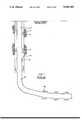
- FIG. 1is a simplified, schematic view of a well bore completion showing the prior art landing nipple which was used to receive a retrievable wireline plug and which presented a restriction in the internal diameter of the tubing string;
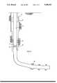
- FIG. 2is a simplified, schematic view similar to FIG. 1 which shows the proposed completion apparatus and method of the invention
- FIGS. 3a and 3bare a side, quarter-sectional view of the well tool of the invention showing the expendable plug which initially closes off the internal bore of the tubing string;
- FIGS. 4a and 4bare simplified, isolated views of alternate arrangements of a pair of strain gages which are used to detect changes in axial and/or circumferential stresses in the tubing string in order to trigger the actuating means of the invention.
- FIG. 1shows a prior art well completion in which a well bore 11 is lined with a 95/8 inch well casing having an internal diameter of approximately 8.535 inches.
- a 7 inch casing, designated as 13, and having an internal diameter of approximately 6.059 inchesis located within the cased well bore and includes a conventional safety valve nipple 15 with an approximate internal diameter of 5.875 inches.
- a commercially available Baker "SAB" packer 17isolates an annular region 19 located below the packer 17 between the casing 13 and the well bore 11.
- a landing nipple 21forms an internal profile within the bore of the casing 13 below the packer 17, thereby reducing the internal diameter to approximately 5.625 inches.
- the completionalso includes a production casing 23 which depends from the outer casing and which follows a deviated bore, as illustrated in FIG. 1 to a producing interval indicated by the perforations 25.
- the internal diameter of the production casing adjacent the perforationsis approximately 6.059 inches.
- FIG. 2illustrates the proposed completion of the invention in which a well bore 27 is lined with a 103/4 inch casing.
- a commercially available Baker "FVLS" tubing mounted valve 29is located within a string of 7 inch casing 31 which has an approximate internal diameter of 6.059 inches.
- a Baker commercially available "SAB" packer 33isolates an annular region 35 located below the packer 33 between the casing 31 and the well bore 27.
- An expendable plug 37 of the inventioninitially closes off flow from the perforated zone 39 up the internal bore of the casing 31 to the well surface.
- the expendable plug 37forms a portion of a well tool having an approximate internal diameter of 6.00 inches which is approximately equal to the minimum internal diameter of the string of pipe forming the flow path to the well surface.
- the terms conduit, pipe, casing and tubingwill all be used interchangeably.
- FIG. 3ashows the preferred expendable plug of the invention, designated generally as 41.
- the plug 41includes a tubular housing 43 having a threaded upper extent 45 which is adapted to be made up in the string of well tubing (47 in FIG. 2) extending to the well surface and having a lower threaded extent 49 which is similarly made up in the downwardly depending string of tubing.
- the tubing string 47has a predetermined minimum internal diameter, in this case approximately 6 inches.
- the internal diameter of the internal bore 53 of the tubular housingis also approximately 6 inches.
- the tubular housing 43includes a plug 51 of an expendable material which initially closes off the internal bore 53 of the tubing string at a selected location, as will be described more fully.
- a hydraulically settable well packer(33 in FIG. 2) is carried about the tubing string extending from the well surface above the well tool 41 and includes passage means such as a control line which communicates with the control line 55 of the well tool 41 for communicating hydraulic pressure to the packer for setting the packer.
- Packersare a well-known conventional devices featuring resilient elements which can be selectively expanded and contracted to contact either a well bore or casing to seal off an annular area.
- a typical exampleis the Baker "SAB" hydro-set production packer illustrated at page 516 of the Baker Packer 1984-1985 Catalog and commercially available from Baker Hughes Incorporated.
- Valve meansare provided within the tubular housing 43 which are selectively moveable between the closed position shown in the FIG. 3a and an open position where flow is possible through the tubing string and through the control line 55 to the packer to set the packer 33 and a closed position where flow is prevented.
- the tubular housingincludes a port 57 which communicates the tubing string internal bore 53 with the control line 55 to the packer 33.
- the valve meansfurther comprises a generally elongated piston member 59 having a first extent 61 which defines a spring bearing surface for retaining a coil spring 63 which acts on the elongate piston member to urge the valve means toward the open position.
- the elongate memberhas a second extent 65 which includes a sealing surface such as the spaced 0-rings 67, 69 shown in FIG. 3a. The sealing surface serves to close the port 57 provided in the tubular housing to the control line 55 of the packer when the valve means is in the closed position shown in FIG. 3a.
- Restraining meanssuch as shear pins 71 are provided for initially holding the valve means in the closed position shown in FIG. 3b.
- a potential energy meansis provided for storing potential energy on the tool.
- the potential energy meansis a pyrotechnic cartridge 73 which, when triggered generates gas pressure which acts on the exterior face 75 of the piston member 59 to force movement of the elongated piston member and sever the shear pins 71. Movement of the elongated piston member moves the valve means to the open position whereby aperture 77 of the valve means is aligned with the port 57 to allow communication of fluid within the internal bore of the tubing string through the control line 55 to set the packer.
- a control meansis preferably provided for selectively releasing the potential energy means upon receipt of a first triggering signal to convert the stored potential energy into kinetic energy, where upon the kinetic energy over powers the restraining means 71 to move the valve means 59 to the open position and allow the packer to be set.
- the control meanscan take a variety of forms including a conventional timer or a signal sensing and processing unit.
- the control means 79preferably includes a signal generating means forming a part of the wall of the tubing string leading to the well surface for selectively generating a signal in response to a predetermined condition detectable on the wall of the tubing string.
- the signal generating meansincludes a pressure transducer 85 which serves to generate a signal to the control means 79 based upon the detected pressure of fluids within the internal bore 53 of the tubing string.
- a strain gage(FIGS. 4a and 4b) is applied to the wall of the tubing string which will change its resistance in response to significant changes in the stresses existing in the conduit wall to which it is attached.
- the strain gage(400 in FIG. 4a) is shown as having connectors 400a, 400b, 400c and 400d respectively connected to the midpoints of each side of the strain gage 400.
- the connectors 400a and 400cwill detect changes in resistance due to changes in axial stress in the conduit.
- Connectors 400b and 400dwill detect changes in resistance due to changes in circumferential stress in the conduit.
- Connectors 400a, 400b, 400c and 400dthus provide signal inputs to a microprocessor (board 80 in FIG. 3) which will generate an activating voltage for operating the downhole tool.
- a microprocessorboard 80 in FIG. 3
- FIG. 4bAnother arrangement of strain gages 401, 402 is shown in FIG. 4b.
- the first strain gage 401has connectors 400a, 400c to indicate axial stresses.
- the second strain gage 402is circumferentially secured to the conduit and has connectors 400b and 400d secured to its opposite ends to indicate circumferential stresses in the conduit.
- the microprocessor 80 included as a part of the control means 79is pre-programmed to detect a predetermined sequence of strain which is detected by the strain gage.
- a battery pack 87delivers electrical energy through the leads 89 to the microprocessor and, through the microprocessor, to the pyrotechnic cartridge 73.
- the strain gagedetects the stresses defined through the tubing string, a signal is sent through leads 91, which actuates the pyrotechnic charge 73.
- gas pressurebuilds up against the exterior face 75 of the piston member 59, shearing the screw 71 and moving the valve means from the closed position shown in FIG. 3a to the open position.
- Actuating meansare also provided which are associated with the plug of expendable material 51 and which are responsive to a second and distinct triggering signal from the control means for expending the expendable material upon receipt of the second and distinct triggering signal.
- the expendable plug 51is a solid, ceramic disc which is molded about an explosive cord 78 for expending the expendable material upon receipt of the second and distinct triggering signal whereby the plug is removed from the internal bore of the tubing string and fluids in the surrounding earthen formation are allowed to flow up the tubing string to the well surface.
- the explosive cord 78can be, for example a "PRIMACORD" of the type used in perforating guns and commercially available from Baker Service Tools of Houston, Tex.
- the explosive cord 78is placed in communication with the control means 79 by means of a suitable lead line 81 and plugs 83, 85.
- the second and distinct signalis thus detected and processed by the control means 79 to cause current to flow through the leads 81 to the explosive cord 78 to expend the plug 51.
- expendable plug 51is shown as a ceramic disc containing an explosive means, it could also be an expendable member which is flowed up or down the internal bore of the tubing string, which is imploded or which is attacked by means of a chemical agent or by chemical reaction.
- a well toolis made up including a plug and run on a tubing string to a selected depth within the well bore.
- the well packer 33is then set to isolate a production interval of the well bore.
- Actuating means, associated with the plug 51are then actuated to dislocate the plug upon receipt of a triggering signal transmitted from the well surface. Dislocating the plug 51 allows the dislocated plug to flow to the well surface as fluids in the surrounding earthen formation are allowed to flow up the tubing string to the well surface.
- the plugis formed of an expendable material and the actuating means associated with the plug serve to expend the material upon receipt of a triggering signal transmitted from the well surface. Since the plug is expended during the actuating step, the predetermined minimum internal diameter of the tubing string is maintained both before and after expending the plug of expendable material.
- the tubing string above the well toolcan be tested for leaks by pressurizing the internal bore of the tubing string with the pressurized fluid pumped down the internal bore of the tubing string from the well surface.
- the expendable plugalso allows the well tool to be run into position within the well bore where the internal bore of the tubing string being initially closed off by the plug. Hydrostatic forces in the tubing string above the well tool can then be removed and, thereafter, the plug can be expended to allow well bore fluids to enter the underbalanced tubing string and flow up the tubing string to the well surface.
- the expendable plug of the inventioncan be provided as a part of a well tool which maintains a predetermined minimum internal diameter of an associated tubing string without constituting a restriction in the tubing string.
- the expendable plugcan be provided in a variety of forms including exploded members, imploded members, members attacked by chemical reaction and members which are flowed up or flowed down the tubing string.
- the device of the inventionallows the operator to test the integrity of the tubing string during running in operations without fear of setting the hydraulic packer prematurely.
- the expendable plugalso allows the operator to create an underbalanced situation above the well tool to facilitate flow of well bore fluids prior to expending the plug.
Landscapes
- Life Sciences & Earth Sciences (AREA)
- Engineering & Computer Science (AREA)
- Geology (AREA)
- Mining & Mineral Resources (AREA)
- Physics & Mathematics (AREA)
- Environmental & Geological Engineering (AREA)
- Fluid Mechanics (AREA)
- General Life Sciences & Earth Sciences (AREA)
- Geochemistry & Mineralogy (AREA)
- Pipe Accessories (AREA)
Abstract
Description
Claims (16)
Priority Applications (2)
| Application Number | Priority Date | Filing Date | Title |
|---|---|---|---|
| US07/695,262US5188183A (en) | 1991-05-03 | 1991-05-03 | Method and apparatus for controlling the flow of well bore fluids |
| GB9209490AGB2255366B (en) | 1991-05-03 | 1992-05-01 | Method and apparatus for controlling the flow of well bore fluids |
Applications Claiming Priority (1)
| Application Number | Priority Date | Filing Date | Title |
|---|---|---|---|
| US07/695,262US5188183A (en) | 1991-05-03 | 1991-05-03 | Method and apparatus for controlling the flow of well bore fluids |
Publications (1)
| Publication Number | Publication Date |
|---|---|
| US5188183Atrue US5188183A (en) | 1993-02-23 |
Family
ID=24792295
Family Applications (1)
| Application Number | Title | Priority Date | Filing Date |
|---|---|---|---|
| US07/695,262Expired - LifetimeUS5188183A (en) | 1991-05-03 | 1991-05-03 | Method and apparatus for controlling the flow of well bore fluids |
Country Status (2)
| Country | Link |
|---|---|
| US (1) | US5188183A (en) |
| GB (1) | GB2255366B (en) |
Cited By (111)
| Publication number | Priority date | Publication date | Assignee | Title |
|---|---|---|---|---|
| US5597042A (en)* | 1995-02-09 | 1997-01-28 | Baker Hughes Incorporated | Method for controlling production wells having permanent downhole formation evaluation sensors |
| US5662165A (en)* | 1995-02-09 | 1997-09-02 | Baker Hughes Incorporated | Production wells having permanent downhole formation evaluation sensors |
| US5706896A (en)* | 1995-02-09 | 1998-01-13 | Baker Hughes Incorporated | Method and apparatus for the remote control and monitoring of production wells |
| US5706892A (en)* | 1995-02-09 | 1998-01-13 | Baker Hughes Incorporated | Downhole tools for production well control |
| US5730219A (en)* | 1995-02-09 | 1998-03-24 | Baker Hughes Incorporated | Production wells having permanent downhole formation evaluation sensors |
| US5732776A (en)* | 1995-02-09 | 1998-03-31 | Baker Hughes Incorporated | Downhole production well control system and method |
| US5765641A (en)* | 1994-05-02 | 1998-06-16 | Halliburton Energy Services, Inc. | Bidirectional disappearing plug |
| US5896924A (en)* | 1997-03-06 | 1999-04-27 | Baker Hughes Incorporated | Computer controlled gas lift system |
| US5947205A (en)* | 1996-06-20 | 1999-09-07 | Halliburton Energy Services, Inc. | Linear indexing apparatus with selective porting |
| US5960883A (en)* | 1995-02-09 | 1999-10-05 | Baker Hughes Incorporated | Power management system for downhole control system in a well and method of using same |
| US6006832A (en)* | 1995-02-09 | 1999-12-28 | Baker Hughes Incorporated | Method and system for monitoring and controlling production and injection wells having permanent downhole formation evaluation sensors |
| US6012015A (en)* | 1995-02-09 | 2000-01-04 | Baker Hughes Incorporated | Control model for production wells |
| WO2000015945A1 (en)* | 1998-09-10 | 2000-03-23 | Camco International, Inc. | Method and apparatus for downhole safety valve remediation |
| WO2000017483A1 (en)* | 1998-09-21 | 2000-03-30 | Schlumberger Technology Corporation | Method and apparatus for relieving pressure |
| US6065538A (en)* | 1995-02-09 | 2000-05-23 | Baker Hughes Corporation | Method of obtaining improved geophysical information about earth formations |
| US6076600A (en)* | 1998-02-27 | 2000-06-20 | Halliburton Energy Services, Inc. | Plug apparatus having a dispersible plug member and a fluid barrier |
| US6119783A (en)* | 1994-05-02 | 2000-09-19 | Halliburton Energy Services, Inc. | Linear indexing apparatus and methods of using same |
| US6220350B1 (en) | 1998-12-01 | 2001-04-24 | Halliburton Energy Services, Inc. | High strength water soluble plug |
| WO2001018357A3 (en)* | 1999-09-07 | 2001-08-02 | Halliburton Energy Serv Inc | Methods and associated apparatus for downhole data retrieval, monitoring and tool actuation |
| US6328109B1 (en) | 1999-11-16 | 2001-12-11 | Schlumberger Technology Corp. | Downhole valve |
| US6349772B2 (en) | 1998-11-02 | 2002-02-26 | Halliburton Energy Services, Inc. | Apparatus and method for hydraulically actuating a downhole device from a remote location |
| US6384738B1 (en) | 1997-04-07 | 2002-05-07 | Halliburton Energy Services, Inc. | Pressure impulse telemetry apparatus and method |
| US6388577B1 (en) | 1997-04-07 | 2002-05-14 | Kenneth J. Carstensen | High impact communication and control system |
| US6442105B1 (en) | 1995-02-09 | 2002-08-27 | Baker Hughes Incorporated | Acoustic transmission system |
| US6597175B1 (en) | 1999-09-07 | 2003-07-22 | Halliburton Energy Services, Inc. | Electromagnetic detector apparatus and method for oil or gas well, and circuit-bearing displaceable object to be detected therein |
| US20030168214A1 (en)* | 2000-04-07 | 2003-09-11 | Odd Sollesnes | Method and device for testing a well |
| US20040221993A1 (en)* | 2003-05-09 | 2004-11-11 | Patterson Michael L. | Method for removing a tool from a well |
| US20040244990A1 (en)* | 2001-08-03 | 2004-12-09 | Wolfgang Herr | In-situ evaporation |
| US20050072575A1 (en)* | 2003-10-01 | 2005-04-07 | Baker Hughes Incorporated | Model HCCV hydrostatic closed circulation valve |
| US20060237191A1 (en)* | 2002-10-02 | 2006-10-26 | Baker Hughes Incorporated | Model HCCV hydrostatic closed circulation valve |
| US20070044958A1 (en)* | 2005-08-31 | 2007-03-01 | Schlumberger Technology Corporation | Well Operating Elements Comprising a Soluble Component and Methods of Use |
| US20070107908A1 (en)* | 2005-11-16 | 2007-05-17 | Schlumberger Technology Corporation | Oilfield Elements Having Controlled Solubility and Methods of Use |
| US20070181224A1 (en)* | 2006-02-09 | 2007-08-09 | Schlumberger Technology Corporation | Degradable Compositions, Apparatus Comprising Same, and Method of Use |
| US20080017379A1 (en)* | 2006-07-20 | 2008-01-24 | Halliburton Energy Services, Inc. | Method for removing a sealing plug from a well |
| US20080257549A1 (en)* | 2006-06-08 | 2008-10-23 | Halliburton Energy Services, Inc. | Consumable Downhole Tools |
| US20100101803A1 (en)* | 2007-02-22 | 2010-04-29 | Halliburton Energy Services, Inc. | Consumable Downhole Tools |
| US20100163222A1 (en)* | 2007-04-17 | 2010-07-01 | Viggo Brandsdal | Device for a test plug |
| US20100175867A1 (en)* | 2009-01-14 | 2010-07-15 | Halliburton Energy Services, Inc. | Well Tools Incorporating Valves Operable by Low Electrical Power Input |
| US20100209288A1 (en)* | 2009-02-16 | 2010-08-19 | Schlumberger Technology Corporation | Aged-hardenable aluminum alloy with environmental degradability, methods of use and making |
| US20110048743A1 (en)* | 2004-05-28 | 2011-03-03 | Schlumberger Technology Corporation | Dissolvable bridge plug |
| US20110132612A1 (en)* | 2009-12-08 | 2011-06-09 | Baker Hughes Incorporated | Telescopic Unit with Dissolvable Barrier |
| US20110174504A1 (en)* | 2010-01-15 | 2011-07-21 | Halliburton Energy Services, Inc. | Well tools operable via thermal expansion resulting from reactive materials |
| US20110214881A1 (en)* | 2010-03-05 | 2011-09-08 | Baker Hughes Incorporated | Flow control arrangement and method |
| US8220554B2 (en) | 2006-02-09 | 2012-07-17 | Schlumberger Technology Corporation | Degradable whipstock apparatus and method of use |
| US20120211221A1 (en)* | 2011-02-17 | 2012-08-23 | Baker Hughes Incorporated | Annulus Mounted Potential Energy Driven Setting Tool |
| US8272446B2 (en) | 2006-06-08 | 2012-09-25 | Halliburton Energy Services Inc. | Method for removing a consumable downhole tool |
| US8327931B2 (en) | 2009-12-08 | 2012-12-11 | Baker Hughes Incorporated | Multi-component disappearing tripping ball and method for making the same |
| US8425651B2 (en) | 2010-07-30 | 2013-04-23 | Baker Hughes Incorporated | Nanomatrix metal composite |
| US8573295B2 (en) | 2010-11-16 | 2013-11-05 | Baker Hughes Incorporated | Plug and method of unplugging a seat |
| US8631876B2 (en) | 2011-04-28 | 2014-01-21 | Baker Hughes Incorporated | Method of making and using a functionally gradient composite tool |
| US8776884B2 (en) | 2010-08-09 | 2014-07-15 | Baker Hughes Incorporated | Formation treatment system and method |
| US8783365B2 (en) | 2011-07-28 | 2014-07-22 | Baker Hughes Incorporated | Selective hydraulic fracturing tool and method thereof |
| US8973657B2 (en) | 2010-12-07 | 2015-03-10 | Halliburton Energy Services, Inc. | Gas generator for pressurizing downhole samples |
| US9022107B2 (en) | 2009-12-08 | 2015-05-05 | Baker Hughes Incorporated | Dissolvable tool |
| US9033055B2 (en) | 2011-08-17 | 2015-05-19 | Baker Hughes Incorporated | Selectively degradable passage restriction and method |
| US9057242B2 (en) | 2011-08-05 | 2015-06-16 | Baker Hughes Incorporated | Method of controlling corrosion rate in downhole article, and downhole article having controlled corrosion rate |
| US9068428B2 (en) | 2012-02-13 | 2015-06-30 | Baker Hughes Incorporated | Selectively corrodible downhole article and method of use |
| US9079246B2 (en) | 2009-12-08 | 2015-07-14 | Baker Hughes Incorporated | Method of making a nanomatrix powder metal compact |
| US9080098B2 (en) | 2011-04-28 | 2015-07-14 | Baker Hughes Incorporated | Functionally gradient composite article |
| US9090956B2 (en) | 2011-08-30 | 2015-07-28 | Baker Hughes Incorporated | Aluminum alloy powder metal compact |
| US9090955B2 (en) | 2010-10-27 | 2015-07-28 | Baker Hughes Incorporated | Nanomatrix powder metal composite |
| US9101978B2 (en) | 2002-12-08 | 2015-08-11 | Baker Hughes Incorporated | Nanomatrix powder metal compact |
| US9109429B2 (en) | 2002-12-08 | 2015-08-18 | Baker Hughes Incorporated | Engineered powder compact composite material |
| US9109269B2 (en) | 2011-08-30 | 2015-08-18 | Baker Hughes Incorporated | Magnesium alloy powder metal compact |
| US9127515B2 (en) | 2010-10-27 | 2015-09-08 | Baker Hughes Incorporated | Nanomatrix carbon composite |
| US9133695B2 (en) | 2011-09-03 | 2015-09-15 | Baker Hughes Incorporated | Degradable shaped charge and perforating gun system |
| US9139928B2 (en) | 2011-06-17 | 2015-09-22 | Baker Hughes Incorporated | Corrodible downhole article and method of removing the article from downhole environment |
| US9169705B2 (en) | 2012-10-25 | 2015-10-27 | Halliburton Energy Services, Inc. | Pressure relief-assisted packer |
| US9187990B2 (en) | 2011-09-03 | 2015-11-17 | Baker Hughes Incorporated | Method of using a degradable shaped charge and perforating gun system |
| WO2015175128A1 (en)* | 2014-05-14 | 2015-11-19 | Baker Hughes Incorporated | Apparatus and method for operating a device in a wellbore using signals generated in response to strain on a downhole member |
| US9227243B2 (en) | 2009-12-08 | 2016-01-05 | Baker Hughes Incorporated | Method of making a powder metal compact |
| US9243475B2 (en) | 2009-12-08 | 2016-01-26 | Baker Hughes Incorporated | Extruded powder metal compact |
| US9267347B2 (en) | 2009-12-08 | 2016-02-23 | Baker Huges Incorporated | Dissolvable tool |
| US9284812B2 (en) | 2011-11-21 | 2016-03-15 | Baker Hughes Incorporated | System for increasing swelling efficiency |
| US9284817B2 (en) | 2013-03-14 | 2016-03-15 | Halliburton Energy Services, Inc. | Dual magnetic sensor actuation assembly |
| US9347119B2 (en) | 2011-09-03 | 2016-05-24 | Baker Hughes Incorporated | Degradable high shock impedance material |
| US9366134B2 (en) | 2013-03-12 | 2016-06-14 | Halliburton Energy Services, Inc. | Wellbore servicing tools, systems and methods utilizing near-field communication |
| USRE46137E1 (en) | 2011-07-29 | 2016-09-06 | Baker Hughes Incorporated | Pressure actuated ported sub for subterranean cement completions |
| US9587486B2 (en) | 2013-02-28 | 2017-03-07 | Halliburton Energy Services, Inc. | Method and apparatus for magnetic pulse signature actuation |
| US9605508B2 (en) | 2012-05-08 | 2017-03-28 | Baker Hughes Incorporated | Disintegrable and conformable metallic seal, and method of making the same |
| US9624750B2 (en) | 2009-04-17 | 2017-04-18 | Exxonmobil Upstream Research Company | Systems and methods of diverting fluids in a wellbore using destructible plugs |
| US9643250B2 (en) | 2011-07-29 | 2017-05-09 | Baker Hughes Incorporated | Method of controlling the corrosion rate of alloy particles, alloy particle with controlled corrosion rate, and articles comprising the particle |
| US9643144B2 (en) | 2011-09-02 | 2017-05-09 | Baker Hughes Incorporated | Method to generate and disperse nanostructures in a composite material |
| US9682425B2 (en) | 2009-12-08 | 2017-06-20 | Baker Hughes Incorporated | Coated metallic powder and method of making the same |
| US9707739B2 (en) | 2011-07-22 | 2017-07-18 | Baker Hughes Incorporated | Intermetallic metallic composite, method of manufacture thereof and articles comprising the same |
| US9752414B2 (en) | 2013-05-31 | 2017-09-05 | Halliburton Energy Services, Inc. | Wellbore servicing tools, systems and methods utilizing downhole wireless switches |
| US9789544B2 (en) | 2006-02-09 | 2017-10-17 | Schlumberger Technology Corporation | Methods of manufacturing oilfield degradable alloys and related products |
| US9816339B2 (en) | 2013-09-03 | 2017-11-14 | Baker Hughes, A Ge Company, Llc | Plug reception assembly and method of reducing restriction in a borehole |
| US9833838B2 (en) | 2011-07-29 | 2017-12-05 | Baker Hughes, A Ge Company, Llc | Method of controlling the corrosion rate of alloy particles, alloy particle with controlled corrosion rate, and articles comprising the particle |
| US9850725B2 (en) | 2015-04-15 | 2017-12-26 | Baker Hughes, A Ge Company, Llc | One trip interventionless liner hanger and packer setting apparatus and method |
| US9856547B2 (en) | 2011-08-30 | 2018-01-02 | Bakers Hughes, A Ge Company, Llc | Nanostructured powder metal compact |
| US9890604B2 (en) | 2014-04-04 | 2018-02-13 | Owen Oil Tools Lp | Devices and related methods for actuating wellbore tools with a pressurized gas |
| US9910026B2 (en) | 2015-01-21 | 2018-03-06 | Baker Hughes, A Ge Company, Llc | High temperature tracers for downhole detection of produced water |
| US9926766B2 (en) | 2012-01-25 | 2018-03-27 | Baker Hughes, A Ge Company, Llc | Seat for a tubular treating system |
| US10016810B2 (en) | 2015-12-14 | 2018-07-10 | Baker Hughes, A Ge Company, Llc | Methods of manufacturing degradable tools using a galvanic carrier and tools manufactured thereof |
| US10125560B2 (en) | 2012-11-27 | 2018-11-13 | Halliburton Energy Services, Inc. | Wellbore bailer |
| US20190010773A1 (en)* | 2017-07-05 | 2019-01-10 | Baker Hughes, A Ge Company, Llc | Potential Energy Actuated Valve Triggered by Collapse of a Support Member |
| US10221637B2 (en) | 2015-08-11 | 2019-03-05 | Baker Hughes, A Ge Company, Llc | Methods of manufacturing dissolvable tools via liquid-solid state molding |
| US10240419B2 (en) | 2009-12-08 | 2019-03-26 | Baker Hughes, A Ge Company, Llc | Downhole flow inhibition tool and method of unplugging a seat |
| US10378303B2 (en) | 2015-03-05 | 2019-08-13 | Baker Hughes, A Ge Company, Llc | Downhole tool and method of forming the same |
| US10808523B2 (en) | 2014-11-25 | 2020-10-20 | Halliburton Energy Services, Inc. | Wireless activation of wellbore tools |
| US10907471B2 (en) | 2013-05-31 | 2021-02-02 | Halliburton Energy Services, Inc. | Wireless activation of wellbore tools |
| CN112647882A (en)* | 2019-10-11 | 2021-04-13 | 中国石油化工股份有限公司 | Pipe column and method for unsealing through micro-explosion |
| US11167343B2 (en) | 2014-02-21 | 2021-11-09 | Terves, Llc | Galvanically-active in situ formed particles for controlled rate dissolving tools |
| US11365164B2 (en) | 2014-02-21 | 2022-06-21 | Terves, Llc | Fluid activated disintegrating metal system |
| US20230117471A1 (en)* | 2021-10-18 | 2023-04-20 | Saudi Arabian Oil Company | Wellbore sampling and testing system |
| US11649526B2 (en) | 2017-07-27 | 2023-05-16 | Terves, Llc | Degradable metal matrix composite |
| US11774002B2 (en) | 2020-04-17 | 2023-10-03 | Schlumberger Technology Corporation | Hydraulic trigger with locked spring force |
| US12000241B2 (en) | 2020-02-18 | 2024-06-04 | Schlumberger Technology Corporation | Electronic rupture disc with atmospheric chamber |
| US12018356B2 (en) | 2014-04-18 | 2024-06-25 | Terves Inc. | Galvanically-active in situ formed particles for controlled rate dissolving tools |
| US12025238B2 (en) | 2020-02-18 | 2024-07-02 | Schlumberger Technology Corporation | Hydraulic trigger for isolation valves |
Families Citing this family (1)
| Publication number | Priority date | Publication date | Assignee | Title |
|---|---|---|---|---|
| NO311626B1 (en)* | 1994-08-26 | 2001-12-17 | Halliburton Co | Torsion-resistant well packing device, and method of installing it |
Citations (6)
| Publication number | Priority date | Publication date | Assignee | Title |
|---|---|---|---|---|
| US3095040A (en)* | 1961-06-30 | 1963-06-25 | Bramlett Oil Field Service Inc | Access valve for completing oil wells |
| US3357504A (en)* | 1965-06-07 | 1967-12-12 | Gerald G Calhoun | Straddle packer wire line tester |
| US3980134A (en)* | 1973-12-26 | 1976-09-14 | Otis Engineering Corporation | Well packer with frangible closure |
| US4220206A (en)* | 1979-01-22 | 1980-09-02 | Winkle Denzal W Van | Quick opening closure arrangement for well completions |
| US4678037A (en)* | 1985-12-06 | 1987-07-07 | Amoco Corporation | Method and apparatus for completing a plurality of zones in a wellbore |
| US4896722A (en)* | 1988-05-26 | 1990-01-30 | Schlumberger Technology Corporation | Multiple well tool control systems in a multi-valve well testing system having automatic control modes |
Family Cites Families (2)
| Publication number | Priority date | Publication date | Assignee | Title |
|---|---|---|---|---|
| US4188999A (en)* | 1978-09-27 | 1980-02-19 | Baker International Corporation | Expendable plug and packer assembly |
| US4469173A (en)* | 1983-05-09 | 1984-09-04 | Hughes Tool Company | Expendable plug assembly |
- 1991
- 1991-05-03USUS07/695,262patent/US5188183A/ennot_activeExpired - Lifetime
- 1992
- 1992-05-01GBGB9209490Apatent/GB2255366B/ennot_activeExpired - Lifetime
Patent Citations (6)
| Publication number | Priority date | Publication date | Assignee | Title |
|---|---|---|---|---|
| US3095040A (en)* | 1961-06-30 | 1963-06-25 | Bramlett Oil Field Service Inc | Access valve for completing oil wells |
| US3357504A (en)* | 1965-06-07 | 1967-12-12 | Gerald G Calhoun | Straddle packer wire line tester |
| US3980134A (en)* | 1973-12-26 | 1976-09-14 | Otis Engineering Corporation | Well packer with frangible closure |
| US4220206A (en)* | 1979-01-22 | 1980-09-02 | Winkle Denzal W Van | Quick opening closure arrangement for well completions |
| US4678037A (en)* | 1985-12-06 | 1987-07-07 | Amoco Corporation | Method and apparatus for completing a plurality of zones in a wellbore |
| US4896722A (en)* | 1988-05-26 | 1990-01-30 | Schlumberger Technology Corporation | Multiple well tool control systems in a multi-valve well testing system having automatic control modes |
Cited By (193)
| Publication number | Priority date | Publication date | Assignee | Title |
|---|---|---|---|---|
| US5765641A (en)* | 1994-05-02 | 1998-06-16 | Halliburton Energy Services, Inc. | Bidirectional disappearing plug |
| US6119783A (en)* | 1994-05-02 | 2000-09-19 | Halliburton Energy Services, Inc. | Linear indexing apparatus and methods of using same |
| US6209640B1 (en) | 1995-02-09 | 2001-04-03 | Baker Hughes Incorporated | Method of obtaining improved geophysical information about earth formations |
| US5975204A (en)* | 1995-02-09 | 1999-11-02 | Baker Hughes Incorporated | Method and apparatus for the remote control and monitoring of production wells |
| US5730219A (en)* | 1995-02-09 | 1998-03-24 | Baker Hughes Incorporated | Production wells having permanent downhole formation evaluation sensors |
| US5732776A (en)* | 1995-02-09 | 1998-03-31 | Baker Hughes Incorporated | Downhole production well control system and method |
| US5706896A (en)* | 1995-02-09 | 1998-01-13 | Baker Hughes Incorporated | Method and apparatus for the remote control and monitoring of production wells |
| US5803167A (en)* | 1995-02-09 | 1998-09-08 | Baker Hughes Incorporated | Computer controlled downhole tools for production well control |
| US5868201A (en)* | 1995-02-09 | 1999-02-09 | Baker Hughes Incorporated | Computer controlled downhole tools for production well control |
| US5597042A (en)* | 1995-02-09 | 1997-01-28 | Baker Hughes Incorporated | Method for controlling production wells having permanent downhole formation evaluation sensors |
| US5937945A (en)* | 1995-02-09 | 1999-08-17 | Baker Hughes Incorporated | Computer controlled gas lift system |
| US5941307A (en)* | 1995-02-09 | 1999-08-24 | Baker Hughes Incorporated | Production well telemetry system and method |
| US6464011B2 (en) | 1995-02-09 | 2002-10-15 | Baker Hughes Incorporated | Production well telemetry system and method |
| US5960883A (en)* | 1995-02-09 | 1999-10-05 | Baker Hughes Incorporated | Power management system for downhole control system in a well and method of using same |
| US6253848B1 (en) | 1995-02-09 | 2001-07-03 | Baker Hughes Incorporated | Method of obtaining improved geophysical information about earth formations |
| US6006832A (en)* | 1995-02-09 | 1999-12-28 | Baker Hughes Incorporated | Method and system for monitoring and controlling production and injection wells having permanent downhole formation evaluation sensors |
| US6012015A (en)* | 1995-02-09 | 2000-01-04 | Baker Hughes Incorporated | Control model for production wells |
| US6442105B1 (en) | 1995-02-09 | 2002-08-27 | Baker Hughes Incorporated | Acoustic transmission system |
| US6302204B1 (en) | 1995-02-09 | 2001-10-16 | Baker Hughes Incorporated | Method of obtaining improved geophysical information about earth formations |
| US6065538A (en)* | 1995-02-09 | 2000-05-23 | Baker Hughes Corporation | Method of obtaining improved geophysical information about earth formations |
| US5706892A (en)* | 1995-02-09 | 1998-01-13 | Baker Hughes Incorporated | Downhole tools for production well control |
| US5662165A (en)* | 1995-02-09 | 1997-09-02 | Baker Hughes Incorporated | Production wells having permanent downhole formation evaluation sensors |
| US6192980B1 (en)* | 1995-02-09 | 2001-02-27 | Baker Hughes Incorporated | Method and apparatus for the remote control and monitoring of production wells |
| US6176312B1 (en) | 1995-02-09 | 2001-01-23 | Baker Hughes Incorporated | Method and apparatus for the remote control and monitoring of production wells |
| US6192988B1 (en) | 1995-02-09 | 2001-02-27 | Baker Hughes Incorporated | Production well telemetry system and method |
| EP0775803A3 (en)* | 1995-11-22 | 2001-10-17 | Halliburton Company | Linear indexing apparatus and methods of using same |
| EP0775804A3 (en)* | 1995-11-22 | 2001-10-17 | Halliburton Company | Completely removable bidirectional plug |
| US5947205A (en)* | 1996-06-20 | 1999-09-07 | Halliburton Energy Services, Inc. | Linear indexing apparatus with selective porting |
| US5896924A (en)* | 1997-03-06 | 1999-04-27 | Baker Hughes Incorporated | Computer controlled gas lift system |
| US7295491B2 (en) | 1997-04-07 | 2007-11-13 | Carstensen Kenneth J | High impact communication and control system |
| US6760275B2 (en) | 1997-04-07 | 2004-07-06 | Kenneth J. Carstensen | High impact communication and control system |
| US6388577B1 (en) | 1997-04-07 | 2002-05-14 | Kenneth J. Carstensen | High impact communication and control system |
| US20040238184A1 (en)* | 1997-04-07 | 2004-12-02 | Carstensen Kenneth J. | High impact communication and control system |
| US6384738B1 (en) | 1997-04-07 | 2002-05-07 | Halliburton Energy Services, Inc. | Pressure impulse telemetry apparatus and method |
| US6076600A (en)* | 1998-02-27 | 2000-06-20 | Halliburton Energy Services, Inc. | Plug apparatus having a dispersible plug member and a fluid barrier |
| AU739629B2 (en)* | 1998-02-27 | 2001-10-18 | Halliburton Energy Services, Inc. | Plug apparatus having a dispersible plug member and a fluid barrier |
| EP0939194A3 (en)* | 1998-02-27 | 2000-12-13 | Halliburton Energy Services, Inc. | Plug device for use in a subterranean well |
| US6273187B1 (en) | 1998-09-10 | 2001-08-14 | Schlumberger Technology Corporation | Method and apparatus for downhole safety valve remediation |
| WO2000015945A1 (en)* | 1998-09-10 | 2000-03-23 | Camco International, Inc. | Method and apparatus for downhole safety valve remediation |
| US6293346B1 (en) | 1998-09-21 | 2001-09-25 | Schlumberger Technology Corporation | Method and apparatus for relieving pressure |
| GB2358656A (en)* | 1998-09-21 | 2001-08-01 | Schlumberger Technology Corp | Method and apparatus for relieving pressure |
| WO2000017483A1 (en)* | 1998-09-21 | 2000-03-30 | Schlumberger Technology Corporation | Method and apparatus for relieving pressure |
| GB2358656B (en)* | 1998-09-21 | 2003-03-12 | Schlumberger Technology Corp | Method and apparatus for relieving pressure |
| US6349772B2 (en) | 1998-11-02 | 2002-02-26 | Halliburton Energy Services, Inc. | Apparatus and method for hydraulically actuating a downhole device from a remote location |
| US6220350B1 (en) | 1998-12-01 | 2001-04-24 | Halliburton Energy Services, Inc. | High strength water soluble plug |
| US6359569B2 (en) | 1999-09-07 | 2002-03-19 | Halliburton Energy Services, Inc. | Methods and associated apparatus for downhole data retrieval, monitoring and tool actuation |
| US6497280B2 (en) | 1999-09-07 | 2002-12-24 | Halliburton Energy Services, Inc. | Methods and associated apparatus for downhole data retrieval, monitoring and tool actuation |
| US6343649B1 (en) | 1999-09-07 | 2002-02-05 | Halliburton Energy Services, Inc. | Methods and associated apparatus for downhole data retrieval, monitoring and tool actuation |
| US6588505B2 (en) | 1999-09-07 | 2003-07-08 | Halliburton Energy Services, Inc. | Methods and associated apparatus for downhole data retrieval, monitoring and tool actuation |
| US6597175B1 (en) | 1999-09-07 | 2003-07-22 | Halliburton Energy Services, Inc. | Electromagnetic detector apparatus and method for oil or gas well, and circuit-bearing displaceable object to be detected therein |
| WO2001018357A3 (en)* | 1999-09-07 | 2001-08-02 | Halliburton Energy Serv Inc | Methods and associated apparatus for downhole data retrieval, monitoring and tool actuation |
| US6481505B2 (en) | 1999-09-07 | 2002-11-19 | Halliburton Energy Services, Inc. | Methods and associated apparatus for downhole data retrieval, monitoring and tool actuation |
| US6328109B1 (en) | 1999-11-16 | 2001-12-11 | Schlumberger Technology Corp. | Downhole valve |
| US20030168214A1 (en)* | 2000-04-07 | 2003-09-11 | Odd Sollesnes | Method and device for testing a well |
| US20040244990A1 (en)* | 2001-08-03 | 2004-12-09 | Wolfgang Herr | In-situ evaporation |
| US7117946B2 (en)* | 2001-08-03 | 2006-10-10 | Wolfgang Herr | In-situ evaporation |
| US7464758B2 (en) | 2002-10-02 | 2008-12-16 | Baker Hughes Incorporated | Model HCCV hydrostatic closed circulation valve |
| US20060237191A1 (en)* | 2002-10-02 | 2006-10-26 | Baker Hughes Incorporated | Model HCCV hydrostatic closed circulation valve |
| US9109429B2 (en) | 2002-12-08 | 2015-08-18 | Baker Hughes Incorporated | Engineered powder compact composite material |
| US9101978B2 (en) | 2002-12-08 | 2015-08-11 | Baker Hughes Incorporated | Nanomatrix powder metal compact |
| US6926086B2 (en)* | 2003-05-09 | 2005-08-09 | Halliburton Energy Services, Inc. | Method for removing a tool from a well |
| US20060021748A1 (en)* | 2003-05-09 | 2006-02-02 | Swor Loren C | Sealing plug and method for removing same from a well |
| US7328750B2 (en) | 2003-05-09 | 2008-02-12 | Halliburton Energy Services, Inc. | Sealing plug and method for removing same from a well |
| US20040221993A1 (en)* | 2003-05-09 | 2004-11-11 | Patterson Michael L. | Method for removing a tool from a well |
| US20050072575A1 (en)* | 2003-10-01 | 2005-04-07 | Baker Hughes Incorporated | Model HCCV hydrostatic closed circulation valve |
| US7063152B2 (en) | 2003-10-01 | 2006-06-20 | Baker Hughes Incorporated | Model HCCV hydrostatic closed circulation valve |
| US10316616B2 (en) | 2004-05-28 | 2019-06-11 | Schlumberger Technology Corporation | Dissolvable bridge plug |
| US20110048743A1 (en)* | 2004-05-28 | 2011-03-03 | Schlumberger Technology Corporation | Dissolvable bridge plug |
| US9982505B2 (en) | 2005-08-31 | 2018-05-29 | Schlumberger Technology Corporation | Well operating elements comprising a soluble component and methods of use |
| US8567494B2 (en) | 2005-08-31 | 2013-10-29 | Schlumberger Technology Corporation | Well operating elements comprising a soluble component and methods of use |
| US20070044958A1 (en)* | 2005-08-31 | 2007-03-01 | Schlumberger Technology Corporation | Well Operating Elements Comprising a Soluble Component and Methods of Use |
| US20070107908A1 (en)* | 2005-11-16 | 2007-05-17 | Schlumberger Technology Corporation | Oilfield Elements Having Controlled Solubility and Methods of Use |
| US8231947B2 (en) | 2005-11-16 | 2012-07-31 | Schlumberger Technology Corporation | Oilfield elements having controlled solubility and methods of use |
| US8211247B2 (en) | 2006-02-09 | 2012-07-03 | Schlumberger Technology Corporation | Degradable compositions, apparatus comprising same, and method of use |
| US20070181224A1 (en)* | 2006-02-09 | 2007-08-09 | Schlumberger Technology Corporation | Degradable Compositions, Apparatus Comprising Same, and Method of Use |
| US9789544B2 (en) | 2006-02-09 | 2017-10-17 | Schlumberger Technology Corporation | Methods of manufacturing oilfield degradable alloys and related products |
| US8220554B2 (en) | 2006-02-09 | 2012-07-17 | Schlumberger Technology Corporation | Degradable whipstock apparatus and method of use |
| US20080257549A1 (en)* | 2006-06-08 | 2008-10-23 | Halliburton Energy Services, Inc. | Consumable Downhole Tools |
| US8291970B2 (en) | 2006-06-08 | 2012-10-23 | Halliburton Energy Services Inc. | Consumable downhole tools |
| US8272446B2 (en) | 2006-06-08 | 2012-09-25 | Halliburton Energy Services Inc. | Method for removing a consumable downhole tool |
| US8256521B2 (en) | 2006-06-08 | 2012-09-04 | Halliburton Energy Services Inc. | Consumable downhole tools |
| US20080017379A1 (en)* | 2006-07-20 | 2008-01-24 | Halliburton Energy Services, Inc. | Method for removing a sealing plug from a well |
| US7591318B2 (en) | 2006-07-20 | 2009-09-22 | Halliburton Energy Services, Inc. | Method for removing a sealing plug from a well |
| US8056638B2 (en) | 2007-02-22 | 2011-11-15 | Halliburton Energy Services Inc. | Consumable downhole tools |
| US20100101803A1 (en)* | 2007-02-22 | 2010-04-29 | Halliburton Energy Services, Inc. | Consumable Downhole Tools |
| US8322449B2 (en) | 2007-02-22 | 2012-12-04 | Halliburton Energy Services, Inc. | Consumable downhole tools |
| US20100163222A1 (en)* | 2007-04-17 | 2010-07-01 | Viggo Brandsdal | Device for a test plug |
| US8397813B2 (en)* | 2007-04-17 | 2013-03-19 | Tco As | Device for a test plug |
| US8235103B2 (en) | 2009-01-14 | 2012-08-07 | Halliburton Energy Services, Inc. | Well tools incorporating valves operable by low electrical power input |
| US20100175867A1 (en)* | 2009-01-14 | 2010-07-15 | Halliburton Energy Services, Inc. | Well Tools Incorporating Valves Operable by Low Electrical Power Input |
| US9593546B2 (en) | 2009-01-14 | 2017-03-14 | Halliburton Energy Services, Inc. | Well tools incorporating valves operable by low electrical power input |
| US8211248B2 (en) | 2009-02-16 | 2012-07-03 | Schlumberger Technology Corporation | Aged-hardenable aluminum alloy with environmental degradability, methods of use and making |
| US20100209288A1 (en)* | 2009-02-16 | 2010-08-19 | Schlumberger Technology Corporation | Aged-hardenable aluminum alloy with environmental degradability, methods of use and making |
| US9624750B2 (en) | 2009-04-17 | 2017-04-18 | Exxonmobil Upstream Research Company | Systems and methods of diverting fluids in a wellbore using destructible plugs |
| US9682425B2 (en) | 2009-12-08 | 2017-06-20 | Baker Hughes Incorporated | Coated metallic powder and method of making the same |
| US9267347B2 (en) | 2009-12-08 | 2016-02-23 | Baker Huges Incorporated | Dissolvable tool |
| US8714268B2 (en) | 2009-12-08 | 2014-05-06 | Baker Hughes Incorporated | Method of making and using multi-component disappearing tripping ball |
| US20110132612A1 (en)* | 2009-12-08 | 2011-06-09 | Baker Hughes Incorporated | Telescopic Unit with Dissolvable Barrier |
| US9227243B2 (en) | 2009-12-08 | 2016-01-05 | Baker Hughes Incorporated | Method of making a powder metal compact |
| US8327931B2 (en) | 2009-12-08 | 2012-12-11 | Baker Hughes Incorporated | Multi-component disappearing tripping ball and method for making the same |
| US9243475B2 (en) | 2009-12-08 | 2016-01-26 | Baker Hughes Incorporated | Extruded powder metal compact |
| US10669797B2 (en) | 2009-12-08 | 2020-06-02 | Baker Hughes, A Ge Company, Llc | Tool configured to dissolve in a selected subsurface environment |
| US9022107B2 (en) | 2009-12-08 | 2015-05-05 | Baker Hughes Incorporated | Dissolvable tool |
| US9079246B2 (en) | 2009-12-08 | 2015-07-14 | Baker Hughes Incorporated | Method of making a nanomatrix powder metal compact |
| US10240419B2 (en) | 2009-12-08 | 2019-03-26 | Baker Hughes, A Ge Company, Llc | Downhole flow inhibition tool and method of unplugging a seat |
| US20110174504A1 (en)* | 2010-01-15 | 2011-07-21 | Halliburton Energy Services, Inc. | Well tools operable via thermal expansion resulting from reactive materials |
| US8839871B2 (en) | 2010-01-15 | 2014-09-23 | Halliburton Energy Services, Inc. | Well tools operable via thermal expansion resulting from reactive materials |
| US20110214881A1 (en)* | 2010-03-05 | 2011-09-08 | Baker Hughes Incorporated | Flow control arrangement and method |
| US8424610B2 (en) | 2010-03-05 | 2013-04-23 | Baker Hughes Incorporated | Flow control arrangement and method |
| US8425651B2 (en) | 2010-07-30 | 2013-04-23 | Baker Hughes Incorporated | Nanomatrix metal composite |
| US8776884B2 (en) | 2010-08-09 | 2014-07-15 | Baker Hughes Incorporated | Formation treatment system and method |
| US9127515B2 (en) | 2010-10-27 | 2015-09-08 | Baker Hughes Incorporated | Nanomatrix carbon composite |
| US9090955B2 (en) | 2010-10-27 | 2015-07-28 | Baker Hughes Incorporated | Nanomatrix powder metal composite |
| US8573295B2 (en) | 2010-11-16 | 2013-11-05 | Baker Hughes Incorporated | Plug and method of unplugging a seat |
| US8973657B2 (en) | 2010-12-07 | 2015-03-10 | Halliburton Energy Services, Inc. | Gas generator for pressurizing downhole samples |
| US20120211221A1 (en)* | 2011-02-17 | 2012-08-23 | Baker Hughes Incorporated | Annulus Mounted Potential Energy Driven Setting Tool |
| US9488028B2 (en) | 2011-02-17 | 2016-11-08 | Baker Hughes Incorporated | Annulus mounted potential energy driven setting tool |
| US8813857B2 (en)* | 2011-02-17 | 2014-08-26 | Baker Hughes Incorporated | Annulus mounted potential energy driven setting tool |
| US10335858B2 (en) | 2011-04-28 | 2019-07-02 | Baker Hughes, A Ge Company, Llc | Method of making and using a functionally gradient composite tool |
| US8631876B2 (en) | 2011-04-28 | 2014-01-21 | Baker Hughes Incorporated | Method of making and using a functionally gradient composite tool |
| US9080098B2 (en) | 2011-04-28 | 2015-07-14 | Baker Hughes Incorporated | Functionally gradient composite article |
| US9631138B2 (en) | 2011-04-28 | 2017-04-25 | Baker Hughes Incorporated | Functionally gradient composite article |
| US9139928B2 (en) | 2011-06-17 | 2015-09-22 | Baker Hughes Incorporated | Corrodible downhole article and method of removing the article from downhole environment |
| US9926763B2 (en) | 2011-06-17 | 2018-03-27 | Baker Hughes, A Ge Company, Llc | Corrodible downhole article and method of removing the article from downhole environment |
| US9707739B2 (en) | 2011-07-22 | 2017-07-18 | Baker Hughes Incorporated | Intermetallic metallic composite, method of manufacture thereof and articles comprising the same |
| US10697266B2 (en) | 2011-07-22 | 2020-06-30 | Baker Hughes, A Ge Company, Llc | Intermetallic metallic composite, method of manufacture thereof and articles comprising the same |
| US8783365B2 (en) | 2011-07-28 | 2014-07-22 | Baker Hughes Incorporated | Selective hydraulic fracturing tool and method thereof |
| US9833838B2 (en) | 2011-07-29 | 2017-12-05 | Baker Hughes, A Ge Company, Llc | Method of controlling the corrosion rate of alloy particles, alloy particle with controlled corrosion rate, and articles comprising the particle |
| USRE46137E1 (en) | 2011-07-29 | 2016-09-06 | Baker Hughes Incorporated | Pressure actuated ported sub for subterranean cement completions |
| US9643250B2 (en) | 2011-07-29 | 2017-05-09 | Baker Hughes Incorporated | Method of controlling the corrosion rate of alloy particles, alloy particle with controlled corrosion rate, and articles comprising the particle |
| US10092953B2 (en) | 2011-07-29 | 2018-10-09 | Baker Hughes, A Ge Company, Llc | Method of controlling the corrosion rate of alloy particles, alloy particle with controlled corrosion rate, and articles comprising the particle |
| US9057242B2 (en) | 2011-08-05 | 2015-06-16 | Baker Hughes Incorporated | Method of controlling corrosion rate in downhole article, and downhole article having controlled corrosion rate |
| US9033055B2 (en) | 2011-08-17 | 2015-05-19 | Baker Hughes Incorporated | Selectively degradable passage restriction and method |
| US10301909B2 (en) | 2011-08-17 | 2019-05-28 | Baker Hughes, A Ge Company, Llc | Selectively degradable passage restriction |
| US10737321B2 (en) | 2011-08-30 | 2020-08-11 | Baker Hughes, A Ge Company, Llc | Magnesium alloy powder metal compact |
| US11090719B2 (en) | 2011-08-30 | 2021-08-17 | Baker Hughes, A Ge Company, Llc | Aluminum alloy powder metal compact |
| US9925589B2 (en) | 2011-08-30 | 2018-03-27 | Baker Hughes, A Ge Company, Llc | Aluminum alloy powder metal compact |
| US9109269B2 (en) | 2011-08-30 | 2015-08-18 | Baker Hughes Incorporated | Magnesium alloy powder metal compact |
| US9856547B2 (en) | 2011-08-30 | 2018-01-02 | Bakers Hughes, A Ge Company, Llc | Nanostructured powder metal compact |
| US9802250B2 (en) | 2011-08-30 | 2017-10-31 | Baker Hughes | Magnesium alloy powder metal compact |
| US9090956B2 (en) | 2011-08-30 | 2015-07-28 | Baker Hughes Incorporated | Aluminum alloy powder metal compact |
| US9643144B2 (en) | 2011-09-02 | 2017-05-09 | Baker Hughes Incorporated | Method to generate and disperse nanostructures in a composite material |
| US9133695B2 (en) | 2011-09-03 | 2015-09-15 | Baker Hughes Incorporated | Degradable shaped charge and perforating gun system |
| US9187990B2 (en) | 2011-09-03 | 2015-11-17 | Baker Hughes Incorporated | Method of using a degradable shaped charge and perforating gun system |
| US9347119B2 (en) | 2011-09-03 | 2016-05-24 | Baker Hughes Incorporated | Degradable high shock impedance material |
| US9284812B2 (en) | 2011-11-21 | 2016-03-15 | Baker Hughes Incorporated | System for increasing swelling efficiency |
| US9926766B2 (en) | 2012-01-25 | 2018-03-27 | Baker Hughes, A Ge Company, Llc | Seat for a tubular treating system |
| US9068428B2 (en) | 2012-02-13 | 2015-06-30 | Baker Hughes Incorporated | Selectively corrodible downhole article and method of use |
| US10612659B2 (en) | 2012-05-08 | 2020-04-07 | Baker Hughes Oilfield Operations, Llc | Disintegrable and conformable metallic seal, and method of making the same |
| US9605508B2 (en) | 2012-05-08 | 2017-03-28 | Baker Hughes Incorporated | Disintegrable and conformable metallic seal, and method of making the same |
| US9169705B2 (en) | 2012-10-25 | 2015-10-27 | Halliburton Energy Services, Inc. | Pressure relief-assisted packer |
| US9988872B2 (en) | 2012-10-25 | 2018-06-05 | Halliburton Energy Services, Inc. | Pressure relief-assisted packer |
| US10125560B2 (en) | 2012-11-27 | 2018-11-13 | Halliburton Energy Services, Inc. | Wellbore bailer |
| US10221653B2 (en) | 2013-02-28 | 2019-03-05 | Halliburton Energy Services, Inc. | Method and apparatus for magnetic pulse signature actuation |
| US9587486B2 (en) | 2013-02-28 | 2017-03-07 | Halliburton Energy Services, Inc. | Method and apparatus for magnetic pulse signature actuation |
| US9562429B2 (en) | 2013-03-12 | 2017-02-07 | Halliburton Energy Services, Inc. | Wellbore servicing tools, systems and methods utilizing near-field communication |
| US9982530B2 (en) | 2013-03-12 | 2018-05-29 | Halliburton Energy Services, Inc. | Wellbore servicing tools, systems and methods utilizing near-field communication |
| US9366134B2 (en) | 2013-03-12 | 2016-06-14 | Halliburton Energy Services, Inc. | Wellbore servicing tools, systems and methods utilizing near-field communication |
| US9587487B2 (en) | 2013-03-12 | 2017-03-07 | Halliburton Energy Services, Inc. | Wellbore servicing tools, systems and methods utilizing near-field communication |
| US9726009B2 (en) | 2013-03-12 | 2017-08-08 | Halliburton Energy Services, Inc. | Wellbore servicing tools, systems and methods utilizing near-field communication |
| US9284817B2 (en) | 2013-03-14 | 2016-03-15 | Halliburton Energy Services, Inc. | Dual magnetic sensor actuation assembly |
| US9752414B2 (en) | 2013-05-31 | 2017-09-05 | Halliburton Energy Services, Inc. | Wellbore servicing tools, systems and methods utilizing downhole wireless switches |
| US10907471B2 (en) | 2013-05-31 | 2021-02-02 | Halliburton Energy Services, Inc. | Wireless activation of wellbore tools |
| US9816339B2 (en) | 2013-09-03 | 2017-11-14 | Baker Hughes, A Ge Company, Llc | Plug reception assembly and method of reducing restriction in a borehole |
| US11613952B2 (en) | 2014-02-21 | 2023-03-28 | Terves, Llc | Fluid activated disintegrating metal system |
| US11365164B2 (en) | 2014-02-21 | 2022-06-21 | Terves, Llc | Fluid activated disintegrating metal system |
| US11167343B2 (en) | 2014-02-21 | 2021-11-09 | Terves, Llc | Galvanically-active in situ formed particles for controlled rate dissolving tools |
| US12031400B2 (en) | 2014-02-21 | 2024-07-09 | Terves, Llc | Fluid activated disintegrating metal system |
| US9890604B2 (en) | 2014-04-04 | 2018-02-13 | Owen Oil Tools Lp | Devices and related methods for actuating wellbore tools with a pressurized gas |
| US12018356B2 (en) | 2014-04-18 | 2024-06-25 | Terves Inc. | Galvanically-active in situ formed particles for controlled rate dissolving tools |
| US9777557B2 (en) | 2014-05-14 | 2017-10-03 | Baker Hughes Incorporated | Apparatus and method for operating a device in a wellbore using signals generated in response to strain on a downhole member |
| NO347614B1 (en)* | 2014-05-14 | 2024-01-29 | Baker Hughes Holdings Llc | APPARATUS AND METHOD FOR OPERATING A DEVICE IN A WELLBORE USING SIGNALS GENERATED IN RESPONSE TO STRAIN ON A DOWNHOLE MEMBER |
| WO2015175128A1 (en)* | 2014-05-14 | 2015-11-19 | Baker Hughes Incorporated | Apparatus and method for operating a device in a wellbore using signals generated in response to strain on a downhole member |
| GB2540520A (en)* | 2014-05-14 | 2017-01-18 | Baker Hughes Inc | Apparatus and method for operating a device in a wellbore using signals generated in response to strain on a downhole member |
| NO20161887A1 (en)* | 2014-05-14 | 2016-11-28 | Baker Hughes Inc | APPARATUS AND METHOD FOR OPERATING A DEVICE IN A WELLBORE USING SIGNALS GENERATED IN RESPONSE TO STRAIN ON A DOWNHOLE MEMBER |
| GB2540520B (en)* | 2014-05-14 | 2020-12-09 | Baker Hughes Inc | Apparatus and method for operating a device in a wellbore using signals generated in response to strain on a downhole member |
| US10808523B2 (en) | 2014-11-25 | 2020-10-20 | Halliburton Energy Services, Inc. | Wireless activation of wellbore tools |
| US9910026B2 (en) | 2015-01-21 | 2018-03-06 | Baker Hughes, A Ge Company, Llc | High temperature tracers for downhole detection of produced water |
| US10378303B2 (en) | 2015-03-05 | 2019-08-13 | Baker Hughes, A Ge Company, Llc | Downhole tool and method of forming the same |
| US9850725B2 (en) | 2015-04-15 | 2017-12-26 | Baker Hughes, A Ge Company, Llc | One trip interventionless liner hanger and packer setting apparatus and method |
| US10221637B2 (en) | 2015-08-11 | 2019-03-05 | Baker Hughes, A Ge Company, Llc | Methods of manufacturing dissolvable tools via liquid-solid state molding |
| US10016810B2 (en) | 2015-12-14 | 2018-07-10 | Baker Hughes, A Ge Company, Llc | Methods of manufacturing degradable tools using a galvanic carrier and tools manufactured thereof |
| US20190010773A1 (en)* | 2017-07-05 | 2019-01-10 | Baker Hughes, A Ge Company, Llc | Potential Energy Actuated Valve Triggered by Collapse of a Support Member |
| US10494886B2 (en)* | 2017-07-05 | 2019-12-03 | Baker Hughes, A Ge Company, Llc | Potential energy actuated valve triggered by collapse of a support member |
| US11649526B2 (en) | 2017-07-27 | 2023-05-16 | Terves, Llc | Degradable metal matrix composite |
| US11898223B2 (en) | 2017-07-27 | 2024-02-13 | Terves, Llc | Degradable metal matrix composite |
| CN112647882A (en)* | 2019-10-11 | 2021-04-13 | 中国石油化工股份有限公司 | Pipe column and method for unsealing through micro-explosion |
| US12000241B2 (en) | 2020-02-18 | 2024-06-04 | Schlumberger Technology Corporation | Electronic rupture disc with atmospheric chamber |
| US12025238B2 (en) | 2020-02-18 | 2024-07-02 | Schlumberger Technology Corporation | Hydraulic trigger for isolation valves |
| US11774002B2 (en) | 2020-04-17 | 2023-10-03 | Schlumberger Technology Corporation | Hydraulic trigger with locked spring force |
| US12276352B2 (en) | 2020-04-17 | 2025-04-15 | Schlumberger Technology Corporation | Hydraulic trigger with locked spring force |
| US11851951B2 (en)* | 2021-10-18 | 2023-12-26 | Saudi Arabian Oil Company | Wellbore sampling and testing system |
| US20230117471A1 (en)* | 2021-10-18 | 2023-04-20 | Saudi Arabian Oil Company | Wellbore sampling and testing system |
Also Published As
| Publication number | Publication date |
|---|---|
| GB9209490D0 (en) | 1992-06-17 |
| GB2255366B (en) | 1995-08-16 |
| GB2255366A (en) | 1992-11-04 |
Similar Documents
| Publication | Publication Date | Title |
|---|---|---|
| US5188183A (en) | Method and apparatus for controlling the flow of well bore fluids | |
| US5226494A (en) | Subsurface well apparatus | |
| US4605074A (en) | Method and apparatus for controlling borehole pressure in perforating wells | |
| EP0092476B1 (en) | Pressure activated well perforating technique | |
| EP1693547B1 (en) | Method and apparatus for well testing | |
| US4619333A (en) | Detonation of tandem guns | |
| EP0344060B1 (en) | Well tool control system and method | |
| US9157718B2 (en) | Interruptor sub, perforating gun having the same, and method of blocking ballistic transfer | |
| US4560000A (en) | Pressure-activated well perforating apparatus | |
| US5456319A (en) | Apparatus and method for blocking well perforations | |
| CN103534436B (en) | Autonomous type downhole conveyance system | |
| US5301755A (en) | Air chamber actuator for a perforating gun | |
| US5398763A (en) | Wireline set baffle and method of setting thereof | |
| EP0261287A1 (en) | Fluid pressure actuated downhole apparatus | |
| US6142231A (en) | One-trip conveying method for packer/plug and perforating gun | |
| US4650010A (en) | Borehole devices actuated by fluid pressure | |
| US3441095A (en) | Retrievable through drill pipe formation fluid sampler | |
| US20130014990A1 (en) | Novel Device and Methods for Firing Perforating Guns | |
| GB2178829A (en) | Firing head for perforating gun | |
| US4883123A (en) | Above packer perforate, test and sample tool and method of use | |
| US20020148611A1 (en) | One trip completion method and assembly | |
| US4538680A (en) | Gun below packer completion tool string | |
| US3357504A (en) | Straddle packer wire line tester | |
| US4498541A (en) | Method of well completion | |
| US11441407B2 (en) | Sheath encapsulation to convey acid to formation fracture |
Legal Events
| Date | Code | Title | Description |
|---|---|---|---|
| AS | Assignment | Owner name:BAKER HUGHES INCORPORATED A CORP. OF DELAWARE, TE Free format text:ASSIGNMENT OF ASSIGNORS INTEREST.;ASSIGNOR:DINHOBLE, DANIEL E.;REEL/FRAME:005780/0414 Effective date:19910627 Owner name:BAKER HUGHES INCORPORATED A CORP. OF DELAWARE, TE Free format text:ASSIGNMENT OF ASSIGNORS INTEREST.;ASSIGNOR:HOPMANN, MARK;REEL/FRAME:005780/0410 Effective date:19910620 Owner name:BAKER HUGHES INCORPORATED A CORP. OF DELAWARE, TE Free format text:ASSIGNMENT OF ASSIGNORS INTEREST.;ASSIGNOR:JENNINGS, STEVE L.;REEL/FRAME:005780/0412 Effective date:19910620 | |
| STCF | Information on status: patent grant | Free format text:PATENTED CASE | |
| FEPP | Fee payment procedure | Free format text:PAYOR NUMBER ASSIGNED (ORIGINAL EVENT CODE: ASPN); ENTITY STATUS OF PATENT OWNER: LARGE ENTITY | |
| FPAY | Fee payment | Year of fee payment:4 | |
| SULP | Surcharge for late payment | ||
| FPAY | Fee payment | Year of fee payment:8 | |
| FPAY | Fee payment | Year of fee payment:12 |