US5188122A - Electromagnetic energy generation method - Google Patents
Electromagnetic energy generation methodDownload PDFInfo
- Publication number
- US5188122A US5188122AUS07/540,614US54061490AUS5188122AUS 5188122 AUS5188122 AUS 5188122AUS 54061490 AUS54061490 AUS 54061490AUS 5188122 AUS5188122 AUS 5188122A
- Authority
- US
- United States
- Prior art keywords
- electrode
- patient
- probe
- temperature
- endometrium
- Prior art date
- Legal status (The legal status is an assumption and is not a legal conclusion. Google has not performed a legal analysis and makes no representation as to the accuracy of the status listed.)
- Expired - Fee Related
Links
Images


Classifications
- A—HUMAN NECESSITIES
- A61—MEDICAL OR VETERINARY SCIENCE; HYGIENE
- A61B—DIAGNOSIS; SURGERY; IDENTIFICATION
- A61B18/00—Surgical instruments, devices or methods for transferring non-mechanical forms of energy to or from the body
- A61B18/04—Surgical instruments, devices or methods for transferring non-mechanical forms of energy to or from the body by heating
- A61B18/12—Surgical instruments, devices or methods for transferring non-mechanical forms of energy to or from the body by heating by passing a current through the tissue to be heated, e.g. high-frequency current
- A61B18/14—Probes or electrodes therefor
- A61B18/1485—Probes or electrodes therefor having a short rigid shaft for accessing the inner body through natural openings
- A—HUMAN NECESSITIES
- A61—MEDICAL OR VETERINARY SCIENCE; HYGIENE
- A61N—ELECTROTHERAPY; MAGNETOTHERAPY; RADIATION THERAPY; ULTRASOUND THERAPY
- A61N1/00—Electrotherapy; Circuits therefor
- A61N1/40—Applying electric fields by inductive or capacitive coupling ; Applying radio-frequency signals
- A61N1/403—Applying electric fields by inductive or capacitive coupling ; Applying radio-frequency signals for thermotherapy, e.g. hyperthermia
- A—HUMAN NECESSITIES
- A61—MEDICAL OR VETERINARY SCIENCE; HYGIENE
- A61B—DIAGNOSIS; SURGERY; IDENTIFICATION
- A61B17/00—Surgical instruments, devices or methods
- A61B17/42—Gynaecological or obstetrical instruments or methods
- A61B2017/4216—Operations on uterus, e.g. endometrium
Definitions
- the inventionrelates to apparatus for applying electromagnetic energy to a portion of the body of a patient and, in particular, to the uterine cavity in females.
- menorrhagiaApproximately 1 in 5 gynaecological out-patient referrals are for heavy periods of menorrhagia.
- the definition of menorrhagiais heavy menstrual loss in the absence of any organic pathology. This condition affects many thousands of women in the UK annually, and the usual course of action is to treat these women is either to use drugs (whose effects are temporary and are very expensive,) or to perform a hysterectomy.
- Abdominal hysterectomyis the single most commonly performed abdominal surgical procedure in the UK. However, the operation is associated with a definite mortality rate (between 0.01 and 0.03%) and moreover there is a significant morbidity associated with this operation both in terms of hospital stay (7-10 days), and more importantly, specific complications.
- the urinary tractis susceptible to damage by surgical intervention and this has been estimated as occurring at a rate of between 0.5% and 1% in one series of hysterectomies.
- apparatus for applying electromagnetic energy to a portion of the body of a patientcomprises a first electrode adapted to be inserted into the body of the patient adjacent to the portion of the body in use and an electromagnetic energy generating means coupled to the electrode; and wherein the first electrode is adapted to radiate electromagnetic energy generated by the generating means in use to increase the temperature of cells adjacent to the first electrode above the normal cell temperature.
- a method of causing localised heating in a patientcomprises inserting a first electrode into the body of a patient adjacent to the portion of the body to be heated, generating electromagnetic energy and coupling said electromagnetic energy to said first electrode so that said first electrode radiates said electromagnetic energy into the portion of the body to be heated to increase the temperature of cells adjacent to said first electrode above the normal cell temperature.
- the inventionenables the endometrium to be exposed to histotoxic temperatures and thus achieve endometrial destruction. This avoids drawbacks associated with performing a hysterectomy operation and also avoids the drawbacks of using an Nd-YAG laser system to vaporise the endometrium or using a hystero-resectoscope.
- the electromagnetic energyis radio frequency electromagnetic energy.
- other frequenciessuch as microwave energy.
- the apparatusfurther comprises a second electrode so that the energy radiated by the first electrode is received by the second electrode.
- the second electrodeis external and typically is a conductive belt which is insulated and is placed around the patient's abdomen.
- the first electrodeis inserted into the uterine cavity.
- the radio frequency generated by the generating meansis substantially in the range from 500 kHz to 500 MHz and in the preferred embodiment, a frequency of substantially 27.12 MHz is used.
- the generating meansis an electrical circuit which typically comprises a tuning circuit which enables the circuit to resonate.
- the power of the electromagnetic radiation absorbed by a patientcan be varied and is typically, of substantially 200 Watts to substantially 1000 Watts for radio frequencies.
- the first electrodeis cylindrical and in the preferred embodiment has a diameter of substantially 10 mm, although diameters up to substantially 12 mm could also be used.
- a section of the first electrode which is inserted into the uterine cavityis curved in order to allow access to the cornua regions of the uterine cavity and to improve endometrial contact.
- the first electrodealso incorporates a handle which may enable the section of the probe which is inserted into the uterus to be rotated relative to the handle.
- suction meansis also provided to draw the interior walls of the uterine cavity onto the surface of the first electrode.
- the suction meansis provided by apertures in the surface of the section of the first electrode which is inserted into the uterine cavity so that suction can be applied through the interior of the first electrode.
- the temperature sensorlocated in the portion of the first electrode inserted into the uterine cavity in order to monitor the temperature within the uterine cavity and the temperature sensor could be a thermistor.
- the temperature sensoris isolated from a temperature monitor when radio frequency radiation is being generated by an isolation and is connected to the temperature monitor when radio frequency radiation is not being generated.
- the isolation meansmay comprise a number of reed switches which could be activated by air switches connected to a compressor.
- a vaginal speculumcomprises a hollow body having a leading end, and the end being adapted to co-operate with the anterior fornix of a subject.
- leading endis adapted to co-operate with the anterior fornix and the remainder of the leading end is at an angle to the direction of insertion of the speculum for each insertion of the speculum into the vagina.
- the external surface of the speculumhas means to help prevent expulsion of the speculum by the vagina, and preferably the expulsion prevention means comprises a textured surface on the external surface.
- the textured surfacecomprises circumferential ribbing.
- the speculumhas an outside diameter of substantially 40 mm to 50 mm, and is preferably substantially 44 mm.
- the inside diameter of the speculumis substantially 30 mm to 40 mm and is preferably substantially 40 mm.
- Guide meansmay also be provided to aid the location of an instrument within the speculum.
- the guide meansis resilient and is movable relative to the speculum.
- the speculumis for use with the apparatus for applying electromagnetic radiation then the speculum is preferably manufactured from an insulating material, such as a plastic and the guide is also preferably manufactured from an insulating material which may also be plastic.
- Apparatus for isolating a portion of an electrical circuit form the remainder of the circuitcomprises a switch located between the portion and the remainder of the circuit and switching means to switch the switch, wherein the switching means is operated by a fluid.
- the switchis a reed relay switch and the switching means may include a magnetic and movement of the magnet switches the switch.
- the switching meansis operated by compression and decompression of the fluid, and, for example, compression of the fluid could cause the switching means to close the switch and decompression of the fluid could cause the switching means to open the switch.
- the switching meanscould also be operated by fluid flow.
- the switching meansis operated by compression and decompression of the fluid
- the switching meanspreferably comprises a fluid operated diaphragm switch.
- a fluid operated pistoncould also be used.
- the fluidcould be compressed air. However, other gases and liquids could also be used.
- the first electrodeincludes a temperature sensor which is connected to a temperature monitor remote from the first electrode and, typically, the isolating apparatus isolates the temperature sensor from the temperature monitor. This helps to prevent electromagnetic radiation emitted by the first electrode from damaging the temperature sensor and/or the temperature monitor.
- FIG. 1is a schematic diagram of a first example the apparatus in use with radio frequency electromagnetic radiation
- FIG. 2is a diagram showing the apparatus in use during treatment of a patient
- FIG. 3shows a first example of a probe for use in the apparatus shown in FIGS. 1 and 2;
- FIG. 4shows a second example of a probe for use in the apparatus shown in FIGS. 1 and 2;
- FIG. 5shows a third example of a probe for use in the apparatus shown in FIGS. 1 and 2;
- FIGS. 6A and 6Billustrate the probes shown in FIGS. 3 and 4, respectively in use
- FIG. 7is a schematic circuit diagram of a first circuit for use in a tuning unit shown in FIG. 1;
- FIG. 8is a schematic circuit diagram of a second circuit for use in the tuning unit shown in FIG. 1;
- FIG. 9A and 9Bshow a speculum for use during treatment of the patient as shown in FIG. 2;
- FIG. 10shows a first example of a guide for use with the speculum shown in FIG. 9;
- FIG. 11shows a second example of a guide for use with the speculum shown in FIG. 9;
- FIG. 12is a schematic diagram of a second example of the apparatus.
- FIG. 13is a schematic diagram shown a temperature monitoring circuit for use with the apparatus shown in FIGS. 1 and 12.
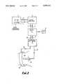
- FIG. 1shows a radio frequency generator 1 which emits radio frequency electromagnetic radiation at a frequency of 27.12 MHz.
- a frequency of 27.12 MHzis chosen as it is a standard medical frequency. However, any radio frequency in the range 500 kHz to 500 MHz could be used. Below 500 kHz the flow of electricity is not capacitative and hence the polarisation of particles does not flip between opposite directions as the current alternates and this is essential for heat production. Above 500 MHz the penetration into surrounding tissue is insufficient due to a very rapid reduction in heat production as distance increases.
- the radio frequency generator 1is connected to a linear amplifier 2 via two lines 3, 4.
- the line 3transmits the output from the radio frequency generator 1 to the linear amplifier 2 and the line 4 provides a return path from the linear amplifier 2 to the radio frequency generator 1.
- the output power of the radio frequency generator 1is approximately 70 Watts and the linear amplifier amplifies this to produce an output power on line 5 of approximately 1 kW.
- the line 5transmits the 1 kW of radio frequency at 27.12 MHz from the linear amplifier 2 to a tuning unit 6.
- the line 7provides a return path from the tuning unit 6 to the linear amplifier 2.
- the tuning unit 6is tuned to make the circuit resonate and to match the impedance of a patient 10 to the impedance of the system. This is accomplished by use of a meter 8 and when the circuit is resonating there is a zero deflection on the meter 8. The circuit is tuned using the tuning unit 6 in order to ensure that a minimum excess power remains in the circuit and that a maximum amount of power is deposited in the patient 10.
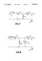
- FIGS. 7 and 8show two examples of electrical circuits suitable for use in the tuning unit 6.
- FIG. 7shows a circuit which takes the 27.12 MHz signal on the line 5 from the linear amplifier 2 and passes the signal through variable capacitors 40, 41 and outputs the 27.12 MHz signal on the line 11 to the power and SWR meter 9.
- the impedance of the inductor 42is chosen to match the impedance of the patient 10 and typically the impedance of the patient 10 is about 1000 Ohms.
- variable capacitor 40is tuned sot hat the combined impedance of the variable capacitor 40 and the inductor 42 matches the radio frequency supply load and typically this is of the order 100 Ohms.
- the other variable capacitor 41is then tuned so that the impedance of the patient 10 matches the impedance of the tuning unit 6.
- the inductor 42also compensates for the length of cable 13 connecting the system to the probe 12.
- FIG. 8shows a circuit having an inductor 45 and a variable capacitor 46 in parallel with each other and with the patient 10 and two variable capacitors 47, 48 which are in series with each other and with the patient 10.
- the inductor 45compensates for the length of the cable connecting the system to the probe 12 and the variable capacitor 47 is for tuning the impedance of the circuit shown in FIG. 8 to the load of the radio frequency generator.
- the variable capacitors 46, 48tune the impedance of the patient to the impedance of the circuit.
- the capacitors 46, 48are dual variable capacitors so that if the capacitance of the capacitor 48 is changed the capacitance of the capacitor 46 is correspondingly changed. This has the advantage over the circuit shown in FIG. 7 by giving the system a more flexible calibration range but still enabling a fixed valve inductor to be used.
- the variable capacitors 46, 48compensate for the differences in impedance between the system and the patient.
- variable capacitors 40, 41, 46, 47 and 48could be replaced by fixed capacitances, however, this would reduce the flexibility of the system.
- the output from the tuning unit 6is transmitted to a power and standing wave ratio (SWR) meter 9 by the line 11 before being supplied to the probe 12 via the line 13.
- SWRstanding wave ratio
- the probe 12emits the radio frequency electromagnetic radiation which is then detected by a return electrode in the form of a conductive belt 14 which may be a metal mesh which is insulated and completes the circuit via lines 15 and 16 and the power and SWR meter 9 to provide a return path to the radio frequency generator 1.
- the cable forming the line 15may be soldered on to the metal mesh of the belt 14 or may be crimped on to the mesh.
- the probe 12which is a conductive metal probe is inserted into the pelvic cavity.
- the apparatusis designed to destroy the endometrium in the uterus of the female patient 10.
- the probe 12is inserted into the uterus of the patient 10, as shown in FIG. 1.
- the belt 14which acts as the return electrode is placed around the patient's abdomen. The apparatus is then tuned using the tuning unit 6 and the meter 8 to the resonant series circuit formed by the probe 12 and the belt 14.
- TSEAtotal simultaneous endometrial ablation
- the magnitude of the power deposited in the patient 10is approximately 550 watts if the cable which forms the line 13 is about 4.8 m long, and this is the power absorbed by the patient 10 as heat. However, if the length of the cable is reduced to about 2.08 m the power may be reduced to about 300 W.
- the apparatuscould incorporate a variable power output so hat powers in the range 200 Watts to 1000 Watts could be absorbed. As the blood supply to the uterus is very large the blood in the uterus acts as a heat sink and so heating of the surrounding tissue is prevented.
- the probe 12has a diameter of approximately 10 mm to 12 mm.
- the uterusis not fully extended and folds and recesses remain in the wall. These folds can result in under treatment of tissue hidden by the folds.
- the diameteris less than 10 mm the surface of the probe 12 becomes much hotter and consequently provides less penetration into the surrounding tissue. A smaller probe would also mean a sharper end to the probe which would create a hot spot and this is avoided in a 10 mm diameter probe using the powers described above.
- a probe with a diameter greater than 12 mmis not practical as the cervix does not easily dilate to more than 12 mm.
- FIG. 2shows the apparatus of FIG. 1 being used to treat a patient.
- the probe 12comprises a handle 20 which is connected to a highly insulating plastic sheath 21, the line 13 is fed through the plastic sheath 21 and makes electrical contact with a metal end section 22 of the probe 12.
- the handle 20is rotatable on the plastic sheath 21 so that if the end section 22 is curved then the end section 22 maybe positioned in any orientation relative to the inside of the uterus 23.
- vaginal speculum 24which is electrically insulating and is inserted into the vagina 25 of the patient 10 prior to insertion of the probe 12 through the vagina 25 and into the uterus 23.
- the speculum 24protects the side walls 26 of the vagina 25 from accidental damage caused by localised heating by the metal end section 22 of the probe 12, which can burn a hole through the vaginal wall 26 into the other organs, such as the bladder 27 if it accidentally touches the vaginal wall 26.
- the speculum 24has a number of ribs 28 on it's outside surface 50 in order to prevent expulsion of the speculum 24 by the vagina 25.
- the speculum 24also has a lip 29 which fits into the anterior fornix 30 on the upper side of the cervix 31 so that the cervix 31 fits within the lip 29 of the speculum 24 and this helps prevent the metal end section 22 of the probe 12 contacting the vaginal wall 25.
- a guide 51is provided which may be movable on the plastic sheath 21 and/or within the speculum 24. Two examples of a guide 51 are shown in detail in FIGS. 10 and 11.
- FIG. 10shows a guide 51 of moulded plastic which has a central aperture 52 into which the plastic sheath 21 of the probe 12 is located. There are also two side apertures 53, 54, which enables an operator to view the cervix through the guide 51. An entrance 55 is also provided to enable the probe 12 to be inserted into the central aperture 52. Arcuate portion 56, 57 fit against the inside surface 58 of the speculum 24 and are resilient so that the guide 51 is retained in position in the speculum 24.
- FIG. 11shows a guide 51 which has five radially extending arm portions 59, 60, 61, 62 and 63. One end of each of the arms 59 to 63 are attached to a central section 64 which forms the central aperture 52. The other ends of the arms 59 to 63 abut against the inside surface 58 of the speculum 24 and are resilient in order to hold the guide in position within the speculum 24.
- the guide 51 in FIG. 10also has an entrance 55 through which the probe may be inserted into the central aperture 52.
- a lever 42Attached to the plastic sheath 21 is a lever 42 which enables an operator to easily rotate the orientation of the metal end section 22 relative to the handle 20.
- FIG. 3shows a first example of the metal end section 22 which is straight. Also shown is a blind bore 33 which makes electrical contact between the metal end section 22 and the conductor carrying the radio frequency signal. There is also a recess 34 into which an end 34 of the plastic sheath 21 fits.
- FIG. 4illustrates a second example of a metal end section 22 in which the metal end section 2 is curved to enable the end section 22 to more effectively contact the interior surface of the uterus.
- FIGS. 6A and 6Bshow schematically in FIGS. 6A and 6B.
- FIG. 6Ashows that with the straight end section 22 shown in FIG. 3 it is difficult for the end section 2 to effectively contact the interior surfaces of the uterus 23 without moving the probe from side to side within the uterus 23, which could cause damage to the uterus.
- FIG. 6Bthe curved end section, shown in FIG. 4, enables the end section 22 to effectively contact the interior surfaces of the uterus 23 without the probe 12 having to be moved from side to side.
- FIG. 5shows a metal end section 22 which is curved and which also has a number of apertures 35 in the external surface of the end section 22.
- This featureenables suction to be applied to the probe 12 so that air is drawn from the uterus 23 through the apertures 35 and through the probe 12 to a suitable vacuum pump attached to the probe 12.
- the suction applied to the uterus 23 through the probe 12enables the walls of the uterus to be drawn onto the end section 22 of the probe 12 and this also improves the contact between the walls of the uterus 23 and the surface of the end section 22.
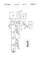
- a thermistor 36is mounted in the tip of the end section 22 and is connected to an external monitoring circuit 90 as shown in FIG. 13.
- the thermistor 36is connected to the monitor 90 via two lines 91, 92.
- Each line 91, 92has three reed relay switches 93, 94, 104, and the switches 93, 94, 104 are high voltage isolation reed switches which have a blocking isolation of about 3 kV.
- the switches 93, 94are operated by movable magnets 95 which are moved by diaphragm air operated switches 96 and the air switches 96 are connected via air lines 97 and a valve 98 to a compressor 99.
- a DC power supply 100is connected to a switch 101 and two coils 102, 103.
- the coil 102is adjacent to the valve 98 and the coil 103 is adjacent to the pair of reed switches 104 in the lines 91, 92.
- the switch 101When the switch 101 is open no current from the supply 100 flows through the coils 102, 103 and so the valve 98 is open to the atmosphere and the switches 104 connect the temperature monitor 90 to an earth potential 105.
- the switch 101is closed current from the DC supply 100 flows through the coils 102, 103 and the current flowing through the coils 102, 103 generates a magnetic field in the vicinity of the coils 102, 103. This magnetic field actuates the valve 98 causing the valve 98 to close.
- the radio frequency generator 1is switched off by a switch (not shown). This prevents the radio frequency generated by the generator 1 from interfering with the monitoring of the temperature of the thermistor 36 by the monitor 90 and also prevents the power from the radio frequency becoming dissipated into the temperature monitoring circuit and burning out the thermistor 36 and/or the monitor 90.
- the air lines 97 and the switches 96are all manufactured from non-metallic components to prevent radio frequency oscillation being generated in their components.
- the switch 101is opened which causes the switches 104 to re-connect the circuit 20 to the earth potential 105 and the value 98 to open. This allows the air pressure in the air switches 96 and the lines 97 to drop and so the switches 96 are de-activated and the magnets 95 are returned to their original position by the biasing action of the springs 106 which causes the reed switches 93, 94 to open.
- the radio frequency generator 1is switched on again and the ablation of the endometrium continues.
- the temperature sampling procedures as described aboveoccurs at pre-determined intervals so that the temperature at the probe end is regularly monitored and displayed on a display (not shown) which is visible to an operator.
- FIG. 12shows a second example of apparatus for achieving TSEA.
- the apparatusis the same as the apparatus shown in FIG. 1, except that the power and SWA meter 9 is not used and the tuning unit 6 is connected directly to the lines 13, 15. Instead of the power and SWR meter 9, a forward power measurement and normalised reflected power indication unit 80 is located between the linear amplifier 2 and the tuning unit 6. There is also a fault interlock line 81 which connects the indication unit 80 directly to the radio frequency generator 1.
- the indication unit 80monitors the tuning unit 6 and the status of the tuning unit 6 is related to the power being dissipated in the patient 10. Hence, the indicator 80 indirectly monitors the patient 10. If the indicator 80 detects that the reflected power rises above a pre-determined level then this indicates that there is a fault in the apparatus and the indicator 80 sends a signal on the line 81 to cut off the radio frequency generator 1.
- Treatment of menorrhagia using the apparatus described above and shown in FIG. 1 to achieve TSEAis radically different from the laser and diathermy loop methods. In these methods only small areas of the endometrium can be treated at one time and hence the radio frequency treatment described above is a much faster method of treatment. Therefore this treatment is in the long term significantly cheaper than other known methods of treatment such as using lasers or a diathermy loop or by performing a hysterectomy operation. Modifications and improvements may be incorporated without departing from the scope of the invention.
Landscapes
- Health & Medical Sciences (AREA)
- Engineering & Computer Science (AREA)
- Life Sciences & Earth Sciences (AREA)
- Animal Behavior & Ethology (AREA)
- Veterinary Medicine (AREA)
- Nuclear Medicine, Radiotherapy & Molecular Imaging (AREA)
- Public Health (AREA)
- Surgery (AREA)
- Biomedical Technology (AREA)
- General Health & Medical Sciences (AREA)
- Otolaryngology (AREA)
- Molecular Biology (AREA)
- Medical Informatics (AREA)
- Heart & Thoracic Surgery (AREA)
- Physics & Mathematics (AREA)
- Plasma & Fusion (AREA)
- Radiology & Medical Imaging (AREA)
- Surgical Instruments (AREA)
- Electrotherapy Devices (AREA)
- Magnetic Treatment Devices (AREA)
Abstract
Description
Claims (5)
Applications Claiming Priority (6)
| Application Number | Priority Date | Filing Date | Title |
|---|---|---|---|
| GB8914118.8 | 1989-06-20 | ||
| GB898914118AGB8914118D0 (en) | 1989-06-20 | 1989-06-20 | Radio frequency apparatus |
| GB8914933.0 | 1989-06-29 | ||
| GB898914933AGB8914933D0 (en) | 1989-06-29 | 1989-06-29 | Radio frequency apparatus |
| GB8928347.7 | 1989-12-15 | ||
| GB898928347AGB8928347D0 (en) | 1989-12-15 | 1989-12-15 | Radiation generation apparatus |
Publications (1)
| Publication Number | Publication Date |
|---|---|
| US5188122Atrue US5188122A (en) | 1993-02-23 |
Family
ID=27264531
Family Applications (1)
| Application Number | Title | Priority Date | Filing Date |
|---|---|---|---|
| US07/540,614Expired - Fee RelatedUS5188122A (en) | 1989-06-20 | 1990-06-20 | Electromagnetic energy generation method |
Country Status (4)
| Country | Link |
|---|---|
| US (1) | US5188122A (en) |
| EP (1) | EP0407057B1 (en) |
| AT (1) | ATE126714T1 (en) |
| DE (1) | DE69021798D1 (en) |
Cited By (52)
| Publication number | Priority date | Publication date | Assignee | Title |
|---|---|---|---|---|
| WO1993021846A1 (en)* | 1992-05-01 | 1993-11-11 | Vesta Medical, Inc. | Endometrial ablation apparatus and method |
| WO1994023794A1 (en)* | 1993-04-14 | 1994-10-27 | Vesta Medical, Inc. | Method and apparatus for endometrial ablation |
| US5364392A (en)* | 1993-05-14 | 1994-11-15 | Fidus Medical Technology Corporation | Microwave ablation catheter system with impedance matching tuner and method |
| WO1994026188A1 (en)* | 1993-05-14 | 1994-11-24 | Fidus Medical Technology Corporation | Tunable microwave ablation catheter system and method |
| US5445168A (en)* | 1993-01-25 | 1995-08-29 | Krebs; Helmut | Method for treating interuterine walls using a resectoscope |
| US5447526A (en)* | 1992-12-24 | 1995-09-05 | Karsdon; Jeffrey | Transcutaneous electric muscle/nerve controller/feedback unit |
| FR2720948A1 (en)* | 1994-06-10 | 1995-12-15 | Sadis Bruker Spectrospin | Apparatus for in situ treatment by hyperthermia or thermotherapy. |
| US5505730A (en)* | 1994-06-24 | 1996-04-09 | Stuart D. Edwards | Thin layer ablation apparatus |
| US5562720A (en)* | 1992-05-01 | 1996-10-08 | Vesta Medical, Inc. | Bipolar/monopolar endometrial ablation device and method |
| US5575788A (en)* | 1994-06-24 | 1996-11-19 | Stuart D. Edwards | Thin layer ablation apparatus |
| US5681308A (en)* | 1994-06-24 | 1997-10-28 | Stuart D. Edwards | Ablation apparatus for cardiac chambers |
| US5693082A (en)* | 1993-05-14 | 1997-12-02 | Fidus Medical Technology Corporation | Tunable microwave ablation catheter system and method |
| US5741249A (en)* | 1996-10-16 | 1998-04-21 | Fidus Medical Technology Corporation | Anchoring tip assembly for microwave ablation catheter |
| US5769880A (en)* | 1996-04-12 | 1998-06-23 | Novacept | Moisture transport system for contact electrocoagulation |
| US5800493A (en)* | 1995-04-26 | 1998-09-01 | Gynecare, Inc. | Intrauterine ablation system |
| US5810803A (en)* | 1996-10-16 | 1998-09-22 | Fidus Medical Technology Corporation | Conformal positioning assembly for microwave ablation catheter |
| US5816248A (en)* | 1996-03-29 | 1998-10-06 | Iotek, Inc. | Channeled vaginal insert and method for treating urogenital disorders |
| US5988169A (en)* | 1996-03-29 | 1999-11-23 | Iotek, Inc. | Vaginal insert and method for treating urogenital disorders |
| US6019757A (en)* | 1995-07-07 | 2000-02-01 | Target Therapeutics, Inc. | Endoluminal electro-occlusion detection apparatus and method |
| US6030375A (en)* | 1996-03-29 | 2000-02-29 | Iotek, Inc. | Compressible vaginal insert and method for treating urogenital disorders |
| US6086581A (en)* | 1992-09-29 | 2000-07-11 | Ep Technologies, Inc. | Large surface cardiac ablation catheter that assumes a low profile during introduction into the heart |
| US20020087151A1 (en)* | 2000-12-29 | 2002-07-04 | Afx, Inc. | Tissue ablation apparatus with a sliding ablation instrument and method |
| US20020128642A1 (en)* | 1998-10-23 | 2002-09-12 | Afx, Inc. | Directional microwave ablation instrument with marking device |
| US20020193783A1 (en)* | 2000-01-18 | 2002-12-19 | Afx, Inc. | Microwave ablation instrument with flexible antenna assembly and method |
| US20030163128A1 (en)* | 2000-12-29 | 2003-08-28 | Afx, Inc. | Tissue ablation system with a sliding ablating device and method |
| US20040106937A1 (en)* | 2002-06-21 | 2004-06-03 | Afx, Inc. | Clamp accessory and method for an ablation instrument |
| US20040138652A1 (en)* | 2000-04-12 | 2004-07-15 | Afx, Inc. | Electrode arrangement for use in a medical instrument |
| US6813520B2 (en) | 1996-04-12 | 2004-11-02 | Novacept | Method for ablating and/or coagulating tissue using moisture transport |
| US20050075629A1 (en)* | 2002-02-19 | 2005-04-07 | Afx, Inc. | Apparatus and method for assessing tissue ablation transmurality |
| US20050085880A1 (en)* | 1996-04-12 | 2005-04-21 | Csaba Truckai | Moisture transport system for contact electrocoagulation |
| US6890331B2 (en) | 2000-09-28 | 2005-05-10 | Xo Care A/S | Electrosurgical apparatus |
| US7079882B1 (en) | 2000-01-22 | 2006-07-18 | Richard Schmidt | Method and apparatus for quantifying nerve and neural-muscular integrity related to pelvic organs or pelvic floor functions |
| US7099717B2 (en) | 2002-01-03 | 2006-08-29 | Afx Inc. | Catheter having improved steering |
| US20060206107A1 (en)* | 1999-05-28 | 2006-09-14 | Afx, Inc. | Monopole tip for ablation catheter and methods for using same |
| US20070055225A1 (en)* | 2005-09-07 | 2007-03-08 | Dodd Gerald D Iii | Method and apparatus for electromagnetic ablation of biological tissue |
| US7192427B2 (en) | 2002-02-19 | 2007-03-20 | Afx, Inc. | Apparatus and method for assessing transmurality of a tissue ablation |
| US20070118102A1 (en)* | 2005-11-18 | 2007-05-24 | Olympus Medical Systems Corp. | Electrosurgical device |
| US7226446B1 (en) | 1999-05-04 | 2007-06-05 | Dinesh Mody | Surgical microwave ablation assembly |
| US20080071269A1 (en)* | 2006-09-18 | 2008-03-20 | Cytyc Corporation | Curved Endoscopic Medical Device |
| US20080071257A1 (en)* | 2006-09-18 | 2008-03-20 | Cytyc Corporation | Power Ramping During RF Ablation |
| US20090131926A1 (en)* | 2007-11-16 | 2009-05-21 | Tyco Healthcare Group Lp | Dynamically Matched Microwave Antenna for Tissue Ablation |
| US20090228002A1 (en)* | 2008-03-04 | 2009-09-10 | Rioux Robert F | Electromagnetic energy assisted tissue penetration device and method |
| US7674260B2 (en) | 2005-04-28 | 2010-03-09 | Cytyc Corporation | Emergency hemostasis device utilizing energy |
| US7731712B2 (en) | 2004-12-20 | 2010-06-08 | Cytyc Corporation | Method and system for transcervical tubal occlusion |
| US7846160B2 (en) | 2006-12-21 | 2010-12-07 | Cytyc Corporation | Method and apparatus for sterilization |
| US20110202108A1 (en)* | 2010-02-18 | 2011-08-18 | Rainbow Medical Ltd. | Electrical menorrhagia treatment |
| US20130006334A1 (en)* | 2010-02-04 | 2013-01-03 | Mauro Galli | Device for the treatment of the vaginal canal and relevant equipment |
| US8551082B2 (en) | 1998-05-08 | 2013-10-08 | Cytyc Surgical Products | Radio-frequency generator for powering an ablation device |
| WO2014037591A1 (en)* | 2012-09-06 | 2014-03-13 | Sanchez Jaime Maria Del Pilar | Intracavitary element |
| US8747398B2 (en) | 2007-09-13 | 2014-06-10 | Covidien Lp | Frequency tuning in a microwave electrosurgical system |
| US9486243B2 (en) | 2011-11-08 | 2016-11-08 | Covidien Lp | Systems and methods for treatment of premenstrual dysphoric disorders |
| EP3632506A4 (en)* | 2017-05-29 | 2020-12-09 | Sanchez Jaime, Maria del Pilar | Active intracavitary accessory |
Families Citing this family (23)
| Publication number | Priority date | Publication date | Assignee | Title |
|---|---|---|---|---|
| DE4122091A1 (en)* | 1991-07-01 | 1993-01-14 | Funkwerk Koepenick Gmbh I A | H.F. generator circuit for medical short wave therapy appts. - has quartz oscillator, level regulator and two power amplifiers for level control via OR gate |
| CH684824A5 (en)* | 1991-10-24 | 1995-01-13 | Erik Larsen | Apparatus for effecting the transport of protons from intracorporeal electrolyte liquids. |
| DE4242126C1 (en)* | 1992-12-14 | 1994-07-07 | Rainer Dr Deckardt | Surgical instrument for endometrium destruction |
| CA2167690C (en)* | 1993-10-22 | 1999-07-06 | Anthony John Mccartney | Transvaginal tube as an aid to laparoscopic surgery |
| US6572631B1 (en) | 1993-10-22 | 2003-06-03 | Gynetech Pty Ltd. | Transvaginal tube as an aid to laparoscopic surgery |
| CA2197767C (en)* | 1994-08-17 | 2001-01-02 | Arthur A. Pilla | Electrotherapeutic system |
| DE4442690A1 (en)* | 1994-11-30 | 1996-06-05 | Delma Elektro Med App | Interstitial thermotherapy facility for tumors with high-frequency currents |
| US6293942B1 (en) | 1995-06-23 | 2001-09-25 | Gyrus Medical Limited | Electrosurgical generator method |
| KR19990028365A (en) | 1995-06-23 | 1999-04-15 | 니겔 마크 고블 | Electrosurgical surgical instruments |
| US6780180B1 (en) | 1995-06-23 | 2004-08-24 | Gyrus Medical Limited | Electrosurgical instrument |
| US6015406A (en) | 1996-01-09 | 2000-01-18 | Gyrus Medical Limited | Electrosurgical instrument |
| EP1025807B1 (en) | 1995-06-23 | 2004-12-08 | Gyrus Medical Limited | An electrosurgical instrument |
| US5743905A (en)* | 1995-07-07 | 1998-04-28 | Target Therapeutics, Inc. | Partially insulated occlusion device |
| US6013076A (en) | 1996-01-09 | 2000-01-11 | Gyrus Medical Limited | Electrosurgical instrument |
| US6090106A (en) | 1996-01-09 | 2000-07-18 | Gyrus Medical Limited | Electrosurgical instrument |
| US6565561B1 (en) | 1996-06-20 | 2003-05-20 | Cyrus Medical Limited | Electrosurgical instrument |
| GB9612993D0 (en) | 1996-06-20 | 1996-08-21 | Gyrus Medical Ltd | Electrosurgical instrument |
| GB2314274A (en) | 1996-06-20 | 1997-12-24 | Gyrus Medical Ltd | Electrode construction for an electrosurgical instrument |
| SE509241C2 (en)* | 1996-07-18 | 1998-12-21 | Radinvent Ab | Devices for electrodynamic radiation therapy of tumor diseases |
| US6126682A (en) | 1996-08-13 | 2000-10-03 | Oratec Interventions, Inc. | Method for treating annular fissures in intervertebral discs |
| GB9626512D0 (en) | 1996-12-20 | 1997-02-05 | Gyrus Medical Ltd | An improved electrosurgical generator and system |
| GB9807303D0 (en) | 1998-04-03 | 1998-06-03 | Gyrus Medical Ltd | An electrode assembly for an electrosurgical instrument |
| US7744596B2 (en)* | 2005-10-13 | 2010-06-29 | Boston Scientific Scimed, Inc. | Magnetically augmented radio frequency ablation |
Citations (16)
| Publication number | Priority date | Publication date | Assignee | Title |
|---|---|---|---|---|
| SU219094A1 (en)* | В. Ю. Скульский | VAGINAL ELECTRODE FOR UHF-THERAPY | ||
| US1620929A (en)* | 1925-02-05 | 1927-03-15 | George W Wallerich | Heat-therapy method and means |
| US1827306A (en)* | 1925-09-14 | 1931-10-13 | Fischer & Co H G | Electrode |
| FR57824E (en)* | 1947-11-20 | 1953-09-17 | Improvements to electrodes used in electrotherapy for high frequency applications | |
| US3645265A (en)* | 1969-06-25 | 1972-02-29 | Gregory Majzlin | Intrauterine cauterizing device |
| US3840016A (en)* | 1972-03-10 | 1974-10-08 | H Lindemann | Electrocoagulation-bougie for the intrauterine tube sterilization |
| US4057063A (en)* | 1975-04-11 | 1977-11-08 | U.S. Philips Corporation | Device for sterilization by transuterine tube coagulation |
| EP0115420A2 (en)* | 1983-01-24 | 1984-08-08 | Kureha Kagaku Kogyo Kabushiki Kaisha | A device for hyperthermia |
| WO1987001276A1 (en)* | 1985-08-28 | 1987-03-12 | Sonomed Technology, Inc. | Endoscopic ultrasonic aspirator with modified working tip |
| DE8527331U1 (en)* | 1985-09-25 | 1987-12-10 | Celltek GmbH & Co KG, 3000 Hannover | Sphincter trainer |
| US4865047A (en)* | 1988-06-30 | 1989-09-12 | City Of Hope | Hyperthermia applicator |
| US4949718A (en)* | 1988-09-09 | 1990-08-21 | Gynelab Products | Intrauterine cauterizing apparatus |
| US4960133A (en)* | 1988-11-21 | 1990-10-02 | Brunswick Manufacturing Co., Inc. | Esophageal electrode |
| US4961435A (en)* | 1987-10-28 | 1990-10-09 | Kureha Kagaku Kogyo Kabushiki Kaishi | High-frequency capacitive heating electrode device |
| US4979948A (en)* | 1989-04-13 | 1990-12-25 | Purdue Research Foundation | Method and apparatus for thermally destroying a layer of an organ |
| US5084044A (en)* | 1989-07-14 | 1992-01-28 | Ciron Corporation | Apparatus for endometrial ablation and method of using same |
- 1990
- 1990-06-20ATAT90306702Tpatent/ATE126714T1/ennot_activeIP Right Cessation
- 1990-06-20USUS07/540,614patent/US5188122A/ennot_activeExpired - Fee Related
- 1990-06-20DEDE69021798Tpatent/DE69021798D1/ennot_activeExpired - Lifetime
- 1990-06-20EPEP90306702Apatent/EP0407057B1/ennot_activeExpired - Lifetime
Patent Citations (18)
| Publication number | Priority date | Publication date | Assignee | Title |
|---|---|---|---|---|
| SU219094A1 (en)* | В. Ю. Скульский | VAGINAL ELECTRODE FOR UHF-THERAPY | ||
| US1620929A (en)* | 1925-02-05 | 1927-03-15 | George W Wallerich | Heat-therapy method and means |
| US1827306A (en)* | 1925-09-14 | 1931-10-13 | Fischer & Co H G | Electrode |
| FR57824E (en)* | 1947-11-20 | 1953-09-17 | Improvements to electrodes used in electrotherapy for high frequency applications | |
| US3645265A (en)* | 1969-06-25 | 1972-02-29 | Gregory Majzlin | Intrauterine cauterizing device |
| US3840016A (en)* | 1972-03-10 | 1974-10-08 | H Lindemann | Electrocoagulation-bougie for the intrauterine tube sterilization |
| US4057063A (en)* | 1975-04-11 | 1977-11-08 | U.S. Philips Corporation | Device for sterilization by transuterine tube coagulation |
| US4676258A (en)* | 1983-01-24 | 1987-06-30 | Kureha Kagaku Kogyo Kabushiki Kaisha | Device for hyperthermia |
| EP0115420A2 (en)* | 1983-01-24 | 1984-08-08 | Kureha Kagaku Kogyo Kabushiki Kaisha | A device for hyperthermia |
| WO1987001276A1 (en)* | 1985-08-28 | 1987-03-12 | Sonomed Technology, Inc. | Endoscopic ultrasonic aspirator with modified working tip |
| DE8527331U1 (en)* | 1985-09-25 | 1987-12-10 | Celltek GmbH & Co KG, 3000 Hannover | Sphincter trainer |
| US4961435A (en)* | 1987-10-28 | 1990-10-09 | Kureha Kagaku Kogyo Kabushiki Kaishi | High-frequency capacitive heating electrode device |
| US4865047A (en)* | 1988-06-30 | 1989-09-12 | City Of Hope | Hyperthermia applicator |
| US4949718A (en)* | 1988-09-09 | 1990-08-21 | Gynelab Products | Intrauterine cauterizing apparatus |
| US4949718B1 (en)* | 1988-09-09 | 1998-11-10 | Gynelab Products | Intrauterine cauterizing apparatus |
| US4960133A (en)* | 1988-11-21 | 1990-10-02 | Brunswick Manufacturing Co., Inc. | Esophageal electrode |
| US4979948A (en)* | 1989-04-13 | 1990-12-25 | Purdue Research Foundation | Method and apparatus for thermally destroying a layer of an organ |
| US5084044A (en)* | 1989-07-14 | 1992-01-28 | Ciron Corporation | Apparatus for endometrial ablation and method of using same |
Cited By (97)
| Publication number | Priority date | Publication date | Assignee | Title |
|---|---|---|---|---|
| WO1993021846A1 (en)* | 1992-05-01 | 1993-11-11 | Vesta Medical, Inc. | Endometrial ablation apparatus and method |
| US5562720A (en)* | 1992-05-01 | 1996-10-08 | Vesta Medical, Inc. | Bipolar/monopolar endometrial ablation device and method |
| US6041260A (en)* | 1992-05-01 | 2000-03-21 | Vesta Medical, Inc. | Method and apparatus for endometrial ablation |
| US5713942A (en)* | 1992-05-01 | 1998-02-03 | Vesta Medical, Inc. | Body cavity ablation apparatus and model |
| US5277201A (en)* | 1992-05-01 | 1994-01-11 | Vesta Medical, Inc. | Endometrial ablation apparatus and method |
| US5443470A (en)* | 1992-05-01 | 1995-08-22 | Vesta Medical, Inc. | Method and apparatus for endometrial ablation |
| AU668943B2 (en)* | 1992-05-01 | 1996-05-23 | Covidien Ag | Endometrial ablation apparatus and method |
| US6086581A (en)* | 1992-09-29 | 2000-07-11 | Ep Technologies, Inc. | Large surface cardiac ablation catheter that assumes a low profile during introduction into the heart |
| US5447526A (en)* | 1992-12-24 | 1995-09-05 | Karsdon; Jeffrey | Transcutaneous electric muscle/nerve controller/feedback unit |
| US5713940A (en)* | 1992-12-24 | 1998-02-03 | Jeffrey Karsdon | Transcutaneous electric muscle/nerve controller/feedback unit |
| US5445168A (en)* | 1993-01-25 | 1995-08-29 | Krebs; Helmut | Method for treating interuterine walls using a resectoscope |
| WO1994023794A1 (en)* | 1993-04-14 | 1994-10-27 | Vesta Medical, Inc. | Method and apparatus for endometrial ablation |
| WO1994026188A1 (en)* | 1993-05-14 | 1994-11-24 | Fidus Medical Technology Corporation | Tunable microwave ablation catheter system and method |
| US5405346A (en)* | 1993-05-14 | 1995-04-11 | Fidus Medical Technology Corporation | Tunable microwave ablation catheter |
| US5957969A (en)* | 1993-05-14 | 1999-09-28 | Fidus Medical Technology Corporation | Tunable microwave ablation catheter system and method |
| US5693082A (en)* | 1993-05-14 | 1997-12-02 | Fidus Medical Technology Corporation | Tunable microwave ablation catheter system and method |
| US5364392A (en)* | 1993-05-14 | 1994-11-15 | Fidus Medical Technology Corporation | Microwave ablation catheter system with impedance matching tuner and method |
| FR2720948A1 (en)* | 1994-06-10 | 1995-12-15 | Sadis Bruker Spectrospin | Apparatus for in situ treatment by hyperthermia or thermotherapy. |
| WO1995034345A1 (en)* | 1994-06-10 | 1995-12-21 | Sadis Bruker Spectrospin Societe Anonyme De Diffusion De L'instrumentation Scientifique Bruker Spectrospin (Societe Anonyme A Directoire) | Apparatus for in situ treatment by hyperthermia or thermotherapy |
| US5681308A (en)* | 1994-06-24 | 1997-10-28 | Stuart D. Edwards | Ablation apparatus for cardiac chambers |
| US5505730A (en)* | 1994-06-24 | 1996-04-09 | Stuart D. Edwards | Thin layer ablation apparatus |
| US5569241A (en)* | 1994-06-24 | 1996-10-29 | Vidacare, Inc. | Thin layer ablation apparatus |
| US5769846A (en)* | 1994-06-24 | 1998-06-23 | Stuart D. Edwards | Ablation apparatus for cardiac chambers |
| US5558672A (en)* | 1994-06-24 | 1996-09-24 | Vidacare, Inc. | Thin layer ablation apparatus |
| US5827273A (en)* | 1994-06-24 | 1998-10-27 | Stuart D. Edwards | Thin layer ablation apparatus |
| US5575788A (en)* | 1994-06-24 | 1996-11-19 | Stuart D. Edwards | Thin layer ablation apparatus |
| US5800493A (en)* | 1995-04-26 | 1998-09-01 | Gynecare, Inc. | Intrauterine ablation system |
| US6019757A (en)* | 1995-07-07 | 2000-02-01 | Target Therapeutics, Inc. | Endoluminal electro-occlusion detection apparatus and method |
| US6030375A (en)* | 1996-03-29 | 2000-02-29 | Iotek, Inc. | Compressible vaginal insert and method for treating urogenital disorders |
| US5816248A (en)* | 1996-03-29 | 1998-10-06 | Iotek, Inc. | Channeled vaginal insert and method for treating urogenital disorders |
| US5988169A (en)* | 1996-03-29 | 1999-11-23 | Iotek, Inc. | Vaginal insert and method for treating urogenital disorders |
| US20100036372A1 (en)* | 1996-04-12 | 2010-02-11 | Csaba Truckai | Moisture transport system for contact electrocoagulation |
| US6813520B2 (en) | 1996-04-12 | 2004-11-02 | Novacept | Method for ablating and/or coagulating tissue using moisture transport |
| US5769880A (en)* | 1996-04-12 | 1998-06-23 | Novacept | Moisture transport system for contact electrocoagulation |
| US7512445B2 (en)* | 1996-04-12 | 2009-03-31 | Cytyc Corporation | Moisture transport system for contact electrocoagulation |
| US7604633B2 (en)* | 1996-04-12 | 2009-10-20 | Cytyc Corporation | Moisture transport system for contact electrocoagulation |
| US20050267468A1 (en)* | 1996-04-12 | 2005-12-01 | Csaba Truckai | Moisture transport system for contact electrocoagulation |
| US20050085880A1 (en)* | 1996-04-12 | 2005-04-21 | Csaba Truckai | Moisture transport system for contact electrocoagulation |
| US9247989B2 (en) | 1996-04-12 | 2016-02-02 | Cytyc Surgical Products | Moisture transport system for contact electrocoagulation |
| US9095348B2 (en) | 1996-04-12 | 2015-08-04 | Cytyc Surgical Products | Moisture transport system for contact electrocoagulation |
| US8998898B2 (en)* | 1996-04-12 | 2015-04-07 | Cytyc Surgical Products | Moisture transport system for contact electrocoagulation |
| US20140249527A1 (en)* | 1996-04-12 | 2014-09-04 | Cytyc Surgical Products | Moisture Transport System for Contact Electrocoagulation |
| US8506563B2 (en)* | 1996-04-12 | 2013-08-13 | Cytyc Surgical Products | Moisture transport system for contact electrocoagulation |
| US5741249A (en)* | 1996-10-16 | 1998-04-21 | Fidus Medical Technology Corporation | Anchoring tip assembly for microwave ablation catheter |
| US5810803A (en)* | 1996-10-16 | 1998-09-22 | Fidus Medical Technology Corporation | Conformal positioning assembly for microwave ablation catheter |
| US8551082B2 (en) | 1998-05-08 | 2013-10-08 | Cytyc Surgical Products | Radio-frequency generator for powering an ablation device |
| US9554853B2 (en) | 1998-05-08 | 2017-01-31 | Hologic, Inc. | Radio-frequency generator for powering an ablation device |
| US7115126B2 (en) | 1998-10-23 | 2006-10-03 | Afx Inc. | Directional microwave ablation instrument with off-set energy delivery portion |
| US7387627B2 (en) | 1998-10-23 | 2008-06-17 | Maquet Cardiovascular Llc | Vacuum-assisted securing apparatus for a microwave ablation instrument |
| US20020128642A1 (en)* | 1998-10-23 | 2002-09-12 | Afx, Inc. | Directional microwave ablation instrument with marking device |
| US20020193786A1 (en)* | 1998-10-23 | 2002-12-19 | Dany Berube | Directional microwave ablation instrument with off-set energy delivery portion |
| US7052491B2 (en) | 1998-10-23 | 2006-05-30 | Afx, Inc. | Vacuum-assisted securing apparatus for a microwave ablation instrument |
| US7226446B1 (en) | 1999-05-04 | 2007-06-05 | Dinesh Mody | Surgical microwave ablation assembly |
| US20070203480A1 (en)* | 1999-05-04 | 2007-08-30 | Dinesh Mody | Surgical microwave ablation assembly |
| US20060206107A1 (en)* | 1999-05-28 | 2006-09-14 | Afx, Inc. | Monopole tip for ablation catheter and methods for using same |
| US7346399B2 (en) | 1999-05-28 | 2008-03-18 | Afx, Inc. | Monopole tip for ablation catheter |
| US20060116673A1 (en)* | 2000-01-18 | 2006-06-01 | Jules Gauthier | Ablation instrument and method |
| US20020193783A1 (en)* | 2000-01-18 | 2002-12-19 | Afx, Inc. | Microwave ablation instrument with flexible antenna assembly and method |
| US7033352B1 (en) | 2000-01-18 | 2006-04-25 | Afx, Inc. | Flexible ablation instrument |
| US7301131B2 (en) | 2000-01-18 | 2007-11-27 | Afx, Inc. | Microwave ablation instrument with flexible antenna assembly and method |
| US7079882B1 (en) | 2000-01-22 | 2006-07-18 | Richard Schmidt | Method and apparatus for quantifying nerve and neural-muscular integrity related to pelvic organs or pelvic floor functions |
| US20050251129A1 (en)* | 2000-04-12 | 2005-11-10 | Dany Berube | Electrode arrangement for use in a medical instrument |
| US7156841B2 (en) | 2000-04-12 | 2007-01-02 | Afx, Inc. | Electrode arrangement for use in a medical instrument |
| US20040138652A1 (en)* | 2000-04-12 | 2004-07-15 | Afx, Inc. | Electrode arrangement for use in a medical instrument |
| US6976986B2 (en) | 2000-04-12 | 2005-12-20 | Afx, Inc. | Electrode arrangement for use in a medical instrument |
| US6890331B2 (en) | 2000-09-28 | 2005-05-10 | Xo Care A/S | Electrosurgical apparatus |
| US20030109868A1 (en)* | 2000-12-29 | 2003-06-12 | Afx, Inc. | Medical instrument positioning tool and method |
| US20030050631A1 (en)* | 2000-12-29 | 2003-03-13 | Afx, Inc. | Tissue ablation apparatus with a sliding ablation instrument and method |
| US20030163128A1 (en)* | 2000-12-29 | 2003-08-28 | Afx, Inc. | Tissue ablation system with a sliding ablating device and method |
| US7303560B2 (en) | 2000-12-29 | 2007-12-04 | Afx, Inc. | Method of positioning a medical instrument |
| US20020087151A1 (en)* | 2000-12-29 | 2002-07-04 | Afx, Inc. | Tissue ablation apparatus with a sliding ablation instrument and method |
| US7099717B2 (en) | 2002-01-03 | 2006-08-29 | Afx Inc. | Catheter having improved steering |
| US7192427B2 (en) | 2002-02-19 | 2007-03-20 | Afx, Inc. | Apparatus and method for assessing transmurality of a tissue ablation |
| US20050075629A1 (en)* | 2002-02-19 | 2005-04-07 | Afx, Inc. | Apparatus and method for assessing tissue ablation transmurality |
| US20040106937A1 (en)* | 2002-06-21 | 2004-06-03 | Afx, Inc. | Clamp accessory and method for an ablation instrument |
| US7731712B2 (en) | 2004-12-20 | 2010-06-08 | Cytyc Corporation | Method and system for transcervical tubal occlusion |
| US7674260B2 (en) | 2005-04-28 | 2010-03-09 | Cytyc Corporation | Emergency hemostasis device utilizing energy |
| US20070055225A1 (en)* | 2005-09-07 | 2007-03-08 | Dodd Gerald D Iii | Method and apparatus for electromagnetic ablation of biological tissue |
| US7722602B2 (en)* | 2005-11-18 | 2010-05-25 | Olympus Medical Systems Corp. | Electrosurgical device |
| US20070118102A1 (en)* | 2005-11-18 | 2007-05-24 | Olympus Medical Systems Corp. | Electrosurgical device |
| US20080071257A1 (en)* | 2006-09-18 | 2008-03-20 | Cytyc Corporation | Power Ramping During RF Ablation |
| US20080071269A1 (en)* | 2006-09-18 | 2008-03-20 | Cytyc Corporation | Curved Endoscopic Medical Device |
| US8486060B2 (en) | 2006-09-18 | 2013-07-16 | Cytyc Corporation | Power ramping during RF ablation |
| US7846160B2 (en) | 2006-12-21 | 2010-12-07 | Cytyc Corporation | Method and apparatus for sterilization |
| US8747398B2 (en) | 2007-09-13 | 2014-06-10 | Covidien Lp | Frequency tuning in a microwave electrosurgical system |
| US9498285B2 (en) | 2007-09-13 | 2016-11-22 | Covidien Lp | Impedance matching in a microwave electrosurgical system |
| US20090131926A1 (en)* | 2007-11-16 | 2009-05-21 | Tyco Healthcare Group Lp | Dynamically Matched Microwave Antenna for Tissue Ablation |
| US8968291B2 (en) | 2007-11-16 | 2015-03-03 | Covidien Lp | Dynamically matched microwave antenna for tissue ablation |
| US8280525B2 (en) | 2007-11-16 | 2012-10-02 | Vivant Medical, Inc. | Dynamically matched microwave antenna for tissue ablation |
| US9579151B2 (en) | 2007-11-16 | 2017-02-28 | Covidien Lp | Dynamically matched microwave antenna for tissue ablation |
| US20090228002A1 (en)* | 2008-03-04 | 2009-09-10 | Rioux Robert F | Electromagnetic energy assisted tissue penetration device and method |
| US20130006334A1 (en)* | 2010-02-04 | 2013-01-03 | Mauro Galli | Device for the treatment of the vaginal canal and relevant equipment |
| US20110202108A1 (en)* | 2010-02-18 | 2011-08-18 | Rainbow Medical Ltd. | Electrical menorrhagia treatment |
| US9486243B2 (en) | 2011-11-08 | 2016-11-08 | Covidien Lp | Systems and methods for treatment of premenstrual dysphoric disorders |
| ES2453445A1 (en)* | 2012-09-06 | 2014-04-07 | María Del Pilar SÁNCHEZ JAIME | intracavitary element |
| WO2014037591A1 (en)* | 2012-09-06 | 2014-03-13 | Sanchez Jaime Maria Del Pilar | Intracavitary element |
| EP3632506A4 (en)* | 2017-05-29 | 2020-12-09 | Sanchez Jaime, Maria del Pilar | Active intracavitary accessory |
Also Published As
| Publication number | Publication date |
|---|---|
| EP0407057B1 (en) | 1995-08-23 |
| ATE126714T1 (en) | 1995-09-15 |
| EP0407057A1 (en) | 1991-01-09 |
| DE69021798D1 (en) | 1995-09-28 |
Similar Documents
| Publication | Publication Date | Title |
|---|---|---|
| US5188122A (en) | Electromagnetic energy generation method | |
| US6485486B1 (en) | System and methods for fallopian tube occlusion | |
| JP6605673B2 (en) | Dual-function plasma and non-ionizing microwave coagulation electrosurgical instrument and electrosurgical device incorporating the same | |
| KR102323636B1 (en) | Surgical snare with ability to deliver electromagnetic energy and/or thermal plasma into biological tissue | |
| JP7402525B2 (en) | electrosurgical generator | |
| ES2688300T3 (en) | Applicator for plasma sterilization by microwave | |
| EP2789305B1 (en) | Multi-mode electrosurgical apparatus | |
| EP1076522B1 (en) | Microwave applicator | |
| CN107550560B (en) | Isolation circuit for electrosurgical device for cutting biological tissue | |
| US20250090228A1 (en) | Medical treatment tool | |
| WO1995005869A1 (en) | A probe for a microwave apparatus for clinical and surgical treatment | |
| US4964415A (en) | Apparatus for diathermy treatment and control | |
| RU2775009C2 (en) | Microwave amplifier | |
| RU2777944C2 (en) | Electrosurgical energy generator for electropulse opening of cellular pores | |
| KR200145990Y1 (en) | Endometrial Tissue Ablation Apparatus Using Electrode | |
| Trembly et al. | Microwave occlusion of the rabbit uterine horn | |
| HK1222310B (en) | Surgical snare with ability to deliver electromagnetic energy and/or thermal plasma into biological tissue | |
| HK1243611B (en) | An isolating circuit for electrosurgical apparatus for resection of biological tissue | |
| HK1032727B (en) | Microwave applicator |
Legal Events
| Date | Code | Title | Description |
|---|---|---|---|
| AS | Assignment | Owner name:ROCKET OF LONDON LIMITED, IMPERIAL WAY, WATFORD, H Free format text:ASSIGNMENT OF ASSIGNORS INTEREST.;ASSIGNORS:PHIPPS, JEFFREY H.;FIELD, STANLEY B.;REEL/FRAME:005526/0392 Effective date:19900620 | |
| AS | Assignment | Owner name:ROCKET MEDICAL PLC, ENGLAND Free format text:CHANGE OF NAME;ASSIGNOR:ROCKET OF LONDON LIMITED;REEL/FRAME:007927/0882 Effective date:19950816 | |
| FPAY | Fee payment | Year of fee payment:4 | |
| AS | Assignment | Owner name:ABLATION TECHNOLOGIES LIMITED, UNITED KINGDOM Free format text:ASSIGNMENT OF ASSIGNORS INTEREST;ASSIGNOR:ROCKET MEDICAL PLC (FORMERLY KNOWN AS ROCKET OF LONDON LIMITED);REEL/FRAME:008613/0587 Effective date:19961209 | |
| FEPP | Fee payment procedure | Free format text:PAYOR NUMBER ASSIGNED (ORIGINAL EVENT CODE: ASPN); ENTITY STATUS OF PATENT OWNER: SMALL ENTITY | |
| AS | Assignment | Owner name:ROCKET MEDICAL PLC, UNITED KINGDOM Free format text:ASSIGNMENT OF ASSIGNORS INTEREST;ASSIGNOR:ABLATION TECHNOLOGIES LIMITED;REEL/FRAME:009662/0557 Effective date:19981006 | |
| FEPP | Fee payment procedure | Free format text:PAYER NUMBER DE-ASSIGNED (ORIGINAL EVENT CODE: RMPN); ENTITY STATUS OF PATENT OWNER: SMALL ENTITY Free format text:PAYOR NUMBER ASSIGNED (ORIGINAL EVENT CODE: ASPN); ENTITY STATUS OF PATENT OWNER: SMALL ENTITY | |
| REMI | Maintenance fee reminder mailed | ||
| LAPS | Lapse for failure to pay maintenance fees | ||
| FP | Lapsed due to failure to pay maintenance fee | Effective date:20010223 | |
| STCH | Information on status: patent discontinuation | Free format text:PATENT EXPIRED DUE TO NONPAYMENT OF MAINTENANCE FEES UNDER 37 CFR 1.362 |