US5187908A - Modular wall panel interconnection apparatus and method - Google Patents
Modular wall panel interconnection apparatus and methodDownload PDFInfo
- Publication number
- US5187908A US5187908AUS07/602,424US60242490AUS5187908AUS 5187908 AUS5187908 AUS 5187908AUS 60242490 AUS60242490 AUS 60242490AUS 5187908 AUS5187908 AUS 5187908A
- Authority
- US
- United States
- Prior art keywords
- bracket
- mounting frame
- wall panel
- wall panels
- open end
- Prior art date
- Legal status (The legal status is an assumption and is not a legal conclusion. Google has not performed a legal analysis and makes no representation as to the accuracy of the status listed.)
- Expired - Fee Related
Links
- 238000000034methodMethods0.000titleclaimsabstractdescription19
- 238000003780insertionMethods0.000claims2
- 230000037431insertionEffects0.000claims2
- 230000000295complement effectEffects0.000claims1
- 238000009434installationMethods0.000claims1
- 230000000717retained effectEffects0.000claims1
- 239000004576sandSubstances0.000claims1
- 239000002184metalSubstances0.000description26
- 239000000463materialSubstances0.000description3
- 230000000712assemblyEffects0.000description2
- 238000000429assemblyMethods0.000description2
- 238000005192partitionMethods0.000description2
- 230000008707rearrangementEffects0.000description2
- 230000000007visual effectEffects0.000description2
- 239000002023woodSubstances0.000description2
- 238000010276constructionMethods0.000description1
- 239000004744fabricSubstances0.000description1
- 238000004519manufacturing processMethods0.000description1
- 238000012986modificationMethods0.000description1
- 230000004048modificationEffects0.000description1
- NJPPVKZQTLUDBO-UHFFFAOYSA-NnovaluronChemical compoundC1=C(Cl)C(OC(F)(F)C(OC(F)(F)F)F)=CC=C1NC(=O)NC(=O)C1=C(F)C=CC=C1FNJPPVKZQTLUDBO-UHFFFAOYSA-N0.000description1
- 230000002093peripheral effectEffects0.000description1
- 230000001737promoting effectEffects0.000description1
Images

Classifications
- E—FIXED CONSTRUCTIONS
- E04—BUILDING
- E04B—GENERAL BUILDING CONSTRUCTIONS; WALLS, e.g. PARTITIONS; ROOFS; FLOORS; CEILINGS; INSULATION OR OTHER PROTECTION OF BUILDINGS
- E04B2/00—Walls, e.g. partitions, for buildings; Wall construction with regard to insulation; Connections specially adapted to walls
- E04B2/74—Removable non-load-bearing partitions; Partitions with a free upper edge
- E04B2/7407—Removable non-load-bearing partitions; Partitions with a free upper edge assembled using frames with infill panels or coverings only; made-up of panels and a support structure incorporating posts
- E04B2/7416—Removable non-load-bearing partitions; Partitions with a free upper edge assembled using frames with infill panels or coverings only; made-up of panels and a support structure incorporating posts with free upper edge, e.g. for use as office space dividers
- E04B2/7422—Removable non-load-bearing partitions; Partitions with a free upper edge assembled using frames with infill panels or coverings only; made-up of panels and a support structure incorporating posts with free upper edge, e.g. for use as office space dividers with separate framed panels without intermediary support posts
- E04B2/7425—Details of connection of panels
Definitions
- the present inventionrelates generally to a method and apparatus for interconnecting modular wall panels in office space divider systems and, more particularly, to a spring biased bracket assembly for interconnecting the modular wall panels.
- divider systemsIn order to meet the changing floor plan requirements for commercial and industrial office space, it is known to divide the available office space into sub-areas or work stations by means of a divider system.
- Typical divider systemsare composed of modular wall panels which are interconnected in a desired spacial pattern.
- the workstationsare then furnished with office furniture and/or cantilever-supported components such as cabinets, shelves and the like.
- office furniture and/or cantilever-supported componentssuch as cabinets, shelves and the like.
- an officemay be divided into a desired configuration for enclosing related job functions as well as defining traffic avenues.
- divider systemscreate an atmosphere of acoustical and visual privacy while at the same time facilitating intercommunication between the occupants of the integrated work stations.
- modular space divider systemsare employed to permit rearrangement of the layout for an office work area.
- Various structural devices and associated methodsare known for interconnecting the modular wall panels of a divider system.
- prior patents disclosing space divider systemsare the patents to Salkeld, et al, U.S. Pat. No. 4,416,093; Singer, U.S. Pat. No. 3,428,108; Morrison, U.S. Pat. No. 4,567,698 and Sobel, U.S. Pat. No. 3,788,376.
- conventional space divider systemslack adequate versatility and flexibility and must be assembled and disassembled using a large number of separate mounting brackets and fasteners. Accordingly, such divider systems cannot be quickly rearranged without employing skilled personnel.
- the improved divider system and methodmakes use of modular wall panels having improved interconnection means that may be readily interlocked to create stable partition walls in a broad range of spacial patterns.
- Another object of the present inventionis to provide a divider system having modular wall panels which may be simply and quickly rearranged into various spacial patterns without the use of a large number of separate mounting brackets, fasteners, and the like. Accordingly, the improved divider system and method of the present invention includes use of modular wall panels having spring biased interconnection means for connecting adjacent panels in a side-by-side or edge-to-edge orientation.
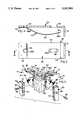
- FIG. 1is an exploded perspective view showing the improved wall panel divider system of the present invention
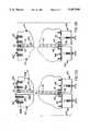
- FIGS. 2A and 2Billustrate a method of interconnecting adjacent modular wall panels in a side-by-side planar orientation utilizing the improved panel interconnection means of the present invention
- FIG. 3is a bottom view of a spring biased bracket associated with the panel interconnection means of the present invention.
- FIG. 4is a cross-sectional side view taken along lines 4--4 of FIG. 3;
- FIG. 5is an exploded perspective view showing a method of interconnecting adjacent modular wall panels in side-by-side angular orientation.
- each wall panel 10 of the present inventionis substantially identical in construction to all other panels of the divider system, and are so constructed to be readily interconnected with one or more like wall panels to form a desired spacial room configuration.
- Each wall panel 10includes a main body portion 12 having a core 14 disposed between front and rear boards 16 and 18, respectively, each of which is covered with a layer of fabric or other decorative material.
- wall panel 10is adapted to provide acoustical and visual privacy for occupants working with a workstation area.
- core 14is shown along the peripheral edges of the panel as being fabricated from wood, any suitable material is within the scope of this invention.
- Front and rear planar boards 16 and 18, respectivelyare generally rectangular in shape and are dimensioned to be slightly larger in length and height than core member 14.
- front and rear boards 16 and 18are contiguously secured to core member 14 so as to extend outwardly a predetermined distance along the entire periphery of core member 14 for defining a recessed channel 20.
- each leveller assembly 24includes an I-beam 26 having an upper transverse flange 28 adapted to be secured to a lower horizontal surface 30 of wall panel 10.
- Leveller assembly 24is illustrated as being secured to lower horizontal surface 30 by fastener screws 32 extending through bores 34 on flange 28.
- Leveller assembly 24also includes a threaded pedestal 36 adapted to engage the office floor which can be rotatably adjusted to selectively level wall panel 10 relative to the floor and/or an adjacent wall panel.
- an L-shaped bracket 40Disposed between upper transverse flange 28 and lower horizontal surface 30 of wall panel 10 is an L-shaped bracket 40 which includes a generally vertically upstanding lip portion 42.
- raceways and associated coversare employed to decoratively cover leveller assemblies 24 as well as the space, or raceway, defined between each panel 10 and the office floor.
- the raceways and associated coversare adapted to house electrical connections, telephone wires, etc. as well as provide convenient electrical outlets for the panel system.
- an upper L-shape bracket 50is provided along upper horizontal surface 48 of core 14.
- Upper bracket 50includes a downturned lip portion 51 adapted to capturingly engage an open upper end of a secondary mounting member as will be described hereinafter in greater detail. While lower bracket 40 is rigidly secured to each lower corner of wall panel 10, upper bracket 50 is secured to upper horizontal surface 48 at each corner of wall panel 10 by a pair of fasteners 52A and 52B. More particularly, fasteners 52A and 52B extend through an elongated first opening or slot 54 and a second opening 55, respectively, in upper bracket 50.
- Bores 56A and 56Bare provided in horizontal surface 48 of core 14 and preferably include a threaded cylindrical insert 58 which is adapted to accept receipt therein of fasteners 52A and 52B, respectively, upon assembly of bracket 50 onto wall panel 10.
- Elongated slot 54allows for manufacturing tolerances as well as for permitting "fore and aft" positioning to promote relatively simple alignment and assembly of upper bracket 50 onto core 14.
- the improved panel interconnection means of the present inventionalso includes biasing means located between an underside surface of L-shaped bracket 50 and upper horizontal surface 48 of core member 14.
- the biasing meansis a leaf spring 60 having a first end 62 secured (i.e., welded) to a rearward underside portion of upper bracket 50 and a second "free" end 64 which terminates slightly behind downturned lip portion 51.
- fasteners 52A and 52Bextend through elongated slotted apertures 66A and 66B, (see FIGS. 3 and 4) in leaf spring 60 which are oriented in axial alignment with slot 54 and opening 55, respectively.
- leaf spring 60is configured to coact with upper horizontal surface 48 of core 14 in a manner to cause upper bracket 50 to be upwardly displaced relative to core 14.
- leaf spring 60is adapted to normally bias upper bracket 50 such that downturned lip 51 is generally pivoted away from upper horizontal surface 48 of core 14.
- leaf spring 60normally biases bracket 50 into engagement with a lower radial shoulder formed on the head of fasteners 52A and 52B.
- fastener 52Bis threaded farther into its respective bore 56B on wall panel 10 than fastener 52A is threaded into bore 56A to maximize the upward pivoted orientation of bracket 50 relative to upper horizontal surface 48.
- upper bracket 50is pre-assembled onto wall panel 10 prior to interconnection with a secondary mounting member which is utilized in interconnecting adjacent wall panels 10.
- the exemplary secondary mounting memberis an elongated, rectangular, hollow metal frame 70 which includes a longitudinal row of slots 72 on front and rear faces thereof.
- Elongated metal frame 70has an upper open end 74 and a lower open end 76 at its opposite distal ends.
- Metal frame 70is adapted to have its opposite lateral sides secured within complimentary vertical portions of recessed channel 20 provided on the facing vertical edge surfaces of adjacent wall panels.
- lower open end 74is initially disposed over upstanding lip portion 42 of lower bracket 40.
- lower bracket 40provides means for locating metal frame 70 relative to wall panel 10.
- metal frame 70is pivoted toward wall panel 10 such that one of its lateral sides is disposed adjacent core 14 within the vertical portion of recessed channel 20.
- upper bracket 50is preferably pre-assembled onto horizontal surface 48 by partially threading fasteners 52A and 52B into bores 56A and 56B, respectively, prior to assembling metal frame 70 onto wall panel 10.
- fastener 52Ais completely threaded into insert 58 with bore 56A such that upper bracket 50 and downwardly extending lip portion 51 are urged to move downwardly against the bias of leaf spring 60 for lockingly capturing upper open end 74 of metal frame 70.
- metal frame 70can be further secured thereafter to core 14 such as by fasteners 78 extending through bores 80 so as to provide additional rigidity an support.
- Metal frame 70is installed as herebefore described to one of adjacent wall panels 10 such that when two wall panels are placed in side-by-side relation, slots 72 are exposed to allow the cantilevered mounting of workstation accessories such as desks, shelves, file cabinets, and the like. Specifically, hooks associated with support structure on the accessories are secured within slots 72.
- a opaque shield(not shown) can be installed longitudinally within metal frame 70 to inhibit light from passing through slots 72 from one work station to the next.
- metal frame 70is used for side-by-side interconnection of adjacent wall panels.
- FIGS. 2A and 2Bthe improved panel interconnection method of the present invention is more clearly illustrated.
- a first wall panel 10, having metal frame 70 mounted thereto in the manner previously described,is shown being interconnected to a substantially identical second wall panel 10'.
- the adjacent wall panels 10 and 10'are simply and quickly interconnected by inserting lower open end 76 of metal frame 70 over upstanding lip portion 42' of lower bracket 40' secured to second wall panel 10'. Thereafter, first wall panel 10 is lowered or pivoted to align the opposite lateral side of metal frame 70 within the complimentary vertical portion of the recessed channel formed on second wall panel 10'.
- upper open end 74 of metal frame 70is aligned with downwardly extending lip portion 51' of upper bracket 50' secured to second wall panel 10'.
- fasteners 52A' and 52B'are tightened for lowering upper bracket 50' downwardly until lip portion 51' securely engages upper open end 74 of frame 70, thereby clamping frame 70 against core 14' of panel 10'.
- leaf spring 60is shown as having a generally sinusoidal cambered surface 80.
- a portion of cambered surface 80engages upper horizontal surface 48 of core 14 such that when fasteners 52A and 52B are partially threaded into bores 56A and 56B, respectively, upper bracket 50 is normally displaced to a "raised” position (FIG. 2A). Subsequent tightening of fastener 52A into bore 56A tends to overcome the normal compressive biasing force of leaf spring 60 whereby lip portion 51 is generally pivoted downwardly so as to capture upper open end 74 of tubular frame 70. While the embodiment illustrated incorporates use of a leaf spring 60, it should be understood that any suitable biasing member adapted for normally biasing bracket 50 in the manner disclosed is within the fair scope of this invention.
- a method for interconnecting adjacent wall panels in an angular orientationis illustrated.
- a multi-sided corner post 100is provided to which at least two elongated metal frames 70 are mounted. More specifically, the exemplary embodiment shown in FIG. 5 illustrates utilization of four (4) metal frames 70 secured to the four (4) sides of corner post 100. Each of the frames 70 are mounted to corner post 100 by fasteners 78 extending through bores 80 in the metal frames. While in the embodiment shown, corner post 100 is wood, it will be appreciated that corner post 100 could be fabricated from other suitable materials such as a hollow metal tube and the like.
- Corner post 100is adapted to provide approximately 90° angular interconnections between adjacent wall panels. However, it is to be understood that various multi-sided corner posts can be designed to accommodate virtually any angular interconnection desired.
- adjacent wall panels 10 and 10'are individually interconnected to corner posts 100 by inserting the lower open end of metal frame 70 over the upstanding lip portion of their respective lower brackets. Thereafter, wall panel 10 is aligned relative to upper open end 74 of metal tube 70 such that metal tube 70 is disposed within the vertical portion of channel 20. Once in alignment, fastener 52A is tightened against the spring biasing of the leaf spring (not shown) so as to pivot upper bracket 50 downwardly until it securely engages upper open end 74 of frame member 70. Thereafter, second panel 10' is similarly installed in angular relation to a second metal frame 70' secured to corner post 100.
- panel 10While not shown, it will be appreciated that the upper horizontal portion of panel 10 will be enclosed with a decorative trim strip following interconnection of adjacent panels.
- the decorative trim stripis easily removed when rearrangement of wall panels 10 is desired.
- the present inventioncomprises novel features for use in a wall divider system.
- the invention as describedalso provides a unique wall panel structure for use in a modular wall panel system.
- the inventionincludes apparatus for interconnecting in side-by-side relation any two of a plurality of wall panels of the type used in modular divider systems.
- a method of interconnecting modular wall panels for subdividing an interior space into work areas having a desired spacial patternis also described.
Landscapes
- Engineering & Computer Science (AREA)
- Architecture (AREA)
- Physics & Mathematics (AREA)
- Electromagnetism (AREA)
- Civil Engineering (AREA)
- Structural Engineering (AREA)
- Finishing Walls (AREA)
Abstract
Description
Claims (31)
Priority Applications (2)
| Application Number | Priority Date | Filing Date | Title |
|---|---|---|---|
| US07/602,424US5187908A (en) | 1990-10-22 | 1990-10-22 | Modular wall panel interconnection apparatus and method |
| CA002039380ACA2039380C (en) | 1990-10-22 | 1991-03-28 | Modular wall panel interconnection apparatus and method |
Applications Claiming Priority (1)
| Application Number | Priority Date | Filing Date | Title |
|---|---|---|---|
| US07/602,424US5187908A (en) | 1990-10-22 | 1990-10-22 | Modular wall panel interconnection apparatus and method |
Publications (1)
| Publication Number | Publication Date |
|---|---|
| US5187908Atrue US5187908A (en) | 1993-02-23 |
Family
ID=24411296
Family Applications (1)
| Application Number | Title | Priority Date | Filing Date |
|---|---|---|---|
| US07/602,424Expired - Fee RelatedUS5187908A (en) | 1990-10-22 | 1990-10-22 | Modular wall panel interconnection apparatus and method |
Country Status (2)
| Country | Link |
|---|---|
| US (1) | US5187908A (en) |
| CA (1) | CA2039380C (en) |
Cited By (27)
| Publication number | Priority date | Publication date | Assignee | Title |
|---|---|---|---|---|
| US5664380A (en)* | 1995-07-12 | 1997-09-09 | Hsueh; Jen Shiung | Partition frame structure |
| WO1997039200A1 (en)* | 1996-04-12 | 1997-10-23 | Max Girbinger | Partition wall system for commercial premises |
| US5740650A (en)* | 1994-12-30 | 1998-04-21 | Steelcase Inc. | Partition system |
| US5784843A (en)* | 1994-12-30 | 1998-07-28 | Steelcase Inc. | Integrated prefabricated furniture system for fitting-out open plan building space |
| US6000179A (en)* | 1996-12-13 | 1999-12-14 | Steelcase Inc. | Stacking panel and off-module panel connections |
| US6088980A (en)* | 1997-12-24 | 2000-07-18 | L & P Property Management Company | Space divider system |
| US6112472A (en)* | 1998-09-14 | 2000-09-05 | Steelcase Development Inc. | Integrated furniture system including overhead framework system and partition system |
| US6115977A (en)* | 1998-09-11 | 2000-09-12 | Krueger International, Inc. | Knock-down panel partition system |
| US6158179A (en)* | 1998-03-10 | 2000-12-12 | Steelcase Development Inc. | Overhead structures for wall system |
| US6202381B1 (en) | 1996-06-07 | 2001-03-20 | Herman Miller, Inc. | Method for reconfiguring a wall panel system |
| US6223485B1 (en)* | 1996-06-07 | 2001-05-01 | Herman Miller, Inc. | Wall panel system |
| US6336298B1 (en)* | 2000-01-28 | 2002-01-08 | Arthur Chou | Partition composition |
| US20030070377A1 (en)* | 1996-12-24 | 2003-04-17 | Waalkes Michael L. | Knock-down portable partition system |
| US6712118B2 (en)* | 2001-10-11 | 2004-03-30 | Jeffrey Mark Nussdorf | Portable exhibition frame assembly |
| US6729085B2 (en) | 2001-02-09 | 2004-05-04 | Herman Miller, Inc. | Wall panel system |
| US20040154267A1 (en)* | 2003-01-31 | 2004-08-12 | Burken David J. | Base assembly for wall panel construction |
| US20060162268A1 (en)* | 2005-01-13 | 2006-07-27 | Steelcase Development Corporation | Partition panel system and method |
| US7461484B2 (en) | 2002-02-15 | 2008-12-09 | Steelcase Inc. | Customizable partition system |
| US20110232850A1 (en)* | 2010-03-24 | 2011-09-29 | Bellcomb Technologies Incorporated | Modular panel assembly |
| WO2013067037A1 (en)* | 2011-10-31 | 2013-05-10 | Bellcomb, Inc. | Tool-less modular panel system |
| US8887459B2 (en) | 2012-05-19 | 2014-11-18 | Virginia Tech Intellectual Properties, Inc. | Modular wall assembly system |
| WO2020096520A1 (en)* | 2018-11-09 | 2020-05-14 | Ikea Supply Ag | A room divider system and connector for a room divider system |
| US20200217067A1 (en)* | 2019-01-08 | 2020-07-09 | EverBlock Systems, LLC | Modular Wall Panels and System |
| CN113167070A (en)* | 2018-11-09 | 2021-07-23 | 宜家供应有限公司 | Room partitioning system and connector for room partitioning system |
| US11174632B2 (en)* | 2019-01-08 | 2021-11-16 | Versare Solutions, Llc | Modular wall panels and system |
| JP2023133886A (en)* | 2022-03-14 | 2023-09-27 | 株式会社ニチベイ | Partition, and connector for partition |
| US11859379B2 (en)* | 2018-08-31 | 2024-01-02 | Awi Licensing Llc | Collapsible structural frame system for a sheet-like building material |
Citations (43)
| Publication number | Priority date | Publication date | Assignee | Title |
|---|---|---|---|---|
| US1238215A (en)* | 1916-10-05 | 1917-08-28 | Albert O Terrell | Metallic cabinet. |
| US1487856A (en)* | 1919-06-27 | 1924-03-25 | Hauserman Co E F | Metallic bin, shelving, and the like |
| US2326507A (en)* | 1942-03-16 | 1943-08-10 | Grand Rapids Store Equip Co | Furniture construction |
| US2424217A (en)* | 1941-03-12 | 1947-07-22 | Lyon Metal Products Inc | Sheet metal storage cabinet |
| US2483606A (en)* | 1946-10-25 | 1949-10-04 | Medart Company | Knockdown utility cabinet |
| US2626198A (en)* | 1948-10-18 | 1953-01-20 | Grand Rapids Store Equip Co | Store wall furniture |
| US2643170A (en)* | 1950-07-10 | 1953-06-23 | Grand Rapids Store Equip Co | Store wall furniture |
| US2827955A (en)* | 1956-03-29 | 1958-03-25 | Albert B Hurley | Folding motion picture projection screen |
| US3178245A (en)* | 1962-10-31 | 1965-04-13 | Kenneth S Morioka | Modular cabinet structure |
| US3228157A (en)* | 1964-04-13 | 1966-01-11 | Movable Walls Corp | Movable partitions |
| US3327440A (en)* | 1962-04-10 | 1967-06-27 | Katherine M Griffin | Partition construction with vertically adjustable floor-engaging foot |
| US3341270A (en)* | 1965-10-21 | 1967-09-12 | Art Metal Inc | Office equipment system and components thereof |
| US3377763A (en)* | 1965-11-08 | 1968-04-16 | Nat Lock Co | Shear clamp |
| US3378320A (en)* | 1964-07-24 | 1968-04-16 | Westinghouse Electric Corp | Modular constructed enclosure for mounting equipment therein |
| US3428108A (en)* | 1967-12-20 | 1969-02-18 | Singer Partitions Inc | Panel connector |
| US3788378A (en)* | 1971-07-16 | 1974-01-29 | Osf Ind Ltd | Floor area divider |
| US3846002A (en)* | 1972-03-10 | 1974-11-05 | Floetotto | Building unit for furniture |
| US3871435A (en)* | 1971-04-01 | 1975-03-18 | Reflector Hardware Corp | Modular room divider |
| US3926243A (en)* | 1974-02-11 | 1975-12-16 | Goodyear Aerospace Corp | Cargo container latches |
| US3948581A (en)* | 1974-07-02 | 1976-04-06 | Helman Philip L | Knockdown furniture assemblies |
| US4055373A (en)* | 1974-10-04 | 1977-10-25 | Inbauproduct Innenausbausysteme Gmbh & Co., Kg | Furniture construction system |
| US4060294A (en)* | 1975-09-22 | 1977-11-29 | Haworth Mfg., Inc. | Wall panel with prewired power system |
| US4100709A (en)* | 1976-09-30 | 1978-07-18 | Harter Corporation | Frame construction for a divider wall |
| US4104838A (en)* | 1977-05-17 | 1978-08-08 | Gf Business Equipment, Inc. | Portable wall assembly |
| US4116509A (en)* | 1976-07-02 | 1978-09-26 | R. C. Smith Company | Modular furniture unit for hospital pharmacies or the like |
| US4121645A (en)* | 1977-05-06 | 1978-10-24 | Joseph Henry Behr | Room divider panel assembly |
| US4166332A (en)* | 1976-06-01 | 1979-09-04 | Package Exhibit Programs, Inc. | Portable display apparatus |
| US4206955A (en)* | 1978-08-01 | 1980-06-10 | Cooper Jack M | Closet storage unit |
| US4232724A (en)* | 1978-10-23 | 1980-11-11 | Nightingale Industries Limited | Modular partition |
| US4250676A (en)* | 1978-09-19 | 1981-02-17 | Knoll International Inc. | Panel interconnecting and upholstery-retaining connection for a tubular frame |
| US4344475A (en)* | 1976-04-05 | 1982-08-17 | Frey Fred J | Office partition interconnector assembly |
| US4416093A (en)* | 1979-06-11 | 1983-11-22 | Litton Business Systems, Inc. | Panel system interconnecting means |
| US4516619A (en)* | 1982-08-16 | 1985-05-14 | Hon Industries, Inc. | Partition system and connectors therefor |
| US4567698A (en)* | 1983-12-13 | 1986-02-04 | Knoll International, Inc. | Space divider system |
| US4603530A (en)* | 1981-04-07 | 1986-08-05 | Karl Glockenstein | Wall element |
| US4637177A (en)* | 1983-07-29 | 1987-01-20 | Long Dennis L | Modular unit adapted for office use |
| US4644993A (en)* | 1984-03-07 | 1987-02-24 | John Cooper | Modular panel system |
| US4733841A (en)* | 1986-08-08 | 1988-03-29 | Haworth, Inc. | Hanger bracket for cabinet |
| US4821788A (en)* | 1988-04-18 | 1989-04-18 | Media/Graphics, Inc. | Locking system for display panels |
| US4841699A (en)* | 1988-04-05 | 1989-06-27 | Haworth, Inc. | Wall panel with accessible interior channels for laying in of cables |
| US4860812A (en)* | 1988-08-31 | 1989-08-29 | Gf Furniture Systems, Inc. | Connecting means for partition systems |
| US4904105A (en)* | 1988-11-03 | 1990-02-27 | Myers Robert E | Tensioned grating fastener |
| US5004371A (en)* | 1988-03-04 | 1991-04-02 | The Gunlocke Co. | Office partition, panel-to-panel quick-locking mechanism |
- 1990
- 1990-10-22USUS07/602,424patent/US5187908A/ennot_activeExpired - Fee Related
- 1991
- 1991-03-28CACA002039380Apatent/CA2039380C/ennot_activeExpired - Fee Related
Patent Citations (43)
| Publication number | Priority date | Publication date | Assignee | Title |
|---|---|---|---|---|
| US1238215A (en)* | 1916-10-05 | 1917-08-28 | Albert O Terrell | Metallic cabinet. |
| US1487856A (en)* | 1919-06-27 | 1924-03-25 | Hauserman Co E F | Metallic bin, shelving, and the like |
| US2424217A (en)* | 1941-03-12 | 1947-07-22 | Lyon Metal Products Inc | Sheet metal storage cabinet |
| US2326507A (en)* | 1942-03-16 | 1943-08-10 | Grand Rapids Store Equip Co | Furniture construction |
| US2483606A (en)* | 1946-10-25 | 1949-10-04 | Medart Company | Knockdown utility cabinet |
| US2626198A (en)* | 1948-10-18 | 1953-01-20 | Grand Rapids Store Equip Co | Store wall furniture |
| US2643170A (en)* | 1950-07-10 | 1953-06-23 | Grand Rapids Store Equip Co | Store wall furniture |
| US2827955A (en)* | 1956-03-29 | 1958-03-25 | Albert B Hurley | Folding motion picture projection screen |
| US3327440A (en)* | 1962-04-10 | 1967-06-27 | Katherine M Griffin | Partition construction with vertically adjustable floor-engaging foot |
| US3178245A (en)* | 1962-10-31 | 1965-04-13 | Kenneth S Morioka | Modular cabinet structure |
| US3228157A (en)* | 1964-04-13 | 1966-01-11 | Movable Walls Corp | Movable partitions |
| US3378320A (en)* | 1964-07-24 | 1968-04-16 | Westinghouse Electric Corp | Modular constructed enclosure for mounting equipment therein |
| US3341270A (en)* | 1965-10-21 | 1967-09-12 | Art Metal Inc | Office equipment system and components thereof |
| US3377763A (en)* | 1965-11-08 | 1968-04-16 | Nat Lock Co | Shear clamp |
| US3428108A (en)* | 1967-12-20 | 1969-02-18 | Singer Partitions Inc | Panel connector |
| US3871435A (en)* | 1971-04-01 | 1975-03-18 | Reflector Hardware Corp | Modular room divider |
| US3788378A (en)* | 1971-07-16 | 1974-01-29 | Osf Ind Ltd | Floor area divider |
| US3846002A (en)* | 1972-03-10 | 1974-11-05 | Floetotto | Building unit for furniture |
| US3926243A (en)* | 1974-02-11 | 1975-12-16 | Goodyear Aerospace Corp | Cargo container latches |
| US3948581A (en)* | 1974-07-02 | 1976-04-06 | Helman Philip L | Knockdown furniture assemblies |
| US4055373A (en)* | 1974-10-04 | 1977-10-25 | Inbauproduct Innenausbausysteme Gmbh & Co., Kg | Furniture construction system |
| US4060294A (en)* | 1975-09-22 | 1977-11-29 | Haworth Mfg., Inc. | Wall panel with prewired power system |
| US4344475A (en)* | 1976-04-05 | 1982-08-17 | Frey Fred J | Office partition interconnector assembly |
| US4166332A (en)* | 1976-06-01 | 1979-09-04 | Package Exhibit Programs, Inc. | Portable display apparatus |
| US4116509A (en)* | 1976-07-02 | 1978-09-26 | R. C. Smith Company | Modular furniture unit for hospital pharmacies or the like |
| US4100709A (en)* | 1976-09-30 | 1978-07-18 | Harter Corporation | Frame construction for a divider wall |
| US4121645A (en)* | 1977-05-06 | 1978-10-24 | Joseph Henry Behr | Room divider panel assembly |
| US4104838A (en)* | 1977-05-17 | 1978-08-08 | Gf Business Equipment, Inc. | Portable wall assembly |
| US4206955A (en)* | 1978-08-01 | 1980-06-10 | Cooper Jack M | Closet storage unit |
| US4250676A (en)* | 1978-09-19 | 1981-02-17 | Knoll International Inc. | Panel interconnecting and upholstery-retaining connection for a tubular frame |
| US4232724A (en)* | 1978-10-23 | 1980-11-11 | Nightingale Industries Limited | Modular partition |
| US4416093A (en)* | 1979-06-11 | 1983-11-22 | Litton Business Systems, Inc. | Panel system interconnecting means |
| US4603530A (en)* | 1981-04-07 | 1986-08-05 | Karl Glockenstein | Wall element |
| US4516619A (en)* | 1982-08-16 | 1985-05-14 | Hon Industries, Inc. | Partition system and connectors therefor |
| US4637177A (en)* | 1983-07-29 | 1987-01-20 | Long Dennis L | Modular unit adapted for office use |
| US4567698A (en)* | 1983-12-13 | 1986-02-04 | Knoll International, Inc. | Space divider system |
| US4644993A (en)* | 1984-03-07 | 1987-02-24 | John Cooper | Modular panel system |
| US4733841A (en)* | 1986-08-08 | 1988-03-29 | Haworth, Inc. | Hanger bracket for cabinet |
| US5004371A (en)* | 1988-03-04 | 1991-04-02 | The Gunlocke Co. | Office partition, panel-to-panel quick-locking mechanism |
| US4841699A (en)* | 1988-04-05 | 1989-06-27 | Haworth, Inc. | Wall panel with accessible interior channels for laying in of cables |
| US4821788A (en)* | 1988-04-18 | 1989-04-18 | Media/Graphics, Inc. | Locking system for display panels |
| US4860812A (en)* | 1988-08-31 | 1989-08-29 | Gf Furniture Systems, Inc. | Connecting means for partition systems |
| US4904105A (en)* | 1988-11-03 | 1990-02-27 | Myers Robert E | Tensioned grating fastener |
Non-Patent Citations (2)
| Title |
|---|
| Business Interiors article entitled "Sneak Preview: Rose Johnson introduces RJPlus", Sep.-Oct. 1989. |
| Business Interiors article entitled Sneak Preview: Rose Johnson introduces RJPlus , Sep. Oct. 1989.* |
Cited By (55)
| Publication number | Priority date | Publication date | Assignee | Title |
|---|---|---|---|---|
| US6134845A (en) | 1994-12-30 | 2000-10-24 | Steelcase Development Inc. | Partitions with connecting structure |
| US6397532B1 (en) | 1994-12-30 | 2002-06-04 | Steelcase Development Corporation | Partition frame construction having wireways and off-module connection |
| US5740650A (en)* | 1994-12-30 | 1998-04-21 | Steelcase Inc. | Partition system |
| US5746034A (en)* | 1994-12-30 | 1998-05-05 | Steelcase Inc. | Partition system |
| US5746035A (en)* | 1994-12-30 | 1998-05-05 | Steelcase Inc. | Partition system |
| US5784843A (en)* | 1994-12-30 | 1998-07-28 | Steelcase Inc. | Integrated prefabricated furniture system for fitting-out open plan building space |
| US5809708A (en)* | 1994-12-30 | 1998-09-22 | Steelcase Inc. | Integrated prefabricated furniture system for fitting-out open plan building space |
| US6928785B2 (en) | 1994-12-30 | 2005-08-16 | Steelcase Development Corporation | Method of connecting partition panels |
| US6167676B1 (en) | 1994-12-30 | 2001-01-02 | Steelcase Development, Inc. | Method of connecting partitions |
| US6134852A (en) | 1994-12-30 | 2000-10-24 | Steelcase Development Inc. | Partition frame construction having wireways and off-module connection |
| US5664380A (en)* | 1995-07-12 | 1997-09-09 | Hsueh; Jen Shiung | Partition frame structure |
| WO1997039200A1 (en)* | 1996-04-12 | 1997-10-23 | Max Girbinger | Partition wall system for commercial premises |
| US6339907B1 (en) | 1996-06-07 | 2002-01-22 | Herman Miller, Inc. | System of wall panels |
| US6223485B1 (en)* | 1996-06-07 | 2001-05-01 | Herman Miller, Inc. | Wall panel system |
| US6393783B2 (en) | 1996-06-07 | 2002-05-28 | Herman Miller, Inc. | Wall panel |
| US6301847B1 (en) | 1996-06-07 | 2001-10-16 | Herman Miller, Inc. | Wall panel |
| US6202381B1 (en) | 1996-06-07 | 2001-03-20 | Herman Miller, Inc. | Method for reconfiguring a wall panel system |
| US6000179A (en)* | 1996-12-13 | 1999-12-14 | Steelcase Inc. | Stacking panel and off-module panel connections |
| US7565772B2 (en)* | 1996-12-24 | 2009-07-28 | Steelcase, Inc. | Knock-down portable partition system |
| US20030070377A1 (en)* | 1996-12-24 | 2003-04-17 | Waalkes Michael L. | Knock-down portable partition system |
| US20050144855A1 (en)* | 1996-12-24 | 2005-07-07 | Waalkes Michael L. | Knock-down portable partition system |
| US6910306B2 (en)* | 1996-12-24 | 2005-06-28 | Steelcase Development Corporation | Knock-down portable partition system |
| US6088980A (en)* | 1997-12-24 | 2000-07-18 | L & P Property Management Company | Space divider system |
| US6158179A (en)* | 1998-03-10 | 2000-12-12 | Steelcase Development Inc. | Overhead structures for wall system |
| US6131347A (en)* | 1998-09-11 | 2000-10-17 | Krueger International, Inc. | Reconfigurable wall panel partition system |
| US6115977A (en)* | 1998-09-11 | 2000-09-12 | Krueger International, Inc. | Knock-down panel partition system |
| US6397533B1 (en) | 1998-09-11 | 2002-06-04 | Krueger International, Inc. | Tile and mounting arrangement for a wall panel system |
| US6112472A (en)* | 1998-09-14 | 2000-09-05 | Steelcase Development Inc. | Integrated furniture system including overhead framework system and partition system |
| US6336298B1 (en)* | 2000-01-28 | 2002-01-08 | Arthur Chou | Partition composition |
| US6729085B2 (en) | 2001-02-09 | 2004-05-04 | Herman Miller, Inc. | Wall panel system |
| US6820388B2 (en) | 2001-02-09 | 2004-11-23 | Herman Miller, Inc. | Stackable wall panel assembly and connector therefor |
| US6712118B2 (en)* | 2001-10-11 | 2004-03-30 | Jeffrey Mark Nussdorf | Portable exhibition frame assembly |
| US7461484B2 (en) | 2002-02-15 | 2008-12-09 | Steelcase Inc. | Customizable partition system |
| US6865853B2 (en)* | 2003-01-31 | 2005-03-15 | Hon Technology Inc. | Base assembly for wall panel construction |
| US20040154267A1 (en)* | 2003-01-31 | 2004-08-12 | Burken David J. | Base assembly for wall panel construction |
| US20060162268A1 (en)* | 2005-01-13 | 2006-07-27 | Steelcase Development Corporation | Partition panel system and method |
| US7603821B2 (en)* | 2005-01-13 | 2009-10-20 | Steelcase Inc. | Partition panel system and method |
| US20100064597A1 (en)* | 2005-01-13 | 2010-03-18 | Eberlein David C | Partition panel system and method |
| US7818932B2 (en) | 2005-01-13 | 2010-10-26 | Steelcase Inc. | Partition panel system and method |
| US20110068242A1 (en)* | 2005-01-13 | 2011-03-24 | Eberlein David C | Partition panel system and mounting bracket assembly therefor |
| US20110232850A1 (en)* | 2010-03-24 | 2011-09-29 | Bellcomb Technologies Incorporated | Modular panel assembly |
| US8196639B2 (en) | 2010-03-24 | 2012-06-12 | Bellcomb Technologies Incorporated | Modular panel assembly |
| WO2013067037A1 (en)* | 2011-10-31 | 2013-05-10 | Bellcomb, Inc. | Tool-less modular panel system |
| US8887459B2 (en) | 2012-05-19 | 2014-11-18 | Virginia Tech Intellectual Properties, Inc. | Modular wall assembly system |
| US11859379B2 (en)* | 2018-08-31 | 2024-01-02 | Awi Licensing Llc | Collapsible structural frame system for a sheet-like building material |
| WO2020096520A1 (en)* | 2018-11-09 | 2020-05-14 | Ikea Supply Ag | A room divider system and connector for a room divider system |
| CN113167070A (en)* | 2018-11-09 | 2021-07-23 | 宜家供应有限公司 | Room partitioning system and connector for room partitioning system |
| US20210396007A1 (en)* | 2018-11-09 | 2021-12-23 | Ikea Supply Ag | Room divider system and connector for a room divider system |
| CN113167070B (en)* | 2018-11-09 | 2023-12-08 | 宜家供应有限公司 | Room divider system and connector for room divider system |
| US12031324B2 (en)* | 2018-11-09 | 2024-07-09 | Ikea Supply Ag | Room divider system and connector for a room divider system |
| US20200217067A1 (en)* | 2019-01-08 | 2020-07-09 | EverBlock Systems, LLC | Modular Wall Panels and System |
| US11085182B2 (en)* | 2019-01-08 | 2021-08-10 | Versare Solutions, Llc | Modular wall panels and system |
| US11174632B2 (en)* | 2019-01-08 | 2021-11-16 | Versare Solutions, Llc | Modular wall panels and system |
| US11661736B2 (en) | 2019-01-08 | 2023-05-30 | Versare Solutions Llc | Modular wall panels and system |
| JP2023133886A (en)* | 2022-03-14 | 2023-09-27 | 株式会社ニチベイ | Partition, and connector for partition |
Also Published As
| Publication number | Publication date |
|---|---|
| CA2039380C (en) | 1995-02-28 |
Similar Documents
| Publication | Publication Date | Title |
|---|---|---|
| US5187908A (en) | Modular wall panel interconnection apparatus and method | |
| US5175969A (en) | Partition panel | |
| US6425219B1 (en) | Modular partition system | |
| US6711871B2 (en) | Wall panel with off-module components | |
| US6397533B1 (en) | Tile and mounting arrangement for a wall panel system | |
| US6442909B2 (en) | Knock-down portable partition system | |
| EP0557092B1 (en) | Work space partition system | |
| US4876835A (en) | Work space management system | |
| EP0479330B1 (en) | Work space management system | |
| US5899035A (en) | Knock-down portable partition system | |
| CA2261931C (en) | Wall panel system | |
| US7818932B2 (en) | Partition panel system and method | |
| US5746034A (en) | Partition system | |
| US6173545B1 (en) | Connector for partition system | |
| EP0133269A2 (en) | Locking mechanism for an office panel system | |
| US20140261100A1 (en) | Office furniture system | |
| WO1998028503A1 (en) | Knock-down portable partition system | |
| US6230459B1 (en) | Wall start for panel systems | |
| US6178702B1 (en) | Flexible light seal for partition systems | |
| CA2539496C (en) | Knock-down panel partition system |
Legal Events
| Date | Code | Title | Description |
|---|---|---|---|
| AS | Assignment | Owner name:LA-Z BOY CHAIR COMPANY, A CORP. OF MICHIGAN, MICHI Free format text:ASSIGNMENT OF ASSIGNORS INTEREST.;ASSIGNOR:LOSENSKY, CHARLES I.;REEL/FRAME:005488/0885 Effective date:19901011 | |
| FEPP | Fee payment procedure | Free format text:PAYOR NUMBER ASSIGNED (ORIGINAL EVENT CODE: ASPN); ENTITY STATUS OF PATENT OWNER: LARGE ENTITY | |
| FPAY | Fee payment | Year of fee payment:4 | |
| AS | Assignment | Owner name:LA-Z-BOY INCORPORATED, MICHIGAN Free format text:CHANGE OF NAME;ASSIGNOR:LA-Z-BOY CHAIR COMPANY;REEL/FRAME:008167/0972 Effective date:19960816 | |
| REMI | Maintenance fee reminder mailed | ||
| LAPS | Lapse for failure to pay maintenance fees | ||
| FP | Lapsed due to failure to pay maintenance fee | Effective date:20010223 | |
| AS | Assignment | Owner name:WACHOVIA CAPITAL FINANCE CORPORATION (CENTRAL), AS Free format text:SECURITY AGREEMENT;ASSIGNORS:LA-Z-BOY INCORPORATED;KINCAID FURNITURE COMPANY, INCORPORATED;ENGLAND, INC.;AND OTHERS;REEL/FRAME:020487/0199 Effective date:20080206 | |
| STCH | Information on status: patent discontinuation | Free format text:PATENT EXPIRED DUE TO NONPAYMENT OF MAINTENANCE FEES UNDER 37 CFR 1.362 |