US5186793A - Oxygen concentrator utilizing electrochemical cell - Google Patents
Oxygen concentrator utilizing electrochemical cellDownload PDFInfo
- Publication number
- US5186793A US5186793AUS07/636,487US63648790AUS5186793AUS 5186793 AUS5186793 AUS 5186793AUS 63648790 AUS63648790 AUS 63648790AUS 5186793 AUS5186793 AUS 5186793A
- Authority
- US
- United States
- Prior art keywords
- gases
- oxygen
- passageway
- generator
- housing
- Prior art date
- Legal status (The legal status is an assumption and is not a legal conclusion. Google has not performed a legal analysis and makes no representation as to the accuracy of the status listed.)
- Expired - Lifetime
Links
- 239000001301oxygenSubstances0.000titleclaimsabstractdescription203
- 229910052760oxygenInorganic materials0.000titleclaimsabstractdescription203
- QVGXLLKOCUKJST-UHFFFAOYSA-Natomic oxygenChemical compound[O]QVGXLLKOCUKJST-UHFFFAOYSA-N0.000titleclaimsabstractdescription194
- 238000003487electrochemical reactionMethods0.000claimsabstractdescription7
- 239000007789gasSubstances0.000claimsdescription116
- 238000000034methodMethods0.000claimsdescription36
- 239000000463materialSubstances0.000claimsdescription31
- 239000000203mixtureSubstances0.000claimsdescription23
- 238000002156mixingMethods0.000claimsdescription17
- 238000010438heat treatmentMethods0.000claimsdescription16
- 230000007704transitionEffects0.000claimsdescription16
- 230000005855radiationEffects0.000claimsdescription11
- 238000009413insulationMethods0.000claimsdescription10
- 238000004519manufacturing processMethods0.000claimsdescription9
- 238000012546transferMethods0.000claimsdescription4
- 229910000323aluminium silicateInorganic materials0.000claimsdescription3
- HNPSIPDUKPIQMN-UHFFFAOYSA-Ndioxosilane;oxo(oxoalumanyloxy)alumaneChemical compoundO=[Si]=O.O=[Al]O[Al]=OHNPSIPDUKPIQMN-UHFFFAOYSA-N0.000claimsdescription3
- 238000006243chemical reactionMethods0.000claimsdescription2
- 238000000605extractionMethods0.000claims4
- 238000006073displacement reactionMethods0.000claims1
- 239000003570airSubstances0.000description125
- MCMNRKCIXSYSNV-UHFFFAOYSA-NZirconium dioxideChemical compoundO=[Zr]=OMCMNRKCIXSYSNV-UHFFFAOYSA-N0.000description22
- 239000003792electrolyteSubstances0.000description20
- 230000008901benefitEffects0.000description16
- 239000000919ceramicSubstances0.000description14
- BASFCYQUMIYNBI-UHFFFAOYSA-NplatinumChemical compound[Pt]BASFCYQUMIYNBI-UHFFFAOYSA-N0.000description14
- 238000013461designMethods0.000description13
- MYMOFIZGZYHOMD-UHFFFAOYSA-NDioxygenChemical compoundO=OMYMOFIZGZYHOMD-UHFFFAOYSA-N0.000description12
- 229910052751metalInorganic materials0.000description11
- 239000002184metalSubstances0.000description11
- IJGRMHOSHXDMSA-UHFFFAOYSA-NAtomic nitrogenChemical compoundN#NIJGRMHOSHXDMSA-UHFFFAOYSA-N0.000description8
- 239000012080ambient airSubstances0.000description8
- BQCADISMDOOEFD-UHFFFAOYSA-NSilverChemical compound[Ag]BQCADISMDOOEFD-UHFFFAOYSA-N0.000description7
- -1oxygen ionsChemical class0.000description7
- 230000008569processEffects0.000description7
- 229910052709silverInorganic materials0.000description7
- 239000004332silverSubstances0.000description7
- 229910052712strontiumInorganic materials0.000description7
- CIOAGBVUUVVLOB-UHFFFAOYSA-Nstrontium atomChemical compound[Sr]CIOAGBVUUVVLOB-UHFFFAOYSA-N0.000description7
- KDLHZDBZIXYQEI-UHFFFAOYSA-NPalladiumChemical compound[Pd]KDLHZDBZIXYQEI-UHFFFAOYSA-N0.000description6
- BQENXCOZCUHKRE-UHFFFAOYSA-N[La+3].[La+3].[O-][Mn]([O-])=O.[O-][Mn]([O-])=O.[O-][Mn]([O-])=OChemical group[La+3].[La+3].[O-][Mn]([O-])=O.[O-][Mn]([O-])=O.[O-][Mn]([O-])=OBQENXCOZCUHKRE-UHFFFAOYSA-N0.000description6
- 239000002019doping agentSubstances0.000description6
- SWELZOZIOHGSPA-UHFFFAOYSA-Npalladium silverChemical compound[Pd].[Ag]SWELZOZIOHGSPA-UHFFFAOYSA-N0.000description6
- 229910052697platinumInorganic materials0.000description6
- PXHVJJICTQNCMI-UHFFFAOYSA-NNickelChemical compound[Ni]PXHVJJICTQNCMI-UHFFFAOYSA-N0.000description4
- 229910001882dioxygenInorganic materials0.000description4
- 239000000835fiberSubstances0.000description4
- 229910052757nitrogenInorganic materials0.000description4
- 238000005245sinteringMethods0.000description4
- 239000007784solid electrolyteSubstances0.000description4
- 239000007921spraySubstances0.000description4
- 238000007740vapor depositionMethods0.000description4
- OYPRJOBELJOOCE-UHFFFAOYSA-NCalciumChemical compound[Ca]OYPRJOBELJOOCE-UHFFFAOYSA-N0.000description3
- FYYHWMGAXLPEAU-UHFFFAOYSA-NMagnesiumChemical compound[Mg]FYYHWMGAXLPEAU-UHFFFAOYSA-N0.000description3
- 229910001252Pd alloyInorganic materials0.000description3
- 229910002084calcia-stabilized zirconiaInorganic materials0.000description3
- 229910052791calciumInorganic materials0.000description3
- 239000011575calciumSubstances0.000description3
- NFYLSJDPENHSBT-UHFFFAOYSA-Nchromium(3+);lanthanum(3+);oxygen(2-)Chemical compound[O-2].[O-2].[O-2].[Cr+3].[La+3]NFYLSJDPENHSBT-UHFFFAOYSA-N0.000description3
- 239000007772electrode materialSubstances0.000description3
- 229910052749magnesiumInorganic materials0.000description3
- 239000011777magnesiumSubstances0.000description3
- 238000002844meltingMethods0.000description3
- 230000008018meltingEffects0.000description3
- 229910052763palladiumInorganic materials0.000description3
- 239000007787solidSubstances0.000description3
- 238000001179sorption measurementMethods0.000description3
- XEEYBQQBJWHFJM-UHFFFAOYSA-NIronChemical compound[Fe]XEEYBQQBJWHFJM-UHFFFAOYSA-N0.000description2
- 239000000853adhesiveSubstances0.000description2
- 230000001070adhesive effectEffects0.000description2
- 230000004075alterationEffects0.000description2
- 230000004888barrier functionEffects0.000description2
- 230000015572biosynthetic processEffects0.000description2
- 229910010293ceramic materialInorganic materials0.000description2
- 239000012141concentrateSubstances0.000description2
- 230000002950deficientEffects0.000description2
- PCHJSUWPFVWCPO-UHFFFAOYSA-NgoldChemical compound[Au]PCHJSUWPFVWCPO-UHFFFAOYSA-N0.000description2
- 229910052737goldInorganic materials0.000description2
- 239000010931goldSubstances0.000description2
- 229910001026inconelInorganic materials0.000description2
- 230000007246mechanismEffects0.000description2
- 238000012986modificationMethods0.000description2
- 230000004048modificationEffects0.000description2
- 229910052759nickelInorganic materials0.000description2
- 150000002926oxygenChemical class0.000description2
- 230000029058respiratory gaseous exchangeEffects0.000description2
- 238000004544sputter depositionMethods0.000description2
- 229910002969CaMnO3Inorganic materials0.000description1
- VYZAMTAEIAYCRO-UHFFFAOYSA-NChromiumChemical compound[Cr]VYZAMTAEIAYCRO-UHFFFAOYSA-N0.000description1
- RYGMFSIKBFXOCR-UHFFFAOYSA-NCopperChemical compound[Cu]RYGMFSIKBFXOCR-UHFFFAOYSA-N0.000description1
- 229910002254LaCoO3Inorganic materials0.000description1
- 229910002328LaMnO3Inorganic materials0.000description1
- 229910002340LaNiO3Inorganic materials0.000description1
- 229910001260Pt alloyInorganic materials0.000description1
- PNEYBMLMFCGWSK-UHFFFAOYSA-Naluminium oxideInorganic materials[O-2].[O-2].[O-2].[Al+3].[Al+3]PNEYBMLMFCGWSK-UHFFFAOYSA-N0.000description1
- 230000000712assemblyEffects0.000description1
- 238000000429assemblyMethods0.000description1
- 230000004323axial lengthEffects0.000description1
- 235000012255calcium oxideNutrition0.000description1
- 239000000292calcium oxideSubstances0.000description1
- 238000005229chemical vapour depositionMethods0.000description1
- 229910052804chromiumInorganic materials0.000description1
- 239000011651chromiumSubstances0.000description1
- 238000000576coating methodMethods0.000description1
- 229910017052cobaltInorganic materials0.000description1
- 239000010941cobaltSubstances0.000description1
- GUTLYIVDDKVIGB-UHFFFAOYSA-Ncobalt atomChemical compound[Co]GUTLYIVDDKVIGB-UHFFFAOYSA-N0.000description1
- 229910052802copperInorganic materials0.000description1
- 239000010949copperSubstances0.000description1
- 230000007812deficiencyEffects0.000description1
- 238000000280densificationMethods0.000description1
- 238000000151depositionMethods0.000description1
- 230000000694effectsEffects0.000description1
- 238000003411electrode reactionMethods0.000description1
- 239000002001electrolyte materialSubstances0.000description1
- 230000008030eliminationEffects0.000description1
- 238000003379elimination reactionMethods0.000description1
- 238000011156evaluationMethods0.000description1
- 239000010419fine particleSubstances0.000description1
- 239000012530fluidSubstances0.000description1
- 239000012774insulation materialSubstances0.000description1
- 229910052742ironInorganic materials0.000description1
- 210000004072lungAnatomy0.000description1
- 238000012423maintenanceMethods0.000description1
- WPBNNNQJVZRUHP-UHFFFAOYSA-Lmanganese(2+);methyl n-[[2-(methoxycarbonylcarbamothioylamino)phenyl]carbamothioyl]carbamate;n-[2-(sulfidocarbothioylamino)ethyl]carbamodithioateChemical compound[Mn+2].[S-]C(=S)NCCNC([S-])=S.COC(=O)NC(=S)NC1=CC=CC=C1NC(=S)NC(=O)OCWPBNNNQJVZRUHP-UHFFFAOYSA-L0.000description1
- 229910000473manganese(VI) oxideInorganic materials0.000description1
- 230000000873masking effectEffects0.000description1
- 239000000155meltSubstances0.000description1
- 150000002739metalsChemical class0.000description1
- 229910000623nickel–chromium alloyInorganic materials0.000description1
- 230000000474nursing effectEffects0.000description1
- 230000003647oxidationEffects0.000description1
- 238000007254oxidation reactionMethods0.000description1
- 239000002245particleSubstances0.000description1
- 239000011148porous materialSubstances0.000description1
- 239000000843powderSubstances0.000description1
- 238000010926purgeMethods0.000description1
- 229910052761rare earth metalInorganic materials0.000description1
- 229910001404rare earth metal oxideInorganic materials0.000description1
- 230000009467reductionEffects0.000description1
- 230000000630rising effectEffects0.000description1
- 238000000926separation methodMethods0.000description1
- 229910010271silicon carbideInorganic materials0.000description1
- 239000002002slurrySubstances0.000description1
- 125000006850spacer groupChemical group0.000description1
- 238000005507sprayingMethods0.000description1
- 229910002076stabilized zirconiaInorganic materials0.000description1
- 239000013589supplementSubstances0.000description1
- 239000002699waste materialSubstances0.000description1
- 229910001233yttria-stabilized zirconiaInorganic materials0.000description1
Images


Classifications
- C—CHEMISTRY; METALLURGY
- C01—INORGANIC CHEMISTRY
- C01B—NON-METALLIC ELEMENTS; COMPOUNDS THEREOF; METALLOIDS OR COMPOUNDS THEREOF NOT COVERED BY SUBCLASS C01C
- C01B13/00—Oxygen; Ozone; Oxides or hydroxides in general
- C01B13/02—Preparation of oxygen
- C01B13/0229—Purification or separation processes
- C01B13/0233—Chemical processing only
- B—PERFORMING OPERATIONS; TRANSPORTING
- B01—PHYSICAL OR CHEMICAL PROCESSES OR APPARATUS IN GENERAL
- B01D—SEPARATION
- B01D53/00—Separation of gases or vapours; Recovering vapours of volatile solvents from gases; Chemical or biological purification of waste gases, e.g. engine exhaust gases, smoke, fumes, flue gases, aerosols
- B01D53/32—Separation of gases or vapours; Recovering vapours of volatile solvents from gases; Chemical or biological purification of waste gases, e.g. engine exhaust gases, smoke, fumes, flue gases, aerosols by electrical effects other than those provided for in group B01D61/00
- B01D53/326—Separation of gases or vapours; Recovering vapours of volatile solvents from gases; Chemical or biological purification of waste gases, e.g. engine exhaust gases, smoke, fumes, flue gases, aerosols by electrical effects other than those provided for in group B01D61/00 in electrochemical cells
- C—CHEMISTRY; METALLURGY
- C01—INORGANIC CHEMISTRY
- C01B—NON-METALLIC ELEMENTS; COMPOUNDS THEREOF; METALLOIDS OR COMPOUNDS THEREOF NOT COVERED BY SUBCLASS C01C
- C01B13/00—Oxygen; Ozone; Oxides or hydroxides in general
- C01B13/02—Preparation of oxygen
- C—CHEMISTRY; METALLURGY
- C01—INORGANIC CHEMISTRY
- C01B—NON-METALLIC ELEMENTS; COMPOUNDS THEREOF; METALLOIDS OR COMPOUNDS THEREOF NOT COVERED BY SUBCLASS C01C
- C01B2210/00—Purification or separation of specific gases
- C01B2210/0043—Impurity removed
- C01B2210/0046—Nitrogen
- Y—GENERAL TAGGING OF NEW TECHNOLOGICAL DEVELOPMENTS; GENERAL TAGGING OF CROSS-SECTIONAL TECHNOLOGIES SPANNING OVER SEVERAL SECTIONS OF THE IPC; TECHNICAL SUBJECTS COVERED BY FORMER USPC CROSS-REFERENCE ART COLLECTIONS [XRACs] AND DIGESTS
- Y02—TECHNOLOGIES OR APPLICATIONS FOR MITIGATION OR ADAPTATION AGAINST CLIMATE CHANGE
- Y02P—CLIMATE CHANGE MITIGATION TECHNOLOGIES IN THE PRODUCTION OR PROCESSING OF GOODS
- Y02P20/00—Technologies relating to chemical industry
- Y02P20/10—Process efficiency
- Y02P20/129—Energy recovery, e.g. by cogeneration, H2recovery or pressure recovery turbines
Definitions
- This inventionpertains to the art of methods and devices capable of separating oxygen from air, and more particularly to the separation of oxygen from air to supplement an otherwise deficient condition, such as when a patient in a hospital is unable to breathe properly or where the ambient atmosphere is deficient in oxygen, such as at high altitudes.
- Some deviceshave been developed to separate, concentrate, or generate oxygen from ambient air. Many of these devices are based on nitrogen adsorption systems which concentrate oxygen from air to deliver a maximum of 95% O 2 by removing nitrogen from ambient air. U.S. Pat. No. 4,449,990 describes one such apparatus. Such devices require a parasitical purging of one tank by pure oxygen from another tank in order to maintain effectiveness. Further, moisture can be damaging to the nitrogen adsorption material.
- the present inventioncontemplates a new and improved oxygen generating system which overcomes many of the foregoing difficulties and others while providing better and more advantageous overall results.
- a new and improved oxygen concentration systemwhich utilizes an electrochemical process.
- the oxygen concentration systemincludes an electrochemical oxygen generator which has an outer surface and is adapted to extract oxygen from the air by means of an electrochemical reaction.
- An inner housing of the systemhas inner, outer, base, and top surfaces.
- the generatoris mounted within the inner housing so that a first passageway is created between the inner surface of the inner housing and the outer surface of the generator.
- the inner housinghas a first inlet near the base surface of the inner housing and a first outlet near the top surface of the inner housing.
- the first passageway created between the inner surface of the inner housing and the outer surface of the generatoris operatively adapted for passing air entering the first inlet to the first outlet by means of convection.
- the inner housingis mounted within an outer housing.
- the outer housinghas an inner, an outer, a base, and a top surface.
- the inner housingis mounted within the outer housing so that a second passageway is created between the inner surface of the outer housing and the outer surface of the inner housing.
- a transition passageway having a third inlet and a third outletconnects the first passageway and the second passageway, so that air exiting the second passageway enters the transition passageway and eventually enters the first passageway.
- a reflective shieldis mounted above and below the inner housing and is suitable for reflecting infrared radiation back into the inner housing.
- a capis attached to the top of the outer housing and is effective to create a first mixing zone within the cap.
- the mixing zonereceives cooler air entering the cap as well as warmer air exiting the first passageway and mixes the air, allowing transfer of heat from the warm air to the cold.
- the generatoris capable of generating oxygen from air upon the application of an electrical current.
- the generatorcomprises a plurality of adjacent electrochemical cells electrically connected in series, although other embodiments can be connected in parallel.
- Each cellcontains an inner, porous oxygen electrode.
- a dense solid oxide electrolyte capable of transporting oxygen ionsis partly disposed on top of the inner electrode and partly disposed between the inner electrodes of the adjacent cells.
- An outer, porous air electrodeis disposed on top of the electrolyte.
- Separate, dense, electronically conductive segments of inner connection materialare disposed between adjacent cells.
- the inner connectionelectronically and physically connects the outer air electrode from one cell to the inner oxygen electrode from an adjacent cell.
- the oxygen generatorhas gas impermeable, dense, contacting segments of electrolyte and inner connection material between inner electrodes of adjacent cells.
- a method of moving air past a cylindrical electrochemical oxygen generatorcomprises heating the air in a first air passageway formed between the generator and a first housing, introducing cooler air above the air in the first air passageway, and moving the air in the first air passageway by means of convection.
- a method of moving air past a cylindrical electrochemical oxygen generatorcomprises heating the air in the first air passageway, introducing cooler air into a mixing zone in a circular fashion to create a vortex, the vortex creating a zone of low pressure above the first air passageway, directing the cooler air entering the mixing zone downwardly into a second air passageway, the cooler air effective to displace warmer air at the base of the first air passageway.
- One advantage of the present inventionis its light weight. It lacks heavy tanks needing to be refilled as well as the extra weight associated with nitrogen adsorption devices.
- Another advantageis the preheating of the air before it interacts with the oxygen generator. As discussed later, advantages are obtained by preheating incoming ambient air.
- Another advantageis the elimination of the need for heavy insulation, such as is commonly used in other solid electrolyte oxygen generation systems.
- the heavy insulationsuch as is commonly used in other high temperature systems because of the high temperatures associated with the oxygen generation process.
- the present inventionavoids the need for such insulation by mixing warmer outgoing air with large amounts of cooler ambient air.
- Another advantageis that the device is made of inexpensive materials, such as sheet metal.
- Another advantage of the current inventionis the quiet way in which it operates.
- the preferred embodimentfeatures two small blowers, although it is believed the invention can successfully be practiced with no moving parts at all.
- Another advantage of the current inventionis the pure oxygen obtainable from the process. Rather than concentrated oxygen, the output of applicant's invention is essentially pure oxygen.
- Another advantage of the present inventionis the energy efficient way in which it operates, drawing on natural phenomena such as convection to move air past the electrochemical cell.
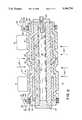
- FIG. 1is a plan view, partially in section, of one embodiment of a tubular, stepped, stacked, oxygen generator used in this invention, showing the cell configuration, end seal portions, power contacting connections, and source of air;
- FIG. 2shows another embodiment of the oxygen generator used in this invention, in plan view partially in section;
- FIG. 3is a top cross-sectional view of an oxygen generation system according to the present invention.
- FIG. 4is a front elevational cross-sectional view of an oxygen generation system according to the present invention.
- FIG. 5is a front, elevational view in partial cross-section according to one embodiment of the present invention.
- FIG. 4shows a front elevational cross-sectional view of the invention.
- An outer housing 110has an inner surface 112, an outer surface 114, a top surface 116, and a base surface 118.
- an inner housing 120has an inner surface 122, an outer surface 124, a top surface 126, and a base surface 128.
- both the outer housing 110 and the inner housing 120are cylindrical, taking the form of an annulus.
- the inner housing 120is mounted concentrically within the outer housing 110.
- a first passageway 150is formed between the inner surface 122 of the inner housing 120 and the outer surface 142 of the generator 10.
- a second air passageway 130is formed between the outer surface 124 of the inner housing 120 and the inner surface 112 of the outer housing 110.
- a cap 160is attached to the top surface 116 of the outer housing 110.
- the cap 160forms a mixing zone 170 above the first and second passageways 150, 130.
- the cap 160has a plurality of fins 162 mounted to its inner periphery. The operation of these fins 162 will be described below.
- infrared shields 180, 182are mounted above and below the first and second passageways 150, 130 and are effective to reflect infrared radiation emanatinq from the generator 10 back into the generation system.
- these shieldsare parabolic.
- the interior surface of the cap 160is coated with a reflective material and is curved to form reflective shield 182.
- the cap 160is also insulated to retain heat.
- a first and second blower 190, 192are utilized in the preferred embodiment of the invention and are schematically shown in FIG. 4. The purpose and operation of these blowers will be discussed below.
- Oxygen generated by the generation systemis removed from the device via discharge tube 200. Because the oxygen is generated at a pressure above atmospheric pressure, the oxygen flows out of discharge tube 200 without the need for a blower or pump.
- One of the primary objectives of the deviceis to provide a steady stream of air to the generator 10 in such quantities so as to insure a sufficient production of oxygen from the generator 10. Also, this air must be supplied with a minimum amount of noise generated or energy expended. Preferably, the air is preheated before it reaches the generator 10.
- the deviceutilizes several air passageways, with their associated inlets and outlets, to accomplish these objectives. For purposes of illustration, the outlets will be designated as follows.
- a first inlet 210 of the first passageway 150is located near the base surface 128 of the inner housing 120.
- a first outlet 212 of the first passageway 150is located near the top surface 126 of the inner housing 120.
- a second inlet 220 of the second passageway 130is located near the top surface 116 of the outer housing 110.
- a second outlet 222 of the second passageway 130is located near the base surface 118 of the outer housing 110.
- the lower portions of the second passageway 130are angled inwardly so as to reduce losses due to friction within the second passageway 130.
- an additional transition passageway 226is formed.
- the transition passageway 226begins with a third inlet 230 and terminates with a third outlet 232.
- the third inlet 230 of the transition passageway 226cooperates with the second outlet 222 of the second passageway 130 and the third outlet 232 of the transition passageway 226 cooperates with the first inlet 210 of the first passageway 150 so that air exiting the second passageway 130 enters the transition passageway 226.
- a fourth inlet 240is located in the cap 160.
- Air flow under operating conditionsis as follows. With continuing reference to FIGS. 3 and 4, the second blower 192 introduces ambient air into the fourth inlet 240 of the cap 160. The air is introduced tangentially to contribute to a circular, swirling condition in the mixing zone 170 inside the cap 160. Fins 162 contribute to this circular air flow. The direction of air flow is shown in FIG. 3.
- air in the first passageway 150is warmer than air in other places throughout the device. As such, air exiting the first outlet 212 tends to be warmer than air entering the mixing zone 170 at the fourth inlet 240.
- the cooler air entering the mixing zone 170 at the fourth inlet 240tends to drop downwardly through the second inlet 220 of the second passageway 130.
- the airtravels downwardly through the second passageway 130, out the second outlet 222, and into the transition passageway 226. After exiting the transition passageway 226, the air tends to be drawn into first inlet 210 of the first passageway 150. While in the first passageway 150, the air travels longitudinally along the outer surface 142 of the generator 10.
- This vortexis one of two non-mechanical mechanisms which help air circulate within the system.
- a secondis thermal convection currents. Pressure is created by cooler, dense air in the second passageway 130 accumulating near the first inlet 210 of the first passageway 150. This cooler air exiting the transition passageway 226 tends to accumulate at the first inlet 210 of the first passageway 150. This cooler air, being more dense than the warmer air, tends to fall downwardly within the second passageway 130 and displace warmer air near the first inlet 210. This displaced warmer air rises, bringing it into closer association with the generator 10. This closer association raises the temperature of the air even higher, causing it to become less dense and to rise even faster. The warmer air rises due to the principle of convection. By these mechanisms, air is circulated through the device with a minimum of electrical power expended and noise generated.
- the air flow generated by the second blower 192can be adjusted during start up to assist in heating up the device to operating temperatures.
- the second blower 192is effective to introduce ambient air into the fourth inlet 240 of the cap 160.
- the airis introduced tangentially and is directed by the fins 162 to the second inlet 220 of the second passageway 130.
- the air in the second passagewaytends to drop downwardly due to its relatively high density to the warmer air rising upwardly in the first passageway 150.
- air in the second passageway 130drops downwardly while air in the first passageway 150 travels upwardly.
- the positive pressure created by the second blower 192 within the cap 160overcomes the forces of convection and air travels downwardly in both the second passageway 130 and the first passageway 150. In this condition, the temperature of the generator 10 drops, since it is being bathed by cooler incoming air.
- the outer housing 110is supported by a support 244. Mounted within the support 244 is an infrared shield 180.
- the infrared shield 180is positioned beneath the inner housing 120 and the opening 246 in the outer housing 110. Because the generator 10 operates at high temperature, a significant amount of infrared radiation emanates from the opening 246 in the base of the outer housing 110 and from the inner surface 122 of the inner housing 120. Allowing this radiation to escape would be a waste of energy and could create uncomfortable conditions in the environment, for example, if the device was mounted near a hospital bed.
- the infrared shield 180is effective to reflect infrared radiation emanating from generator 10 back into opening 246. This process saves energy and makes the ambient environment more comfortable for the patient by keeping the heat within the device.
- the inner surface of the cap 160is curved and coated with a reflective material to act as an infrared shield 182 to reflect infrared radiation emanating from the top of the generator 10.
- the first blower 190also mounted within the support 244 is a first blower 190.
- the first blowermixes a large amount of ambient cool air with warmer air escaping from opening 246 in the outer housing 110. This mixing dramatically lowers the temperature of the air escaping from opening 246.
- discharge tube 200is fed back through the fourth outlet 240.
- the oxygen generated by generator 10 and discharged through discharge tube 200is warm compared to the incoming air through second blower 192 and fourth inlet 240.
- the cooler incoming airis warmed by the hot oxygen being discharged through discharge tube 200. This is effective in lowering the temperature of the oxygen for the patient's use as well as saving the energy present within the oxygen and transferring it to the incoming air.
- the interior of the inner and outer housing 120, 110is insulated with alumino silicate which is shown at 121, 111.
- the insulationhas a reflective backing which holds the fibers together, as well as contributing to the efficiency of the device by reflecting infrared radiation back into the passageways 130, 150, 230.
- the preferred insulation materialis manufactured by the Carborundum Company under the trade name Fiberfrax® HSA Systems.
- silver lead wiresfor electrical connections. Because the device operates at about 900° C., care must be taken to chose materials which will retain operational and dimensional stability at those temperatures. Silver melts at 961° C., and therefore can remain dimensionally stable at these operating temperatures. Another advantage is that silver will not oxidize. While gold and platinum will also work, silver is preferred for applications which operate at temperatures below its melting point because it is cheaper and is not subject to oxidation, as is platinum. Platinum, with a melting point of 1,769° C., is the preferred material at operating temperatures above the melting points of gold and silver.
- tubularis meant to include any axially elongated structural form having a closed cross-section.
- air electrodemeans that electrode which contacts ambient air on the outside of the generator and allows formation of oxygen ions from oxygen in the air.
- oxygen electrodemeans that electrode which allows formation of oxygen gas from oxygen ions and allows passage of the oxygen gas into the interior of the generator.
- dischargemeans at least 95% of the theoretical density.
- the generatoris driven by a DC power source. It operates at from 650° C. to 1,100° C. with preheated air which can be unpressurized.
- the generatoris able to extract pure oxygen at the electrolyte surface at a rate proportional to the electric current.
- a high temperature electrochemical device 10 useful as an oxygen generatorhaving a closed cross-section, preferred tubular form, and comprising a plurality of adjacent electrochemical cells, the active lengths of which are shown as first cell 12 and adjacent cell 12', arranged end to end.
- a single tubular oxygen generatoris used.
- a series of tubular oxygen generatorscan be placed within a single inner housing. In such cases, the currently preferred arrangement is a hexagonal array.
- the cellsare electrically connected in series through continuous, spaced-apart solid oxide electrolyte bands or segments 14, continuous, spaced-apart air electrode band 16, continuous, spaced-apart interconnection segments 18, and continuous, spaced-apart oxygen electrode bands 20.
- porous support 22which is preferably from 20% to 40% porous (80% to 60% of theoretical density), and which is generally used, as shown, supports oxygen electrodes 20 and the rest of the structure.
- Dense, solid electrolyte 14is disposed on top of part of the inner oxygen electrode 20 starting a predetermined length from a first end 20' of each oxygen electrode.
- Outer porous air electrode 16is disposed on top of part of the electrolyte 14 and in contact with air 23 which surrounds the generator body 10.
- the dense electrolyte 14overlaps the dense inter-connection 18 between cells 12 and 12' and overlaps the dense inter-connection 18 near the positive terminal 26, which latter connection forms a dense end portion for that device. This overlapping produces a gas impermeable barrier between the outside and the inside of the device.
- Air electrode 16 from cell 12is deposited on top of the electrolyte 14 from cell 12 continuing until contacting the inter-connection 18 between cells 12 and 12'. To prevent electrical shorting between cells, a gap region is maintained between the air electrode 16 of cell 12, and the electrolyte 14 of cell 12'.
- These coatings of materialscan be laid down by any suitable application masking techniques, such as electrochemical vapor deposition, sputtering, powder sintering, plasma arc spraying, and the like.
- Electrochemical vapor depositionis a preferred method of depositing electrolyte and inter-connection materials, and reference may be made to U.S. Pat. No. 4,609,562 (Isenberg, et al.) herein incorporated by reference for details on that process.
- the reactionsare:
- the tubular segment of inter-connection material between cellsprovides electrical continuity (allows a flow of electrons) from the outer air electrode from a first cell 12' to the inner oxygen electrode of a second cell 12, on the same device or tube, in a series arrangement.
- air 23is prevented from directly passing into the central chamber 25 by a continuous, dense, preferably 100% dense, barrier of electrolyte bands or segments 14 and inter-connect segments 18.
- the dense electrolyte bands or segmentsin part, overlap and seal to the dense inter-connection segments 18.
- This air impermeability of the generator bodyis essential to providing high purity O 2 , i.e. over approximately 95% pure, in the central chamber. While length 12 and 12' define the "active" lengths of the two cells shown in FIG. 1 and in FIG.
- electrode and electrolyte components shown extending out beyond the active lengthare considered the active part from that particular cell. While the incoming air 23 does not have to be over atmospheric pressure, a great advantage in terms of the oxygen supply system, it may preheated consistent with the overall system design previously described prior to contact with the air electrodes 16 of the generator.
- a variety of end closures or portions, preferably dense,can be used in the apparatus shown.
- the dense inter-connection portion 18', near the positive terminal, and the dense electrolyte portion 14', near the negative terminalare overlapped at the ends of the device and disposed transverse to the axial length of the device, as shown, to provide end closures.
- a high temperature resistant metal, central, axial rod, tube or the like 30, of, for example, Inconel (nickel-chromium alloy), having threads at each end,can be use in conjunction with metal end sheets 28 and 28', to secure the sheets and the dense inter-connection and electrolyte portions in a compressed relationship.
- one end of the rodwould be screwed into a mated thread, machined into the inner side of sheet 28', and the other end would be screwed down onto insulating rings 32 by an effective spring means (not shown), applying axial pressure to the end sheets, and assuring a gas tight fit against the flat metal terminals 24 and 26.
- the generator 10is preheatable by placing a voltage differential at the opposite ends of the axial rod 30.
- the rod 30 materialis chosen to develop the desired heat at the desired current levels.
- a suitable, high temperature resistant metal or ceramic tubular sleeve 34having a plurality of vents or holes 36 therethrough, suitably sealed to end sheet 28, can provide oxygen delivery through the end closures 18', as shown by the O 2 arrows.
- Inconel and aluminawould both be suitable as the sleeve 34. In some instances, it may be desirable to have oxygen delivery though both ends.
- an additional holecan be drilled through end closure 18', and air electrode 16, terminal 26 ceramic ring 32 and end sheet 28, and a tube inserted for oxygen delivery, similar to 38 in FIG. 2. This tube 38 can be made to cooperate with discharge tube 200 of FIGS. 3 and 4.
- the design of FIG. 1utilizes a substantial amount of metal hardware in contact with ceramic components.
- the cell structure and inter-connection between cellsare essentially the same as the device of FIG. 1, utilizing the same materials and substantially the same cell connection design.
- ceramic end portions or caps 40 and 42are used in place of the end overlapping inter-connection 18' and end overlapping electrolyte 14' design of FIG. 1.
- This userequires a sinter seal comprising very fine ceramic particles (not shown) between end portions or caps 40 and 42 and the ceramic support 22.
- the ceramic end portionsare preferably dense, to the degree of being gas impervious, and are preferably of the same material as the support tube.
- the ceramic support tube 22in both embodiments, will be a zirconia material, such as stablilized zirconia, most preferably calcia-stabilized zirconia, for example (ZrO 2 ) 0 .85 (CaO) 0 .15.
- This materialis pressed and highly densified form, is preferably also used as the ceramic end portions or caps 40 and 42 in FIG. 2.
- a seal(end portion or cap to support tube) is produced by squeezing in a preformulated paste of very fine particle size calcia stabilized zirconia into the gap region when the end portions or caps are inserted.
- the ceramic end seal assemblyis then dried and sintered in place, to complete fabrication.
- the narrow gap of the joint, the long, tortuous path, and the near-ambient pressure during operation of the devicewill all contribute to minimize leakage of any air into the central chamber 25 so that high purity O 2 can be provided.
- a minor amount of sintering aidsuch as FeO for example, can be used in the adhesive paste and can also be used in both the support tube and end caps.
- Other suitable ceramic materialscan also be used for the support tube, and the end caps which overlap the end of support tube 22.
- any useful high temperature adhesivecan also be used between those components to assure minimal air permeation into central chamber 25.
- the terminal connections on the device of FIG. 1are of simple round washer design, having an extending bus bar contact area secured by pressure tightening rod 30, where the terminals 24 and 26 are preferably silver (m.p. 961° C.), but can also be platinum (m.p. 1,769), or palladium and alloys of palladium and platinum with silver, if the device is to be operated close to its 1,100° C. maximum operating temperature.
- terminal attachmentsare of circular band design, and directly electrically contact the top surface of the inter-connection material at one end and the air electrode material at the other end of the device, and require cushioning layers.
- the negative terminal 24electrically contacts the air electrode 16, preferably through a fiber metal ring 44, preferably of silver-palladium fibers.
- a metallic split ring clampconstitutes the terminals 24 and 26, which are shown partly in section.
- the terminals 24 and 26are preferably silver-palladium alloy, but can also be solid nickel, preferably coated with silver-palladium alloy.
- Terminal 26 in the FIG. 2 designelectrically contact inter-connection material 18 and may require an additional fiber metal ring 46, preferably of silver-palladium. Also shown in FIG.
- Oxygen gas from the central chamber 25 shown in FIG. 2can be delivered through tube 38, which is preferably of a ceramic such as calcia-stabilized zirconia, or by any other appropriate means at one or both ends.
- porous support tube44 mm inside diameter, 50 mm outside diameter by 450 mm long; porous oxygen electrode: 15 mm long by 1 mm thick; dense interconnection: 0.05 mm to 2 mm thick; dense electrolyte: 11 mm long by 0.05 mm thick; and porous air electrode: 15 mm long by 0.1 mm thick.
- the unitwould be a single stack, having a multiplicity of series-connected cells each about 1.1 cm long having an area of approximately 18 cm 2 .
- the drawingsare not shown to scale.
- the oxygen electrode 20, preferably from 0.5 mm to 2 mm thick,is a 20% to 40% porous, sintered oxide material selected from doped and undoped oxides or mixtures of oxides in the pervoskite family, such as CaMnO 3 , LaNiO 3 , LaCoO 3 , and preferably LaMnO 3 , or other electronically conducting mixed oxides generally composed of rare earth oxides mixed with oxides of cobalt, nickel, copper, iron, chromium and manganese, and combinations of such oxides.
- Dopants when usedare preferably selected from calcium, strontium, and magnesium, with strontium dopant preferred.
- the most preferred oxygen electrodeis lanthanum manganite doped with strontium, for example La 0 .9 Sr 0 .1 MnO 3 .
- the air electrodeis preferably applied by dip slurry application and sintering.
- the dense inter-connection material, 18,can be selected from the group consisting of platinum-zirconia, palladium-zirconia, silver-palladium-zirconia, palladium, platinum, palladium-silver, doped lanthanum manganite, and doped lanthanum chromite.
- the preferred inter-connection materialis selected from the group consisting of doped lanthanum manganite, palladium, platinum, and palladium-silver.
- Dopants for the lanthanum manganite or lanthanum chromiteare selected from the group consisting of calcium, strontium, and magnesium, with strontium dopant preferred.
- the most preferred inter-connectionis doped lanthanum manganite.
- the inter-connection materialis gas impervious and near 100% dense. It can be applied by well known vapor deposition techniques, and is usually from 0.05 mm to 2 mm thick. Densification can be achieved by a variety of techniques besides vapor deposition, including vapor sputtering, plasma spray, flame spray, and the like. In some cases, the inter-connection, oxygen electrode, and air electrode can be the same material differing only in density and application technique, with the inter-connection being the high density component.
- the zirconiacan be stabilized, that is, doped with a number of elements.
- Rare earth element stabilized zirconia, specifically yttria-stabilized zirconiais preferred, as it allows excellent oxygen ion mobility.
- a most preferred compositionis (ZrO 2 ) 0 .92 (Y 2 O 3 ) 0 .08.
- Other mixed oxidescan be used.
- the materialmust be effective to transfer ionic oxygen. It can be applied by chemical vapor deposition, plasma spray, flame spray, or sintering techniques.
- the porous air electrode, 16, preferably from 0.05 mm to 2 mm thick,is a 20% to 60% porous material selected from metal-ceramic materials selected from the group consisting of platinum-zirconia, palladium-zirconia, and silver-palladium-zirconia, or a porous, sintered oxide selected from the group consisting of doped lanthanum manganite and doped lanthanum chromite where the preferred dopants are calcium, strontium, and magnesium, with strontium dopant preferred.
- Palladium-zirconiais the most preferred air electrode material.
- the air electrodemust be effective to allow reduction of O 2 in the air to oxygen ions.
- the deviceoperates at 900° C. at a current density of 2 amperes/cm 2 , with ambient, unpressurized air delivery to the device.
- the preferred embodiment oxygen generator 10was manufactured by Westinghouse Electric Corporation.
- the power dissipated as heat in the oxygen concentration systemmaintains the operating temperature.
- the power required to maintain 900° C.is about 500 watts.
- An oxygen concentration system sufficient to deliver this flow rate at these conditionswould have 22 cells operating at 631 millivolts and 36 amperes/cell.
- the heat generated by such a systemis 500 watts and the operating temperature will be maintained by the electrochemical production of oxygen.
- One advantage to this oxygen generation systemis its ability to generate oxygen at flow rates which are proportional to the electrical current supplied to the generator 10. For example, if a flow rate of 1 liter/minute is desired, the oxygen generation system requires only 12 amperes be supplied to the generator 10. The cell voltage is calculated by Ohms Law and will be 210 millivolts. The power dissipated in this case is only 55 watts. This is not enough heat to maintain the operating temperature and the generator 10 cannot operate correctly. The difference between the oxygen generation heat and the temperature maintenance heat must be made up by an additional heater.
- One advantage of the preferred embodiment of the inventionis the use of the lnconel closure rod 30 as a heat source. Electric current can be imposed on the rod 30 such that the rod dissipates the amount of heat required to maintain the operating temperature. The higher the oxygen flow rate, the lower the amount of heat required to be generated by the rod.
- Another advantage of using the rod 30 to generate heatis the uniformity of the heating. High heating rates can be obtained upon the initial start up with the rod 30 centered inside the generator 10. Because the system is symmetrical about an axis, stresses developed due to uneven heating are minimized.
- rod 30 and the cylindrical layout of the oxygen concentration systemis the efficient use of heat. For example, if the heater were to be located outside the generator 10, then a portion of the heat would be directed toward the generator 10 and the remainder would be dissipated away from the generator. Because the rod 30 passes through the center of the generator 10 substantially all of the heat generated by the rod 30 heats the generator 10.
- a plurality of generators 10is a preferred configuration.
- a preferred configuration of the generatorsis in the form of a hexagonal array.
- Nnumber of generators along a radius of the array
- the arraywould feature a single generator 10 in the center, surrounded by six generators 10, which in turn are surrounded by twelve generators 10.
- N4 and thirty-seven generators 10 are in the array.
- the hexagonal configuration of the arrayis advantageous for minimizing the volume necessary to accommodate a certain number of generators 10.
- the hexagonal shapepermits a large number of generators 10 to be put into a small volume.
- the following chartshows how the hexagonal arrangement of the generators 10 allows for greatly increased oxygen production without a proportionate increase in volume required.
- the hexagonal configurationalso aids in retaining heat within the inner housing 120.
- the configurationprovides for uniform heating of the generators 10 within the inner housing 120 via radiation.
Landscapes
- Chemical & Material Sciences (AREA)
- Organic Chemistry (AREA)
- Inorganic Chemistry (AREA)
- Chemical Kinetics & Catalysis (AREA)
- General Chemical & Material Sciences (AREA)
- Analytical Chemistry (AREA)
- Electrochemistry (AREA)
- Engineering & Computer Science (AREA)
- Oil, Petroleum & Natural Gas (AREA)
- Oxygen, Ozone, And Oxides In General (AREA)
Abstract
Description
1, 7, 19, 37, 61, 91, 127, 169, 217, 271, . . .
__________________________________________________________________________Generator Diameter = 2 inches No. Cells = 53 Generator Voltage = 37 volts Cell Length = 0.7 inches Generator Current = 36 amps Cell Area = 2.8 sq. in. Generator Length = 39 inches System Height = 60 inches __________________________________________________________________________No. Oxygen System System System Power Power of Delivery Diameter Volume Weight Required Required Generators (1 pm@RTP) (inches) (cu. ft.) (lbs) (kW) (hp) __________________________________________________________________________ 1 7 8 2 41 1 2 7 50 11 3 56 9 12 19 137 16 7 139 25 34 37 268 21 12 263 49 66 61 442 26 18 628 81 109 91 659 31 26 628 121 163 127 921 36 35 870 170 227 __________________________________________________________________________
Claims (56)
1,7,19,37,61,91,127,169 . . . 1+Σ6(n-1)
Priority Applications (4)
| Application Number | Priority Date | Filing Date | Title |
|---|---|---|---|
| US07/636,487US5186793A (en) | 1990-12-31 | 1990-12-31 | Oxygen concentrator utilizing electrochemical cell |
| US07/689,145US5169506A (en) | 1990-12-31 | 1991-04-22 | Oxygen concentration system utilizing pressurized air |
| JP4103022AJPH06170151A (en) | 1990-12-31 | 1992-04-22 | Oxygen concentrating device using electrochemical cell |
| US08/143,297US5397443A (en) | 1990-12-31 | 1993-10-26 | Method of assembling tubular electrochemical oxygen generators |
Applications Claiming Priority (1)
| Application Number | Priority Date | Filing Date | Title |
|---|---|---|---|
| US07/636,487US5186793A (en) | 1990-12-31 | 1990-12-31 | Oxygen concentrator utilizing electrochemical cell |
Related Child Applications (2)
| Application Number | Title | Priority Date | Filing Date |
|---|---|---|---|
| US07/689,145Continuation-In-PartUS5169506A (en) | 1990-12-31 | 1991-04-22 | Oxygen concentration system utilizing pressurized air |
| US92331792AContinuation | 1990-12-31 | 1992-07-31 |
Publications (1)
| Publication Number | Publication Date |
|---|---|
| US5186793Atrue US5186793A (en) | 1993-02-16 |
Family
ID=24552125
Family Applications (2)
| Application Number | Title | Priority Date | Filing Date |
|---|---|---|---|
| US07/636,487Expired - LifetimeUS5186793A (en) | 1990-12-31 | 1990-12-31 | Oxygen concentrator utilizing electrochemical cell |
| US08/143,297Expired - LifetimeUS5397443A (en) | 1990-12-31 | 1993-10-26 | Method of assembling tubular electrochemical oxygen generators |
Family Applications After (1)
| Application Number | Title | Priority Date | Filing Date |
|---|---|---|---|
| US08/143,297Expired - LifetimeUS5397443A (en) | 1990-12-31 | 1993-10-26 | Method of assembling tubular electrochemical oxygen generators |
Country Status (1)
| Country | Link |
|---|---|
| US (2) | US5186793A (en) |
Cited By (26)
| Publication number | Priority date | Publication date | Assignee | Title |
|---|---|---|---|---|
| EP0761284A1 (en)* | 1995-08-24 | 1997-03-12 | Litton Systems, Inc. | Modular ceramic oxygen generator |
| EP0875281A1 (en)* | 1997-04-29 | 1998-11-04 | Praxair Technology, Inc. | Integrated solid electrolyte ionic conductor separator-cooler |
| US6033457A (en)* | 1998-03-23 | 2000-03-07 | Oxynet, Inc. | Oxygen generator system and method of operating the same |
| RU2151219C1 (en)* | 1999-06-21 | 2000-06-20 | Открытое акционерное общество "Уральский научно-исследовательский технологический институт" | Oxygen generator |
| RU2154017C1 (en)* | 1999-08-30 | 2000-08-10 | Открытое акционерное общество "Уральский научно-исследовательский технологический институт" | High-temperature electrolyzer |
| US6129165A (en) | 1996-07-03 | 2000-10-10 | Pride Mobility Products, Corporation | Curb-climbing power wheelchair |
| EP1057517A1 (en)* | 1999-06-01 | 2000-12-06 | Litton Systems, Inc. | Electrochemical oxygen generating system |
| US6176335B1 (en) | 1996-07-03 | 2001-01-23 | Pride Mobility Products, Corporation | Power wheelchair |
| US6186252B1 (en) | 1996-07-03 | 2001-02-13 | Pride Mobility Products, Corporation | Foldable midwheel drive power chair |
| US6290757B1 (en) | 1999-03-26 | 2001-09-18 | Ceramphysics, Inc. | Nitrogen purification device |
| US6368491B1 (en) | 2000-11-08 | 2002-04-09 | Northrop Grumman Corporation | Method of controlling a modular ceramic oxygen generating system |
| US6511526B2 (en) | 2001-01-12 | 2003-01-28 | Vbox, Incorporated | Pressure swing adsorption gas separation method and apparatus |
| US6592731B1 (en) | 1999-09-23 | 2003-07-15 | Ceramphysics, Inc. | Amperometric oxygen sensor |
| US6685235B1 (en) | 2000-05-19 | 2004-02-03 | Carleton Life Support Systems, Inc. | System and method for attaching tubing |
| US6824661B2 (en) | 1999-09-23 | 2004-11-30 | Ceramphysics, Inc. | Combined oxygen and NOx sensor |
| WO2009014785A3 (en)* | 2007-05-03 | 2009-03-12 | Battelle Memorial Institute | Oxygen generation for battlefield applications |
| US20090159434A1 (en)* | 2006-04-11 | 2009-06-25 | Guillaume Girault | System and process for collecting effluents from an electrolytic cell |
| US20110197890A1 (en)* | 2005-02-09 | 2011-08-18 | Vbox, Incorporated | Ambulatory oxygen concentrator |
| US8394178B2 (en) | 2009-07-22 | 2013-03-12 | Vbox, Incorporated | Apparatus for separating oxygen from ambient air |
| US9797054B2 (en) | 2014-07-09 | 2017-10-24 | Carleton Life Support Systems Inc. | Pressure driven ceramic oxygen generation system with integrated manifold and tubes |
| US9956371B2 (en) | 2015-03-24 | 2018-05-01 | Ventec Life Systems, Inc. | Ventilator with integrated cough-assist |
| US10773049B2 (en) | 2016-06-21 | 2020-09-15 | Ventec Life Systems, Inc. | Cough-assist systems with humidifier bypass |
| US11191915B2 (en) | 2018-05-13 | 2021-12-07 | Ventec Life Systems, Inc. | Portable medical ventilator system using portable oxygen concentrators |
| US11247015B2 (en) | 2015-03-24 | 2022-02-15 | Ventec Life Systems, Inc. | Ventilator with integrated oxygen production |
| US20230324965A1 (en)* | 2022-04-06 | 2023-10-12 | Microsoft Technology Licensing, Llc | Device Cooling |
| US12440634B2 (en) | 2021-12-21 | 2025-10-14 | Ventec Life Systems, Inc. | Ventilator systems with integrated oxygen delivery, and associated devices and methods |
Families Citing this family (21)
| Publication number | Priority date | Publication date | Assignee | Title |
|---|---|---|---|---|
| US5695624A (en)* | 1995-01-30 | 1997-12-09 | The Regents Of The Univeristy Of California | Solid state oxygen sensor |
| US5543025A (en)* | 1995-01-30 | 1996-08-06 | The Regents Of The University Of California, Office Of Technology Transfer | Solid state oxygen sensor |
| US7713190B2 (en)* | 1998-02-24 | 2010-05-11 | Hansen Medical, Inc. | Flexible instrument |
| US6626899B2 (en) | 1999-06-25 | 2003-09-30 | Nidus Medical, Llc | Apparatus and methods for treating tissue |
| US7766894B2 (en)* | 2001-02-15 | 2010-08-03 | Hansen Medical, Inc. | Coaxial catheter system |
| US7976539B2 (en)* | 2004-03-05 | 2011-07-12 | Hansen Medical, Inc. | System and method for denaturing and fixing collagenous tissue |
| WO2005087128A1 (en) | 2004-03-05 | 2005-09-22 | Hansen Medical, Inc. | Robotic catheter system |
| US7396442B2 (en)* | 2005-02-08 | 2008-07-08 | Carleton Life Support Systems, Inc. | Electrochemical oxygen generator module assembly |
| JP2009500086A (en) | 2005-07-01 | 2009-01-08 | ハンセン メディカル,インク. | Robotic guide catheter system |
| US8658007B2 (en)* | 2005-07-15 | 2014-02-25 | The Trustees Of Boston University | Oxygen-producing inert anodes for SOM process |
| US9254123B2 (en) | 2009-04-29 | 2016-02-09 | Hansen Medical, Inc. | Flexible and steerable elongate instruments with shape control and support elements |
| US20120191079A1 (en) | 2011-01-20 | 2012-07-26 | Hansen Medical, Inc. | System and method for endoluminal and translumenal therapy |
| US20130030363A1 (en) | 2011-07-29 | 2013-01-31 | Hansen Medical, Inc. | Systems and methods utilizing shape sensing fibers |
| US20140148673A1 (en) | 2012-11-28 | 2014-05-29 | Hansen Medical, Inc. | Method of anchoring pullwire directly articulatable region in catheter |
| US20140277334A1 (en) | 2013-03-14 | 2014-09-18 | Hansen Medical, Inc. | Active drives for robotic catheter manipulators |
| US9326822B2 (en) | 2013-03-14 | 2016-05-03 | Hansen Medical, Inc. | Active drives for robotic catheter manipulators |
| US9408669B2 (en) | 2013-03-15 | 2016-08-09 | Hansen Medical, Inc. | Active drive mechanism with finite range of motion |
| US20140276936A1 (en) | 2013-03-15 | 2014-09-18 | Hansen Medical, Inc. | Active drive mechanism for simultaneous rotation and translation |
| US10046140B2 (en) | 2014-04-21 | 2018-08-14 | Hansen Medical, Inc. | Devices, systems, and methods for controlling active drive systems |
| US10463439B2 (en) | 2016-08-26 | 2019-11-05 | Auris Health, Inc. | Steerable catheter with shaft load distributions |
| US11241559B2 (en) | 2016-08-29 | 2022-02-08 | Auris Health, Inc. | Active drive for guidewire manipulation |
Citations (30)
| Publication number | Priority date | Publication date | Assignee | Title |
|---|---|---|---|---|
| US1120436A (en)* | 1913-09-30 | 1914-12-08 | Ludwig Bergfeld | Separation of oxygen from the air. |
| US3400054A (en)* | 1966-03-15 | 1968-09-03 | Westinghouse Electric Corp | Electrochemical method for separating o2 from a gas; generating electricity; measuring o2 partial pressure; and fuel cell |
| US3410783A (en)* | 1966-02-02 | 1968-11-12 | Allis Chalmers Mfg Co | Electrochemical cell for separation of gaseous mixtures |
| US3888749A (en)* | 1972-08-31 | 1975-06-10 | Sun Research Development | Electrolytic separation of oxygen from air |
| USRE28792E (en)* | 1966-03-15 | 1976-04-27 | Westinghouse Electric Corporation | Electrochemical method for separating O2 from a gas; generating electricity; measuring O2 partial pressure; and fuel cell |
| US4061554A (en)* | 1975-04-24 | 1977-12-06 | Societe Generale De Constructions Electriques Et Mecaniques "Alsthom Et Cie" | Electrochemical method for producing oxygen |
| US4089938A (en)* | 1977-07-15 | 1978-05-16 | Hudson Engineering Corporation | Process for recovering oxygen from air |
| US4132766A (en)* | 1977-05-24 | 1979-01-02 | Erickson Donald C | Separation of oxygen from gaseous mixtures with molten alkali metal salts |
| US4287170A (en)* | 1980-03-06 | 1981-09-01 | Erickson Donald C | Nitrogen and oxygen via chemical air separation |
| US4300987A (en)* | 1978-04-14 | 1981-11-17 | Tseung Alfred C C | Gas extraction |
| US4340578A (en)* | 1977-05-24 | 1982-07-20 | Erickson Donald C | Oxygen production by molten alkali metal salts |
| US4341847A (en)* | 1980-10-14 | 1982-07-27 | Institute Of Gas Technology | Electrochemical zinc-oxygen cell |
| US4377460A (en)* | 1981-10-19 | 1983-03-22 | Westinghouse Electric Corp. | Solid electrolyte gas sensing apparatus |
| US4391690A (en)* | 1980-08-26 | 1983-07-05 | Westinghouse Electric Corp. | Apparatus for monitoring SO2 concentrations |
| US4395468A (en)* | 1980-12-22 | 1983-07-26 | Westinghouse Electric Corp. | Fuel cell generator |
| US4408951A (en)* | 1980-12-10 | 1983-10-11 | Tasuku Ishii | Fluid driven engine |
| US4431715A (en)* | 1982-03-24 | 1984-02-14 | Westinghouse Electric Corp. | Electrical contact structures for solid oxide electrolyte fuel cell |
| US4475994A (en)* | 1983-12-27 | 1984-10-09 | Maxdem Incorporated | Method and apparatus for separating oxygen from a gaseous mixture |
| US4490444A (en)* | 1980-12-22 | 1984-12-25 | Westinghouse Electric Corp. | High temperature solid electrolyte fuel cell configurations and interconnections |
| US4515874A (en)* | 1981-05-02 | 1985-05-07 | Brown, Boveri & Cie Ag | Electrochemical storage cell |
| US4526775A (en)* | 1984-02-23 | 1985-07-02 | Air Products And Chemicals, Inc. | Oxygen production by molten alkali metal salts using multiple absorption-desorption cycles |
| US4529577A (en)* | 1984-07-11 | 1985-07-16 | Air Products And Chemicals, Inc. | Oxygen/nitrogen production with molten alkali salts |
| US4565685A (en)* | 1984-09-14 | 1986-01-21 | Air Products And Chemicals, Inc. | Air separation with temperature and pressure swing |
| US4664987A (en)* | 1984-11-15 | 1987-05-12 | Westinghouse Electric Corp. | Fuel cell arrangement |
| US4738760A (en)* | 1987-09-01 | 1988-04-19 | Institute Of Gas Technology | Electrochemical separation of oxygen |
| US4808491A (en)* | 1988-02-16 | 1989-02-28 | Westinghouse Electric Corp. | Corner heating in rectangular solid oxide electrochemical cell generators |
| US4812329A (en)* | 1986-05-28 | 1989-03-14 | Westinghouse Electric Corp. | Method of making sulfur tolerant composite cermet electrodes for solid oxide electrochemical cells |
| US4876163A (en)* | 1987-12-18 | 1989-10-24 | Westinghouse Electric Corp. | Generator configuration for solid oxide fuel cells |
| US4888254A (en)* | 1987-04-06 | 1989-12-19 | Westinghouse Electric Corp. | Low circumferential voltage gradient self supporting electrode for solid oxide fuel cells |
| US4908113A (en)* | 1987-09-01 | 1990-03-13 | Institute Of Gas Technology | Apparatus for the electrochemical separation of oxygen |
Family Cites Families (1)
| Publication number | Priority date | Publication date | Assignee | Title |
|---|---|---|---|---|
| US5045169A (en)* | 1990-02-05 | 1991-09-03 | Westinghouse Electric Corp. | Solid oxide electrolyte electrochemical oxygen generator |
- 1990
- 1990-12-31USUS07/636,487patent/US5186793A/ennot_activeExpired - Lifetime
- 1993
- 1993-10-26USUS08/143,297patent/US5397443A/ennot_activeExpired - Lifetime
Patent Citations (30)
| Publication number | Priority date | Publication date | Assignee | Title |
|---|---|---|---|---|
| US1120436A (en)* | 1913-09-30 | 1914-12-08 | Ludwig Bergfeld | Separation of oxygen from the air. |
| US3410783A (en)* | 1966-02-02 | 1968-11-12 | Allis Chalmers Mfg Co | Electrochemical cell for separation of gaseous mixtures |
| US3400054A (en)* | 1966-03-15 | 1968-09-03 | Westinghouse Electric Corp | Electrochemical method for separating o2 from a gas; generating electricity; measuring o2 partial pressure; and fuel cell |
| USRE28792E (en)* | 1966-03-15 | 1976-04-27 | Westinghouse Electric Corporation | Electrochemical method for separating O2 from a gas; generating electricity; measuring O2 partial pressure; and fuel cell |
| US3888749A (en)* | 1972-08-31 | 1975-06-10 | Sun Research Development | Electrolytic separation of oxygen from air |
| US4061554A (en)* | 1975-04-24 | 1977-12-06 | Societe Generale De Constructions Electriques Et Mecaniques "Alsthom Et Cie" | Electrochemical method for producing oxygen |
| US4340578A (en)* | 1977-05-24 | 1982-07-20 | Erickson Donald C | Oxygen production by molten alkali metal salts |
| US4132766A (en)* | 1977-05-24 | 1979-01-02 | Erickson Donald C | Separation of oxygen from gaseous mixtures with molten alkali metal salts |
| US4089938A (en)* | 1977-07-15 | 1978-05-16 | Hudson Engineering Corporation | Process for recovering oxygen from air |
| US4300987A (en)* | 1978-04-14 | 1981-11-17 | Tseung Alfred C C | Gas extraction |
| US4287170A (en)* | 1980-03-06 | 1981-09-01 | Erickson Donald C | Nitrogen and oxygen via chemical air separation |
| US4391690A (en)* | 1980-08-26 | 1983-07-05 | Westinghouse Electric Corp. | Apparatus for monitoring SO2 concentrations |
| US4341847A (en)* | 1980-10-14 | 1982-07-27 | Institute Of Gas Technology | Electrochemical zinc-oxygen cell |
| US4408951A (en)* | 1980-12-10 | 1983-10-11 | Tasuku Ishii | Fluid driven engine |
| US4395468A (en)* | 1980-12-22 | 1983-07-26 | Westinghouse Electric Corp. | Fuel cell generator |
| US4490444A (en)* | 1980-12-22 | 1984-12-25 | Westinghouse Electric Corp. | High temperature solid electrolyte fuel cell configurations and interconnections |
| US4515874A (en)* | 1981-05-02 | 1985-05-07 | Brown, Boveri & Cie Ag | Electrochemical storage cell |
| US4377460A (en)* | 1981-10-19 | 1983-03-22 | Westinghouse Electric Corp. | Solid electrolyte gas sensing apparatus |
| US4431715A (en)* | 1982-03-24 | 1984-02-14 | Westinghouse Electric Corp. | Electrical contact structures for solid oxide electrolyte fuel cell |
| US4475994A (en)* | 1983-12-27 | 1984-10-09 | Maxdem Incorporated | Method and apparatus for separating oxygen from a gaseous mixture |
| US4526775A (en)* | 1984-02-23 | 1985-07-02 | Air Products And Chemicals, Inc. | Oxygen production by molten alkali metal salts using multiple absorption-desorption cycles |
| US4529577A (en)* | 1984-07-11 | 1985-07-16 | Air Products And Chemicals, Inc. | Oxygen/nitrogen production with molten alkali salts |
| US4565685A (en)* | 1984-09-14 | 1986-01-21 | Air Products And Chemicals, Inc. | Air separation with temperature and pressure swing |
| US4664987A (en)* | 1984-11-15 | 1987-05-12 | Westinghouse Electric Corp. | Fuel cell arrangement |
| US4812329A (en)* | 1986-05-28 | 1989-03-14 | Westinghouse Electric Corp. | Method of making sulfur tolerant composite cermet electrodes for solid oxide electrochemical cells |
| US4888254A (en)* | 1987-04-06 | 1989-12-19 | Westinghouse Electric Corp. | Low circumferential voltage gradient self supporting electrode for solid oxide fuel cells |
| US4738760A (en)* | 1987-09-01 | 1988-04-19 | Institute Of Gas Technology | Electrochemical separation of oxygen |
| US4908113A (en)* | 1987-09-01 | 1990-03-13 | Institute Of Gas Technology | Apparatus for the electrochemical separation of oxygen |
| US4876163A (en)* | 1987-12-18 | 1989-10-24 | Westinghouse Electric Corp. | Generator configuration for solid oxide fuel cells |
| US4808491A (en)* | 1988-02-16 | 1989-02-28 | Westinghouse Electric Corp. | Corner heating in rectangular solid oxide electrochemical cell generators |
Cited By (51)
| Publication number | Priority date | Publication date | Assignee | Title |
|---|---|---|---|---|
| EP0761284A1 (en)* | 1995-08-24 | 1997-03-12 | Litton Systems, Inc. | Modular ceramic oxygen generator |
| US6176335B1 (en) | 1996-07-03 | 2001-01-23 | Pride Mobility Products, Corporation | Power wheelchair |
| US6129165A (en) | 1996-07-03 | 2000-10-10 | Pride Mobility Products, Corporation | Curb-climbing power wheelchair |
| US6186252B1 (en) | 1996-07-03 | 2001-02-13 | Pride Mobility Products, Corporation | Foldable midwheel drive power chair |
| EP0875281A1 (en)* | 1997-04-29 | 1998-11-04 | Praxair Technology, Inc. | Integrated solid electrolyte ionic conductor separator-cooler |
| US6033457A (en)* | 1998-03-23 | 2000-03-07 | Oxynet, Inc. | Oxygen generator system and method of operating the same |
| US6290757B1 (en) | 1999-03-26 | 2001-09-18 | Ceramphysics, Inc. | Nitrogen purification device |
| EP1057517A1 (en)* | 1999-06-01 | 2000-12-06 | Litton Systems, Inc. | Electrochemical oxygen generating system |
| US6352624B1 (en) | 1999-06-01 | 2002-03-05 | Northrop Grumman Corporation | Electrochemical oxygen generating system |
| RU2151219C1 (en)* | 1999-06-21 | 2000-06-20 | Открытое акционерное общество "Уральский научно-исследовательский технологический институт" | Oxygen generator |
| RU2154017C1 (en)* | 1999-08-30 | 2000-08-10 | Открытое акционерное общество "Уральский научно-исследовательский технологический институт" | High-temperature electrolyzer |
| US6592731B1 (en) | 1999-09-23 | 2003-07-15 | Ceramphysics, Inc. | Amperometric oxygen sensor |
| US6824661B2 (en) | 1999-09-23 | 2004-11-30 | Ceramphysics, Inc. | Combined oxygen and NOx sensor |
| US6685235B1 (en) | 2000-05-19 | 2004-02-03 | Carleton Life Support Systems, Inc. | System and method for attaching tubing |
| US6368491B1 (en) | 2000-11-08 | 2002-04-09 | Northrop Grumman Corporation | Method of controlling a modular ceramic oxygen generating system |
| US6641644B2 (en) | 2001-01-12 | 2003-11-04 | Vbox, Incorporated | Pressure swing adsorption gas separation method and apparatus |
| US6511526B2 (en) | 2001-01-12 | 2003-01-28 | Vbox, Incorporated | Pressure swing adsorption gas separation method and apparatus |
| US20110197890A1 (en)* | 2005-02-09 | 2011-08-18 | Vbox, Incorporated | Ambulatory oxygen concentrator |
| US11389614B2 (en) | 2005-02-09 | 2022-07-19 | Vbox, Incorporated | Removable cartridge for oxygen concentrator |
| US10702669B2 (en) | 2005-02-09 | 2020-07-07 | Vbox, Incorporated | Removable cartridge for oxygen concentrator |
| US10357628B2 (en) | 2005-02-09 | 2019-07-23 | 3B Medical Manufacturing Llc | Removable cartridge for oxygen concentrator |
| US20090159434A1 (en)* | 2006-04-11 | 2009-06-25 | Guillaume Girault | System and process for collecting effluents from an electrolytic cell |
| WO2009014785A3 (en)* | 2007-05-03 | 2009-03-12 | Battelle Memorial Institute | Oxygen generation for battlefield applications |
| US20100180889A1 (en)* | 2007-05-03 | 2010-07-22 | Battelle Memorial Institute | Oxygen generation |
| US10335570B2 (en) | 2009-07-22 | 2019-07-02 | 3B Medical Inc. | Method of separating and distributing oxygen |
| US8394178B2 (en) | 2009-07-22 | 2013-03-12 | Vbox, Incorporated | Apparatus for separating oxygen from ambient air |
| US8597408B2 (en) | 2009-07-22 | 2013-12-03 | Vbox, Incorporated | Apparatus for separating oxygen from ambient air |
| US8695600B2 (en) | 2009-07-22 | 2014-04-15 | Vbox, Incorporated | Method of separating and distributing oxygen |
| US9797054B2 (en) | 2014-07-09 | 2017-10-24 | Carleton Life Support Systems Inc. | Pressure driven ceramic oxygen generation system with integrated manifold and tubes |
| US11247015B2 (en) | 2015-03-24 | 2022-02-15 | Ventec Life Systems, Inc. | Ventilator with integrated oxygen production |
| US11291791B2 (en) | 2015-03-24 | 2022-04-05 | Ventee Life Systems, Inc. | Ventilator with integrated cough-assist |
| US10105509B2 (en) | 2015-03-24 | 2018-10-23 | Ventec Life Systems, Inc. | Active exhalation valve |
| US10518059B2 (en) | 2015-03-24 | 2019-12-31 | Ventec Life Systems, Inc. | Passive leak valve |
| US10576237B2 (en) | 2015-03-24 | 2020-03-03 | Ventec Life Systems, Inc. | Active exhalation valve |
| US10046134B2 (en) | 2015-03-24 | 2018-08-14 | Ventec Life Systems, Inc. | Pressure swing adsorption oxygen generator |
| US10758699B2 (en) | 2015-03-24 | 2020-09-01 | Ventec Life Systems, Inc. | Secretion trap |
| US11992619B2 (en) | 2015-03-24 | 2024-05-28 | Ventec Life Systems, Inc. | Ventilator with integrated cough-assist |
| US11185655B2 (en) | 2015-03-24 | 2021-11-30 | Ventec Life Systems, Inc. | Passive leak valve |
| US11344692B2 (en) | 2015-03-24 | 2022-05-31 | Ventec Life Systems, Inc. | Respiratory therapy systems and methods |
| US10245406B2 (en) | 2015-03-24 | 2019-04-02 | Ventec Life Systems, Inc. | Ventilator with integrated oxygen production |
| US10315002B2 (en) | 2015-03-24 | 2019-06-11 | Ventec Life Systems, Inc. | Ventilator with integrated oxygen production |
| US9956371B2 (en) | 2015-03-24 | 2018-05-01 | Ventec Life Systems, Inc. | Ventilator with integrated cough-assist |
| US11679229B2 (en) | 2016-06-21 | 2023-06-20 | Ventec Life Systems, Inc. | Cough-assist systems with humidifier bypass |
| US10773049B2 (en) | 2016-06-21 | 2020-09-15 | Ventec Life Systems, Inc. | Cough-assist systems with humidifier bypass |
| US12246135B2 (en) | 2016-06-21 | 2025-03-11 | Ventec Life Systems, Inc. | Cough-assist systems with humidifier bypass |
| US11191915B2 (en) | 2018-05-13 | 2021-12-07 | Ventec Life Systems, Inc. | Portable medical ventilator system using portable oxygen concentrators |
| US12370333B2 (en) | 2018-05-13 | 2025-07-29 | Ventec Life Systems, Inc. | Portable medical ventilator system using portable oxygen concentrators |
| US12434026B2 (en) | 2018-05-13 | 2025-10-07 | Ventec Life Systems, Inc. | Portable medical ventilator system using portable oxygen concentrators |
| US12440634B2 (en) | 2021-12-21 | 2025-10-14 | Ventec Life Systems, Inc. | Ventilator systems with integrated oxygen delivery, and associated devices and methods |
| US20230324965A1 (en)* | 2022-04-06 | 2023-10-12 | Microsoft Technology Licensing, Llc | Device Cooling |
| US11829214B2 (en)* | 2022-04-06 | 2023-11-28 | Microsoft Technology Licensing, Llc | Device cooling |
Also Published As
| Publication number | Publication date |
|---|---|
| US5397443A (en) | 1995-03-14 |
Similar Documents
| Publication | Publication Date | Title |
|---|---|---|
| US5186793A (en) | Oxygen concentrator utilizing electrochemical cell | |
| EP0510877B1 (en) | Oxygen concentration system utilizing pressurized air | |
| EP0443259B1 (en) | Solid oxide electrochemical oxygen generator | |
| JP5153973B2 (en) | Electrochemical oxygen generation system | |
| US5827620A (en) | Solid oxide fuel cell structures | |
| US8070922B2 (en) | Monolithic supported oxygen generator | |
| US5409371A (en) | Oxygen welding and incorporating a novel gas separation system | |
| US6737182B2 (en) | Heated interconnect | |
| EP0500708A4 (en) | Solid state oxygen compressor | |
| EP1042536B1 (en) | Ceramic composite electrolytic device and method for manufacture thereof | |
| WO2011019796A1 (en) | Advanced solid state electrolytic device | |
| EP0565790B1 (en) | Oxygen concentrator utilizing electrochemical cell | |
| JPH06170151A (en) | Oxygen concentrating device using electrochemical cell | |
| GB2305169A (en) | Solid oxide fuel cells | |
| CA2288048A1 (en) | Improvements in and relating to gas generators | |
| JPH01267964A (en) | Fuel battery with solid electrolyte | |
| JP2007117893A (en) | Electrochemical cell |
Legal Events
| Date | Code | Title | Description |
|---|---|---|---|
| AS | Assignment | Owner name:INVACARE CORPORATION, 899 CLEVELAND STREET ELYRIA, Free format text:ASSIGNMENT OF ASSIGNORS INTEREST.;ASSIGNOR:MICHAELS, GREGORY A.;REEL/FRAME:005569/0108 Effective date:19901231 | |
| STCF | Information on status: patent grant | Free format text:PATENTED CASE | |
| FPAY | Fee payment | Year of fee payment:4 | |
| FPAY | Fee payment | Year of fee payment:8 | |
| FPAY | Fee payment | Year of fee payment:12 | |
| AS | Assignment | Owner name:NATIONAL CITY BANK, AS MULTICURRENCY COLLATERAL AG Free format text:NOTICE OF GRANT OF SECURITY INTEREST;ASSIGNOR:INVACARE CORPORATION;REEL/FRAME:019009/0134 Effective date:20070212 | |
| AS | Assignment | Owner name:PNC BANK, NATIONAL ASSOCIATION, PENNSYLVANIA Free format text:SECURITY AGREEMENT;ASSIGNORS:INVACARE CORPORATION;ADAPTIVE SWITCH LABORATORIES, INC.;THE AFTERMARKET GROUP, INC.;AND OTHERS;REEL/FRAME:025473/0311 Effective date:20101028 | |
| AS | Assignment | Owner name:INVACARE CORPORATION, OHIO Free format text:RELEASE BY SECURED PARTY;ASSIGNOR:PNC BANK, NATIONAL ASSOCIATION;REEL/FRAME:063638/0261 Effective date:20230505 | |
| AS | Assignment | Owner name:INVACARE HCS, LLC, OHIO Free format text:RELEASE BY SECURED PARTY;ASSIGNOR:PNC BANK, NATIONAL ASSOCIATION;REEL/FRAME:063668/0679 Effective date:20230505 Owner name:INVACARE FLORIDA HOLDINGS, LLC, OHIO Free format text:RELEASE BY SECURED PARTY;ASSIGNOR:PNC BANK, NATIONAL ASSOCIATION;REEL/FRAME:063668/0679 Effective date:20230505 Owner name:GARDEN CITY MEDICAL INC., OHIO Free format text:RELEASE BY SECURED PARTY;ASSIGNOR:PNC BANK, NATIONAL ASSOCIATION;REEL/FRAME:063668/0679 Effective date:20230505 Owner name:FREEDOM DESIGNS, INC., OHIO Free format text:RELEASE BY SECURED PARTY;ASSIGNOR:PNC BANK, NATIONAL ASSOCIATION;REEL/FRAME:063668/0679 Effective date:20230505 Owner name:ROADRUNNER MOBILITY, INCORPORATED, OHIO Free format text:RELEASE BY SECURED PARTY;ASSIGNOR:PNC BANK, NATIONAL ASSOCIATION;REEL/FRAME:063668/0679 Effective date:20230505 Owner name:KUSCHALL, INC., OHIO Free format text:RELEASE BY SECURED PARTY;ASSIGNOR:PNC BANK, NATIONAL ASSOCIATION;REEL/FRAME:063668/0679 Effective date:20230505 Owner name:INVAMEX HOLDINGS LLC, OHIO Free format text:RELEASE BY SECURED PARTY;ASSIGNOR:PNC BANK, NATIONAL ASSOCIATION;REEL/FRAME:063668/0679 Effective date:20230505 Owner name:INVACARE SUPPLY GROUP, INC., OHIO Free format text:RELEASE BY SECURED PARTY;ASSIGNOR:PNC BANK, NATIONAL ASSOCIATION;REEL/FRAME:063668/0679 Effective date:20230505 Owner name:INVACARE INTERNATIONAL CORPORATION, OHIO Free format text:RELEASE BY SECURED PARTY;ASSIGNOR:PNC BANK, NATIONAL ASSOCIATION;REEL/FRAME:063668/0679 Effective date:20230505 Owner name:INVACARE HOLDINGS, LLC, OHIO Free format text:RELEASE BY SECURED PARTY;ASSIGNOR:PNC BANK, NATIONAL ASSOCIATION;REEL/FRAME:063668/0679 Effective date:20230505 Owner name:INVACARE FLORIDA CORPORATION, OHIO Free format text:RELEASE BY SECURED PARTY;ASSIGNOR:PNC BANK, NATIONAL ASSOCIATION;REEL/FRAME:063668/0679 Effective date:20230505 Owner name:INVACARE CREDIT CORPORATION, OHIO Free format text:RELEASE BY SECURED PARTY;ASSIGNOR:PNC BANK, NATIONAL ASSOCIATION;REEL/FRAME:063668/0679 Effective date:20230505 Owner name:INVACARE CONTINUING CARE, INC., OHIO Free format text:RELEASE BY SECURED PARTY;ASSIGNOR:PNC BANK, NATIONAL ASSOCIATION;REEL/FRAME:063668/0679 Effective date:20230505 Owner name:INVACARE CANADIAN HOLDINGS, LLC, OHIO Free format text:RELEASE BY SECURED PARTY;ASSIGNOR:PNC BANK, NATIONAL ASSOCIATION;REEL/FRAME:063668/0679 Effective date:20230505 Owner name:INVACARE CANADIAN HOLDINGS, INC., OHIO Free format text:RELEASE BY SECURED PARTY;ASSIGNOR:PNC BANK, NATIONAL ASSOCIATION;REEL/FRAME:063668/0679 Effective date:20230505 Owner name:THE HELIXX GROUP, INC., OHIO Free format text:RELEASE BY SECURED PARTY;ASSIGNOR:PNC BANK, NATIONAL ASSOCIATION;REEL/FRAME:063668/0679 Effective date:20230505 Owner name:FAMILY MEDICAL SUPPLY LLC, OHIO Free format text:RELEASE BY SECURED PARTY;ASSIGNOR:PNC BANK, NATIONAL ASSOCIATION;REEL/FRAME:063668/0679 Effective date:20230505 Owner name:CHAMPION MANUFACTURING INC., OHIO Free format text:RELEASE BY SECURED PARTY;ASSIGNOR:PNC BANK, NATIONAL ASSOCIATION;REEL/FRAME:063668/0679 Effective date:20230505 Owner name:CENTRALIZED MEDICAL EQUIPMENT LLC, OHIO Free format text:RELEASE BY SECURED PARTY;ASSIGNOR:PNC BANK, NATIONAL ASSOCIATION;REEL/FRAME:063668/0679 Effective date:20230505 Owner name:ALTIMATE MEDICAL, INC., OHIO Free format text:RELEASE BY SECURED PARTY;ASSIGNOR:PNC BANK, NATIONAL ASSOCIATION;REEL/FRAME:063668/0679 Effective date:20230505 Owner name:THE AFTERMARKET GROUP, INC., OHIO Free format text:RELEASE BY SECURED PARTY;ASSIGNOR:PNC BANK, NATIONAL ASSOCIATION;REEL/FRAME:063668/0679 Effective date:20230505 Owner name:ADAPTIVE SWITCH LABORATORIES, INC., OHIO Free format text:RELEASE BY SECURED PARTY;ASSIGNOR:PNC BANK, NATIONAL ASSOCIATION;REEL/FRAME:063668/0679 Effective date:20230505 Owner name:INVACARE CORPORATION, OHIO Free format text:RELEASE BY SECURED PARTY;ASSIGNOR:PNC BANK, NATIONAL ASSOCIATION;REEL/FRAME:063668/0679 Effective date:20230505 |