US5183313A - Two position adjustable passenger arrangement having cam, plunger, and pivoting lever - Google Patents
Two position adjustable passenger arrangement having cam, plunger, and pivoting leverDownload PDFInfo
- Publication number
- US5183313A US5183313AUS07/713,112US71311291AUS5183313AUS 5183313 AUS5183313 AUS 5183313AUS 71311291 AUS71311291 AUS 71311291AUS 5183313 AUS5183313 AUS 5183313A
- Authority
- US
- United States
- Prior art keywords
- plunger
- rail
- seating
- engaging
- cam follower
- Prior art date
- Legal status (The legal status is an assumption and is not a legal conclusion. Google has not performed a legal analysis and makes no representation as to the accuracy of the status listed.)
- Expired - Lifetime
Links
Images


Classifications
- B—PERFORMING OPERATIONS; TRANSPORTING
- B60—VEHICLES IN GENERAL
- B60N—SEATS SPECIALLY ADAPTED FOR VEHICLES; VEHICLE PASSENGER ACCOMMODATION NOT OTHERWISE PROVIDED FOR
- B60N2/00—Seats specially adapted for vehicles; Arrangement or mounting of seats in vehicles
- B60N2/24—Seats specially adapted for vehicles; Arrangement or mounting of seats in vehicles for particular purposes or particular vehicles
- B60N2/242—Bus seats
- B—PERFORMING OPERATIONS; TRANSPORTING
- B64—AIRCRAFT; AVIATION; COSMONAUTICS
- B64D—EQUIPMENT FOR FITTING IN OR TO AIRCRAFT; FLIGHT SUITS; PARACHUTES; ARRANGEMENT OR MOUNTING OF POWER PLANTS OR PROPULSION TRANSMISSIONS IN AIRCRAFT
- B64D11/00—Passenger or crew accommodation; Flight-deck installations not otherwise provided for
- B64D11/06—Arrangements of seats, or adaptations or details specially adapted for aircraft seats
- B64D11/0696—Means for fastening seats to floors, e.g. to floor rails
Definitions
- This inventionrelates to adjustable passenger seating arrangement for vehicles, particularly aircraft.
- the seat-to-rail attachmentsgenerally comprise rail-engaging feet for resisting pitching forces, a deployable plunger for resisting fore and aft loads and an anti-rattle device to minimize or prevent chatter between the feet and the rail.
- Conventional feetcomprise a shank portion engaging the seat structure terminating in a frusto-conical base portion engaging the rail.
- Each railincludes a passageway extending longitudinally therethrough whose lateral cross-section conforms substantially to the frusto-conical base portion and a series of equally spaced circular holes of diameter similarly conforming to that of the base portion extends between the passageway and the rail upper surface each pair of holes interconnected along a longitudinal centre line datum by a parallel slot of width at least equivalent to the foot shank diameter.
- This arrangementconsequently provides a combination of circular apertures into which the feet are inserted and lips under which the frusto-conical base engages when the seat is moved forwards or rearwards one half pitch into locking engagement with the rail.
- the number of feet, associated with a particular seat assembly,depends on the loading characteristics but their fore and aft spacing will always conform with the rail configuration.
- the fore and aft restraintusually a deployable plunger, is of diameter conforming to the circular aperture in the rail with which it is adjacently positioned in a fore and aft sense to engage when the feet are moved into locking engagement with the rail.
- the present inventionaims to provide a seating system having means for moving a seat structure through a predetermined distance in the fore and aft direction.
- a floor mounted seat railextends longitudinally through at least a portion of a passenger carrying compartment and at least three seating units are mounted on said seat rail; the seat rail including a series of equally spaced interconnected openings along its length for fixedly engaging and retaining the seating units at any selected lengthwise location; at least one of the seating units including seat adjustment means comprising a plunger for engaging in said rail mounted on a leg of said seating unit for vertical movement between a rail engaging-position in which it engages with the rail to restrain fore and aft movement and a release position in which it permits fore and aft movement of the seating unit, a foot for engaging in said rail so as to resist both fore and aft movement and vertical movement, a lever pivotally mounted on the foot and having a cam follower engaging in vertically extending guide means secured to the seating unit, and coupling means responsive to displacement of the cam follower from the bottom of the guide means to move the plunger to its release position and
- the cam followeris positionable at the bottom of the guide means either when the seating unit is in a first position in which the lever projects forwardly from the foot or when the seating unit is in a second position in which the lever projects rearwardly from the foot.
- the distance between these two positionsis arranged to be a multiple of the spacing between the openings in the rail so that the plunger can move into its engaged position when the seating unit is in either of these two positions.
- the levermay be provided with manually operable means, for example a detachable lever for causing pivotal movement relative to the plunger.
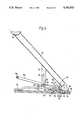
- FIG. 1is a diagrammatic side elevation in an aircraft passenger cabin illustrating the disposition of three seat rows
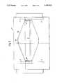
- FIG. 2is a cross section through a known seat rail installation illustrating the engagement of a seat leg therewith;
- FIG. 3is a cross sectional view taken on the line 3--3 in FIG. 2;
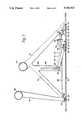
- FIG. 4is a side elevation of a rear leg, in accordance with a first embodiment of the invention, of the middle seating unit of the three rows illustrated in FIG. 1, in the position shown in solid lines;
- FIG. 5is a schematic plan view of the middle seat of the seating unit shown in FIG. 1, drawn as if the seat portion and its cushion were transparent;
- FIG. 6is an elevational view, similar to FIG. 4 but with the middle seating unit in the position illustrated in dotted lines in FIG. 1;
- FIG. 7is a side elevation of front and rear legs, in accordance with a second embodiment of the invention, of another seating unit similar to the middle seating unit of the three rows illustrated in FIG. 1, in the position shown in solid lines;
- FIG. 8is an elevational view, similar to FIG. 7 but with the middle seating unit in the position illustrated in dotted lines in FIG. 1.
- FIG. 1shows a portion of an aircraft passenger cabin having a floor 10, a ceiling 12 and three two-seat seating units 14, 16 and 18.
- the seating unit 16has two side frames, each comprising a front leg 20, and a rear leg 22, the two frames being interconnected by a transverse member 24.
- Each of the side framesis aligned with a respective seat rail mounted in the floor 10.
- the construction of each seat rail and the manner of attachment of the seat units theretois well known and is described, for example, in U.S. Pat. No. 4,856,738.
- each seat rail 30includes a longitudinal extending guideway slot 32. Throughout the length of the rail 30, equally spaced holes 34 extend vertically between the guideway slot and the seat rail upper surface 36, and longitudinal slots 38 interconnect the vertical holes 34.
- the slot 38 and the guideway slot 32are configured to conform substantially to the shoulder portion 40 of an attachment stud 42 which protrudes from each back leg 22 of the seating unit 16, and the holes 34 are of clearance diameter to accommodate the stud shoulder 40.
- a similar studprojects from each front leg.
- the seat railfurther includes side flanges 44 for seating floor panels 46 and a vertical flange 48 for attachment to a structural member 50 of the aircraft.
- the holes 34are equally spaced at one inch pitch and the studs on each seat unit are appropriately spaced to ensure conformity with the rail.
- To install and positively engage the seat on the railit is positioned at its desired fore and aft location such that the studs 42 locate in the corresponding holes 34, stud face 52 seating on the lower surface 54 of the guideway slot 32. Once positioned, the seat is moved forwards or rearwards as required until the shoulder surface 56 engages under the lip 58, that is at an intermediate position between two adjacent holes 34, resulting in positive engagement of the seat as indicated in FIG. 2.
- this method of connecting seats to floor railsis well known and does not form part of the present invention.
- FIG. 4shows the stud 42 on the bottom of the leg 22 in engagement with the rail 30.
- a plunger 60which is vertically movable relative to the leg 22 between an engaged positions (illustrated) and a release position. In the engaged position, it engages in the hole 34 immediately in front of the stud 42 so as to block movement of the stud 42 along the rail 30. In the release position, the plunger 60 is lifted clear of the rail 30, thereby freeing the stud 42 to slide.
- the plunger 60is coupled by a pivot pin 61 to a bell crank lever 62 which is coupled by a pivot pin 63 to a slider 64 which is mounted on a frame member 66 of the seating unit 16, the frame member 66 extending between the bottom of the rear leg 22 and the bottom of the corresponding front leg 20.
- a screw 68projects through a slot 70 in the slider 64 and engages in the frame member 66 so as to permit this sliding movement.
- the bell crank 62is mounted on a pivot pin 72 at the rear end of the member 66.
- a second stud 80also engages in the rail.
- the stud 80is connected to a bracket 82 which has a plunger 84, similar to the plunger 60 in that it is vertically movable relative to the bracket 82.
- the plunger 84is spring-biassed into its engaged position, as illustrated in FIG. 4 and can be displaced upwardly by means (not shown) to permit complete removal of the seating unit 16 from the aircraft.
- the plunger 84is permanently left in its engaged position to provide a fixed location for a pivot pin 85.
- a lever 86has one end coupled to the plunger 84 by the pivot pin 85. At its other end, the lever 86 carries a cam follower stud 88 which engages in a slot 90 in a vertical member 92 extending between the base member 66 and the leg 22. In its upper edge, the slider 64 has an open ended slot 96 which receives the cam follower stud 88 and the upper end of which is inclined rearwardly.
- the lever 86has a socket 98 which detachably receives a handle 100. As can be seen from FIG. 5, the handle 100 extends across the seat so as to engage with a similar socket 102 associated with the leg 22 on the other side, and has a central hand grip 104.
- the handle 100When it is desired to move the seat 16 from the position shown in solid lines in FIG. 1 to the position shown in dotted lines, the handle 100 is moved in a clockwise direction about the pivot point of the lever 86 on the bracket 82, raising the cam follower stud 88. As the stud 88 disengages from the slot 96 in the slider 64, it displaces the latter to the left, as viewed in FIG. 4, so that the bell crank lever 62 raises the plunger 60 out of engagement with the rail 30. Continued angular movement of the handle 100 causes the follower 88 to push the vertical member 92, and with it, the whole seat unit 16, rearwardly until it is at a position midway between the two positions illustrated in FIG.
- lever 100When it is desired to return the aircraft to its full-capacity daytime condition, the lever 100 is pivoted back to the position illustrated in FIG. 4.
- the lever 100is detachable. Preferably, it is removed when the aircraft is in use so as to leave unobstructed baggage storage space under the seats.
- the bell crank lever 62may be replaced by a cam system.
- FIGS. 7 and 8illustrate another embodiment of the invention comprising a seating unit having two side frames, each comprising a front leg 110, a rear leg 112 and a diagonal brace 114 interconnecting the top of the rear leg 112 and the bottom of the front leg 110.
- the two side framesare interconnected by a first transverse member 116 at the top of the front legs 110 and a rear transverse member 118 at the top of the rear legs 112.
- each of the side framesis aligned with a respective seat rail mounted in the aircraft floor, as illustrated in FIGS. 1 to 3.
- the bottom of the rear leg 112carries two studs 119 and 120 which are similar to the stud 42 of FIG. 1 and which are spaced apart from one another by a distance equal to the spacing between the holes 34 in the seat rails 30 (see FIG. 3).
- a T-shaped skid pad 122is secured to the stems of the studs 118 and 120 so that the stem of the T-shaped skid pad 122 projects into the slot 32 in the seat rail 30 and its cross-bar rests on the rail upper surface 36.
- the bottom of the front leg 110carries a similar stud 124.
- a similar T-shaped skid pad 126is slidably mounted on the shank of the stud 124 and biassed downwardly by Bellville washers 128.
- the bottoms of the front leg 110 and rear leg 112are interconnected by a frame member 130, similar to the frame member 66 of FIGS. 4 to 6.
- a slider 132similar to the slider 64, is mounted in slide guides 134 and 136 which are secured to the frame member 130.
- the slide guide 136 in the aisle-side framecarries a catch 138 which is spring biassed into a hole in the slider 132 so as to lock the latter in position, as will be explained hereinafter.
- the rear end of the slider 132is pivotally coupled to one arm of a bell-crank lever 140, which is journalled on a pivot pin 142 mounted on the frame member 130 and which has its other arm pivotally coupled to a plunger 144 which is dimensioned to engage in one of the holes 34 of the rail 30 in a similar manner to the plunger 60 of FIGS. 4 to 6.
- a further pair of studs 150 and 152also engage with the rail 30.
- the studs 150 and 152are mounted on a bracket 154 which also carries a plunger 156 which is vertically movable relative to the bracket 154 into and out of engagement with the rail to permit complete removal of the seating unit from the aircraft.
- the plunger 156is permanently secured in its engaged position relative to the bracket 154 by a clamping screw 157. The arrangement is thus similar to that of the plunger 84 of FIGS. 4 to 6.
- a lever 158On each side frame, a lever 158, similar to the lever 86 of FIGS. 4 to 6, has one end pivotally coupled to the bracket 154. At its other end, the lever 158 carries a cam follower stud 160 which engages in a slot 162 in a vertical member 164 extending between the frame member 130 and the diagonal brace 114.
- the front end of the slider 132has an open-ended slot 166 in its upper edge (similar to the slot 96 of FIGS. 4 to 6) which receives the cam follower stud 160.
- Angular movement of the levers 158 between the position shown in FIG. 7 and the position shown in FIG. 8moves the seat unit between a forward position, corresponding to the position of the seat 16 shown in solid lines in FIG. 1, to a rearward position similar to the position of the seat unit 16 shown in dotted lines in FIG. 1.
- the means for effecting angular movement of the levers 158differs from that illustrated in FIGS. 4 to 6.
- the two levers 158are interconnected at their lower ends by a torque rod 170 which extends across the bottom of the seat under the aircraft floor carpet.
- the torque rod 170is secured fast with the levers 158 and is journalled in the brackets 154.
- the torque rod 170At its end facing the aircraft aisle, the torque rod 170 has flat surfaces 172 which can be engaged by a detachable tool to effect the necessary angular movement.
- the spring loaded catch 138it is necessary to raise the spring loaded catch 138 so as to disengage its bottom end from the recess in the slider 132.
- FIGS. 7 and 8has the advantage that movement of the seat unit between its two positions can be effected from the aircraft aisle.
Landscapes
- Engineering & Computer Science (AREA)
- Aviation & Aerospace Engineering (AREA)
- Transportation (AREA)
- Mechanical Engineering (AREA)
- Seats For Vehicles (AREA)
Abstract
Description
This invention relates to adjustable passenger seating arrangement for vehicles, particularly aircraft.
Airlines require high utilization of their aircraft and it is uneconomic for an airliner to remain grounded for many hours in any twenty four hour period. However, the demand for seats on daytime flights is substantially greater than that for night flights. On the other hand, it is desirable to provide increased longitudinal spacing between seats on night flights so as to allow passengers to adopt a more comfortable sleeping position.
In an aircraft passenger cabin, it is commonplace for two or three passenger seats to be mounted on a common seat structure aligned and engaging longitudinally extending seat rails mounted on the floor or an underlying floor support structure. The seat-to-rail attachments generally comprise rail-engaging feet for resisting pitching forces, a deployable plunger for resisting fore and aft loads and an anti-rattle device to minimize or prevent chatter between the feet and the rail. Conventional feet comprise a shank portion engaging the seat structure terminating in a frusto-conical base portion engaging the rail. Each rail, of well known form, includes a passageway extending longitudinally therethrough whose lateral cross-section conforms substantially to the frusto-conical base portion and a series of equally spaced circular holes of diameter similarly conforming to that of the base portion extends between the passageway and the rail upper surface each pair of holes interconnected along a longitudinal centre line datum by a parallel slot of width at least equivalent to the foot shank diameter. This arrangement consequently provides a combination of circular apertures into which the feet are inserted and lips under which the frusto-conical base engages when the seat is moved forwards or rearwards one half pitch into locking engagement with the rail. The number of feet, associated with a particular seat assembly, depends on the loading characteristics but their fore and aft spacing will always conform with the rail configuration. Similarly, the fore and aft restraint usually a deployable plunger, is of diameter conforming to the circular aperture in the rail with which it is adjacently positioned in a fore and aft sense to engage when the feet are moved into locking engagement with the rail.
The present invention aims to provide a seating system having means for moving a seat structure through a predetermined distance in the fore and aft direction.
According to the invention, in an adjustable seating system for use in a passenger vehicle, a floor mounted seat rail extends longitudinally through at least a portion of a passenger carrying compartment and at least three seating units are mounted on said seat rail; the seat rail including a series of equally spaced interconnected openings along its length for fixedly engaging and retaining the seating units at any selected lengthwise location; at least one of the seating units including seat adjustment means comprising a plunger for engaging in said rail mounted on a leg of said seating unit for vertical movement between a rail engaging-position in which it engages with the rail to restrain fore and aft movement and a release position in which it permits fore and aft movement of the seating unit, a foot for engaging in said rail so as to resist both fore and aft movement and vertical movement, a lever pivotally mounted on the foot and having a cam follower engaging in vertically extending guide means secured to the seating unit, and coupling means responsive to displacement of the cam follower from the bottom of the guide means to move the plunger to its release position and adapted to return the plunger to its engaged position when the cam follower returns to the bottom of the guide means.
The cam follower is positionable at the bottom of the guide means either when the seating unit is in a first position in which the lever projects forwardly from the foot or when the seating unit is in a second position in which the lever projects rearwardly from the foot. The distance between these two positions is arranged to be a multiple of the spacing between the openings in the rail so that the plunger can move into its engaged position when the seating unit is in either of these two positions.
The lever may be provided with manually operable means, for example a detachable lever for causing pivotal movement relative to the plunger.
FIG. 1 is a diagrammatic side elevation in an aircraft passenger cabin illustrating the disposition of three seat rows;
FIG. 2 is a cross section through a known seat rail installation illustrating the engagement of a seat leg therewith;
FIG. 3 is a cross sectional view taken on theline 3--3 in FIG. 2;
FIG. 4 is a side elevation of a rear leg, in accordance with a first embodiment of the invention, of the middle seating unit of the three rows illustrated in FIG. 1, in the position shown in solid lines;
FIG. 5 is a schematic plan view of the middle seat of the seating unit shown in FIG. 1, drawn as if the seat portion and its cushion were transparent;
FIG. 6 is an elevational view, similar to FIG. 4 but with the middle seating unit in the position illustrated in dotted lines in FIG. 1;
FIG. 7 is a side elevation of front and rear legs, in accordance with a second embodiment of the invention, of another seating unit similar to the middle seating unit of the three rows illustrated in FIG. 1, in the position shown in solid lines; and
FIG. 8 is an elevational view, similar to FIG. 7 but with the middle seating unit in the position illustrated in dotted lines in FIG. 1.
FIG. 1 shows a portion of an aircraft passenger cabin having afloor 10, aceiling 12 and three two-seat seating units seating unit 16 has two side frames, each comprising afront leg 20, and arear leg 22, the two frames being interconnected by atransverse member 24. Each of the side frames is aligned with a respective seat rail mounted in thefloor 10. The construction of each seat rail and the manner of attachment of the seat units thereto is well known and is described, for example, in U.S. Pat. No. 4,856,738.
Referring to FIGS. 2 and 3, eachseat rail 30 includes a longitudinal extendingguideway slot 32. Throughout the length of therail 30, equally spaced holes 34 extend vertically between the guideway slot and the seat railupper surface 36, andlongitudinal slots 38 interconnect the vertical holes 34. Theslot 38 and theguideway slot 32 are configured to conform substantially to theshoulder portion 40 of anattachment stud 42 which protrudes from eachback leg 22 of theseating unit 16, and the holes 34 are of clearance diameter to accommodate thestud shoulder 40. A similar stud (not shown) projects from each front leg. The seat rail further includesside flanges 44 forseating floor panels 46 and avertical flange 48 for attachment to astructural member 50 of the aircraft.
The holes 34 are equally spaced at one inch pitch and the studs on each seat unit are appropriately spaced to ensure conformity with the rail. To install and positively engage the seat on the rail, it is positioned at its desired fore and aft location such that thestuds 42 locate in the corresponding holes 34,stud face 52 seating on thelower surface 54 of theguideway slot 32. Once positioned, the seat is moved forwards or rearwards as required until theshoulder surface 56 engages under thelip 58, that is at an intermediate position between two adjacent holes 34, resulting in positive engagement of the seat as indicated in FIG. 2. As already stated, this method of connecting seats to floor rails is well known and does not form part of the present invention.
FIG. 4 shows thestud 42 on the bottom of theleg 22 in engagement with therail 30. Immediately in front of thestud 42 is aplunger 60 which is vertically movable relative to theleg 22 between an engaged positions (illustrated) and a release position. In the engaged position, it engages in the hole 34 immediately in front of thestud 42 so as to block movement of thestud 42 along therail 30. In the release position, theplunger 60 is lifted clear of therail 30, thereby freeing thestud 42 to slide. In order to effect this vertical movement, theplunger 60 is coupled by apivot pin 61 to abell crank lever 62 which is coupled by apivot pin 63 to aslider 64 which is mounted on aframe member 66 of theseating unit 16, theframe member 66 extending between the bottom of therear leg 22 and the bottom of the correspondingfront leg 20. Ascrew 68 projects through aslot 70 in theslider 64 and engages in theframe member 66 so as to permit this sliding movement. Thebell crank 62 is mounted on apivot pin 72 at the rear end of themember 66.
In front of thestud 40, asecond stud 80 also engages in the rail. Thestud 80 is connected to abracket 82 which has aplunger 84, similar to theplunger 60 in that it is vertically movable relative to thebracket 82. However, theplunger 84 is spring-biassed into its engaged position, as illustrated in FIG. 4 and can be displaced upwardly by means (not shown) to permit complete removal of theseating unit 16 from the aircraft. In normal use, once installed, theplunger 84 is permanently left in its engaged position to provide a fixed location for apivot pin 85.
Alever 86 has one end coupled to theplunger 84 by thepivot pin 85. At its other end, thelever 86 carries acam follower stud 88 which engages in aslot 90 in avertical member 92 extending between thebase member 66 and theleg 22. In its upper edge, theslider 64 has an open ended slot 96 which receives thecam follower stud 88 and the upper end of which is inclined rearwardly. Thelever 86 has asocket 98 which detachably receives ahandle 100. As can be seen from FIG. 5, thehandle 100 extends across the seat so as to engage with asimilar socket 102 associated with theleg 22 on the other side, and has acentral hand grip 104.
When it is desired to move theseat 16 from the position shown in solid lines in FIG. 1 to the position shown in dotted lines, thehandle 100 is moved in a clockwise direction about the pivot point of thelever 86 on thebracket 82, raising thecam follower stud 88. As thestud 88 disengages from the slot 96 in theslider 64, it displaces the latter to the left, as viewed in FIG. 4, so that thebell crank lever 62 raises theplunger 60 out of engagement with therail 30. Continued angular movement of thehandle 100 causes thefollower 88 to push thevertical member 92, and with it, thewhole seat unit 16, rearwardly until it is at a position midway between the two positions illustrated in FIG. 1, when thehandle 100 is vertical and thestud 88 near the top of theslot 90. Further angular movement of thehandle 100 towards the position shown in FIG. 6 moves thestud 88 back down theslot 90 until finally it engages with the inclined slot 96 in theslider 64 to push theplunger 60 back into engagement with therail 58 to secure the seat in its new position, as illustrated in dotted lines in FIG. 1. In this position, the backrest of theseat 16 can be inclined almost to the horizontal, so that it lies on the seat cushion of theseat 18, and there is much more leg room between theseat 16 and theseat 14. Consequently, although theseat 18 cannot be occupied, the occupant of theseat 16 can be charged a higher fare in view of the more comfortable sleeping position provided by the invention.
When it is desired to return the aircraft to its full-capacity daytime condition, thelever 100 is pivoted back to the position illustrated in FIG. 4.
As already described, thelever 100 is detachable. Preferably, it is removed when the aircraft is in use so as to leave unobstructed baggage storage space under the seats.
If desired, the bell cranklever 62 may be replaced by a cam system.
FIGS. 7 and 8 illustrate another embodiment of the invention comprising a seating unit having two side frames, each comprising afront leg 110, arear leg 112 and adiagonal brace 114 interconnecting the top of therear leg 112 and the bottom of thefront leg 110. The two side frames are interconnected by a firsttransverse member 116 at the top of thefront legs 110 and a reartransverse member 118 at the top of therear legs 112. As with the first embodiment of the invention, each of the side frames is aligned with a respective seat rail mounted in the aircraft floor, as illustrated in FIGS. 1 to 3.
On each side frame, the bottom of therear leg 112 carries twostuds stud 42 of FIG. 1 and which are spaced apart from one another by a distance equal to the spacing between the holes 34 in the seat rails 30 (see FIG. 3). A T-shapedskid pad 122 is secured to the stems of thestuds skid pad 122 projects into theslot 32 in theseat rail 30 and its cross-bar rests on the railupper surface 36. The bottom of thefront leg 110 carries asimilar stud 124. A similar T-shapedskid pad 126 is slidably mounted on the shank of thestud 124 and biassed downwardly byBellville washers 128.
The bottoms of thefront leg 110 andrear leg 112 are interconnected by aframe member 130, similar to theframe member 66 of FIGS. 4 to 6. Aslider 132, similar to theslider 64, is mounted in slide guides 134 and 136 which are secured to theframe member 130. Theslide guide 136 in the aisle-side frame carries acatch 138 which is spring biassed into a hole in theslider 132 so as to lock the latter in position, as will be explained hereinafter.
The rear end of theslider 132 is pivotally coupled to one arm of a bell-crank lever 140, which is journalled on apivot pin 142 mounted on theframe member 130 and which has its other arm pivotally coupled to aplunger 144 which is dimensioned to engage in one of the holes 34 of therail 30 in a similar manner to theplunger 60 of FIGS. 4 to 6.
Between thefront stud 124 andrear studs studs rail 30. Thestuds bracket 154 which also carries aplunger 156 which is vertically movable relative to thebracket 154 into and out of engagement with the rail to permit complete removal of the seating unit from the aircraft. However, in normal use, theplunger 156 is permanently secured in its engaged position relative to thebracket 154 by a clampingscrew 157. The arrangement is thus similar to that of theplunger 84 of FIGS. 4 to 6.
On each side frame, alever 158, similar to thelever 86 of FIGS. 4 to 6, has one end pivotally coupled to thebracket 154. At its other end, thelever 158 carries acam follower stud 160 which engages in aslot 162 in avertical member 164 extending between theframe member 130 and thediagonal brace 114. The front end of theslider 132 has an open-endedslot 166 in its upper edge (similar to the slot 96 of FIGS. 4 to 6) which receives thecam follower stud 160.
Angular movement of thelevers 158 between the position shown in FIG. 7 and the position shown in FIG. 8 moves the seat unit between a forward position, corresponding to the position of theseat 16 shown in solid lines in FIG. 1, to a rearward position similar to the position of theseat unit 16 shown in dotted lines in FIG. 1. However, the means for effecting angular movement of thelevers 158 differs from that illustrated in FIGS. 4 to 6.
The twolevers 158 are interconnected at their lower ends by atorque rod 170 which extends across the bottom of the seat under the aircraft floor carpet. Thetorque rod 170 is secured fast with thelevers 158 and is journalled in thebrackets 154. At its end facing the aircraft aisle, thetorque rod 170 hasflat surfaces 172 which can be engaged by a detachable tool to effect the necessary angular movement. However, before theslider 132 on the aisle-side frame can move, it is necessary to raise the spring loadedcatch 138 so as to disengage its bottom end from the recess in theslider 132.
The embodiment illustrated in FIGS. 7 and 8 has the advantage that movement of the seat unit between its two positions can be effected from the aircraft aisle.
Claims (6)
1. An adjustable seating system, for use in a passenger vehicle, comprising a floor-mounted seat rail adapted to extend longitudinally through at least a portion of a passenger carrying compartment and at least three seating units mounted on said seat rail; the seat rail including a series of equally spaced interconnected openings along the length of said rail for fixedly engaging and retaining the seating units at any selected lengthwise location; at least one of the seating units including seat adjustment means comprising:
a first plunger for engaging in said rail mounted on a leg of said seating unit for vertical movement between a rail-engaging position in which said plunger engages with the rail to restrain fore and aft movement and a release position in which said first plunger permits fore and aft movement of the seating unit,
a second plunger for engaging in said rail so as to resist both fore and aft movement and vertical movement,
a lever pivotally mounted on the second plunger,
vertically extending guide means secured to the at least one seating unit,
a cam follower secured to said lever and engaging in said vertically extending guide means so as to be positionable at the bottom of the guide means either when the seating unit is in a first position in which the lever projects forwardly from the second plunger or when the seating unit is in a second position in which the lever projects rearwardly from the second plunger, the distance between these two positions being a multiple of the spacing between the opening in the rail so that the plunger can move into an engaged position when the seating unit is in either of these two positions, and
coupling means responsive to displacement of the cam follower from the bottom of the guide means to move the first plunger to the release position and adapted to return the first plunger to the rail-engaging position when the cam follower returns to the bottom of the guide means.
2. An adjustable seating system according to claim 1, wherein the lever is provided with manually operable means for causing pivotal movement relative to the plunger.
3. An adjustable seating system according to claim 2, wherein the manually operable means comprises a detachable lever.
4. An adjustable seating system according to claim 1, wherein the coupling means responsive to displacement of the cam follower comprises a horizontally moveable slider having a cam formation at one end and means connected to the plunger at an opposite end.
5. An adjustable seating system according to claim 4, wherein said means connected to the plunger comprises a bell-crank lever.
6. An adjustable seating system according to claim 4, wherein said cam formation comprises an open-ended slot, the cam follower being adapted to cause displacement of said slider during initial upward movement of the cam follower from the bottom of the guide means and to disengage from said open-ended slot during subsequent upward movement in which engagement of the cam follower with the guide means causes movement of the seating unit along the track.
Applications Claiming Priority (2)
| Application Number | Priority Date | Filing Date | Title |
|---|---|---|---|
| GB909013717AGB9013717D0 (en) | 1990-06-20 | 1990-06-20 | Adjustable passenger seating arrangement |
| GB9013717 | 1990-06-20 |
Publications (1)
| Publication Number | Publication Date |
|---|---|
| US5183313Atrue US5183313A (en) | 1993-02-02 |
Family
ID=10677896
Family Applications (1)
| Application Number | Title | Priority Date | Filing Date |
|---|---|---|---|
| US07/713,112Expired - LifetimeUS5183313A (en) | 1990-06-20 | 1991-06-10 | Two position adjustable passenger arrangement having cam, plunger, and pivoting lever |
Country Status (4)
| Country | Link |
|---|---|
| US (1) | US5183313A (en) |
| EP (1) | EP0463757B1 (en) |
| DE (1) | DE69104913T2 (en) |
| GB (1) | GB9013717D0 (en) |
Cited By (26)
| Publication number | Priority date | Publication date | Assignee | Title |
|---|---|---|---|---|
| US5662367A (en)* | 1994-09-02 | 1997-09-02 | Mercedes-Benz Ag | Removable motor vehicles rear seat |
| US5871318A (en)* | 1997-11-12 | 1999-02-16 | Be Aerospace, Inc. | Quick-release track fastener |
| US5913559A (en)* | 1997-03-19 | 1999-06-22 | Ferno-Washington, Inc. | Fastening track, cot transport vehicle adapted to secure the fastening track, and cot fastening system incorporating same |
| US5937706A (en)* | 1996-07-10 | 1999-08-17 | Nmi Safety Systems Limited | Carriage adapted to be slidably mounted on a track |
| US6189852B1 (en)* | 1996-09-06 | 2001-02-20 | Manchester Metropolitan University | Seating system |
| US6357715B1 (en)* | 1999-03-10 | 2002-03-19 | Nmi Safety Systems, Ltd. | Support for a vehicle seat |
| US20030234566A1 (en)* | 2002-06-25 | 2003-12-25 | Vanderminden William M. | Adjustable swivel rocker |
| US20040232283A1 (en)* | 2001-08-09 | 2004-11-25 | David Ferry | Seating system and a passenger accommodation unit for a vehicle |
| US20050106267A1 (en)* | 2003-10-20 | 2005-05-19 | Framework Therapeutics, Llc | Zeolite molecular sieves for the removal of toxins |
| US6902365B1 (en) | 2004-02-13 | 2005-06-07 | B E Aerospace, Inc. | Quick-release track fastener |
| US20050180836A1 (en)* | 2004-02-13 | 2005-08-18 | B E Aerospace, Inc. | Dual track fitting |
| US20060263164A1 (en)* | 2005-05-17 | 2006-11-23 | Be Aerospace, Inc. | Load-limiting and energy-dissipating mount for vehicle seating |
| USD583579S1 (en) | 2004-06-18 | 2008-12-30 | Virgin Atlantic Airways Limited | Airplane seating unit |
| US20090302665A1 (en)* | 2006-01-30 | 2009-12-10 | Mark Brian Dowty | Anti-rattle track fastener |
| US20110073742A1 (en)* | 2009-07-28 | 2011-03-31 | Attax | Attachment system for an aircraft seat |
| DE102012012686A1 (en)* | 2012-06-27 | 2014-01-02 | Eads Deutschland Gmbh | Seat arrangement with longitudinally displaceable seat rows |
| WO2015080944A1 (en)* | 2013-11-27 | 2015-06-04 | B/E Aerospace, Inc. | Method and apparatus for adjusting the spacing of vehicle seats based on the size of the occupant |
| US20150284095A1 (en)* | 2014-04-04 | 2015-10-08 | B/E Aerospace, Inc. | Aircraft seat base frame |
| US20170275003A1 (en)* | 2014-09-25 | 2017-09-28 | Bombardier Inc. | Aircraft seat |
| DE102016110057A1 (en)* | 2016-05-31 | 2017-11-30 | Airbus Operations Gmbh | Passenger seating system for a cabin of a means of transport |
| US9868531B2 (en) | 2014-03-28 | 2018-01-16 | Airbus Operations Gmbh | Passenger seat arrangement for a vehicle |
| US9919803B2 (en) | 2014-04-04 | 2018-03-20 | B/E Aerospace, Inc. | Aircraft seat base frame |
| US20190291616A1 (en)* | 2016-07-18 | 2019-09-26 | Safran Seats Usa Llc | Seat beam clamp |
| US10518885B2 (en) | 2011-10-07 | 2019-12-31 | Bombardier Inc. | Aircraft seat |
| CN111791761A (en)* | 2019-04-04 | 2020-10-20 | 沃尔沃汽车公司 | Lightweight C-Ring Crossmember and Bracket Assembly for Vehicles |
| US11136128B2 (en)* | 2016-11-16 | 2021-10-05 | Airbus Operations Gmbh | Aircraft seat kit, and aircraft seat and cabin arrangement with different types of seat rail adapters |
Families Citing this family (9)
| Publication number | Priority date | Publication date | Assignee | Title |
|---|---|---|---|---|
| GB9425078D0 (en)* | 1994-12-13 | 1995-02-08 | British Airways Plc | A seating unit |
| DE19547095C2 (en)* | 1995-12-16 | 2003-06-26 | Talbot Gmbh & Co Kg | Variable mounting arrangement for elements of an interior |
| GB2314012B (en)* | 1996-06-13 | 1999-01-13 | Michael Angelo Callard | A removable seat |
| FR2866315B1 (en)* | 2004-02-13 | 2007-04-20 | Airbus France | AIRCRAFT CAR SEAT RAIL AND METHOD OF MANUFACTURING SUCH A RAIL |
| DE102005049187A1 (en)* | 2005-10-14 | 2007-04-19 | Recaro Aircraft Seating Gmbh & Co. Kg | Seat fastening device |
| DE102005054890B4 (en) | 2005-11-17 | 2014-08-21 | Airbus Operations Gmbh | An aircraft fuselage structure with a passenger cabin and a mounting structure for fixing interior components in the passenger cabin |
| ATE474772T1 (en) | 2005-12-23 | 2010-08-15 | British Airways Plc | AIRCRAFT PASSENGER SEAT |
| FR2969232B1 (en)* | 2010-12-21 | 2013-01-04 | Sagem Defense Securite | ATTACHING BODY OF A BRACKET HAS A SLIDE AND BATI EQUIPPED WITH SUCH A BODY OF ATTACHE |
| US11427328B2 (en)* | 2019-03-29 | 2022-08-30 | The Boeing Company | Seat indexing systems and methods |
Citations (7)
| Publication number | Priority date | Publication date | Assignee | Title |
|---|---|---|---|---|
| US1735518A (en)* | 1927-01-03 | 1929-11-12 | Paralock Company | Vehicle seat |
| US4114947A (en)* | 1977-11-18 | 1978-09-19 | Chas. Olson & Sons | Detachable seat mounting for buses |
| US4396175A (en)* | 1980-12-08 | 1983-08-02 | Uop Inc. | Track fitting |
| US4723732A (en)* | 1985-09-12 | 1988-02-09 | The Boeing Company | Movable seating system for aircraft |
| US4856738A (en)* | 1987-03-07 | 1989-08-15 | British Aerospace Public Limited Company | Adjustable seating arrangement for aircraft |
| US4913489A (en)* | 1979-06-06 | 1990-04-03 | Tissmetal Lionel-Dupont | Device for varying the distance between the seats in commercial aircraft |
| US4936527A (en)* | 1985-09-12 | 1990-06-26 | The Boeing Company | Movable seating system for aircraft |
Family Cites Families (3)
| Publication number | Priority date | Publication date | Assignee | Title |
|---|---|---|---|---|
| US3620171A (en)* | 1969-12-04 | 1971-11-16 | Ancra Corp | Rattleproof tie-down assembly |
| US3605637A (en)* | 1970-09-02 | 1971-09-20 | Ancra Corp | Anchor fitting for securing loads to a retainer track |
| US4277043A (en)* | 1979-05-25 | 1981-07-07 | Koehler-Dayton, Inc. | Locking assembly for aircraft seat |
- 1990
- 1990-06-20GBGB909013717Apatent/GB9013717D0/enactivePending
- 1991
- 1991-06-07DEDE69104913Tpatent/DE69104913T2/ennot_activeExpired - Fee Related
- 1991-06-07EPEP91305156Apatent/EP0463757B1/ennot_activeExpired - Lifetime
- 1991-06-10USUS07/713,112patent/US5183313A/ennot_activeExpired - Lifetime
Patent Citations (7)
| Publication number | Priority date | Publication date | Assignee | Title |
|---|---|---|---|---|
| US1735518A (en)* | 1927-01-03 | 1929-11-12 | Paralock Company | Vehicle seat |
| US4114947A (en)* | 1977-11-18 | 1978-09-19 | Chas. Olson & Sons | Detachable seat mounting for buses |
| US4913489A (en)* | 1979-06-06 | 1990-04-03 | Tissmetal Lionel-Dupont | Device for varying the distance between the seats in commercial aircraft |
| US4396175A (en)* | 1980-12-08 | 1983-08-02 | Uop Inc. | Track fitting |
| US4723732A (en)* | 1985-09-12 | 1988-02-09 | The Boeing Company | Movable seating system for aircraft |
| US4936527A (en)* | 1985-09-12 | 1990-06-26 | The Boeing Company | Movable seating system for aircraft |
| US4856738A (en)* | 1987-03-07 | 1989-08-15 | British Aerospace Public Limited Company | Adjustable seating arrangement for aircraft |
Cited By (52)
| Publication number | Priority date | Publication date | Assignee | Title |
|---|---|---|---|---|
| US5662367A (en)* | 1994-09-02 | 1997-09-02 | Mercedes-Benz Ag | Removable motor vehicles rear seat |
| US5937706A (en)* | 1996-07-10 | 1999-08-17 | Nmi Safety Systems Limited | Carriage adapted to be slidably mounted on a track |
| US6189852B1 (en)* | 1996-09-06 | 2001-02-20 | Manchester Metropolitan University | Seating system |
| US5913559A (en)* | 1997-03-19 | 1999-06-22 | Ferno-Washington, Inc. | Fastening track, cot transport vehicle adapted to secure the fastening track, and cot fastening system incorporating same |
| US5871318A (en)* | 1997-11-12 | 1999-02-16 | Be Aerospace, Inc. | Quick-release track fastener |
| US6357715B1 (en)* | 1999-03-10 | 2002-03-19 | Nmi Safety Systems, Ltd. | Support for a vehicle seat |
| US9403597B2 (en) | 2001-08-09 | 2016-08-02 | Virgin Atlantic Airways Limited | Seating system and a passenger accommodation unit for a vehicle |
| US20040232283A1 (en)* | 2001-08-09 | 2004-11-25 | David Ferry | Seating system and a passenger accommodation unit for a vehicle |
| US7469861B2 (en) | 2001-08-09 | 2008-12-30 | Virgin Atlantic Airways Limited | Seating system and a passenger accommodation unit for a vehicle |
| US8720821B2 (en) | 2001-08-09 | 2014-05-13 | Virgin Atlantic Airways Limited | Seating system and passenger accommodation unit for a vehicle |
| US8313059B2 (en) | 2001-08-09 | 2012-11-20 | Virgin Atlantic Airways Limited | Seating system and a passenger accommodation unit for a vehicle |
| US7997654B2 (en) | 2001-08-09 | 2011-08-16 | Virgin Atlantic Airways Limited | Seating system and a passenger accommodation unit for a vehicle |
| US7523888B2 (en) | 2001-08-09 | 2009-04-28 | Virgin Atlantic Airways Limited | Seating system and a passenger accommodation unit for a vehicle |
| US7472957B2 (en) | 2001-08-09 | 2009-01-06 | Virgin Atlantic Airways Limited | Seating system and a passenger accommodation unit for a vehicle |
| US20070069073A1 (en)* | 2001-08-09 | 2007-03-29 | David Ferry | Seating system and a passenger accommodation unit for a vehicle |
| US20070080566A1 (en)* | 2001-08-09 | 2007-04-12 | David Ferry | Seating system and a passenger accommodation unit for a vehicle |
| US20030234566A1 (en)* | 2002-06-25 | 2003-12-25 | Vanderminden William M. | Adjustable swivel rocker |
| US6913317B2 (en)* | 2002-06-25 | 2005-07-05 | Telescope Casual Furniture, Inc. | Adjustable swivel rocker |
| US11083748B2 (en) | 2003-10-20 | 2021-08-10 | Framework Therapeutics, Llc | Zeolite molecular sieves for the removal of toxins |
| US10555969B2 (en) | 2003-10-20 | 2020-02-11 | Framework Therapeutics, Llc | Zeolite molecular sieves for the removal of toxins |
| US20050106267A1 (en)* | 2003-10-20 | 2005-05-19 | Framework Therapeutics, Llc | Zeolite molecular sieves for the removal of toxins |
| US7029215B2 (en) | 2004-02-13 | 2006-04-18 | Be Aerospace, Inc. | Dual track fitting |
| US20050180836A1 (en)* | 2004-02-13 | 2005-08-18 | B E Aerospace, Inc. | Dual track fitting |
| US6902365B1 (en) | 2004-02-13 | 2005-06-07 | B E Aerospace, Inc. | Quick-release track fastener |
| USD583579S1 (en) | 2004-06-18 | 2008-12-30 | Virgin Atlantic Airways Limited | Airplane seating unit |
| US7393167B2 (en) | 2005-05-17 | 2008-07-01 | Be Aerospace, Inc. | Load-limiting and energy-dissipating mount for vehicle seating |
| US20060263164A1 (en)* | 2005-05-17 | 2006-11-23 | Be Aerospace, Inc. | Load-limiting and energy-dissipating mount for vehicle seating |
| US8376306B2 (en)* | 2006-01-30 | 2013-02-19 | Be Aerospace, Inc. | Anti-rattle track fastener |
| US20090302665A1 (en)* | 2006-01-30 | 2009-12-10 | Mark Brian Dowty | Anti-rattle track fastener |
| US20110073742A1 (en)* | 2009-07-28 | 2011-03-31 | Attax | Attachment system for an aircraft seat |
| US8814126B2 (en)* | 2009-07-28 | 2014-08-26 | Attax | Attachment system for an aircraft seat |
| US10518885B2 (en) | 2011-10-07 | 2019-12-31 | Bombardier Inc. | Aircraft seat |
| US11130576B2 (en) | 2011-10-07 | 2021-09-28 | Bombardier Inc. | Aircraft seat |
| US10906649B2 (en) | 2011-10-07 | 2021-02-02 | Bombardier Inc. | Aircraft seat |
| DE102012012686B4 (en)* | 2012-06-27 | 2014-12-11 | Airbus Defence and Space GmbH | Aircraft with a number of rows of seat assemblies arranged longitudinally behind one another in the vehicle longitudinal direction with longitudinally displaceable seat rows, seat arrangement and their use |
| DE102012012686A1 (en)* | 2012-06-27 | 2014-01-02 | Eads Deutschland Gmbh | Seat arrangement with longitudinally displaceable seat rows |
| WO2015080944A1 (en)* | 2013-11-27 | 2015-06-04 | B/E Aerospace, Inc. | Method and apparatus for adjusting the spacing of vehicle seats based on the size of the occupant |
| US9868531B2 (en) | 2014-03-28 | 2018-01-16 | Airbus Operations Gmbh | Passenger seat arrangement for a vehicle |
| US20150284095A1 (en)* | 2014-04-04 | 2015-10-08 | B/E Aerospace, Inc. | Aircraft seat base frame |
| US9919803B2 (en) | 2014-04-04 | 2018-03-20 | B/E Aerospace, Inc. | Aircraft seat base frame |
| US9573688B2 (en)* | 2014-04-04 | 2017-02-21 | B/E Aerospace, Inc. | Aircraft seat base frame |
| US20170275003A1 (en)* | 2014-09-25 | 2017-09-28 | Bombardier Inc. | Aircraft seat |
| US10583926B2 (en)* | 2014-09-25 | 2020-03-10 | Bombardier Inc. | Aircraft seat |
| CN109311537A (en)* | 2016-05-31 | 2019-02-05 | 空中客车德国运营有限责任公司 | The passenger seat system in the cabin for means of transport |
| DE102016110057A1 (en)* | 2016-05-31 | 2017-11-30 | Airbus Operations Gmbh | Passenger seating system for a cabin of a means of transport |
| US11186375B2 (en)* | 2016-05-31 | 2021-11-30 | Airbus Operations Gmbh | Passenger seat system for a cabin of a means of transportation |
| US10737601B2 (en)* | 2016-07-18 | 2020-08-11 | Safran Seats Usa Llc | Seat beam clamp |
| US20190291616A1 (en)* | 2016-07-18 | 2019-09-26 | Safran Seats Usa Llc | Seat beam clamp |
| US11136128B2 (en)* | 2016-11-16 | 2021-10-05 | Airbus Operations Gmbh | Aircraft seat kit, and aircraft seat and cabin arrangement with different types of seat rail adapters |
| CN111791761A (en)* | 2019-04-04 | 2020-10-20 | 沃尔沃汽车公司 | Lightweight C-Ring Crossmember and Bracket Assembly for Vehicles |
| US10967760B2 (en)* | 2019-04-04 | 2021-04-06 | Volvo Car Corporation | Lightweight c-ring crossmember and bracket assembly for a vehicle |
| CN111791761B (en)* | 2019-04-04 | 2022-09-13 | 沃尔沃汽车公司 | Lightweight C-Ring Crossmember and Bracket Assemblies for Vehicles |
Also Published As
| Publication number | Publication date |
|---|---|
| GB9013717D0 (en) | 1990-08-08 |
| EP0463757A3 (en) | 1992-09-16 |
| EP0463757A2 (en) | 1992-01-02 |
| DE69104913D1 (en) | 1994-12-08 |
| DE69104913T2 (en) | 1995-03-23 |
| EP0463757B1 (en) | 1994-11-02 |
Similar Documents
| Publication | Publication Date | Title |
|---|---|---|
| US5183313A (en) | Two position adjustable passenger arrangement having cam, plunger, and pivoting lever | |
| EP0530923B1 (en) | Aircraft seat assembly | |
| US6478256B1 (en) | Passenger seat with seat back breakover assembly and method | |
| US4394047A (en) | Seat back mounting system | |
| US5857745A (en) | Vehicle seat | |
| US6669295B2 (en) | Passenger seat with low profile seat back recline locking assembly | |
| US6644738B2 (en) | Aircraft passenger seat frame construction | |
| EP1116654B1 (en) | Passenger sleeper seat | |
| US4512609A (en) | Arrangement in a vehicle seat | |
| US6749266B2 (en) | Locking collar for passenger seat back recline assembly | |
| EP0282244B1 (en) | Adjusting seating arrangement for aircraft | |
| US20030094542A1 (en) | Passenger seat, passenger seat leg module and method | |
| EP3680173B1 (en) | Passenger seat reconfigurable for seating or storage | |
| DE102005037405A1 (en) | vehicle seat | |
| DE69925978T2 (en) | A device for providing privacy protection and assistance to passengers in the cabin of a commercial aircraft | |
| US5288134A (en) | Seat assembly with integrated seat cushion and seat track frame | |
| US20230398909A1 (en) | Vehicle seat with a locking element | |
| US3880466A (en) | Forward-folding arm rest for vehicular seating | |
| US3193326A (en) | Automobile baby seat | |
| US5383704A (en) | Intermediate armrest for a row of seats | |
| US11312498B2 (en) | Convertible armrest disposed between adjacent seats | |
| US12187437B2 (en) | Economy class passenger seat with bed mode and removable cushion | |
| EP4330137B1 (en) | Aircraft seat assembly | |
| US10780807B1 (en) | Seat mounted adjustable lateral headrest | |
| US12049321B2 (en) | Aircraft bulkhead-mounted pilot seat with horizontal and vertical adjustment |
Legal Events
| Date | Code | Title | Description |
|---|---|---|---|
| AS | Assignment | Owner name:L.A. RUMBOLD LIMITED Free format text:ASSIGNMENT OF ASSIGNORS INTEREST.;ASSIGNOR:CUNNINGHAM, DOUGLAS J.;REEL/FRAME:005747/0078 Effective date:19910517 | |
| FEPP | Fee payment procedure | Free format text:PAYOR NUMBER ASSIGNED (ORIGINAL EVENT CODE: ASPN); ENTITY STATUS OF PATENT OWNER: LARGE ENTITY | |
| STCF | Information on status: patent grant | Free format text:PATENTED CASE | |
| AS | Assignment | Owner name:BRITAX RUMBOLD LIMITED, ENGLAND Free format text:CHANGE OF NAME;ASSIGNOR:L.A. RUMBOLD LIMITED;REEL/FRAME:008006/0940 Effective date:19960501 | |
| FPAY | Fee payment | Year of fee payment:4 | |
| FPAY | Fee payment | Year of fee payment:8 | |
| FPAY | Fee payment | Year of fee payment:12 | |
| AS | Assignment | Owner name:CONTOUR AEROSPACE LIMITED, UNITED KINGDOM Free format text:CHANGE OF NAME;ASSIGNOR:BRITAX RUMBOLD LIMITED;REEL/FRAME:027106/0103 Effective date:20110310 |