US5182779A - Device, system and process for detecting tensile loads on a rope having an optical fiber incorporated therein - Google Patents
Device, system and process for detecting tensile loads on a rope having an optical fiber incorporated thereinDownload PDFInfo
- Publication number
- US5182779A US5182779AUS07/506,034US50603490AUS5182779AUS 5182779 AUS5182779 AUS 5182779AUS 50603490 AUS50603490 AUS 50603490AUS 5182779 AUS5182779 AUS 5182779A
- Authority
- US
- United States
- Prior art keywords
- fiber
- optical
- rope
- fiber optic
- signal
- Prior art date
- Legal status (The legal status is an assumption and is not a legal conclusion. Google has not performed a legal analysis and makes no representation as to the accuracy of the status listed.)
- Expired - Fee Related
Links
- 238000000034methodMethods0.000titleclaimsdescription53
- 230000008569processEffects0.000titleclaimsdescription41
- 239000013307optical fiberSubstances0.000titleclaimsdescription37
- 239000000835fiberSubstances0.000claimsabstractdescription139
- 230000008859changeEffects0.000claimsabstractdescription11
- 238000012544monitoring processMethods0.000claimsabstractdescription9
- 230000003287optical effectEffects0.000claimsdescription74
- 238000000253optical time-domain reflectometryMethods0.000claimsdescription18
- 230000005670electromagnetic radiationEffects0.000claimsdescription9
- 238000001069Raman spectroscopyMethods0.000claimsdescription4
- 230000010287polarizationEffects0.000claimsdescription4
- 230000001427coherent effectEffects0.000claimsdescription3
- 238000005253claddingMethods0.000claimsdescription2
- 230000009977dual effectEffects0.000claimsdescription2
- 238000004519manufacturing processMethods0.000description12
- 239000000463materialSubstances0.000description12
- 238000005259measurementMethods0.000description11
- 238000005461lubricationMethods0.000description8
- 238000012545processingMethods0.000description6
- 230000001902propagating effectEffects0.000description6
- 238000005452bendingMethods0.000description5
- 238000000576coating methodMethods0.000description5
- 230000000737periodic effectEffects0.000description5
- 239000004065semiconductorSubstances0.000description5
- 239000000126substanceSubstances0.000description5
- 230000006870functionEffects0.000description4
- 238000004364calculation methodMethods0.000description3
- 238000002310reflectometryMethods0.000description3
- 230000003068static effectEffects0.000description3
- 238000012360testing methodMethods0.000description3
- NIXOWILDQLNWCW-UHFFFAOYSA-MAcrylateChemical compound[O-]C(=O)C=CNIXOWILDQLNWCW-UHFFFAOYSA-M0.000description2
- XEEYBQQBJWHFJM-UHFFFAOYSA-NIronChemical compound[Fe]XEEYBQQBJWHFJM-UHFFFAOYSA-N0.000description2
- 238000010521absorption reactionMethods0.000description2
- 230000008901benefitEffects0.000description2
- 239000007767bonding agentSubstances0.000description2
- 230000001419dependent effectEffects0.000description2
- 238000005516engineering processMethods0.000description2
- 230000007613environmental effectEffects0.000description2
- 239000011521glassSubstances0.000description2
- 150000002500ionsChemical class0.000description2
- 239000000314lubricantSubstances0.000description2
- 230000005449particle theoryEffects0.000description2
- 239000013615primerSubstances0.000description2
- 239000002987primer (paints)Substances0.000description2
- 238000005070samplingMethods0.000description2
- 239000000565sealantSubstances0.000description2
- 230000035945sensitivityEffects0.000description2
- JBRZTFJDHDCESZ-UHFFFAOYSA-NAsGaChemical compound[As]#[Ga]JBRZTFJDHDCESZ-UHFFFAOYSA-N0.000description1
- RYGMFSIKBFXOCR-UHFFFAOYSA-NCopperChemical compound[Cu]RYGMFSIKBFXOCR-UHFFFAOYSA-N0.000description1
- 229910001218Gallium arsenideInorganic materials0.000description1
- 239000004642PolyimideSubstances0.000description1
- -1additional filamentsSubstances0.000description1
- 238000004458analytical methodMethods0.000description1
- 238000013528artificial neural networkMethods0.000description1
- 230000005540biological transmissionEffects0.000description1
- 230000015572biosynthetic processEffects0.000description1
- 239000000919ceramicSubstances0.000description1
- 239000011248coating agentSubstances0.000description1
- 230000001149cognitive effectEffects0.000description1
- 238000010276constructionMethods0.000description1
- 239000000356contaminantSubstances0.000description1
- 229910052802copperInorganic materials0.000description1
- 239000010949copperSubstances0.000description1
- 230000003247decreasing effectEffects0.000description1
- 230000001934delayEffects0.000description1
- 238000001514detection methodMethods0.000description1
- 230000001627detrimental effectEffects0.000description1
- 229910003460diamondInorganic materials0.000description1
- 239000010432diamondSubstances0.000description1
- 230000009699differential effectEffects0.000description1
- 238000009826distributionMethods0.000description1
- 238000005246galvanizingMethods0.000description1
- 125000002887hydroxy groupChemical group[H]O*0.000description1
- 238000005286illuminationMethods0.000description1
- 239000012535impuritySubstances0.000description1
- 238000010348incorporationMethods0.000description1
- 230000003993interactionEffects0.000description1
- 229910052742ironInorganic materials0.000description1
- 229910052751metalInorganic materials0.000description1
- 239000002184metalSubstances0.000description1
- 150000002739metalsChemical class0.000description1
- 238000010606normalizationMethods0.000description1
- 238000010422paintingMethods0.000description1
- 239000006223plastic coatingSubstances0.000description1
- 229920001721polyimidePolymers0.000description1
- 238000007781pre-processingMethods0.000description1
- 230000000644propagated effectEffects0.000description1
- 230000005610quantum mechanicsEffects0.000description1
- 230000006798recombinationEffects0.000description1
- 238000005215recombinationMethods0.000description1
- 229910052594sapphireInorganic materials0.000description1
- 239000010980sapphireSubstances0.000description1
- 229910052710siliconInorganic materials0.000description1
- 239000010703siliconSubstances0.000description1
- 230000003595spectral effectEffects0.000description1
- 238000001228spectrumMethods0.000description1
- 230000002269spontaneous effectEffects0.000description1
- 230000006641stabilisationEffects0.000description1
- 238000011105stabilizationMethods0.000description1
- 230000007704transitionEffects0.000description1
- XLYOFNOQVPJJNP-UHFFFAOYSA-NwaterSubstancesOXLYOFNOQVPJJNP-UHFFFAOYSA-N0.000description1
- 238000004804windingMethods0.000description1
Images


Classifications
- G—PHYSICS
- G01—MEASURING; TESTING
- G01L—MEASURING FORCE, STRESS, TORQUE, WORK, MECHANICAL POWER, MECHANICAL EFFICIENCY, OR FLUID PRESSURE
- G01L5/00—Apparatus for, or methods of, measuring force, work, mechanical power, or torque, specially adapted for specific purposes
- G01L5/04—Apparatus for, or methods of, measuring force, work, mechanical power, or torque, specially adapted for specific purposes for measuring tension in flexible members, e.g. ropes, cables, wires, threads, belts or bands
- G01L5/10—Apparatus for, or methods of, measuring force, work, mechanical power, or torque, specially adapted for specific purposes for measuring tension in flexible members, e.g. ropes, cables, wires, threads, belts or bands using electrical means
- G01L5/105—Apparatus for, or methods of, measuring force, work, mechanical power, or torque, specially adapted for specific purposes for measuring tension in flexible members, e.g. ropes, cables, wires, threads, belts or bands using electrical means using electro-optical means
- D—TEXTILES; PAPER
- D07—ROPES; CABLES OTHER THAN ELECTRIC
- D07B—ROPES OR CABLES IN GENERAL
- D07B1/00—Constructional features of ropes or cables
- D07B1/14—Ropes or cables with incorporated auxiliary elements, e.g. for marking, extending throughout the length of the rope or cable
- D07B1/145—Ropes or cables with incorporated auxiliary elements, e.g. for marking, extending throughout the length of the rope or cable comprising elements for indicating or detecting the rope or cable status
- G—PHYSICS
- G01—MEASURING; TESTING
- G01B—MEASURING LENGTH, THICKNESS OR SIMILAR LINEAR DIMENSIONS; MEASURING ANGLES; MEASURING AREAS; MEASURING IRREGULARITIES OF SURFACES OR CONTOURS
- G01B11/00—Measuring arrangements characterised by the use of optical techniques
- G01B11/16—Measuring arrangements characterised by the use of optical techniques for measuring the deformation in a solid, e.g. optical strain gauge
- G01B11/18—Measuring arrangements characterised by the use of optical techniques for measuring the deformation in a solid, e.g. optical strain gauge using photoelastic elements
- G—PHYSICS
- G01—MEASURING; TESTING
- G01D—MEASURING NOT SPECIALLY ADAPTED FOR A SPECIFIC VARIABLE; ARRANGEMENTS FOR MEASURING TWO OR MORE VARIABLES NOT COVERED IN A SINGLE OTHER SUBCLASS; TARIFF METERING APPARATUS; MEASURING OR TESTING NOT OTHERWISE PROVIDED FOR
- G01D5/00—Mechanical means for transferring the output of a sensing member; Means for converting the output of a sensing member to another variable where the form or nature of the sensing member does not constrain the means for converting; Transducers not specially adapted for a specific variable
- G01D5/26—Mechanical means for transferring the output of a sensing member; Means for converting the output of a sensing member to another variable where the form or nature of the sensing member does not constrain the means for converting; Transducers not specially adapted for a specific variable characterised by optical transfer means, i.e. using infrared, visible, or ultraviolet light
- G01D5/32—Mechanical means for transferring the output of a sensing member; Means for converting the output of a sensing member to another variable where the form or nature of the sensing member does not constrain the means for converting; Transducers not specially adapted for a specific variable characterised by optical transfer means, i.e. using infrared, visible, or ultraviolet light with attenuation or whole or partial obturation of beams of light
- G01D5/34—Mechanical means for transferring the output of a sensing member; Means for converting the output of a sensing member to another variable where the form or nature of the sensing member does not constrain the means for converting; Transducers not specially adapted for a specific variable characterised by optical transfer means, i.e. using infrared, visible, or ultraviolet light with attenuation or whole or partial obturation of beams of light the beams of light being detected by photocells
- G01D5/353—Mechanical means for transferring the output of a sensing member; Means for converting the output of a sensing member to another variable where the form or nature of the sensing member does not constrain the means for converting; Transducers not specially adapted for a specific variable characterised by optical transfer means, i.e. using infrared, visible, or ultraviolet light with attenuation or whole or partial obturation of beams of light the beams of light being detected by photocells influencing the transmission properties of an optical fibre
- G01D5/35306—Mechanical means for transferring the output of a sensing member; Means for converting the output of a sensing member to another variable where the form or nature of the sensing member does not constrain the means for converting; Transducers not specially adapted for a specific variable characterised by optical transfer means, i.e. using infrared, visible, or ultraviolet light with attenuation or whole or partial obturation of beams of light the beams of light being detected by photocells influencing the transmission properties of an optical fibre using an interferometer arrangement
- G01D5/35309—Mechanical means for transferring the output of a sensing member; Means for converting the output of a sensing member to another variable where the form or nature of the sensing member does not constrain the means for converting; Transducers not specially adapted for a specific variable characterised by optical transfer means, i.e. using infrared, visible, or ultraviolet light with attenuation or whole or partial obturation of beams of light the beams of light being detected by photocells influencing the transmission properties of an optical fibre using an interferometer arrangement using multiple waves interferometer
- G01D5/35316—Mechanical means for transferring the output of a sensing member; Means for converting the output of a sensing member to another variable where the form or nature of the sensing member does not constrain the means for converting; Transducers not specially adapted for a specific variable characterised by optical transfer means, i.e. using infrared, visible, or ultraviolet light with attenuation or whole or partial obturation of beams of light the beams of light being detected by photocells influencing the transmission properties of an optical fibre using an interferometer arrangement using multiple waves interferometer using a Bragg gratings
- D—TEXTILES; PAPER
- D07—ROPES; CABLES OTHER THAN ELECTRIC
- D07B—ROPES OR CABLES IN GENERAL
- D07B2201/00—Ropes or cables
- D07B2201/20—Rope or cable components
- D07B2201/2095—Auxiliary components, e.g. electric conductors or light guides
- D07B2201/2096—Light guides
Definitions
- ropesrefers to rope, wire rope and cable.
- a ropeis a structural element which is fabricated from any collection of elongated members, such as filaments or fibers, which are manufactured into some type of a long, structural line which is relatively flexible and capable of carrying tensile loads.
- a non-exclusive list of definitions of various elongated members used in ropesincludes:
- Cordsare twisted into strands. This process is called "forming.” Sometimes, extra cords, yarns, and/or filaments (made from relatively flexible materials) are added during the forming process for internal lubrication in each strand. These extra cords, yarns, and/or filaments are commonly used during the fabrication of ropes that are subjected to relatively high flexural loads.
- Such fibershave been incorporated into laminated structures, commonly known as smart structures, the common characteristic to the earlier structures being their rigid (substantially inflexible) nature.
- the present inventionmakes use of the ability to monitor strains on an optical fiber to monitor loads on rope structures, by incorporating fiber optics with the rope structure.
- a ropewhich includes a plurality of elongated load-bearing members, wherein at least one of the elongated members is a fiber optic.
- a system for detecting stimulus on a ropeincludes a plurality of elongated members arranged in the shape of a rope, wherein at least one of the elongated members is a fiber optic; an input signal transmitter, such as a laser; and a signal monitor which monitors electromagnetic radiation exiting from the fiber optic and compares an observed set of characteristics of the exiting electromagnetic radiation to an expected set of characteristics.
- a process for detecting stimulus on a rope containing a fiber opticcomprising the steps of:
- Embodiments of the inventionare discussed herein based on electromagnetism, which includes the general wave theory and particle theory of light.
- the general wave theorycan be approximated by the ray (geometrical optics) theory of light or more rigorously by Maxwell's equations (wave theory) incorporating the proper boundary conditions.
- the particle theoryis best described by quantum mechanics, which is needed to explain the interactions among photons, electrons, ions, and atoms.
- empirical calibration/baseline relationships among the various physical changes in the environment of the inventionmay be developed with respect to the changes in transmitted/reflected light to calculate the desired monitoring of the specific event.
- the methods of baseline calculation disclosed hereinare given as examples and are not intended to represent every baseline calculation method that is within the scope of the invention.
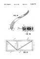
- FIG. 1Ashows an embodiment of the invention that is made as a common rope.
- FIG. 1Bshows an embodiment of the invention that is made as a selvage rope.
- FIG. 1Cshows a structural element whose loads are known through monitoring the loads on tension bearing members
- FIG. 2shows the basic components of a fiber optic.
- FIG. 3is a cross section of two media having different indices of refraction, showing reflection and refraction at the interface between the media when light travels from a higher to a lower refractive index medium.
- FIG. 4shows a fiber optic in which a light ray is traveling through the fiber optic at the critical angle for total internal reflection.
- FIG. 5shows the leakage of light from an optical fiber at a bend in the fiber.
- FIG. 6shows losses due to microbends in a fiber optic.
- FIG. 7Ashows a first mode or path in an optical fiber
- FIG. 7Bshows a second mode or path in an optical fiber.
- FIG. 8is a schematic of an embodiment of circuitry for use in the invention, including a signal monitor system.
- FIG. 9shows that Bragg gratings can be fabricated in optical fibers with differing peak reflectivities.
- FIG. 10shows dips in transmitted optical power at Bragg grating wavelengths.
- a selvage style ropeis a rope which is not fabricated by the commonly used twisting processes.
- a selvage ropeis fabricated by aligning a majority of its filaments or fibers parallel (with little or no twist) and constraining these filaments by wrapping small cords or ropes around them.
- FIG. 1Ashows an embodiment of the invention, manufactured as a common rope 1 having twisted strands 2 including a fiber optic 4.
- FIG. IBshows an embodiment of the invention manufactured as a selvage style rope having parallel elongated members 10, including fiber optic 12, and binding members 14, wrapped around elongated members 10.
- FIG. 1Cshows an example of a structural element in which loads on the structural element are known through monitoring the loads on tension bearing members.
- the structural elementis a truss 15, as might be used in the wing of an aircraft.
- Truss 15is made of rigid members 17, which are supported by rope 1.
- Rope 1contains fiber optic 4, as shown in FIG. 1A, and bears tension loads along its axis.
- a ropeis made by commingling the fiber optic sensors with structural filaments or fibers during the fabrication process of making yarns.
- the fiber optic sensorsare preformed to reduce or eliminate residual stresses which are created during the yarn making process. Preforming is the process of twisting an elongated member, such as a filament (or the like) in the opposite direction as the twisting process to make a cord, yarn, strand so that the elongated member is relatively untwisted in the manufactured cord, yarn, or strand.
- prestressing the ropehelps reduce the chance that the fiber optic will break before the rope reaches its maximum load.
- the commingling operation of incorporating fiber optic sensors with structural filamentscan be assisted by adding chemical lubricants as well as using chemical bonding agents, primers, sealants, or coatings. Additional filaments can be incorporated into the yarn to help improve the structural integrity of the yarn and to increase the service life of the fiber optic sensors. After the yarn is fabricated, the rest of the rope is manufactured by conventional means.
- the fiber optic sensorsare commingled with structural yarns during the fabrication process of making cords.
- the fiber optic sensors or yarnscan be preformed to reduce or eliminate residual stresses created during the cord making process.
- the incorporation of fiber optic sensors with structural yarnscan be assisted by adding chemical lubricants, bonding agents, primers, sealants, or coatings. Again, extra elongated members can be incorporated into the cord to help improve the structural integrity of the cord and to increase the service life of the fiber optic sensors.
- At least one fiber optic sensoris commingled with structural cords during the fabrication process of making strands.
- the fiber optic sensors or cordsare preformed to reduce or eliminate residual stresses.
- the commingling operationcan be assisted by adding chemicals, additional filaments, fibers, yarns, or cords.
- the fiber opticis commingled with structural strands while making the rope.
- the fiber optic sensors or strandsare preformed and the commingling can be assisted by adding chemicals as above. Additional filaments, fibers, yarns, cords, or strands also can be incorporated.
- wrapping, instead of commingling, the fiber optic sensors around elongated membersis the manufacturing technique.
- the fiber optic sensorsare commingled with non-structural filaments which are added for improved internal lubrication; the fiber optic sensors are wrapped around non-structural filaments that are added for improved internal lubrication; or the fiber optic is chemically bonded to the exterior of a yarn, cord, strand, or rope. For example, if one or more fiber optic sensors are bonded to a cord, then the remaining rope making processes would be unchanged. Likewise one or more fiber optic sensors can be bonded to the exterior of a rope.
- Embodiments of the inventionare also made using combinations of the above processes.
- one embodimentis fabricated with fiber optic sensors which are commingled with the structural fibers during the yarn making procedure, and have an additional set of fiber optics sensors commingled during the strand making procedure.
- other embodimentsare made where the fiber or elongated element is not preformed or prestressed.
- the sensing processbegins when some physical phenomenon (sometimes referred to as "physical parameters" or an “external parameter”) modifies light that is propagating in an optical fiber.
- physical parameterssometimes referred to as "physical parameters” or an “external parameter”
- the modified lightis usually detected and transformed to an electrical signal for convenience in later processing.
- the electrical or optical signalis compared to a reference quantity to determine qualities of the physical phenomenon such as spatial location, amplitude, frequency, and other parameters.
- Fiber optic sensor systemsare assembled from four basic categories of equipment: optical sources, optical fibers, optical detectors, and processing circuitry.
- the energy from common optical sourcescover a narrow band of optical frequencies having common center wavelengths, such as 780, 850, 1300, and 1550 nanometers.
- these sourcesproduce either unmodulated (continuous wave/CW) or modulated optical energy. Both of these types of sources are useful in sensing applications.
- the output of a modulated sourcecan vary in amplitude, frequency, or phase according to an applied electrical signal, while a CW source is fixed in these parameters.
- optical reflectometerstypically use pulses resulting from amplitude modulation of an optical source.
- Optical sourcesare also distinguished from one another by a characteristic known as coherence.
- Lightis “coherent” when it is in phase relative to all other light emerging from the optical source at that instant in time, and light is “incoherent” when it is out of phase relative to all other light emerging from the source at that time.
- optical sourcessuch as lasers are coherent, while optical sources such as light emitting diodes (LED's) are incoherent.
- LED's and lasersThe fundamental difference between LED's and lasers is the use of partially reflecting end surfaces and cavity walls in lasers. This allows for rapid building of light intensity in the recombination region. When the light intensity becomes sufficiently high, stimulated emission begins. In contrast, light emission in LED's take place in the spontaneous emission region. Much higher emitted power levels are available with the use of lasers and marginal increases in current.
- Optical sourcesemit light over a narrow range of frequencies. This range is determined by the semiconductors chosen for fabrication of the device. Lasers may be manufactured to emit light over a more narrow range of frequencies than LED's through use of tuned reflectors and distributed feedback.
- laser devicesproduce higher output power levels than LED's.
- lasersmay be more advantageous.
- LED'sare typically cheaper than lasers and simpler in construction, and because the current needed to sustain a stimulated emission condition is a function of temperature, temperature control equipment is often required to operate lasers. LED's usually require no temperature stabilization when operated in normal temperature ranges.
- Optical fibersconsist of layered cylinders of optical materials with extremely small diameters. Three layers are typically used as shown in FIG. 2.
- the central cylinder, called the core 20contains most of the optical energy in the fiber.
- Surrounding core 20is clad 22, which confines light to core 20 due to its slightly different optical properties.
- Enclosing jacket 24provides mechanical protection and support, but serves no optical function in most cases and is optional.
- a light ray 30is propagated through media 31 and 31' as follows.
- ⁇ 1When the angle of incidence of ray 30 at interface 36, ⁇ 1 , is large, part of ray 30 is reflected back into lower medium 31 (designated as ray 34) and part is transmitted into upper medium 31' (designated as ray 32).
- the relative intensities of rays 32 and 34are determined by a material quantity known as the refractive index.
- the refractive index of any particular mediumis defined as the ratio of velocity of light in a vacuum to the velocity of light in the medium.
- the refractive index of lower medium 31 in FIG. 3is denoted as n 1 while the refractive index of upper medium 31' is denoted as n 2 .
- the angle of ray 32 transmitted into upper medium 31'is denoted as ⁇ 2 and is determined by the indices of refraction for both materials according to Snell's law:
- the index of refraction of core 20is made slightly higher than the index of refraction of clad 22, so total internal reflection is attained for rays propagating at angles up to ⁇ c relative to core/clad interface 35.
- the first, material absorption,is due to the absorption of energy into the energy levels of impurities, such as iron, copper, or the like, as well as vibrational levels of hydroxyl and other ions that may be in core 20.
- the second type of attenuationis due to bending losses in the fiber. These bending losses may in turn be separated into losses due to larger, gradual bends (macrobends) and losses due to much smaller and sharper bends (microbends). Macrobends may result from winding the fiber on a small diameter mandrel or stringing it (as in a truss) with a small radius of curvature. Microbends arise because of random variations in direction of the core axis and may be due to external forces, ripples in the core or clad, or other causes.
- Fresnel reflectionsare comparatively very high level, usually due to breaks in the fiber.
- Rayleigh reflectionsare classically defined as occurring due to microscopic density fluctuations that are frozen into the core of the optical fiber as it cools after manufacture.
- Raman and Brillouin reflectionsare reflections from thermal photons and atomic quantum state transitions, respectively. These reflections are not usually significant until high optical intensities are used.
- macrobends and microbendscan be detected by measuring the total transmitted power.
- FIG. 5illustrates the way macrobends result in power loss.
- ray 50propagates at some angle ⁇ less than critical angle ⁇ c .
- ray 50is totally confined.
- the raywill intersect the core/clad interface 25 at some angle ⁇ ' that is greater than critical angle ⁇ c , so part of ray 50 will be transmitted out of core 20.
- power attenuationindicates the radius of curvature, so by measuring transmitted power through the fiber, the amount of bending is determined. For example, the more tight the bend, the greater the attenuation.
- benchmarks of the amount of attenuation for a particular amount of bendingare compared to actual measurements.
- FIG. 6illustrates the way microbends result in power loss.
- the microbendinduces ray angle ⁇ ' to be greater than critical angle ⁇ c at interface 25, so losses will occur, and assuming that the amount of macrobending is known, microbending is detected in one embodiment by measuring the transmitted power.
- microbends and macrobendsare measured by reflections back to the laser/LED.
- FIG. 7Ashows a cross section of a fiber where optical intensity may peak at the middle and taper toward the edges of core 20 for one mode, while the optical intensity may peak in the middle of the radius and go to zero at the center and edges of core 20 for another mode, shown in FIG. 7B.
- Light propagating along one path or mode of the fiberdoes not interact with light propagating in another path, unless there is an irregularity in the fiber.
- the irregularitymay be caused by any external parameter, such as strain. Therefore, by detecting the difference in optical characteristics between the modes when there is no external parameter and the modes in the presence of the external parameter, the external parameter is sensed.
- the optical characteristics monitoredare the interference patterns between the two modes.
- the amount of energy propagating in any given pathis dependent on fiber geometry, optical wavelength, optical polarization, and other conditions. Larger fibers tend to be multimode, while smaller fibers can be manufactured so that just one mode propagates, called single mode fibers.
- optical fibersMaterials used to manufacture the optical fibers will be chosen to meet mechanical strength and durability, as well as desired optical characteristics. Glass is commonly used for both the core and clad, along with an acrylate plastic coating. For higher temperature applications, materials such as sapphire or diamond can be substituted for the glass. Coatings such as polyimide and ceramic are commercially available for cases in which acrylate's strength and temperature resistance are not suitable. In addition, hermetic coatings may be applied to the surface of the fiber to seal the fiber against water and other contaminants.
- optical detectorsconvert optical energy from the fiber to electrical signals that are processed further.
- Most optical detectorsare made of silicon, while some are made of gallium arsenide.
- Commonly used detectorsare made of combinations of p-type (doped with excess holes), intrinsic (undoped), and n-type (doped with excess electrons) semiconductors.
- APDavalanche photodiodes
- variations in optical intensity due to a parameter to be sensedmay be extremely small. This would seem to indicate that a photon "amplifying" detector such as the APD should be used. In actual practice, APD's are highly dependent on temperature and tend to be “noisy” for low level optical signals. For this reason, a PIN diode is the detector of choice for some applications.
- the detectoris combined with a tunable optical interferometer, such as a Fabry-Perot interferometer.
- An interferometerlimits the optical energy received by the detector to a fine bandwidth in comparison to the total bandwidth of the optical energy and serves as an optical bandpass filter.
- Optical power at frequencies within the optical bandwidthis measured relative to power at other frequencies by retuning the interferometer. Measurements such as these allow for sensing of parameters such as strain and temperature in optical fibers which specifically alter the optical frequency as a function of the parameter measured.
- Processing circuitryincludes all hardware and software used to manipulate the electrical signals from the detector and convert them to meaningful sensor information.
- the processing circuitryincludes a signal monitor, such as a computer, with appropriate interfaces and software to collect the fiber optic sensor data; the electrical signal from the detector will be directly sampled and converted to a digital format for the computer.
- a signal monitorsuch as a computer
- a Fabry-Perot or other type of interferometerwill be used with a sample and hold circuit to sample detector voltage to yield optical intensity versus frequency information.
- a detected signalis compared to a reference (calibration) "baseline" in order to attach meaning to the signal.
- the baselinesare developed by computer-based cognitive methods such as neural networks.
- the baselinesare developed through measurement.
- baselinesrefer to an expected set of characteristics of the sensed transmitted or reflected signal.
- an example of a baselineis the transmitted power of a light signal through the fiber in an unloaded state.
- an example of a baselineis a periodic transmitted signal in an unloaded state.
- the baselineis stored in memory to be compared with measurements during operation of the system to detect the static or dynamic external parameter. In other embodiments, the baseline is not stored. For example, if two cores are included in one cladding, the difference in transmitted power between the two cores is the baseline. As a dynamic load is applied to the rope, the difference in the transmitted power between the two cores will change, resulting in detection of the dynamic load.
- the hardwarewill no longer be able to make timely comparisons of sensed optical signals to reference baselines due to high required throughput rates.
- pre-preprocessing of sensor datais used to alleviate this problem to some degree.
- Fourier transformsare used to generate spectral-domain (magnitude and phase) information from large quantities of sampled, time-domain data.
- Baselinesmay describe quantities such as desired magnitude and phase at a specific frequency or a magnitude "band" in which all data should lie.
- other domains and transforms to these domainsmay be used to decrease processing throughput requirements.
- loadsare monitored directly.
- quantitiessuch as temperature and pressure, are measured simultaneously.
- Loadsare applied axially, radially, torsionally, or in combinations of the preceding with respect to the optical fiber. These loads are either static, random, or periodic with respect to time. If it is desired to characterize random or periodic loads, the Nyquist criterion will determine sampling rate requirements. This criterion states that if a waveform is to be reconstructed after sampling, that waveform must be sampled at twice the fundamental frequency. For example, a 30 Hertz (Hz) periodic load must be sampled at 60 Hz to allow later reconstruction and analysis.
- HzHertz
- loadscan vary over the length of the optical fiber (spatially).
- Processes that may be used to sense loadsinclude:
- OTDROptical Time Domain Reflectometry
- laser transmitter 80 and optical receiver 82are attached to test fiber 84 through coupler 86.
- laser transmitter 80transmits light into test fiber 84 via coupler 86
- optical receiver 82receives the reflections created by breaks or other loads on fiber 84.
- Optical receiver 82converts the light received into electrical signals which are then sampled by electrical sampler 88.
- delays in time between transmission and reception of an optical pulsecorrespond to a specific location on the fiber.
- electrical sampler 88is controlled by time delay generator 90 so that time delay generator 90 turns on electrical sampler 88 to sample any reflections that have had time to reflect from a given point in fiber 84. For example, if it is desired to detect breaks at a distance d from transmitter 80, time delay generator 90 turns on sampler 88 after the pulse has had time to travel a distance of 2d.
- Processor 92in some embodiments, comprises a computer, which receives information regarding the reflections from electrical sampler 88. In one embodiment, processor 92 also comprises a means for comparing signals to baselines stored in a memory and a means for displaying the result of that comparison.
- processor 92comprises an OTDR which displays a trace of reflected power divided by baseline power on one axis, and distance on the other axis. When a break occurs, there is a peak in the display.
- time delay generator 90triggers transmitter 80 and sampler 88 in a sequence such that the entire length of fiber 84 is scanned for breaks.
- test fiber 84is included in a rope structure, wherein both ends of the optical fiber will produce Fresnel reflections. If the index of refraction for the core is known, as well as physical dimensions of the core such as cross-sectional area, and the elapsed time between reflections is known, the length of the fiber is calculated. Applied axial load is calculated if modulus of the fiber is known and data from an unstressed OTDR optical fiber measurement is stored as a baseline. Normalization of the loaded OTDR data by the baseline OTDR data will result in peaks, corresponding to areas of increased reflection amplitude over the baseline. Precision of this measurement is determined by optical pulse width. The shorter the pulse, the more accurate the measurement of amount of strain will be at a given location in the fiber.
- ⁇the stress applied to the fiber over the splice length
- ⁇the strain applied to the fiber over the splice length due to the load.
- ⁇ Xthe change in fiber length between a loaded and unloaded state
- Xthe fiber length in the unloaded state.
- Axial loadis related to stress by the formula:
- Athe area of the core of the fiber.
- splicesthat are periodic along the optical fiber. Since this is true, a length of spliced fiber may be fabricated to monitor loads at fine intervals in some sections and large intervals in other sections, corresponding to areas of high structural concern and low structural concern respectively. Since each splice reflects some quantity of optical power, input optical power will increase as the number of sensed locations increases.
- macrobends in an optical fibermay be used in exactly the same sense as splices to determine axial loads in sections between the macrobends.
- Macrobendsare typically introduced by running the rope through a stringer, pulley, or other relatively circular form with a small enough radius of curvature. Each macrobend will produce a drop in reflected optical intensity. Since these drops will usually be small in magnitude, a technique called "photon counting" increase detector sensitivity.
- An example of the photon counting processis disclosed in Garside, B.K., "A Photon Counting Optical Time-Domain Reflectometer for Distributed Sensing Applications.” B. K. Garside and R. E.
- microbends in an optical fibermay be used to determine axial loads in an optical fiber similar to macrobends and splices. Microbends are typically induced through pressure applied by crossing structural fibers in the braid of the rope, or other spatially "sharp" loads. As in macrobends, each microbend will produce a drop in reflected optical intensity, and photon-counting is used in this embodiment to detect the drop in intensity.
- Bragg gratingsare induced at semi-discrete locations in the fiber and used in the same way as splices with an OTDR.
- the Bragg gratings used in this embodimentare essentially partially reflective mirrors over a narrow range of wavelengths.
- the gratingsare induced using a high-powered ultraviolet (UV) laser with properly doped fiber.
- UVultraviolet
- the gratingsare produced after illumination by the UV laser through the fiber "wall,” as described in Meltz, et al., "Formation of Bragg Gratings In Optical Fibers By a Transverse Holographic Method," Optical Letters, Vol. 14, No. 15, p. 823 (Aug. 1, 1989).
- Bragg gratingsare fabricated in optical fibers with differing peak reflectivities as shown in FIG. 9.
- a particular gratingmay be made highly reflective at a specific wavelength and highly transmissive at other wavelengths. If different gratings are fabricated in a fiber with slightly differing reflective wavelengths, this fiber may be used as a sensor.
- a broadband (several contiguous wavelength) sourceis "launched" into one end of the fiber. If the opposite end of the fiber is connected to an optical spectrum analyzer covering the proper band of wavelengths, dips in optical power will appear at each Bragg grating wavelength as shown in FIG. 10.
- ⁇the stress applied to the fiber at the Bragg grating due to the load
- ⁇the strain applied to the fiber across the Bragg grating due to the load.
- ⁇the change in the wavelength of the peak for a particular grating between a loaded and unloaded state
- Ka proportionality constant
- Axial loadis related to stress by the formula:
- Athe area of the core of the fiber.
- optical fibersare produced with closely located cores.
- Optical energy propagating through the coresoscillates from one core to the other as a result of phase interference and other phenomena.
- Stimuli which have differential effects on the two fiberscan be distinguished by forming a ratio of the amount of power in one core relative to the other at the optical output. These stimuli include axial strain, radial strain, and temperature.
- multimode fibersare used in which light propagates through the fiber in different modes or paths, where these modes do not naturally interfere. These modes may be polarization, spatial, or other types of modes. Changes in interference between modes indicate environmental parameters to be monitored. This interference is due to phase differences induced in the two separate modes by such factors as slight differences in indices of refraction.
- a rope containing a fiber opticmay be used as a tensile load bearing member in a truss or wing of an aircraft. Strain and loads on the truss or wing may be indirectly monitored by monitoring the load on the fiber optic.
- the inventioncan be applied to other structural applications such as bridge cables, elevator cables, cranes, boom trusses, electrical power distribution cables, ski lifts, and lightweight space structures.
Landscapes
- Physics & Mathematics (AREA)
- General Physics & Mathematics (AREA)
- Length Measuring Devices By Optical Means (AREA)
Abstract
Description
cos(Θ.sub.2)=n.sub.1 cos(Θ.sub.1)/n.sub.2
σ=Yε
L=Aσ
σ=Yε
L=A σ
Claims (38)
Priority Applications (1)
| Application Number | Priority Date | Filing Date | Title |
|---|---|---|---|
| US07/506,034US5182779A (en) | 1990-04-05 | 1990-04-05 | Device, system and process for detecting tensile loads on a rope having an optical fiber incorporated therein |
Applications Claiming Priority (1)
| Application Number | Priority Date | Filing Date | Title |
|---|---|---|---|
| US07/506,034US5182779A (en) | 1990-04-05 | 1990-04-05 | Device, system and process for detecting tensile loads on a rope having an optical fiber incorporated therein |
Publications (1)
| Publication Number | Publication Date |
|---|---|
| US5182779Atrue US5182779A (en) | 1993-01-26 |
Family
ID=24012892
Family Applications (1)
| Application Number | Title | Priority Date | Filing Date |
|---|---|---|---|
| US07/506,034Expired - Fee RelatedUS5182779A (en) | 1990-04-05 | 1990-04-05 | Device, system and process for detecting tensile loads on a rope having an optical fiber incorporated therein |
Country Status (1)
| Country | Link |
|---|---|
| US (1) | US5182779A (en) |
Cited By (89)
| Publication number | Priority date | Publication date | Assignee | Title |
|---|---|---|---|---|
| US5283429A (en)* | 1992-09-10 | 1994-02-01 | Leviton Manufacturing Co., Inc. | Fiber optical monitoring system for eletrical conductors and the like |
| US5309533A (en)* | 1991-12-11 | 1994-05-03 | Thomson-Csf | Structure with intrinsic damage control, manufacturing processes and method of use |
| WO1994017366A1 (en)* | 1993-01-29 | 1994-08-04 | United Technologies Corporation | Active multipoint fiber laser sensor |
| WO1996031756A1 (en)* | 1995-04-04 | 1996-10-10 | Cambridge University Technical Services Limited | Optical fibre sensor |
| EP0785163A3 (en)* | 1996-01-22 | 1997-12-29 | Dennis St. Germain | Roundsling construction comrising a fiber optic signal strand |
| US5760391A (en)* | 1996-07-17 | 1998-06-02 | Mechanical Technology, Inc. | Passive optical wavelength analyzer with a passive nonuniform optical grating |
| USH1813H (en)* | 1993-11-19 | 1999-11-02 | Kersey; Alan D. | Spectrally-selective fiber transmission filter system |
| US6004639A (en)* | 1997-10-10 | 1999-12-21 | Fiberspar Spoolable Products, Inc. | Composite spoolable tube with sensor |
| US6276215B1 (en)* | 1997-12-05 | 2001-08-21 | Optoplan As | Sensor for measuring strain |
| WO2002055958A1 (en)* | 2001-01-11 | 2002-07-18 | Canadian Space Agency | Topological and motion measuring tool |
| US6466716B1 (en)* | 2000-08-24 | 2002-10-15 | Cidra Corporation | Optical fiber having a bragg grating in a wrap that resists temperature-induced changes in length |
| WO2002057805A3 (en)* | 2000-06-29 | 2002-10-17 | Paulo S Tubel | Method and system for monitoring smart structures utilizing distributed optical sensors |
| US6485376B1 (en)* | 2000-03-31 | 2002-11-26 | Mizuno Corporation | Golf club shaft |
| US20020185188A1 (en)* | 2001-04-27 | 2002-12-12 | Quigley Peter A. | Composite tubing |
| US6541758B2 (en)* | 2001-03-15 | 2003-04-01 | Ntt Advanced Technology Corporation | Liquid-level gauge |
| US20030087052A1 (en)* | 2001-11-05 | 2003-05-08 | Wideman Thomas W. | Spoolable composite tubing with a catalytically cured matrix |
| US20030121729A1 (en)* | 2002-01-02 | 2003-07-03 | Guenther Heinz | Lift belt and system |
| US6604550B2 (en) | 1995-09-28 | 2003-08-12 | Fiberspar Corporation | Composite spoolable tube |
| US20030174924A1 (en)* | 2002-03-14 | 2003-09-18 | Tennyson Roderick C. | Monitoring of large structures using brillouin spectrum analysis |
| US20040003856A1 (en)* | 2002-03-29 | 2004-01-08 | Quigley Peter A. | Systems and methods for pipeline rehabilitation |
| US20040083808A1 (en)* | 2002-11-06 | 2004-05-06 | Rambow Frederick Henry Kreisler | Apparatus and method for monitoring compaction |
| US20040120638A1 (en)* | 2002-12-18 | 2004-06-24 | Frick Roger L | Tunable optical filter |
| US20040206187A1 (en)* | 2003-01-23 | 2004-10-21 | Williams Jerry Gene | Performance monitoring of offshore petroleum risers using optical strain sensors |
| US20040233458A1 (en)* | 2000-11-28 | 2004-11-25 | Rosemount, Inc. | Electromagnetic resonant sensor |
| US20050002733A1 (en)* | 1997-03-07 | 2005-01-06 | Deep Water Composites As | Tension member termination |
| US20050063444A1 (en)* | 2000-11-28 | 2005-03-24 | Frick Roger L. | Optical sensor for measuring physical and material properties |
| US20050189029A1 (en)* | 2004-02-27 | 2005-09-01 | Fiberspar Corporation | Fiber reinforced spoolable pipe |
| US20050226584A1 (en)* | 2002-05-03 | 2005-10-13 | Williams Jerry G | Measurement of large strains in ropes using plastic optical fibers |
| US20050231207A1 (en)* | 2004-03-10 | 2005-10-20 | Dan Goldwater | Electronic elongation-sensing rope |
| WO2005098385A1 (en)* | 2004-04-08 | 2005-10-20 | Council For The Central Laboratory Of The Research Councils | Optical sensor |
| US7142737B1 (en)* | 2005-01-12 | 2006-11-28 | Network Integrity Systems Inc. | Intrusion detection system for use on single mode optical fiber using a storage register for data |
| CN100342076C (en)* | 2003-09-03 | 2007-10-10 | 欧进萍 | Optical fiber grating intelligent dragline |
| US20080006337A1 (en)* | 2006-03-22 | 2008-01-10 | Quigley Peter A | Dual Containment Systems, Methods and Kits |
| US20080006338A1 (en)* | 2006-03-21 | 2008-01-10 | Wideman Thomas W | Reinforcing Matrix for Spoolable Pipe |
| US20080185042A1 (en)* | 2007-02-02 | 2008-08-07 | Michael Feechan | Multi-cell spoolable composite pipe |
| US20080292262A1 (en)* | 2005-07-20 | 2008-11-27 | Wayne Cheatle | Grease-Free Buffer Optical Fiber Buffer Tube Construction Utilizing a Water-Swellable, Texturized Yarn |
| WO2009049616A2 (en) | 2007-10-19 | 2009-04-23 | Geo. Gleistein & Sohn Gmbh | Cable with electrical conductor included therein |
| US20090107558A1 (en)* | 2007-10-23 | 2009-04-30 | Quigley Peter A | Heated pipe and methods of transporting viscous fluid |
| US20090185772A1 (en)* | 2008-01-22 | 2009-07-23 | General Electric Company | Fiberoptic patient health multi-parameter monitoring devices and system |
| US20090278348A1 (en)* | 1995-09-28 | 2009-11-12 | Brotzell Arthur D | Composite coiled tubing end connector |
| EP1817556A4 (en)* | 2004-11-09 | 2010-01-20 | Woven Electronics Corp A South | Apparatus and method for a computerized fiber optic security system |
| US20100218944A1 (en)* | 2009-01-23 | 2010-09-02 | Quigley Peter A | Downhole fluid separation |
| CN101845763A (en)* | 2010-04-07 | 2010-09-29 | 金文成 | Distributed intelligent rope and manufacturing method thereof |
| US20110088462A1 (en)* | 2009-10-21 | 2011-04-21 | Halliburton Energy Services, Inc. | Downhole monitoring with distributed acoustic/vibration, strain and/or density sensing |
| US20110090496A1 (en)* | 2009-10-21 | 2011-04-21 | Halliburton Energy Services, Inc. | Downhole monitoring with distributed optical density, temperature and/or strain sensing |
| EP2345755A1 (en) | 2010-01-16 | 2011-07-20 | Klaus Bloch | Method for manufacturing carrier tissue and carrier tissue |
| US20110210542A1 (en)* | 2010-02-23 | 2011-09-01 | Makselon Christopher E | Connector for Spoolable Pipe |
| US20120085531A1 (en)* | 2010-10-07 | 2012-04-12 | Leising Larry J | Cable Monitoring in Coiled Tubing |
| WO2013035010A1 (en)* | 2011-09-09 | 2013-03-14 | Koninklijke Philips Electronics N.V. | Optical monitoring device for monitoring curvature of a flexible medical instrument |
| WO2013110853A1 (en)* | 2012-01-24 | 2013-08-01 | Kone Corporation | A rope of a lifting device, a rope arrangement, an elevator and a condition monitoring method for the rope of a lifting device |
| US8505625B2 (en) | 2010-06-16 | 2013-08-13 | Halliburton Energy Services, Inc. | Controlling well operations based on monitored parameters of cement health |
| WO2013131549A1 (en)* | 2012-03-05 | 2013-09-12 | Prysmian S.P.A. | Method for detecting torsion in a cable, electric cable with torsion sensor and method for manufacturing said cable |
| US20130239649A1 (en)* | 2010-09-15 | 2013-09-19 | Catenary Testing Limited | Method of determining the tension in a mooring line |
| US8584519B2 (en) | 2010-07-19 | 2013-11-19 | Halliburton Energy Services, Inc. | Communication through an enclosure of a line |
| CN103604384A (en)* | 2013-11-14 | 2014-02-26 | 南京大学 | Distributed fiber monitoring method and system for strains and stresses of ship lock structure |
| JP2014506670A (en)* | 2011-01-28 | 2014-03-17 | コーニンクレッカ フィリップス エヌ ヴェ | 3D shape reconstruction for optical tracking of elongated devices |
| US8678042B2 (en) | 1995-09-28 | 2014-03-25 | Fiberspar Corporation | Composite spoolable tube |
| US8746289B2 (en) | 2007-02-15 | 2014-06-10 | Fiberspar Corporation | Weighted spoolable pipe |
| US8893785B2 (en) | 2012-06-12 | 2014-11-25 | Halliburton Energy Services, Inc. | Location of downhole lines |
| US20140345978A1 (en)* | 2012-03-22 | 2014-11-27 | Kone Corporation | Travelling cable of an elevator, and an elevator |
| US8930143B2 (en) | 2010-07-14 | 2015-01-06 | Halliburton Energy Services, Inc. | Resolution enhancement for subterranean well distributed optical measurements |
| US8955599B2 (en) | 2009-12-15 | 2015-02-17 | Fiberspar Corporation | System and methods for removing fluids from a subterranean well |
| EP2843128A1 (en) | 2013-09-03 | 2015-03-04 | Teijin Aramid B.V. | Synthetic tracking fiber |
| WO2015109079A1 (en)* | 2014-01-15 | 2015-07-23 | Slingmax, Inc. | Rope pre-failure warning indicator system and method |
| US9206676B2 (en) | 2009-12-15 | 2015-12-08 | Fiberspar Corporation | System and methods for removing fluids from a subterranean well |
| US9388686B2 (en) | 2010-01-13 | 2016-07-12 | Halliburton Energy Services, Inc. | Maximizing hydrocarbon production while controlling phase behavior or precipitation of reservoir impairing liquids or solids |
| US20170010180A1 (en)* | 2014-04-03 | 2017-01-12 | Halliburton Energy Services, Inc. | Composite slickline cable integrity testing |
| JP2017044925A (en)* | 2015-08-27 | 2017-03-02 | 新日鉄住金エンジニアリング株式会社 | Cable and method of introducing initial tensile strain to optical fiber |
| CN106544912A (en)* | 2016-11-07 | 2017-03-29 | 北京恒润生工程科技有限公司 | Smart stay cable based on fiber Mach -Zehnder interferometer and preparation method thereof |
| AT518541B1 (en)* | 2016-05-09 | 2017-11-15 | Teufelberger Seil Ges M B H | steel cable |
| US9823373B2 (en) | 2012-11-08 | 2017-11-21 | Halliburton Energy Services, Inc. | Acoustic telemetry with distributed acoustic sensing system |
| US9857249B2 (en)* | 2013-03-15 | 2018-01-02 | Transocean Sedco Forex Ventures Limited | Tensioner load measurement system |
| US9890880B2 (en) | 2012-08-10 | 2018-02-13 | National Oilwell Varco, L.P. | Composite coiled tubing connectors |
| US20180171778A1 (en)* | 2014-06-30 | 2018-06-21 | Commonwealth Scientific And Industrial Research Organisaton | Deformation measurement method and apparatus |
| EP2029993B1 (en)* | 2006-05-17 | 2018-09-05 | BAM Bundesanstalt für Materialforschung und -prüfung | Reinforcement element with sensor fiber, monitoring system, and monitoring method |
| DE102018205722A1 (en)* | 2018-04-16 | 2019-10-17 | Siemens Aktiengesellschaft | Distance measurement by reflectometry in optical waveguides |
| CN113086876A (en)* | 2021-04-06 | 2021-07-09 | 武汉港迪电气传动技术有限公司 | Method for detecting fault of winding drum steel wire rope in multi-layer winding drum steel wire rope transmission mode |
| EP3885487A4 (en)* | 2020-02-14 | 2022-01-19 | Universidad de Deusto | Digitalised rope or cable |
| US20220048626A1 (en)* | 2020-08-13 | 2022-02-17 | Boost Human External Cargo Systems Inc. | External load transport assembly for an aerial vehicle and use of the same for the construction and maintenance of power lines |
| US20220220670A1 (en)* | 2019-05-12 | 2022-07-14 | Hampidjan Hf. | Elongation and heat indicating synthetic fiber rope |
| CN114960023A (en)* | 2022-05-30 | 2022-08-30 | 中国人民解放军92228部队 | Safety early warning rope, preparation method and safety early warning mooring system |
| WO2022216736A1 (en)* | 2021-04-05 | 2022-10-13 | Organic Robotics Corporation | Systems for strain detection |
| US20220357185A1 (en)* | 2019-06-25 | 2022-11-10 | Nagano Keiki Co., Ltd. | Optical sensor and physical quantity measurement device |
| US20230052134A1 (en)* | 2020-01-29 | 2023-02-16 | The Regents Of The University Of California | Method and wearable device for detecting and verbalizing nonverbal communication |
| FR3132915A1 (en)* | 2022-02-18 | 2023-08-25 | Safran | Strand intended for the formation of a fibrous preform of a composite material part |
| US20230408781A1 (en)* | 2020-12-21 | 2023-12-21 | Neubrex Co., Ltd. | Armored dss cable |
| US11952848B2 (en) | 2022-06-27 | 2024-04-09 | Halliburton Energy Services, Inc. | Downhole tool for detecting features in a wellbore, a system, and a method relating thereto |
| US12001067B2 (en)* | 2022-07-26 | 2024-06-04 | Halliburton Energy Services, Inc. | Method and system for detecting one or more properties, positioning, and minimizing tension of a waveguide |
| WO2025088174A1 (en) | 2023-10-25 | 2025-05-01 | 4Subsea As | Monitoring elongate subsea elements |
Citations (10)
| Publication number | Priority date | Publication date | Assignee | Title |
|---|---|---|---|---|
| US4269506A (en)* | 1978-04-18 | 1981-05-26 | Max-Planck-Gesellschaft Zur Forderung Der Wissenschaften E.V. | Apparatus for measuring the influence of physical parameters on the length of a path |
| US4295738A (en)* | 1979-08-30 | 1981-10-20 | United Technologies Corporation | Fiber optic strain sensor |
| US4555175A (en)* | 1983-03-15 | 1985-11-26 | At&T Bell Laboratories | Measuring compression of cabled optical fibers |
| US4653906A (en)* | 1984-08-13 | 1987-03-31 | United Technologies Corporation | Spatially resolving fiber-optic crosstalk strain sensor |
| US4725110A (en)* | 1984-08-13 | 1988-02-16 | United Technologies Corporation | Method for impressing gratings within fiber optics |
| US4751690A (en)* | 1986-05-12 | 1988-06-14 | Gould Inc. | Fiber optic interferometric hydrophone |
| US4772092A (en)* | 1984-12-22 | 1988-09-20 | Mbb Gmbh | Crack detection arrangement utilizing optical fibres as reinforcement fibres |
| US4778246A (en)* | 1985-05-15 | 1988-10-18 | Acco Babcock Industries, Inc. | High tensile strength compacted towing cable with signal transmission element and method of making the same |
| US4820012A (en)* | 1986-11-14 | 1989-04-11 | Kabushiki Kaisha Mec Laboratories | Electric wire |
| US5026141A (en)* | 1981-08-24 | 1991-06-25 | G2 Systems Corporation | Structural monitoring system using fiber optics |
- 1990
- 1990-04-05USUS07/506,034patent/US5182779A/ennot_activeExpired - Fee Related
Patent Citations (10)
| Publication number | Priority date | Publication date | Assignee | Title |
|---|---|---|---|---|
| US4269506A (en)* | 1978-04-18 | 1981-05-26 | Max-Planck-Gesellschaft Zur Forderung Der Wissenschaften E.V. | Apparatus for measuring the influence of physical parameters on the length of a path |
| US4295738A (en)* | 1979-08-30 | 1981-10-20 | United Technologies Corporation | Fiber optic strain sensor |
| US5026141A (en)* | 1981-08-24 | 1991-06-25 | G2 Systems Corporation | Structural monitoring system using fiber optics |
| US4555175A (en)* | 1983-03-15 | 1985-11-26 | At&T Bell Laboratories | Measuring compression of cabled optical fibers |
| US4653906A (en)* | 1984-08-13 | 1987-03-31 | United Technologies Corporation | Spatially resolving fiber-optic crosstalk strain sensor |
| US4725110A (en)* | 1984-08-13 | 1988-02-16 | United Technologies Corporation | Method for impressing gratings within fiber optics |
| US4772092A (en)* | 1984-12-22 | 1988-09-20 | Mbb Gmbh | Crack detection arrangement utilizing optical fibres as reinforcement fibres |
| US4778246A (en)* | 1985-05-15 | 1988-10-18 | Acco Babcock Industries, Inc. | High tensile strength compacted towing cable with signal transmission element and method of making the same |
| US4751690A (en)* | 1986-05-12 | 1988-06-14 | Gould Inc. | Fiber optic interferometric hydrophone |
| US4820012A (en)* | 1986-11-14 | 1989-04-11 | Kabushiki Kaisha Mec Laboratories | Electric wire |
Non-Patent Citations (6)
| Title |
|---|
| Garside, et al., "A Photon Counting Optical Time-Domain Reflectometer for Distributed Sensing Applications," Society of Photo-Optical Instrumentation Engineers, Proceedings of Fiber Optic and Laser Sensors VII, vol. 1169, Paper 11, Sep. 5-8, 1989. |
| Garside, et al., A Photon Counting Optical Time Domain Reflectometer for Distributed Sensing Applications, Society of Photo Optical Instrumentation Engineers, Proceedings of Fiber Optic and Laser Sensors VII, vol. 1169, Paper 11, Sep. 5 8, 1989.* |
| Meltz, et a l., "Formation of Bragg Gratings in Optical Fibers by a Transverse Holographic Method," 14 Optics Letters, No. 15, p. 823, (Aug. 1, 1989). |
| Meltz, et a l., Formation of Bragg Gratings in Optical Fibers by a Transverse Holographic Method, 14 Optics Letters, No. 15, p. 823, (Aug. 1, 1989).* |
| Yariv, Optical Electronics, pp. 87 95, title page and table of contents, ISBN 0 03 070289 5, CBS College Publishing, Jan. 1985; gives a general description of a Fabry Perot eltalon (interferometer).* |
| Yariv, Optical Electronics, pp. 87-95, title page and table of contents, ISBN-0-03-070289-5, CBS College Publishing, Jan. 1985; gives a general description of a Fabry-Perot eltalon (interferometer). |
Cited By (169)
| Publication number | Priority date | Publication date | Assignee | Title |
|---|---|---|---|---|
| US5309533A (en)* | 1991-12-11 | 1994-05-03 | Thomson-Csf | Structure with intrinsic damage control, manufacturing processes and method of use |
| US5283429A (en)* | 1992-09-10 | 1994-02-01 | Leviton Manufacturing Co., Inc. | Fiber optical monitoring system for eletrical conductors and the like |
| WO1994017366A1 (en)* | 1993-01-29 | 1994-08-04 | United Technologies Corporation | Active multipoint fiber laser sensor |
| US5513913A (en)* | 1993-01-29 | 1996-05-07 | United Technologies Corporation | Active multipoint fiber laser sensor |
| US5564832A (en)* | 1993-01-29 | 1996-10-15 | United Technologies Corporation | Birefringent active fiber laser sensor |
| USH1813H (en)* | 1993-11-19 | 1999-11-02 | Kersey; Alan D. | Spectrally-selective fiber transmission filter system |
| WO1996031756A1 (en)* | 1995-04-04 | 1996-10-10 | Cambridge University Technical Services Limited | Optical fibre sensor |
| US8110741B2 (en) | 1995-09-28 | 2012-02-07 | Fiberspar Corporation | Composite coiled tubing end connector |
| US20040031532A1 (en)* | 1995-09-28 | 2004-02-19 | Quigley Peter A. | Composite spoolable tube |
| US8678042B2 (en) | 1995-09-28 | 2014-03-25 | Fiberspar Corporation | Composite spoolable tube |
| US8066033B2 (en) | 1995-09-28 | 2011-11-29 | Fiberspar Corporation | Composite spoolable tube |
| US20090278348A1 (en)* | 1995-09-28 | 2009-11-12 | Brotzell Arthur D | Composite coiled tubing end connector |
| US7647948B2 (en) | 1995-09-28 | 2010-01-19 | Fiberspar Corporation | Composite spoolable tube |
| US6604550B2 (en) | 1995-09-28 | 2003-08-12 | Fiberspar Corporation | Composite spoolable tube |
| US20050121094A1 (en)* | 1995-09-28 | 2005-06-09 | Quigley Peter A. | Composite spoolable tube |
| US20100212769A1 (en)* | 1995-09-28 | 2010-08-26 | Quigley Peter A | Composite spoolable tube |
| US6857452B2 (en) | 1995-09-28 | 2005-02-22 | Fiberspar Corporation | Composite spoolable tube |
| EP0785163A3 (en)* | 1996-01-22 | 1997-12-29 | Dennis St. Germain | Roundsling construction comrising a fiber optic signal strand |
| US5760391A (en)* | 1996-07-17 | 1998-06-02 | Mechanical Technology, Inc. | Passive optical wavelength analyzer with a passive nonuniform optical grating |
| US20050002733A1 (en)* | 1997-03-07 | 2005-01-06 | Deep Water Composites As | Tension member termination |
| US6361299B1 (en) | 1997-10-10 | 2002-03-26 | Fiberspar Corporation | Composite spoolable tube with sensor |
| US6004639A (en)* | 1997-10-10 | 1999-12-21 | Fiberspar Spoolable Products, Inc. | Composite spoolable tube with sensor |
| US6706348B2 (en) | 1997-10-10 | 2004-03-16 | Fiberspar Corporation | Composite spoolable tube with sensor |
| US6276215B1 (en)* | 1997-12-05 | 2001-08-21 | Optoplan As | Sensor for measuring strain |
| US6485376B1 (en)* | 2000-03-31 | 2002-11-26 | Mizuno Corporation | Golf club shaft |
| US6913079B2 (en) | 2000-06-29 | 2005-07-05 | Paulo S. Tubel | Method and system for monitoring smart structures utilizing distributed optical sensors |
| GB2383633A (en)* | 2000-06-29 | 2003-07-02 | Paulo S Tubel | Method and system for monitoring smart structures utilizing distributed optical sensors |
| WO2002057805A3 (en)* | 2000-06-29 | 2002-10-17 | Paulo S Tubel | Method and system for monitoring smart structures utilizing distributed optical sensors |
| US6466716B1 (en)* | 2000-08-24 | 2002-10-15 | Cidra Corporation | Optical fiber having a bragg grating in a wrap that resists temperature-induced changes in length |
| US6901101B2 (en) | 2000-11-28 | 2005-05-31 | Rosemount Inc. | Optical sensor for measuring physical and material properties |
| US20050063444A1 (en)* | 2000-11-28 | 2005-03-24 | Frick Roger L. | Optical sensor for measuring physical and material properties |
| US7330271B2 (en) | 2000-11-28 | 2008-02-12 | Rosemount, Inc. | Electromagnetic resonant sensor with dielectric body and variable gap cavity |
| US20040233458A1 (en)* | 2000-11-28 | 2004-11-25 | Rosemount, Inc. | Electromagnetic resonant sensor |
| US6563107B2 (en) | 2001-01-11 | 2003-05-13 | Canadian Space Agency | Topological and motion measuring tool |
| WO2002055958A1 (en)* | 2001-01-11 | 2002-07-18 | Canadian Space Agency | Topological and motion measuring tool |
| US6541758B2 (en)* | 2001-03-15 | 2003-04-01 | Ntt Advanced Technology Corporation | Liquid-level gauge |
| US6663453B2 (en) | 2001-04-27 | 2003-12-16 | Fiberspar Corporation | Buoyancy control systems for tubes |
| US20080014812A1 (en)* | 2001-04-27 | 2008-01-17 | Quigley Peter A | Buoyancy Control Systems for Tubes |
| US20050277347A1 (en)* | 2001-04-27 | 2005-12-15 | Quigley Peter A | Buoyancy control systems for tubes |
| US7029356B2 (en) | 2001-04-27 | 2006-04-18 | Fiberspar Corporation | Buoyancy control systems for tubes |
| US7234410B2 (en) | 2001-04-27 | 2007-06-26 | Fiberspar Corporation | Buoyancy control systems for tubes |
| US20040072485A1 (en)* | 2001-04-27 | 2004-04-15 | Quigley Peter A. | Buoyancy control systems for tubes |
| US20020185188A1 (en)* | 2001-04-27 | 2002-12-12 | Quigley Peter A. | Composite tubing |
| US20060084331A1 (en)* | 2001-04-27 | 2006-04-20 | Quigley Peter A | Buoyancy control systems for tubes |
| US8763647B2 (en) | 2001-04-27 | 2014-07-01 | Fiberspar Corporation | Composite tubing |
| US6764365B2 (en) | 2001-04-27 | 2004-07-20 | Fiberspar Corporation | Buoyancy control systems for tubes |
| US20030087052A1 (en)* | 2001-11-05 | 2003-05-08 | Wideman Thomas W. | Spoolable composite tubing with a catalytically cured matrix |
| US20030121729A1 (en)* | 2002-01-02 | 2003-07-03 | Guenther Heinz | Lift belt and system |
| US20030174924A1 (en)* | 2002-03-14 | 2003-09-18 | Tennyson Roderick C. | Monitoring of large structures using brillouin spectrum analysis |
| US6813403B2 (en)* | 2002-03-14 | 2004-11-02 | Fiber Optic Systems Technology, Inc. | Monitoring of large structures using brillouin spectrum analysis |
| US6978804B2 (en) | 2002-03-29 | 2005-12-27 | Fiberspar Corporation | Systems and methods for pipeline rehabilitation |
| US7487802B2 (en) | 2002-03-29 | 2009-02-10 | Fiberspar Corporation | Systems and methods for pipeline rehabilitation |
| US7870874B2 (en) | 2002-03-29 | 2011-01-18 | Fiberspar Corporation | Systems and methods for pipeline rehabilitation |
| US7152632B2 (en) | 2002-03-29 | 2006-12-26 | Fiberspar Corporation | Systems and methods for pipeline rehabilitation |
| US20040003856A1 (en)* | 2002-03-29 | 2004-01-08 | Quigley Peter A. | Systems and methods for pipeline rehabilitation |
| US20050226584A1 (en)* | 2002-05-03 | 2005-10-13 | Williams Jerry G | Measurement of large strains in ropes using plastic optical fibers |
| US6999641B2 (en)* | 2002-05-03 | 2006-02-14 | Jerry Gene Williams | Measurement of large strains in ropes using plastic optical fibers |
| US6854327B2 (en)* | 2002-11-06 | 2005-02-15 | Shell Oil Company | Apparatus and method for monitoring compaction |
| US20040083808A1 (en)* | 2002-11-06 | 2004-05-06 | Rambow Frederick Henry Kreisler | Apparatus and method for monitoring compaction |
| US20040120638A1 (en)* | 2002-12-18 | 2004-06-24 | Frick Roger L | Tunable optical filter |
| US7043115B2 (en) | 2002-12-18 | 2006-05-09 | Rosemount, Inc. | Tunable optical filter |
| US20040206187A1 (en)* | 2003-01-23 | 2004-10-21 | Williams Jerry Gene | Performance monitoring of offshore petroleum risers using optical strain sensors |
| US7277162B2 (en)* | 2003-01-23 | 2007-10-02 | Jerry Gene Williams | Dynamic performance monitoring of long slender structures using optical fiber strain sensors |
| CN100342076C (en)* | 2003-09-03 | 2007-10-10 | 欧进萍 | Optical fiber grating intelligent dragline |
| US8678041B2 (en) | 2004-02-27 | 2014-03-25 | Fiberspar Corporation | Fiber reinforced spoolable pipe |
| US20090173406A1 (en)* | 2004-02-27 | 2009-07-09 | Quigley Peter A | Fiber Reinforced Spoolable Pipe |
| US20050189029A1 (en)* | 2004-02-27 | 2005-09-01 | Fiberspar Corporation | Fiber reinforced spoolable pipe |
| US8001997B2 (en) | 2004-02-27 | 2011-08-23 | Fiberspar Corporation | Fiber reinforced spoolable pipe |
| US7523765B2 (en) | 2004-02-27 | 2009-04-28 | Fiberspar Corporation | Fiber reinforced spoolable pipe |
| US20090160426A1 (en)* | 2004-03-10 | 2009-06-25 | Makani Power, Inc. | Electronic elongation-sensing rope |
| US20050231207A1 (en)* | 2004-03-10 | 2005-10-20 | Dan Goldwater | Electronic elongation-sensing rope |
| US7752830B2 (en)* | 2004-03-10 | 2010-07-13 | Makani Power, Inc. | Electronic elongation-sensing rope |
| US7516605B2 (en)* | 2004-03-10 | 2009-04-14 | Makani Power, Inc. | Electronic elongation-sensing rope |
| WO2005098385A1 (en)* | 2004-04-08 | 2005-10-20 | Council For The Central Laboratory Of The Research Councils | Optical sensor |
| US8253945B2 (en) | 2004-04-08 | 2012-08-28 | The Science And Technology Facilities Council | Optical sensor |
| US20070223000A1 (en)* | 2004-04-08 | 2007-09-27 | Council For The Central Laboratory Of The Research Councils Clik Knowledge Transfer Daresbury Labor | Optical Sensor |
| EP1817556A4 (en)* | 2004-11-09 | 2010-01-20 | Woven Electronics Corp A South | Apparatus and method for a computerized fiber optic security system |
| US7142737B1 (en)* | 2005-01-12 | 2006-11-28 | Network Integrity Systems Inc. | Intrusion detection system for use on single mode optical fiber using a storage register for data |
| US20060291795A1 (en)* | 2005-01-12 | 2006-12-28 | Murphy Cary R | Intrusion detection system for use on single mode optical fiber using a storage register for data |
| US8135252B2 (en)* | 2005-07-20 | 2012-03-13 | Draka Comteq B.V. | Grease-free buffer optical fiber buffer tube construction utilizing a water-swellable, texturized yarn |
| US20080292262A1 (en)* | 2005-07-20 | 2008-11-27 | Wayne Cheatle | Grease-Free Buffer Optical Fiber Buffer Tube Construction Utilizing a Water-Swellable, Texturized Yarn |
| US8187687B2 (en) | 2006-03-21 | 2012-05-29 | Fiberspar Corporation | Reinforcing matrix for spoolable pipe |
| US20080006338A1 (en)* | 2006-03-21 | 2008-01-10 | Wideman Thomas W | Reinforcing Matrix for Spoolable Pipe |
| US20080006337A1 (en)* | 2006-03-22 | 2008-01-10 | Quigley Peter A | Dual Containment Systems, Methods and Kits |
| EP2029993B1 (en)* | 2006-05-17 | 2018-09-05 | BAM Bundesanstalt für Materialforschung und -prüfung | Reinforcement element with sensor fiber, monitoring system, and monitoring method |
| US20080185042A1 (en)* | 2007-02-02 | 2008-08-07 | Michael Feechan | Multi-cell spoolable composite pipe |
| US8671992B2 (en) | 2007-02-02 | 2014-03-18 | Fiberspar Corporation | Multi-cell spoolable composite pipe |
| US8746289B2 (en) | 2007-02-15 | 2014-06-10 | Fiberspar Corporation | Weighted spoolable pipe |
| WO2009049616A2 (en) | 2007-10-19 | 2009-04-23 | Geo. Gleistein & Sohn Gmbh | Cable with electrical conductor included therein |
| US20110132660A1 (en)* | 2007-10-19 | 2011-06-09 | Geo. Gleistein & Sohn Gmbh | Cable with electrical conductor included therein |
| US9340924B2 (en) | 2007-10-19 | 2016-05-17 | Helukabel Gmbh | Cable with electrical conductor included therein |
| CN101883885B (en)* | 2007-10-19 | 2012-10-03 | 杰奥格莱施泰茵&佐恩有限公司 | Woven chemical fiber rope and method for manufacturing the same |
| WO2009049616A3 (en)* | 2007-10-19 | 2009-07-02 | Gleistein & Sohn Gmbh Geo | Cable with electrical conductor included therein |
| US20090107558A1 (en)* | 2007-10-23 | 2009-04-30 | Quigley Peter A | Heated pipe and methods of transporting viscous fluid |
| US8985154B2 (en) | 2007-10-23 | 2015-03-24 | Fiberspar Corporation | Heated pipe and methods of transporting viscous fluid |
| US20090185772A1 (en)* | 2008-01-22 | 2009-07-23 | General Electric Company | Fiberoptic patient health multi-parameter monitoring devices and system |
| US8009946B2 (en)* | 2008-01-22 | 2011-08-30 | General Electric Company | Fiberoptic patient health multi-parameter monitoring devices and system |
| US9127546B2 (en) | 2009-01-23 | 2015-09-08 | Fiberspar Coproation | Downhole fluid separation |
| US20100218944A1 (en)* | 2009-01-23 | 2010-09-02 | Quigley Peter A | Downhole fluid separation |
| US20110090496A1 (en)* | 2009-10-21 | 2011-04-21 | Halliburton Energy Services, Inc. | Downhole monitoring with distributed optical density, temperature and/or strain sensing |
| US20110088462A1 (en)* | 2009-10-21 | 2011-04-21 | Halliburton Energy Services, Inc. | Downhole monitoring with distributed acoustic/vibration, strain and/or density sensing |
| US9206676B2 (en) | 2009-12-15 | 2015-12-08 | Fiberspar Corporation | System and methods for removing fluids from a subterranean well |
| US8955599B2 (en) | 2009-12-15 | 2015-02-17 | Fiberspar Corporation | System and methods for removing fluids from a subterranean well |
| US9388686B2 (en) | 2010-01-13 | 2016-07-12 | Halliburton Energy Services, Inc. | Maximizing hydrocarbon production while controlling phase behavior or precipitation of reservoir impairing liquids or solids |
| EP2345755A1 (en) | 2010-01-16 | 2011-07-20 | Klaus Bloch | Method for manufacturing carrier tissue and carrier tissue |
| US20110210542A1 (en)* | 2010-02-23 | 2011-09-01 | Makselon Christopher E | Connector for Spoolable Pipe |
| CN101845763A (en)* | 2010-04-07 | 2010-09-29 | 金文成 | Distributed intelligent rope and manufacturing method thereof |
| CN101845763B (en)* | 2010-04-07 | 2011-09-14 | 金文成 | Distributed intelligent rope and manufacturing method thereof |
| US8505625B2 (en) | 2010-06-16 | 2013-08-13 | Halliburton Energy Services, Inc. | Controlling well operations based on monitored parameters of cement health |
| US8930143B2 (en) | 2010-07-14 | 2015-01-06 | Halliburton Energy Services, Inc. | Resolution enhancement for subterranean well distributed optical measurements |
| US9003874B2 (en) | 2010-07-19 | 2015-04-14 | Halliburton Energy Services, Inc. | Communication through an enclosure of a line |
| US8584519B2 (en) | 2010-07-19 | 2013-11-19 | Halliburton Energy Services, Inc. | Communication through an enclosure of a line |
| US20130239649A1 (en)* | 2010-09-15 | 2013-09-19 | Catenary Testing Limited | Method of determining the tension in a mooring line |
| US20120085531A1 (en)* | 2010-10-07 | 2012-04-12 | Leising Larry J | Cable Monitoring in Coiled Tubing |
| US8789585B2 (en)* | 2010-10-07 | 2014-07-29 | Schlumberger Technology Corporation | Cable monitoring in coiled tubing |
| JP2014506670A (en)* | 2011-01-28 | 2014-03-17 | コーニンクレッカ フィリップス エヌ ヴェ | 3D shape reconstruction for optical tracking of elongated devices |
| US9841275B2 (en) | 2011-09-09 | 2017-12-12 | Koninklike Philips N.V. | Optical monitoring device for monitoring curvature of a flexible medical instrument |
| RU2627061C2 (en)* | 2011-09-09 | 2017-08-03 | Конинклейке Филипс Н.В. | Optical monitoring device for monitoring the value of the curvature of a flexible medical instrument |
| WO2013035010A1 (en)* | 2011-09-09 | 2013-03-14 | Koninklijke Philips Electronics N.V. | Optical monitoring device for monitoring curvature of a flexible medical instrument |
| WO2013110853A1 (en)* | 2012-01-24 | 2013-08-01 | Kone Corporation | A rope of a lifting device, a rope arrangement, an elevator and a condition monitoring method for the rope of a lifting device |
| EP2807105B1 (en) | 2012-01-24 | 2016-12-07 | Kone Corporation | A rope of a lifting device, a rope arrangement, an elevator and a condition monitoring method for the rope of a lifting device |
| CN104136357B (en)* | 2012-01-24 | 2017-09-08 | 通力股份公司 | The progress monitoring method of the rope of lifting device, rope configuration, elevator and the rope for lifting device |
| US9834409B2 (en)* | 2012-01-24 | 2017-12-05 | Kone Corporation | Rope of a lifting device for an elevator and a condition monitoring method for the rope |
| CN104136357A (en)* | 2012-01-24 | 2014-11-05 | 通力股份公司 | A rope of a lifting device, a rope arrangement, an elevator and a condition monitoring method for the rope of a lifting device |
| US20140305744A1 (en)* | 2012-01-24 | 2014-10-16 | Kone Corporation | Rope of a lifting device, a rope arrangement, an elevator and a condition monitoring method for the rope of a lifting device |
| RU2616766C2 (en)* | 2012-03-05 | 2017-04-18 | Призмиан С.П.А. | Method for detecting twist in cable, power supply cable with twisting sensor and methods of making such cable |
| CN104220858A (en)* | 2012-03-05 | 2014-12-17 | 普睿司曼股份公司 | Method for detecting twist in a cable, cable with twist sensor and method for manufacturing said cable |
| AU2012372549B2 (en)* | 2012-03-05 | 2016-06-30 | Prysmian S.P.A. | Method for detecting torsion in a cable, electric cable with torsion sensor and method for manufacturing said cable |
| AU2012372549A1 (en)* | 2012-03-05 | 2014-09-11 | Prysmian S.P.A. | Method for detecting torsion in a cable, electric cable with torsion sensor and method for manufacturing said cable |
| US9400221B2 (en) | 2012-03-05 | 2016-07-26 | Prysmian S.P.A. | Method for detecting torsion in a cable, electric cable with torsion sensor and method for manufacturing said cable |
| CN104220858B (en)* | 2012-03-05 | 2016-05-25 | 普睿司曼股份公司 | Method for detecting twist in a cable, cable with twist sensor and method for manufacturing said cable |
| WO2013131549A1 (en)* | 2012-03-05 | 2013-09-12 | Prysmian S.P.A. | Method for detecting torsion in a cable, electric cable with torsion sensor and method for manufacturing said cable |
| US9944494B2 (en)* | 2012-03-22 | 2018-04-17 | Kone Corporation | Travelling cable of an elevator, and an elevator |
| US20140345978A1 (en)* | 2012-03-22 | 2014-11-27 | Kone Corporation | Travelling cable of an elevator, and an elevator |
| US8893785B2 (en) | 2012-06-12 | 2014-11-25 | Halliburton Energy Services, Inc. | Location of downhole lines |
| US9890880B2 (en) | 2012-08-10 | 2018-02-13 | National Oilwell Varco, L.P. | Composite coiled tubing connectors |
| US9823373B2 (en) | 2012-11-08 | 2017-11-21 | Halliburton Energy Services, Inc. | Acoustic telemetry with distributed acoustic sensing system |
| US9857249B2 (en)* | 2013-03-15 | 2018-01-02 | Transocean Sedco Forex Ventures Limited | Tensioner load measurement system |
| EP2843128A1 (en) | 2013-09-03 | 2015-03-04 | Teijin Aramid B.V. | Synthetic tracking fiber |
| CN103604384A (en)* | 2013-11-14 | 2014-02-26 | 南京大学 | Distributed fiber monitoring method and system for strains and stresses of ship lock structure |
| WO2015109079A1 (en)* | 2014-01-15 | 2015-07-23 | Slingmax, Inc. | Rope pre-failure warning indicator system and method |
| US20170010180A1 (en)* | 2014-04-03 | 2017-01-12 | Halliburton Energy Services, Inc. | Composite slickline cable integrity testing |
| US20180171778A1 (en)* | 2014-06-30 | 2018-06-21 | Commonwealth Scientific And Industrial Research Organisaton | Deformation measurement method and apparatus |
| US10472947B2 (en)* | 2014-06-30 | 2019-11-12 | Commonwealth Scientific And Industrial Research Organisation | Deformation measurement method and apparatus |
| US9958299B2 (en) | 2015-08-27 | 2018-05-01 | Nippon Steel & Sumikin Engineering Co., Ltd. | Cable and method for introducing initial tensile strain to optical fiber |
| JP2017044925A (en)* | 2015-08-27 | 2017-03-02 | 新日鉄住金エンジニアリング株式会社 | Cable and method of introducing initial tensile strain to optical fiber |
| AT518541A4 (en)* | 2016-05-09 | 2017-11-15 | Teufelberger Seil Ges M B H | steel cable |
| AT518541B1 (en)* | 2016-05-09 | 2017-11-15 | Teufelberger Seil Ges M B H | steel cable |
| JP2019518145A (en)* | 2016-05-09 | 2019-06-27 | トイフェルベルガー ザイル ゲゼルシャフト ミット ベシュレンクテル ハフツング | Steel cable |
| US10633791B2 (en) | 2016-05-09 | 2020-04-28 | Teufelberger Seil Gesellschaft M.B.H. | Steel cable |
| CN106544912A (en)* | 2016-11-07 | 2017-03-29 | 北京恒润生工程科技有限公司 | Smart stay cable based on fiber Mach -Zehnder interferometer and preparation method thereof |
| DE102018205722A1 (en)* | 2018-04-16 | 2019-10-17 | Siemens Aktiengesellschaft | Distance measurement by reflectometry in optical waveguides |
| US20220220670A1 (en)* | 2019-05-12 | 2022-07-14 | Hampidjan Hf. | Elongation and heat indicating synthetic fiber rope |
| US12312742B2 (en)* | 2019-05-12 | 2025-05-27 | Hampidjan Hf. | Elongation and heat indicating synthetic fiber rope |
| US12104933B2 (en)* | 2019-06-25 | 2024-10-01 | Nagano Keiki Co., Ltd. | Optical sensor and physical quantity measurement device |
| US20220357185A1 (en)* | 2019-06-25 | 2022-11-10 | Nagano Keiki Co., Ltd. | Optical sensor and physical quantity measurement device |
| US20230052134A1 (en)* | 2020-01-29 | 2023-02-16 | The Regents Of The University Of California | Method and wearable device for detecting and verbalizing nonverbal communication |
| EP3885487A4 (en)* | 2020-02-14 | 2022-01-19 | Universidad de Deusto | Digitalised rope or cable |
| US20220048626A1 (en)* | 2020-08-13 | 2022-02-17 | Boost Human External Cargo Systems Inc. | External load transport assembly for an aerial vehicle and use of the same for the construction and maintenance of power lines |
| US20230408781A1 (en)* | 2020-12-21 | 2023-12-21 | Neubrex Co., Ltd. | Armored dss cable |
| US12345937B2 (en)* | 2020-12-21 | 2025-07-01 | Neubrex Co., Ltd. | Armored DSS cable |
| WO2022216736A1 (en)* | 2021-04-05 | 2022-10-13 | Organic Robotics Corporation | Systems for strain detection |
| CN113086876A (en)* | 2021-04-06 | 2021-07-09 | 武汉港迪电气传动技术有限公司 | Method for detecting fault of winding drum steel wire rope in multi-layer winding drum steel wire rope transmission mode |
| FR3132915A1 (en)* | 2022-02-18 | 2023-08-25 | Safran | Strand intended for the formation of a fibrous preform of a composite material part |
| CN114960023B (en)* | 2022-05-30 | 2024-05-03 | 中国人民解放军92228部队 | Safety early warning rope, preparation method and safety early warning mooring system |
| CN114960023A (en)* | 2022-05-30 | 2022-08-30 | 中国人民解放军92228部队 | Safety early warning rope, preparation method and safety early warning mooring system |
| US11952848B2 (en) | 2022-06-27 | 2024-04-09 | Halliburton Energy Services, Inc. | Downhole tool for detecting features in a wellbore, a system, and a method relating thereto |
| US12001067B2 (en)* | 2022-07-26 | 2024-06-04 | Halliburton Energy Services, Inc. | Method and system for detecting one or more properties, positioning, and minimizing tension of a waveguide |
| WO2025088174A1 (en) | 2023-10-25 | 2025-05-01 | 4Subsea As | Monitoring elongate subsea elements |
Similar Documents
| Publication | Publication Date | Title |
|---|---|---|
| US5182779A (en) | Device, system and process for detecting tensile loads on a rope having an optical fiber incorporated therein | |
| US11555955B2 (en) | High backscattering waveguides | |
| Liu et al. | Sagnac interferometer-based optical fiber strain sensor with exceeding free spectral measurement range and high sensitivity | |
| US5848204A (en) | Fiber devices and sensors based on multimode fiber Bragg gratings | |
| US5201015A (en) | Conformal fiber optic strain sensor | |
| US9097868B2 (en) | Method for checking the correct installation of a bend-insensitive optical cable and optical cable suitable for the method thereof | |
| Tateda et al. | First measurement of strain distribution along field-installed optical fibers using Brillouin spectroscopy | |
| CN112789533A (en) | Fiber optic assemblies and methods of use | |
| Kim et al. | A study on the development of transmission-type extrinsic Fabry-Perot interferometric optical fiber sensor | |
| AU2010352668A1 (en) | Method for checking the correct installation of a bend-insensitive optical cable and optical cable suitable for the method thereof | |
| KR20110032514A (en) | Multi-wavelength high speed demodulation device of FW sensor using FFT filter | |
| CN115667840A (en) | System for measuring microbends and arbitrary micro-deformations along three-dimensional space | |
| Zhou et al. | Cladding-mode-recoupling-based tilted fiber Bragg grating sensor with a core-diameter-mismatched fiber section | |
| US9395242B2 (en) | Broadband fiber sensor array | |
| US20220412834A1 (en) | Fiber optics sensor for hydrocabon and chemical detection | |
| JP2008170327A (en) | Refractive index detection device and liquid level detection device | |
| RU2339982C2 (en) | Optical fibre and method of measuring polarisation modal dispersion of optical fibre | |
| Unger et al. | Investigation of the microbending sensitivity of fibers | |
| Webb | Optical-fiber sensors: an overview | |
| KR20110043834A (en) | FFO Sensor Demodulation Device Using Spectroscope and Linear Array Photodetector | |
| Robertson et al. | A fibre optic distributed sensor system for condition monitoring of synthetic ropes | |
| Mizuno et al. | Observation of multimodal interference in millimeter-long polymer optical fibers | |
| Kremp et al. | Continuous optical fiber gratings for distributed sensing | |
| Yacoby et al. | Optical Flow Meter Based on Flow-Induced Bending Loss in an Optical Ring Resonator | |
| Han et al. | Investigation of Macrobending Losses in Single Mode Optical Fiber |
Legal Events
| Date | Code | Title | Description |
|---|---|---|---|
| AS | Assignment | Owner name:LTV AEROSPACE AND DEFENSE COMPANY, A CORP. OF DE, Free format text:ASSIGNMENT OF ASSIGNORS INTEREST.;ASSIGNORS:D'AGOSTINO, WILLIAM L.;BARRICK, MICHAEL D.;WILLIAMS, GLEN R.;REEL/FRAME:005275/0406 Effective date:19900405 | |
| AS | Assignment | Owner name:VAC ACQUISITION CORP., DISTRICT OF COLUMBIA Free format text:ASSIGNMENT OF ASSIGNORS INTEREST.;ASSIGNOR:LTV AEROSPACE AND DEFENSE COMPANY;REEL/FRAME:006253/0348 Effective date:19920831 Owner name:VOUGHT AIRCRAFT COMPANY, DISTRICT OF COLUMBIA Free format text:ASSIGNMENT OF ASSIGNORS INTEREST.;ASSIGNOR:VAC ACQUISITION CORP.;REEL/FRAME:006253/0362 Effective date:19920831 | |
| AS | Assignment | Owner name:CITICORP NORTH AMERICA, INC., A DE CORP., GEORGIA Free format text:SECURITY INTEREST;ASSIGNOR:VOUGHT AIRCRAFT COMPANY, A DE CORP.;REEL/FRAME:006290/0427 Effective date:19920831 | |
| AS | Assignment | Owner name:NATIONSBANK OF TEXAS, N.A., AS AGENT AND ADMINISTR Free format text:SECURITY INTEREST;ASSIGNOR:VOUGHT AIRCRAFT COMPANY;REEL/FRAME:006728/0923 Effective date:19931012 | |
| CC | Certificate of correction | ||
| FEPP | Fee payment procedure | Free format text:PAYOR NUMBER ASSIGNED (ORIGINAL EVENT CODE: ASPN); ENTITY STATUS OF PATENT OWNER: LARGE ENTITY | |
| FPAY | Fee payment | Year of fee payment:4 | |
| FPAY | Fee payment | Year of fee payment:8 | |
| SULP | Surcharge for late payment | ||
| AS | Assignment | Owner name:LEHMAN COMMERICIAL PAPER INC., NEW YORK Free format text:PLEDGE & SECURITY AGMT;ASSIGNORS:VOUGHT AIRCRAFT INDUSTRIES, INC.;VAC HOLDINGS II, INC.;NORTHROP GRUMMAN COMMERCIAL AIRCRAFT COMPANY;AND OTHERS;REEL/FRAME:011084/0383 Effective date:20000724 | |
| AS | Assignment | Owner name:VOUGHT AIRCRAFT INDUSTRIES, INC., TEXAS Free format text:ASSIGNMENT OF ASSIGNORS INTEREST;ASSIGNOR:NORTHROP GRUMMAN CORPORATION;REEL/FRAME:011333/0912 Effective date:20000717 | |
| REMI | Maintenance fee reminder mailed | ||
| LAPS | Lapse for failure to pay maintenance fees | ||
| STCH | Information on status: patent discontinuation | Free format text:PATENT EXPIRED DUE TO NONPAYMENT OF MAINTENANCE FEES UNDER 37 CFR 1.362 | |
| FP | Lapsed due to failure to pay maintenance fee | Effective date:20050126 |