US5182570A - End fed flat antenna - Google Patents
End fed flat antennaDownload PDFInfo
- Publication number
- US5182570A US5182570AUS07/803,712US80371291AUS5182570AUS 5182570 AUS5182570 AUS 5182570AUS 80371291 AUS80371291 AUS 80371291AUS 5182570 AUS5182570 AUS 5182570A
- Authority
- US
- United States
- Prior art keywords
- antenna
- adjacent
- elements
- opposite
- substrate surface
- Prior art date
- Legal status (The legal status is an assumption and is not a legal conclusion. Google has not performed a legal analysis and makes no representation as to the accuracy of the status listed.)
- Expired - Lifetime
Links
Images


Classifications
- H—ELECTRICITY
- H01—ELECTRIC ELEMENTS
- H01Q—ANTENNAS, i.e. RADIO AERIALS
- H01Q9/00—Electrically-short antennas having dimensions not more than twice the operating wavelength and consisting of conductive active radiating elements
- H01Q9/04—Resonant antennas
- H01Q9/16—Resonant antennas with feed intermediate between the extremities of the antenna, e.g. centre-fed dipole
- H01Q9/28—Conical, cylindrical, cage, strip, gauze, or like elements having an extended radiating surface; Elements comprising two conical surfaces having collinear axes and adjacent apices and fed by two-conductor transmission lines
- H01Q9/285—Planar dipole
- G—PHYSICS
- G06—COMPUTING OR CALCULATING; COUNTING
- G06K—GRAPHICAL DATA READING; PRESENTATION OF DATA; RECORD CARRIERS; HANDLING RECORD CARRIERS
- G06K7/00—Methods or arrangements for sensing record carriers, e.g. for reading patterns
- G06K7/08—Methods or arrangements for sensing record carriers, e.g. for reading patterns by means detecting the change of an electrostatic or magnetic field, e.g. by detecting change of capacitance between electrodes
- G06K7/082—Methods or arrangements for sensing record carriers, e.g. for reading patterns by means detecting the change of an electrostatic or magnetic field, e.g. by detecting change of capacitance between electrodes using inductive or magnetic sensors
- G06K7/083—Methods or arrangements for sensing record carriers, e.g. for reading patterns by means detecting the change of an electrostatic or magnetic field, e.g. by detecting change of capacitance between electrodes using inductive or magnetic sensors inductive
- G06K7/086—Methods or arrangements for sensing record carriers, e.g. for reading patterns by means detecting the change of an electrostatic or magnetic field, e.g. by detecting change of capacitance between electrodes using inductive or magnetic sensors inductive sensing passive circuit, e.g. resonant circuit transponders
Definitions
- the present inventionrelates to a flat (planar) antenna of the dipole type which is arranged to be supplied with an electrical signal, and/or to produce an electrical signal at one end.
- An antenna of the type to which the present invention relatesmay be contained in a transponder of a "passive interrogator label system".
- a “passive interrogator label system system”, so-called,is a radar system utilizing transponders which are capable of receiving an interrogating first signal, processing this signal and transmitting a second signal in reply that is derived from the first signal and contains encoded information. Because the encoded information normally includes an identification code that is unique to each transponder, and because the transponders of such a system are relatively light weight and small and may be easily attached to other objects to be identified, these transponders are sometimes referred to as "labels". Furthermore, the transponders, which may be implemented by SAW devices, carry no self-contained power source, such as a battery, that must be periodically replaced. Consequently, these transponders are denominated as being “passive”; hence the name “passive interrogator label system”.
- a passive interrogator label systemincludes an "interrogator" for transmitting a first radio frequency signal; at least one passive transponder which receives this first signal, processes it, and sends back a second radio frequency signal containing encoded information; and a receiver, normally located next to the interrogator, for receiving the second signal and decoding the transponder encoded information.
- the passive transpondercomprises a SAW device and a dipole antenna, which is either electrically or inductively coupled to the SAW transducers on the SAW device.
- the dipole antennamay be formed either by printing conductive ink (e.g. silver ink) on a substrate in the prescribed antenna pattern, or by stamping a metal foil into the size and shape of the antenna pattern, and bonding this foil by heat and pressure to the substrate (e.g. a polyethyline coated Mylar sheet).
- the antenna with its substrateis therefore relatively flat and thin and, depending upon the radio frequency of operation, is relatively modest in its lateral dimensions.
- the antenna characteristics required for this applicationoperating at a frequency of approximately 915 MHz., determine that the antenna be physically approximately one inch wide and three inches long.
- the SAW device, to which the antenna is coupled,is also placed on the substrate to form the complete assembly or "label".
- the dipole antennawith the SAW device mounted between the dipoles, is satisfactory for most ID tag applications, it would be advantageous, in some applications, to locate the SAW device at one end of the antenna. Such arrangement would simplify packaging the SAW device--antenna combination (label) and would reduce the effect on the label of an adjacent physical body.
- first quarter wavelength elementhaving a first end and an opposite second end
- second quarter wavelength elementhaving a third end and an opposite fourth end.
- the first end, second end, third end and fourth end, respectively, of the first and second elementsare arranged on a common, substantially straight line with the second and third ends adjacent to each other.
- a quarter wavelength third elementis positioned adjacent to the first element.
- the third elementhas a fifth end and an opposite sixth end; the fifth end is arranged adjacent to the first end of the first element and the sixth end is arranged adjacent to, and is physically connected with the third end of the second element.
- a SAW deviceor other signal source or sink may be electrically coupled between the first end of the first element and the fifth end of the third element to provide an electrical signal to and/or receive an electrical signal from the antenna.
- this source or sinkcomprises an inductive loop connected between the aformentioned first end and the fifth end for transmitting and/or receiving an inductively coupled input/output signal to and/or from the antenna.
- FIG. 1is a representational diagram of a dipole antenna.
- FIG. 2is a representational diagram of a dipole antenna with a quarter wave feedline.
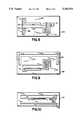
- FIGS. 3a, 3b and 3care diagrams of a dipole antenna with a quarter wave feedline progressively collapsed toward one dipole.
- FIGS. 4-10are diagrams of antennas in accordance with various preferred embodiments of the present invention.
- FIGS. 1-10 of the drawingsThe preferred embodiments of the present invention will now be described with reference to FIGS. 1-10 of the drawings. Identical elements represented in these various figures are designated with the same reference numerals.
- FIG. 1illustrates a typical dipole antenna 10 comprising separate dipole antenna elements 12 and 14.
- a signal source or sink 16is electrically connected to the inner ends 18 and 20 of the dipole elements 12 and 14, respectively, for supplying a signal to, or receiving a signal from the antenna 10.
- FIG. 2shows how the dipole elements may be supplied via a quarter wave transmission line 22 formed by parallel conductive bars 24 and 26 spaced apart by a gap width G and having a length ⁇ /4, where ⁇ is the electrical wavelength at the frequency of operation of the antenna.
- ⁇is the electrical wavelength at the frequency of operation of the antenna.
- the significant variables in the design of an RF transmission lineare the length of the line, the gap width and the dielectric found in the gap.
- FIGS. 3a, 3b and 3cillustrate how the quarter wave- transmission line may be collapsed into one dipole element so that the antenna may be electrically connected to a signal source or sink arranged at one end.
- the transmission linemay be folded toward one (the lefthand) dipole element; as shown in FIG. 3c, the feed line and the lefthand dipole element may be collapsed into a single bar. If the dipole element is the same length as the transmission line ( ⁇ /4, as indicated above), the apparent signal source or sink is at the center of the antenna.
- the antenna shown in FIG. 3cthus comprises planar, conductive antenna elements 14 and 24, hereinafter called “second” and “third” elements, respectively.
- the third elementhas a linear portion 24 extending from one end 30 toward its opposite end.
- the antennaincludes a planar, conductive linear coupling element 26, hereinafter called the "first" element, which extends adjacent to, and in parallel with, the linear portion 24 of the third element.
- the first elementhas one end 34 arranged adjacent to the end 30 of the third element and an opposite end 36 located adjacent to the opposite end 37 of the third element.
- the signal source or sink 16is electrically connected between the end 30 of the third element and the end 34 of the first element.
- FIG. 4shows how a signal source or sink may be inductively coupled to an end fed dipole antenna according to the present invention.
- the signal source/sink 16is electrically connected to an inductive loop 38 which, in turn, is inductively coupled to a partial loop 40 connected between the ends 30 and 34 of the antenna.
- FIG. 5illustrates an antenna with a meander portion 42 extending from a linear portion 24 of the antenna element. This meander portion adjusts the resonant length of the structure.
- FIG. 6shows an antenna which has been enlarged to its maximum dimensions on a card-like, non-conductive substrate 44.
- the resonant length of the structureis adjusted by providing a "tail" 46.
- FIG. 7shows an antenna similar to that of FIG. 5 arranged on a non-conductive substrate 44.
- the antennais inductively coupled to a SAW device 47 which is placed directly over the antenna's inductive loop 40.
- the SAW device 47incorporates a complementary inductive loop for coupling a signal to and from the antenna.
- FIG. 8shows still another antenna configuration, which is presently the best mode for practicing the invention.
- This antennais similar to that of FIGS. 5 and 7 but includes an additional planar, conductive, meander element 48, disposed on the substrate surface, having 2 ends 50 and 52, respectively.
- the end 50is electrically coupled to the end 30 of the antenna.
- This meander elementserves to increase the inductance of the antenna, thereby tuning the antenna to the inductively coupled source or sink.
- FIGS. 9 and 10show additional antenna structures according to the present invention which include reflectors 54 and 56, respectively. These reflectors improve the isolation of the antenna from other reflecting elements in the vicinity.
- the present inventioncontemplates a planar (flat) antenna incorporating a transmission line that permits direct electrical connection (or inductive coupling) to one end of the antenna.
- the transmission lineis formed of two legs: a linear portion of one dipole element itself and a separate, linear coupling element. This transmission line operates to contain a non-radiating field within the interior of the antenna (between the two legs) while permitting radiation to occur on the outside of the antenna.
- the antennais driven from one end, the antenna operates as if the signal source or sink were connected at its center.
Landscapes
- Engineering & Computer Science (AREA)
- Artificial Intelligence (AREA)
- Computer Vision & Pattern Recognition (AREA)
- Physics & Mathematics (AREA)
- General Physics & Mathematics (AREA)
- Theoretical Computer Science (AREA)
- Variable-Direction Aerials And Aerial Arrays (AREA)
- Details Of Aerials (AREA)
- Aerials With Secondary Devices (AREA)
Abstract
Description
This application is a continuation of application Ser. No. 434,233, filed Nov. 13, 1989, now abandoned.
The present invention relates to a flat (planar) antenna of the dipole type which is arranged to be supplied with an electrical signal, and/or to produce an electrical signal at one end.
An antenna of the type to which the present invention relates may be contained in a transponder of a "passive interrogator label system".
A "passive interrogator label system system", so-called, is a radar system utilizing transponders which are capable of receiving an interrogating first signal, processing this signal and transmitting a second signal in reply that is derived from the first signal and contains encoded information. Because the encoded information normally includes an identification code that is unique to each transponder, and because the transponders of such a system are relatively light weight and small and may be easily attached to other objects to be identified, these transponders are sometimes referred to as "labels". Furthermore, the transponders, which may be implemented by SAW devices, carry no self-contained power source, such as a battery, that must be periodically replaced. Consequently, these transponders are denominated as being "passive"; hence the name "passive interrogator label system".
Passive interrogator label systems of the type to which the present invention relates are disclosed, for example, in the following U.S. patents:
U.S. Pat. No. 4,737,789 of Paul A. Nysen for "Inductive Antenna Coupling for a Surface Acoustic Wave Transponder";
U.S. Pat. No. 4,703,327 of Anthony J. Rossetti and Paul A. Nysen for "Interrogator/Receiver System for Use with a Remote Transponder"; and
U.S. Pat. No. 4,737,790 of Halvor Skeie and Donald Armstrong for "Passive Interrogator Label System with a Surface Acoustic Wave Transponder Operating at its Third Harmonic and Having Increased Bandwidth."
In general, a passive interrogator label system includes an "interrogator" for transmitting a first radio frequency signal; at least one passive transponder which receives this first signal, processes it, and sends back a second radio frequency signal containing encoded information; and a receiver, normally located next to the interrogator, for receiving the second signal and decoding the transponder encoded information.
The passive transponder, as disclosed in these patents, comprises a SAW device and a dipole antenna, which is either electrically or inductively coupled to the SAW transducers on the SAW device. The dipole antenna may be formed either by printing conductive ink (e.g. silver ink) on a substrate in the prescribed antenna pattern, or by stamping a metal foil into the size and shape of the antenna pattern, and bonding this foil by heat and pressure to the substrate (e.g. a polyethyline coated Mylar sheet). The antenna with its substrate is therefore relatively flat and thin and, depending upon the radio frequency of operation, is relatively modest in its lateral dimensions.
For example, the antenna characteristics required for this application, operating at a frequency of approximately 915 MHz., determine that the antenna be physically approximately one inch wide and three inches long. The SAW device, to which the antenna is coupled, is also placed on the substrate to form the complete assembly or "label".
Whereas the dipole antenna, with the SAW device mounted between the dipoles, is satisfactory for most ID tag applications, it would be advantageous, in some applications, to locate the SAW device at one end of the antenna. Such arrangement would simplify packaging the SAW device--antenna combination (label) and would reduce the effect on the label of an adjacent physical body.
It is an object of the present invention, therefore, to provide a planar antenna of the dipole type which receives an electrical signal from, and feeds an electrical signal to, electrical terminals at one end of the antenna.
It is a further object of the present invention to provide a planar, end fed antenna which may be inductively coupled to a SAW device or other signal processing element.
These objects, as well as other objects which will become apparent from the discussion that follows, are achieved in accordance with the present invention, by providing (1) a first quarter wavelength element having a first end and an opposite second end; and (2) a second quarter wavelength element having a third end and an opposite fourth end. The first end, second end, third end and fourth end, respectively, of the first and second elements are arranged on a common, substantially straight line with the second and third ends adjacent to each other. In addition, a quarter wavelength third element is positioned adjacent to the first element. The third element has a fifth end and an opposite sixth end; the fifth end is arranged adjacent to the first end of the first element and the sixth end is arranged adjacent to, and is physically connected with the third end of the second element.
With this antenna, a SAW device, or other signal source or sink may be electrically coupled between the first end of the first element and the fifth end of the third element to provide an electrical signal to and/or receive an electrical signal from the antenna.
In a preferred embodiment of the present invention, this source or sink comprises an inductive loop connected between the aformentioned first end and the fifth end for transmitting and/or receiving an inductively coupled input/output signal to and/or from the antenna.
For a full understanding of the present invention, reference should now be made to the following detailed description of the preferred embodiments thereof, taken in conjunction with the accompanying drawings.
FIG. 1 is a representational diagram of a dipole antenna.
FIG. 2 is a representational diagram of a dipole antenna with a quarter wave feedline.
FIGS. 3a, 3b and 3c are diagrams of a dipole antenna with a quarter wave feedline progressively collapsed toward one dipole.
FIGS. 4-10 are diagrams of antennas in accordance with various preferred embodiments of the present invention.
The preferred embodiments of the present invention will now be described with reference to FIGS. 1-10 of the drawings. Identical elements represented in these various figures are designated with the same reference numerals.
FIG. 1 illustrates atypical dipole antenna 10 comprising separatedipole antenna elements sink 16 is electrically connected to theinner ends dipole elements antenna 10.
FIG. 2 shows how the dipole elements may be supplied via a quarterwave transmission line 22 formed by parallelconductive bars
FIGS. 3a, 3b and 3c illustrate how the quarter wave- transmission line may be collapsed into one dipole element so that the antenna may be electrically connected to a signal source or sink arranged at one end.
As shown in FIGS. 3a and 3b, the transmission line may be folded toward one (the lefthand) dipole element; as shown in FIG. 3c, the feed line and the lefthand dipole element may be collapsed into a single bar. If the dipole element is the same length as the transmission line (λ/4, as indicated above), the apparent signal source or sink is at the center of the antenna.
The antenna shown in FIG. 3c thus comprises planar,conductive antenna elements linear portion 24 extending from oneend 30 toward its opposite end. In addition, the antenna includes a planar, conductivelinear coupling element 26, hereinafter called the "first" element, which extends adjacent to, and in parallel with, thelinear portion 24 of the third element. The first element has oneend 34 arranged adjacent to theend 30 of the third element and anopposite end 36 located adjacent to theopposite end 37 of the third element. The signal source orsink 16 is electrically connected between theend 30 of the third element and theend 34 of the first element.
FIG. 4 shows how a signal source or sink may be inductively coupled to an end fed dipole antenna according to the present invention. As is there shown, the signal source/sink 16 is electrically connected to an inductive loop 38 which, in turn, is inductively coupled to apartial loop 40 connected between theends
FIG. 5 illustrates an antenna with ameander portion 42 extending from alinear portion 24 of the antenna element. This meander portion adjusts the resonant length of the structure.
FIG. 6 shows an antenna which has been enlarged to its maximum dimensions on a card-like, non-conductivesubstrate 44. The resonant length of the structure is adjusted by providing a "tail" 46.
FIG. 7 shows an antenna similar to that of FIG. 5 arranged on anon-conductive substrate 44. The antenna is inductively coupled to aSAW device 47 which is placed directly over the antenna'sinductive loop 40. TheSAW device 47 incorporates a complementary inductive loop for coupling a signal to and from the antenna.
FIG. 8 shows still another antenna configuration, which is presently the best mode for practicing the invention. This antenna is similar to that of FIGS. 5 and 7 but includes an additional planar, conductive,meander element 48, disposed on the substrate surface, having 2 ends 50 and 52, respectively. Theend 50 is electrically coupled to theend 30 of the antenna. This meander element serves to increase the inductance of the antenna, thereby tuning the antenna to the inductively coupled source or sink.
FIGS. 9 and 10 show additional antenna structures according to the present invention which includereflectors
In summary, the present invention contemplates a planar (flat) antenna incorporating a transmission line that permits direct electrical connection (or inductive coupling) to one end of the antenna. The transmission line is formed of two legs: a linear portion of one dipole element itself and a separate, linear coupling element. This transmission line operates to contain a non-radiating field within the interior of the antenna (between the two legs) while permitting radiation to occur on the outside of the antenna. Although the antenna is driven from one end, the antenna operates as if the signal source or sink were connected at its center.
There has thus been shown and described a novel planar antenna which fulfills all the objects and advantages sought therefor. Many changes, modifications variations and other uses and applications of the subject invention will, however, become apparent to those skilled in the art after considering this specification and the accompanying drawings which disclose the preferred embodiments thereof. All such changes, modifications, variations and other uses and applications which do not depart from the spirit and scope of the invention are deemed to be covered by the invention which is limited only by the claims which follow.
Claims (7)
1. An end fed dipole antenna for radiating electromagnetic waves of wavelength λ, said antenna comprising in combination:
(a) a first element having an effective radiating length substantially equal to λ/4, said first element having a first end and an opposite second end;
(b) a second element having an effective radiating length substantially equal to λ/4, said second element having a third end and an opposite fourth end, said first end, second end, third end and fourth end, respectively, being arranged on a common, substantially straight line with said second and third ends being adjacent to each other;
(c) a third element having an effective transmission length substantially equal to λ/4, said third element having a fifth end and an opposite sixth end and being arranged adjacent to said first element with said fifth end adjacent to said first end of said first element and said sixth end both adjacent to and physically connected with said third end of said second element; and
(d) energy providing means coupled to said first end of said first element and said fifth end of said third element for providing electrical energy to, and/or receiving electrical energy from said antenna.
2. The antenna defined in claim 1, wherein said second element includes a meander portion.
3. The antenna defined in claim 1, wherein energy providing means (d) energy providing includes an inductive loop connected between said first end and said fifth end for receiving and/or transmitting an inductively coupled input/output signal.
4. The antenna defined in claim 1, further comprising a reflector element arranged adjacent to said first and second elements and substantially in parallel with said straight line, said reflector element having a substantially linear reflective portion extending from a point adjacent said first end to a point adjacent said fourth end of said first and second elements, respectively.
5. The antenna defined in claim 4, wherein said reflector element is disposed on a common substrate surface with said first and second elements.
6. The antenna defined in claim 1, wherein said first, second and third elements are disposed on a common planar substrate surface, and wherein said antenna comprises a planar conductive element disposed on said substrate surface and having a seventh end and an opposite eighth end, said seventh end being electrically coupled to at least one of said first and fifth ends.
7. The antenna defined in claim 3, wherein said first, second and third elements are disposed on a common planar substrate surface, and wherein said inductive loop includes a partial inductive loop connected between said first end and said fifth end for transmitting or receiving said input/output signal, said partial inductive loop being co-planar with said first, second and third elements.
Priority Applications (1)
| Application Number | Priority Date | Filing Date | Title |
|---|---|---|---|
| US07/803,712US5182570A (en) | 1989-11-13 | 1991-12-04 | End fed flat antenna |
Applications Claiming Priority (2)
| Application Number | Priority Date | Filing Date | Title |
|---|---|---|---|
| US43423389A | 1989-11-13 | 1989-11-13 | |
| US07/803,712US5182570A (en) | 1989-11-13 | 1991-12-04 | End fed flat antenna |
Related Parent Applications (1)
| Application Number | Title | Priority Date | Filing Date |
|---|---|---|---|
| US43423389AContinuation | 1989-11-13 | 1989-11-13 |
Publications (1)
| Publication Number | Publication Date |
|---|---|
| US5182570Atrue US5182570A (en) | 1993-01-26 |
Family
ID=27030111
Family Applications (1)
| Application Number | Title | Priority Date | Filing Date |
|---|---|---|---|
| US07/803,712Expired - LifetimeUS5182570A (en) | 1989-11-13 | 1991-12-04 | End fed flat antenna |
Country Status (1)
| Country | Link |
|---|---|
| US (1) | US5182570A (en) |
Cited By (61)
| Publication number | Priority date | Publication date | Assignee | Title |
|---|---|---|---|---|
| US5598174A (en)* | 1995-08-12 | 1997-01-28 | Lucent Technologies, Inc. | Printed sleeve antenna |
| US5654693A (en)* | 1996-04-10 | 1997-08-05 | X-Cyte, Inc. | Layered structure for a transponder tag |
| US5689262A (en)* | 1994-07-11 | 1997-11-18 | Mcdonnell Douglas Corporation | Electronic baffle and baffle controlled microwave devices |
| US5697583A (en)* | 1996-09-13 | 1997-12-16 | Dorne & Margolin, Inc. | Radio frequency coupler for communication between adjacent railway cars |
| US5986382A (en) | 1997-08-18 | 1999-11-16 | X-Cyte, Inc. | Surface acoustic wave transponder configuration |
| US6023243A (en)* | 1997-10-14 | 2000-02-08 | Mti Technology & Engineering (1993) Ltd. | Flat plate antenna arrays |
| WO2000016284A1 (en)* | 1998-09-11 | 2000-03-23 | Key-Trak, Inc. | Tamper detection and prevention for an object control and tracking system |
| WO2000016280A1 (en)* | 1998-09-11 | 2000-03-23 | Key-Trak, Inc. | Object tracking system with non-contact object detection and identification |
| WO2000023994A1 (en)* | 1998-10-16 | 2000-04-27 | Intermec Ip Corp. | Smart optical storage media |
| US6060815A (en) | 1997-08-18 | 2000-05-09 | X-Cyte, Inc. | Frequency mixing passive transponder |
| US6107910A (en) | 1996-11-29 | 2000-08-22 | X-Cyte, Inc. | Dual mode transmitter/receiver and decoder for RF transponder tags |
| US6114971A (en) | 1997-08-18 | 2000-09-05 | X-Cyte, Inc. | Frequency hopping spread spectrum passive acoustic wave identification device |
| US6195005B1 (en) | 1998-09-11 | 2001-02-27 | Key-Trak, Inc. | Object carriers for an object control and tracking system |
| US6208062B1 (en) | 1997-08-18 | 2001-03-27 | X-Cyte, Inc. | Surface acoustic wave transponder configuration |
| US6232876B1 (en) | 1998-09-11 | 2001-05-15 | Key-Trak, Inc. | Mobile object tracking system |
| US6259991B1 (en) | 1999-02-10 | 2001-07-10 | X-Cyte Inc. | Environmental location system |
| US6285342B1 (en)* | 1998-10-30 | 2001-09-04 | Intermec Ip Corp. | Radio frequency tag with miniaturized resonant antenna |
| US6285323B1 (en) | 1997-10-14 | 2001-09-04 | Mti Technology & Engineering (1993) Ltd. | Flat plate antenna arrays |
| US6317044B1 (en) | 1996-09-05 | 2001-11-13 | Key-Track, Inc. | Inventoriable object control and tracking system |
| US6346922B1 (en)* | 1999-02-01 | 2002-02-12 | Supersensor (Proprietary) Limited | Hybrid antenna arrangement for use with electronic identification systems |
| US20020075152A1 (en)* | 2000-12-15 | 2002-06-20 | Paul Nysen | Apparatus and method for locating a tagged item |
| US6427913B1 (en) | 1998-09-11 | 2002-08-06 | Key-Trak, Inc. | Object control and tracking system with zonal transition detection |
| US20030184437A1 (en)* | 1998-09-11 | 2003-10-02 | Maloney William C. | Object carriers and lighted tags for an object control and tracking system |
| US6633226B1 (en) | 1997-08-18 | 2003-10-14 | X-Cyte, Inc. | Frequency hopping spread spectrum passive acoustic wave identification device |
| US20030218667A1 (en)* | 2002-02-19 | 2003-11-27 | Williams Richard A. | Multiple resolution helical imaging system and method |
| US6707381B1 (en) | 2001-06-26 | 2004-03-16 | Key-Trak, Inc. | Object tracking method and system with object identification and verification |
| US20040104858A1 (en)* | 2001-12-15 | 2004-06-03 | Markus Pfletschinger | Wide band slot cavity antenna |
| US6775616B1 (en) | 1999-02-10 | 2004-08-10 | X-Cyte, Inc. | Environmental location system |
| US20040178912A1 (en)* | 1999-09-02 | 2004-09-16 | Smith Freddie W. | Remote communication devices, radio frequency identification devices, wireless communication systems, wireless communication methods, radio frequency identification device communication methods, and methods of forming a remote communication device |
| US20040229560A1 (en)* | 2002-10-10 | 2004-11-18 | Maloney William C. | Methods of tracking and verifying human assets |
| US20050134506A1 (en)* | 2003-12-23 | 2005-06-23 | 3M Innovative Properties Company | Ultra high frequency radio frequency identification tag |
| US20050198811A1 (en)* | 2004-03-12 | 2005-09-15 | A K Stamping Co. Inc. | Manufacture of RFID tags and intermediate products therefor |
| US20050212707A1 (en)* | 2004-03-23 | 2005-09-29 | Egbert William C | Radio frequency identification tags with compensating elements |
| US20070018904A1 (en)* | 1998-02-04 | 2007-01-25 | Smith Freddie W | Communication devices, communication systems and methods of communicating |
| EP1689031A3 (en)* | 2000-10-03 | 2007-05-23 | Mineral Lassen LLC | Multi-band wireless communication device |
| US20070195002A1 (en)* | 2006-02-22 | 2007-08-23 | Kin-Lu Wong | Digital-Television Receiving Antenna |
| JP2007281784A (en)* | 2006-04-05 | 2007-10-25 | Ykc:Kk | Self-complementary antenna |
| US20070273473A1 (en)* | 1997-08-14 | 2007-11-29 | Bates Benjamin G | Wireless communications devices, wireless communications systems, and methods of performing wireless communications with a portable device |
| US20080055045A1 (en)* | 2006-08-31 | 2008-03-06 | 3M Innovative Properties Company | Rfid tag including a three-dimensional antenna |
| US7376234B1 (en) | 2001-05-14 | 2008-05-20 | Hand Held Products, Inc. | Portable keying device and method |
| US20080122699A1 (en)* | 2006-06-15 | 2008-05-29 | Industrial Technology Research Institute | Broadband antenna |
| US20090015407A1 (en)* | 2007-07-13 | 2009-01-15 | Micron Technology, Inc. | Rifid tags and methods of designing rfid tags |
| US20090027168A1 (en)* | 2007-07-26 | 2009-01-29 | Micron Technology, Inc. | Methods and systems of rfid tags using rfid circuits and antennas having unmatched frequency ranges |
| US20090085746A1 (en)* | 2007-09-27 | 2009-04-02 | 3M Innovative Properties Company | Signal line structure for a radio-frequency identification system |
| US20090085750A1 (en)* | 2007-09-27 | 2009-04-02 | 3M Innovative Properties Company | Extended RFID tag |
| US20090096696A1 (en)* | 2007-10-11 | 2009-04-16 | Joyce Jr Terrence H | Rfid tag with a modified dipole antenna |
| US20090207027A1 (en)* | 2008-02-14 | 2009-08-20 | Banerjee Swagata R | Radio frequency identification (rfid) tag including a three-dimensional loop antenna |
| US20090273449A1 (en)* | 2008-05-05 | 2009-11-05 | Keystone Technology Solutions, Llc | RFID Interrogator With Adjustable Signal Characteristics |
| US20090278688A1 (en)* | 2008-05-08 | 2009-11-12 | Keystone Technology Solutions, Llc | RFID Devices Using RFID Circuits and Antennas Having Unmatched Frequency Ranges |
| US20090289771A1 (en)* | 2008-05-20 | 2009-11-26 | Keystone Technology Solutions, Llc | RFID Device Using Single Antenna For Multiple Resonant Frequency Ranges |
| CN101110495B (en)* | 2006-07-17 | 2011-10-26 | 光宝科技股份有限公司 | A Broadband Flat Digital TV Receiving Antenna |
| US20120001818A1 (en)* | 2009-04-13 | 2012-01-05 | Laird Technologies, Inc. | Multi-band dipole antennas |
| CN101110496B (en)* | 2006-07-19 | 2012-07-04 | 财团法人工业技术研究院 | broadband antenna |
| US8311834B1 (en) | 1999-06-10 | 2012-11-13 | Gazdzinski Robert F | Computerized information selection and download apparatus and methods |
| US8371503B2 (en) | 2003-12-17 | 2013-02-12 | Robert F. Gazdzinski | Portable computerized wireless payment apparatus and methods |
| EP2359436A4 (en)* | 2008-11-19 | 2013-04-17 | Tyco Electronics Services Gmbh | Tunable metamaterial antenna structures |
| US8812368B1 (en) | 1999-03-01 | 2014-08-19 | West View Research, Llc | Computerized information collection and processing apparatus |
| TWI572097B (en)* | 2015-07-14 | 2017-02-21 | 智易科技股份有限公司 | Dual-band antenna |
| US9861296B2 (en) | 1999-03-01 | 2018-01-09 | West View Research, Llc | Ingestible probe with agent delivery |
| WO2020075732A1 (en)* | 2018-10-10 | 2020-04-16 | 株式会社フェニックスソリューション | Rf tag for embedding in tire, and rf-tagged tire |
| JP2021002254A (en)* | 2019-06-24 | 2021-01-07 | 株式会社梅垣ラベルサービス | Rf tag label and rf tag label attached rubber-based product |
Citations (13)
| Publication number | Priority date | Publication date | Assignee | Title |
|---|---|---|---|---|
| US3025524A (en)* | 1959-05-06 | 1962-03-13 | Charles H Thies | Calibrated thin metal lamina antenna |
| US3689929A (en)* | 1970-11-23 | 1972-09-05 | Howard B Moody | Antenna structure |
| US3845490A (en)* | 1973-05-03 | 1974-10-29 | Gen Electric | Stripline slotted balun dipole antenna |
| US4138681A (en)* | 1977-08-29 | 1979-02-06 | Motorola, Inc. | Portable radio antenna |
| US4259673A (en)* | 1979-06-05 | 1981-03-31 | Harold Guretzky | Stub matched antenna and method of feeding same |
| US4400702A (en)* | 1980-05-13 | 1983-08-23 | Hiroki Tanaka | Shortened antenna having coaxial lines as its elements |
| US4642640A (en)* | 1983-04-25 | 1987-02-10 | Sensormatic Electronics Corporation | Signal receptor-reradiator and surveillance tag using the same |
| US4703327A (en)* | 1985-10-31 | 1987-10-27 | X-Cyte, Inc. | Interrogator/receiver system for use with a remote transponder |
| US4737789A (en)* | 1986-12-02 | 1988-04-12 | X Cyte, Inc. | Inductive antenna coupling for a surface acoustic wave transponder |
| US4737790A (en)* | 1986-03-03 | 1988-04-12 | X-Cyte, Inc. | Passive interrogator label system with a surface acoustic wave transponder operating at its third harmonic and having increased bandwidth |
| US4800392A (en)* | 1987-01-08 | 1989-01-24 | Motorola, Inc. | Integral laminar antenna and radio housing |
| US4951057A (en)* | 1989-11-13 | 1990-08-21 | X-Cyte, Inc. | Inductive input/output coupling for a surface acoustic wave device |
| US5027107A (en)* | 1988-07-06 | 1991-06-25 | Hitachi, Ltd. | Frequency sensor |
- 1991
- 1991-12-04USUS07/803,712patent/US5182570A/ennot_activeExpired - Lifetime
Patent Citations (13)
| Publication number | Priority date | Publication date | Assignee | Title |
|---|---|---|---|---|
| US3025524A (en)* | 1959-05-06 | 1962-03-13 | Charles H Thies | Calibrated thin metal lamina antenna |
| US3689929A (en)* | 1970-11-23 | 1972-09-05 | Howard B Moody | Antenna structure |
| US3845490A (en)* | 1973-05-03 | 1974-10-29 | Gen Electric | Stripline slotted balun dipole antenna |
| US4138681A (en)* | 1977-08-29 | 1979-02-06 | Motorola, Inc. | Portable radio antenna |
| US4259673A (en)* | 1979-06-05 | 1981-03-31 | Harold Guretzky | Stub matched antenna and method of feeding same |
| US4400702A (en)* | 1980-05-13 | 1983-08-23 | Hiroki Tanaka | Shortened antenna having coaxial lines as its elements |
| US4642640A (en)* | 1983-04-25 | 1987-02-10 | Sensormatic Electronics Corporation | Signal receptor-reradiator and surveillance tag using the same |
| US4703327A (en)* | 1985-10-31 | 1987-10-27 | X-Cyte, Inc. | Interrogator/receiver system for use with a remote transponder |
| US4737790A (en)* | 1986-03-03 | 1988-04-12 | X-Cyte, Inc. | Passive interrogator label system with a surface acoustic wave transponder operating at its third harmonic and having increased bandwidth |
| US4737789A (en)* | 1986-12-02 | 1988-04-12 | X Cyte, Inc. | Inductive antenna coupling for a surface acoustic wave transponder |
| US4800392A (en)* | 1987-01-08 | 1989-01-24 | Motorola, Inc. | Integral laminar antenna and radio housing |
| US5027107A (en)* | 1988-07-06 | 1991-06-25 | Hitachi, Ltd. | Frequency sensor |
| US4951057A (en)* | 1989-11-13 | 1990-08-21 | X-Cyte, Inc. | Inductive input/output coupling for a surface acoustic wave device |
Non-Patent Citations (3)
| Title |
|---|
| F. C. Judd, Two metre Antenna Handbook, Omnidirectional Antennas (Chapter 2), pp. 25 33, 1980.* |
| F. C. Judd, Two-metre Antenna Handbook, Omnidirectional Antennas (Chapter 2), pp. 25-33, 1980. |
| UK Patent Application, Hill et al. GB 2142475 Wide Beam Microwave Antenna Jan. 1985.* |
Cited By (171)
| Publication number | Priority date | Publication date | Assignee | Title |
|---|---|---|---|---|
| US5689262A (en)* | 1994-07-11 | 1997-11-18 | Mcdonnell Douglas Corporation | Electronic baffle and baffle controlled microwave devices |
| US5847672A (en)* | 1994-07-11 | 1998-12-08 | Mcdonnell Douglas Corporation | Electronic baffle and baffle controlled microwave devices |
| US5598174A (en)* | 1995-08-12 | 1997-01-28 | Lucent Technologies, Inc. | Printed sleeve antenna |
| US6707380B2 (en) | 1995-09-08 | 2004-03-16 | Key-Trak, Inc. | Inventoriable-object control and tracking system |
| US7342494B2 (en) | 1995-09-08 | 2008-03-11 | Key Control Holding, Inc. | Inventoriable-object control and tracking system |
| US5654693A (en)* | 1996-04-10 | 1997-08-05 | X-Cyte, Inc. | Layered structure for a transponder tag |
| US6317044B1 (en) | 1996-09-05 | 2001-11-13 | Key-Track, Inc. | Inventoriable object control and tracking system |
| US5697583A (en)* | 1996-09-13 | 1997-12-16 | Dorne & Margolin, Inc. | Radio frequency coupler for communication between adjacent railway cars |
| US7741956B1 (en) | 1996-11-29 | 2010-06-22 | X-Cyte, Inc. | Dual mode transmitter-receiver and decoder for RF transponder tags |
| US6531957B1 (en)* | 1996-11-29 | 2003-03-11 | X-Cyte, Inc. | Dual mode transmitter-receiver and decoder for RF transponder tags |
| US6950009B1 (en) | 1996-11-29 | 2005-09-27 | X-Cyte, Inc. | Dual mode transmitter/receiver and decoder for RF transponder units |
| US6107910A (en) | 1996-11-29 | 2000-08-22 | X-Cyte, Inc. | Dual mode transmitter/receiver and decoder for RF transponder tags |
| US8130077B2 (en) | 1997-08-14 | 2012-03-06 | Round Rock Research, Llc | Wireless communications devices |
| US20070273473A1 (en)* | 1997-08-14 | 2007-11-29 | Bates Benjamin G | Wireless communications devices, wireless communications systems, and methods of performing wireless communications with a portable device |
| US8232865B2 (en) | 1997-08-14 | 2012-07-31 | Round Rock Research, Llc | Wireless communication devices |
| US20070285208A1 (en)* | 1997-08-14 | 2007-12-13 | Keystone Technology Solutions, Llc | Secure Cargo Transportation System |
| US8633800B2 (en) | 1997-08-14 | 2014-01-21 | Round Rock Research, Llc | Methods of configuring and using a wireless communications device |
| US7777608B2 (en) | 1997-08-14 | 2010-08-17 | Round Rock Research, Llc | Secure cargo transportation system |
| US7920047B2 (en) | 1997-08-14 | 2011-04-05 | Round Rock Research, Llc | Wireless communications devices, wireless communications systems, and methods of performing wireless communications with a portable device |
| US20070285207A1 (en)* | 1997-08-14 | 2007-12-13 | Keystone Technology Solutions, Llc | Secure Cargo Transportation System |
| US20070285213A1 (en)* | 1997-08-14 | 2007-12-13 | Keystone Technology Solutions, Llc | Secure Cargo Transportation System |
| US7023323B1 (en) | 1997-08-18 | 2006-04-04 | X-Cyte, Inc. | Frequency hopping spread spectrum passive acoustic wave identification device |
| US6208062B1 (en) | 1997-08-18 | 2001-03-27 | X-Cyte, Inc. | Surface acoustic wave transponder configuration |
| US6114971A (en) | 1997-08-18 | 2000-09-05 | X-Cyte, Inc. | Frequency hopping spread spectrum passive acoustic wave identification device |
| US6060815A (en) | 1997-08-18 | 2000-05-09 | X-Cyte, Inc. | Frequency mixing passive transponder |
| US7132778B1 (en) | 1997-08-18 | 2006-11-07 | X-Cyte, Inc. | Surface acoustic wave modulator |
| US5986382A (en) | 1997-08-18 | 1999-11-16 | X-Cyte, Inc. | Surface acoustic wave transponder configuration |
| US6611224B1 (en)* | 1997-08-18 | 2003-08-26 | X-Cyte, Inc. | Backscatter transponder interrogation device |
| US6633226B1 (en) | 1997-08-18 | 2003-10-14 | X-Cyte, Inc. | Frequency hopping spread spectrum passive acoustic wave identification device |
| US6285323B1 (en) | 1997-10-14 | 2001-09-04 | Mti Technology & Engineering (1993) Ltd. | Flat plate antenna arrays |
| EP0910134A3 (en)* | 1997-10-14 | 2001-02-28 | MTI Technology & Engineering (1993) Ltd. | Flat plate antenna arrays |
| US6023243A (en)* | 1997-10-14 | 2000-02-08 | Mti Technology & Engineering (1993) Ltd. | Flat plate antenna arrays |
| US20070018904A1 (en)* | 1998-02-04 | 2007-01-25 | Smith Freddie W | Communication devices, communication systems and methods of communicating |
| US7898389B2 (en) | 1998-02-04 | 2011-03-01 | Round Rock Research, Llc | Radio frequency identification (RFID) tags and methods of communicating between a radio frequency identification (RFID) tag and an interrogator |
| US6232876B1 (en) | 1998-09-11 | 2001-05-15 | Key-Trak, Inc. | Mobile object tracking system |
| US20050099305A1 (en)* | 1998-09-11 | 2005-05-12 | Maloney William C. | Object carriers for an object control and tracking system |
| US20040021570A1 (en)* | 1998-09-11 | 2004-02-05 | Key-Trak, Inc. | Mobile object tracking system |
| US6693538B2 (en) | 1998-09-11 | 2004-02-17 | Key-Trak, Inc. | Object carriers for an object control and tracking system |
| US20030184437A1 (en)* | 1998-09-11 | 2003-10-02 | Maloney William C. | Object carriers and lighted tags for an object control and tracking system |
| US6501379B2 (en) | 1998-09-11 | 2002-12-31 | Key-Trak, Inc. | Object carriers for an object control and tracking system |
| US6727817B2 (en) | 1998-09-11 | 2004-04-27 | Key-Trak, Inc. | Tamper detection and prevention for an object control and tracking system |
| US20040095241A1 (en)* | 1998-09-11 | 2004-05-20 | Key-Trak, Inc. | Object tracking system with non-contact object detection and identification |
| US6427913B1 (en) | 1998-09-11 | 2002-08-06 | Key-Trak, Inc. | Object control and tracking system with zonal transition detection |
| US20040113785A1 (en)* | 1998-09-11 | 2004-06-17 | Key-Trak, Inc. | Object carriers for an object control and tracking system |
| US6424260B2 (en) | 1998-09-11 | 2002-07-23 | Key-Trak, Inc. | Mobile object tracking system |
| WO2000016284A1 (en)* | 1998-09-11 | 2000-03-23 | Key-Trak, Inc. | Tamper detection and prevention for an object control and tracking system |
| US20040172554A1 (en)* | 1998-09-11 | 2004-09-02 | Key-Trak, Inc. | Tamper detection and prevention for an object control and tracking system |
| US6407665B2 (en) | 1998-09-11 | 2002-06-18 | Key-Trak, Inc. | Object tracking system with non-contact object detection and identification |
| US6392543B2 (en) | 1998-09-11 | 2002-05-21 | Key-Trak, Inc. | Mobile object tracking system |
| US20050040232A1 (en)* | 1998-09-11 | 2005-02-24 | Key-Trak, Inc. | Object control and tracking system with zonal transition detection |
| US6891473B2 (en) | 1998-09-11 | 2005-05-10 | Key-Trak, Inc. | Object carriers and lighted tags for an object control and tracking system |
| US20030201321A1 (en)* | 1998-09-11 | 2003-10-30 | Key-Trak, Inc. | Object control and tracking system with zonal transition detection |
| US7109864B2 (en) | 1998-09-11 | 2006-09-19 | Key Control Holding, Inc. | Object carriers and lighted tags for an object control and tracking system |
| US20050156739A1 (en)* | 1998-09-11 | 2005-07-21 | Maloney William C. | Object tracking system with non-contact object detection and identification |
| US7046145B2 (en) | 1998-09-11 | 2006-05-16 | Key Control Holding, Inc. | Object carriers for an object control and tracking system |
| US20050156740A1 (en)* | 1998-09-11 | 2005-07-21 | Maloney William C. | Mobile object tracking system |
| US20050179547A1 (en)* | 1998-09-11 | 2005-08-18 | Maloney William C. | Object carriers and lighted tags for an object control and tracking system |
| US6262664B1 (en) | 1998-09-11 | 2001-07-17 | Key-Trak, Inc. | Tamper detection prevention for an object control and tracking system |
| WO2000016280A1 (en)* | 1998-09-11 | 2000-03-23 | Key-Trak, Inc. | Object tracking system with non-contact object detection and identification |
| US6204764B1 (en) | 1998-09-11 | 2001-03-20 | Key-Trak, Inc. | Object tracking system with non-contact object detection and identification |
| US6958698B2 (en) | 1998-09-11 | 2005-10-25 | Key-Trak, Inc. | Tamper detection and prevention for an object control and tracking system |
| US6195005B1 (en) | 1998-09-11 | 2001-02-27 | Key-Trak, Inc. | Object carriers for an object control and tracking system |
| US7202785B2 (en) | 1998-09-11 | 2007-04-10 | Key Control Holding, Inc. | Mobile object tracking system |
| US7005984B2 (en) | 1998-09-11 | 2006-02-28 | Key-Trak, Inc. | Object carriers for an object control and tracking system |
| US7250865B2 (en) | 1998-09-11 | 2007-07-31 | Key Control Holding, Inc. | Object tracking system with non-contact object detection and identification |
| WO2000023994A1 (en)* | 1998-10-16 | 2000-04-27 | Intermec Ip Corp. | Smart optical storage media |
| US6285342B1 (en)* | 1998-10-30 | 2001-09-04 | Intermec Ip Corp. | Radio frequency tag with miniaturized resonant antenna |
| US6346922B1 (en)* | 1999-02-01 | 2002-02-12 | Supersensor (Proprietary) Limited | Hybrid antenna arrangement for use with electronic identification systems |
| US6259991B1 (en) | 1999-02-10 | 2001-07-10 | X-Cyte Inc. | Environmental location system |
| US6775616B1 (en) | 1999-02-10 | 2004-08-10 | X-Cyte, Inc. | Environmental location system |
| US10028645B2 (en) | 1999-03-01 | 2018-07-24 | West View Research, Llc | Computerized information collection and processing apparatus |
| US9861268B2 (en) | 1999-03-01 | 2018-01-09 | West View Research, Llc | Methods of processing data obtained from medical device |
| US8812368B1 (en) | 1999-03-01 | 2014-08-19 | West View Research, Llc | Computerized information collection and processing apparatus |
| US10973397B2 (en) | 1999-03-01 | 2021-04-13 | West View Research, Llc | Computerized information collection and processing apparatus |
| US10154777B2 (en) | 1999-03-01 | 2018-12-18 | West View Research, Llc | Computerized information collection and processing apparatus and methods |
| US10098568B2 (en) | 1999-03-01 | 2018-10-16 | West View Research, Llc | Computerized apparatus with ingestible probe |
| US10028646B2 (en) | 1999-03-01 | 2018-07-24 | West View Research, Llc | Computerized information collection and processing apparatus |
| US9913575B2 (en) | 1999-03-01 | 2018-03-13 | West View Research, Llc | Methods of processing data obtained from medical device |
| US9861296B2 (en) | 1999-03-01 | 2018-01-09 | West View Research, Llc | Ingestible probe with agent delivery |
| US8676587B1 (en) | 1999-06-10 | 2014-03-18 | West View Research, Llc | Computerized information and display apparatus and methods |
| US9715368B2 (en) | 1999-06-10 | 2017-07-25 | West View Research, Llc | Computerized information and display apparatus with rapid convergence algorithm |
| US9709972B2 (en) | 1999-06-10 | 2017-07-18 | West View Research, Llc | Computerized information and display apparatus with remote environment control |
| US9710225B2 (en) | 1999-06-10 | 2017-07-18 | West View Research, Llc | Computerized information and display apparatus with automatic context determination |
| US8781839B1 (en) | 1999-06-10 | 2014-07-15 | West View Research, Llc | Computerized information and display apparatus |
| US8719038B1 (en) | 1999-06-10 | 2014-05-06 | West View Research, Llc | Computerized information and display apparatus |
| US8311834B1 (en) | 1999-06-10 | 2012-11-13 | Gazdzinski Robert F | Computerized information selection and download apparatus and methods |
| US20040178912A1 (en)* | 1999-09-02 | 2004-09-16 | Smith Freddie W. | Remote communication devices, radio frequency identification devices, wireless communication systems, wireless communication methods, radio frequency identification device communication methods, and methods of forming a remote communication device |
| US7710273B2 (en)* | 1999-09-02 | 2010-05-04 | Round Rock Research, Llc | Remote communication devices, radio frequency identification devices, wireless communication systems, wireless communication methods, radio frequency identification device communication methods, and methods of forming a remote communication device |
| US7969313B2 (en) | 1999-09-02 | 2011-06-28 | Round Rock Research, Llc | Remote communication devices, radio frequency identification devices, wireless communication systems, wireless communication methods, radio frequency identification device communication methods, and methods of forming a remote communication device |
| US20070290807A1 (en)* | 1999-09-02 | 2007-12-20 | Smith Freddie W | Remote Communication Devices, Radio Frequency Identification Devices, Wireless Communication Systems, Wireless Communication Methods, Radio Frequency Identification Device Communication Methods, and Methods of Forming a Remote Communication Device |
| US20110025506A1 (en)* | 1999-09-02 | 2011-02-03 | Round Rock Research, Llc | Remote communication devices, radio frequency identification devices, wireless communication systems, wireless communication methods, radio frequency identification device communication methods, and methods of forming a remote communication device |
| US7786872B2 (en) | 1999-09-02 | 2010-08-31 | Round Rock Research, Llc | Remote communication devices, radio frequency identification devices, wireless communication systems, wireless communication methods, radio frequency identification device communication methods, and methods of forming a remote communication device |
| EP1689031A3 (en)* | 2000-10-03 | 2007-05-23 | Mineral Lassen LLC | Multi-band wireless communication device |
| US6995654B2 (en) | 2000-12-15 | 2006-02-07 | X-Cyte, Inc. | Apparatus and method for locating a tagged item |
| US20020075152A1 (en)* | 2000-12-15 | 2002-06-20 | Paul Nysen | Apparatus and method for locating a tagged item |
| US7376234B1 (en) | 2001-05-14 | 2008-05-20 | Hand Held Products, Inc. | Portable keying device and method |
| US9137009B1 (en) | 2001-05-14 | 2015-09-15 | Hand Held Products, Inc. | Portable keying device and method |
| US7317393B2 (en) | 2001-06-26 | 2008-01-08 | Key Control Holding, Inc. | Object tracking method and system with object identification and verification |
| US6707381B1 (en) | 2001-06-26 | 2004-03-16 | Key-Trak, Inc. | Object tracking method and system with object identification and verification |
| US20040113786A1 (en)* | 2001-06-26 | 2004-06-17 | Key-Trak, Inc. | Object tracking method and system with object identification and verification |
| US7019705B2 (en) | 2001-12-15 | 2006-03-28 | Hirschmann Electronics Gmbh & Co., Kg | Wide band slot cavity antenna |
| US20040104858A1 (en)* | 2001-12-15 | 2004-06-03 | Markus Pfletschinger | Wide band slot cavity antenna |
| US20030218667A1 (en)* | 2002-02-19 | 2003-11-27 | Williams Richard A. | Multiple resolution helical imaging system and method |
| US20040229560A1 (en)* | 2002-10-10 | 2004-11-18 | Maloney William C. | Methods of tracking and verifying human assets |
| US8622286B2 (en) | 2003-12-17 | 2014-01-07 | West View Research, Llc | Portable computerized wireless payment apparatus and methods |
| US8640944B1 (en) | 2003-12-17 | 2014-02-04 | West View Research, Llc | Portable computerized wireless payment apparatus and methods |
| US8613390B2 (en) | 2003-12-17 | 2013-12-24 | West View Research, Llc | Computerized wireless payment methods |
| US10057265B2 (en) | 2003-12-17 | 2018-08-21 | West View Research, Llc | Computerized vehicular apparatus for location-based service provision |
| US11240238B2 (en) | 2003-12-17 | 2022-02-01 | West View Research, Llc | Computerized apparatus and methods for location-based service provision |
| US11870778B2 (en) | 2003-12-17 | 2024-01-09 | West View Research, Llc | Computerized apparatus and methods for user authentication and object handling |
| US8579189B2 (en) | 2003-12-17 | 2013-11-12 | West View Research, Llc | Portable computerized wireless payment apparatus and methods |
| US9349112B2 (en) | 2003-12-17 | 2016-05-24 | West View Research, Llc | Computerized apparatus for transfer between locations |
| US8413887B1 (en) | 2003-12-17 | 2013-04-09 | West View Research, Llc | Portable computerized wireless information apparatus and methods |
| US10686784B2 (en) | 2003-12-17 | 2020-06-16 | West View Research, Llc | Computerized apparatus and methods for location-based service provision |
| US9781110B2 (en) | 2003-12-17 | 2017-10-03 | West View Research, Llc | Computerized methods for location-based service provision |
| US9299053B2 (en) | 2003-12-17 | 2016-03-29 | West View Research, Llc | Portable computerized wireless apparatus |
| US8371503B2 (en) | 2003-12-17 | 2013-02-12 | Robert F. Gazdzinski | Portable computerized wireless payment apparatus and methods |
| US8690050B2 (en) | 2003-12-17 | 2014-04-08 | West View Research, Llc | Computerized information and display apparatus |
| US9396450B2 (en) | 2003-12-17 | 2016-07-19 | West View Research, Llc | Computerized apparatus and methods for transfer between locations |
| US9607280B2 (en) | 2003-12-17 | 2017-03-28 | West View Research, Llc | Methods for shipping element processing |
| US9033226B1 (en) | 2003-12-17 | 2015-05-19 | West View Research, Llc | Portable computerized wireless apparatus |
| US9424547B2 (en) | 2003-12-17 | 2016-08-23 | West View Research, Llc | Methods of transport of one or more items between locations |
| US20060044192A1 (en)* | 2003-12-23 | 2006-03-02 | 3M Innovative Properties Company | Ultra high frequency radio frequency identification tag |
| US6999028B2 (en) | 2003-12-23 | 2006-02-14 | 3M Innovative Properties Company | Ultra high frequency radio frequency identification tag |
| WO2005066889A1 (en)* | 2003-12-23 | 2005-07-21 | 3M Innovative Properties Company | Ultra high frequency radio frequency identification tag |
| CN100464349C (en)* | 2003-12-23 | 2009-02-25 | 3M创新有限公司 | Ultrahigh frequency radio frequency identification tag |
| US20050134506A1 (en)* | 2003-12-23 | 2005-06-23 | 3M Innovative Properties Company | Ultra high frequency radio frequency identification tag |
| US7215295B2 (en) | 2003-12-23 | 2007-05-08 | 3M Innovative Properties Company | Ultra high frequency radio frequency identification tag |
| US20050198811A1 (en)* | 2004-03-12 | 2005-09-15 | A K Stamping Co. Inc. | Manufacture of RFID tags and intermediate products therefor |
| US7250868B2 (en)* | 2004-03-12 | 2007-07-31 | A K Stamping Co. Inc. | Manufacture of RFID tags and intermediate products therefor |
| WO2005089143A3 (en)* | 2004-03-12 | 2009-04-09 | A K Stamping Co Inc | Manufacture of rfid tags and intermediate products therefor |
| US7268687B2 (en) | 2004-03-23 | 2007-09-11 | 3M Innovative Properties Company | Radio frequency identification tags with compensating elements |
| US20050212707A1 (en)* | 2004-03-23 | 2005-09-29 | Egbert William C | Radio frequency identification tags with compensating elements |
| US7391384B2 (en)* | 2006-02-22 | 2008-06-24 | Lite-On Technology Corp. | Digital-television receiving antenna |
| US20070195002A1 (en)* | 2006-02-22 | 2007-08-23 | Kin-Lu Wong | Digital-Television Receiving Antenna |
| JP2007281784A (en)* | 2006-04-05 | 2007-10-25 | Ykc:Kk | Self-complementary antenna |
| US20080122699A1 (en)* | 2006-06-15 | 2008-05-29 | Industrial Technology Research Institute | Broadband antenna |
| US7586456B2 (en)* | 2006-06-15 | 2009-09-08 | Industrial Technology Research Institute | Broadband antenna |
| CN101110495B (en)* | 2006-07-17 | 2011-10-26 | 光宝科技股份有限公司 | A Broadband Flat Digital TV Receiving Antenna |
| CN101110496B (en)* | 2006-07-19 | 2012-07-04 | 财团法人工业技术研究院 | broadband antenna |
| US20080055045A1 (en)* | 2006-08-31 | 2008-03-06 | 3M Innovative Properties Company | Rfid tag including a three-dimensional antenna |
| US20090015407A1 (en)* | 2007-07-13 | 2009-01-15 | Micron Technology, Inc. | Rifid tags and methods of designing rfid tags |
| US7777630B2 (en) | 2007-07-26 | 2010-08-17 | Round Rock Research, Llc | Methods and systems of RFID tags using RFID circuits and antennas having unmatched frequency ranges |
| US20090027168A1 (en)* | 2007-07-26 | 2009-01-29 | Micron Technology, Inc. | Methods and systems of rfid tags using rfid circuits and antennas having unmatched frequency ranges |
| US20090085750A1 (en)* | 2007-09-27 | 2009-04-02 | 3M Innovative Properties Company | Extended RFID tag |
| US8289163B2 (en) | 2007-09-27 | 2012-10-16 | 3M Innovative Properties Company | Signal line structure for a radio-frequency identification system |
| US20090085746A1 (en)* | 2007-09-27 | 2009-04-02 | 3M Innovative Properties Company | Signal line structure for a radio-frequency identification system |
| US20090096696A1 (en)* | 2007-10-11 | 2009-04-16 | Joyce Jr Terrence H | Rfid tag with a modified dipole antenna |
| US8717244B2 (en) | 2007-10-11 | 2014-05-06 | 3M Innovative Properties Company | RFID tag with a modified dipole antenna |
| US20090207027A1 (en)* | 2008-02-14 | 2009-08-20 | Banerjee Swagata R | Radio frequency identification (rfid) tag including a three-dimensional loop antenna |
| US7847697B2 (en) | 2008-02-14 | 2010-12-07 | 3M Innovative Properties Company | Radio frequency identification (RFID) tag including a three-dimensional loop antenna |
| US20090207026A1 (en)* | 2008-02-14 | 2009-08-20 | Banerjee Swagata R | Radio frequency identification (rfid) tag including a three-dimensional loop antenna |
| US7982616B2 (en) | 2008-02-14 | 2011-07-19 | 3M Innovative Properties Company | Radio frequency identification (RFID) tag including a three-dimensional loop antenna |
| US8179232B2 (en) | 2008-05-05 | 2012-05-15 | Round Rock Research, Llc | RFID interrogator with adjustable signal characteristics |
| US20090273449A1 (en)* | 2008-05-05 | 2009-11-05 | Keystone Technology Solutions, Llc | RFID Interrogator With Adjustable Signal Characteristics |
| US20090278688A1 (en)* | 2008-05-08 | 2009-11-12 | Keystone Technology Solutions, Llc | RFID Devices Using RFID Circuits and Antennas Having Unmatched Frequency Ranges |
| US7852221B2 (en) | 2008-05-08 | 2010-12-14 | Round Rock Research, Llc | RFID devices using RFID circuits and antennas having unmatched frequency ranges |
| US9047523B2 (en) | 2008-05-20 | 2015-06-02 | Micron Technology, Inc. | Systems and methods using single antenna for multiple resonant frequency ranges |
| US10726217B2 (en) | 2008-05-20 | 2020-07-28 | Micron Technology, Inc. | Systems and methods using single antenna for multiple resonant frequency ranges |
| US8712334B2 (en) | 2008-05-20 | 2014-04-29 | Micron Technology, Inc. | RFID device using single antenna for multiple resonant frequency ranges |
| US9465964B2 (en) | 2008-05-20 | 2016-10-11 | Micron Technology, Inc. | Systems and methods using single antenna for multiple resonant frequency ranges |
| US10242239B2 (en) | 2008-05-20 | 2019-03-26 | Micron Technology, Inc. | Systems and methods using single antenna for multiple resonant frequency ranges |
| US11238248B2 (en) | 2008-05-20 | 2022-02-01 | Micron Technology, Inc. | Systems and methods using single antenna for multiple resonant frequency ranges |
| US20090289771A1 (en)* | 2008-05-20 | 2009-11-26 | Keystone Technology Solutions, Llc | RFID Device Using Single Antenna For Multiple Resonant Frequency Ranges |
| EP2359436A4 (en)* | 2008-11-19 | 2013-04-17 | Tyco Electronics Services Gmbh | Tunable metamaterial antenna structures |
| US8810467B2 (en)* | 2009-04-13 | 2014-08-19 | Laird Technologies, Inc. | Multi-band dipole antennas |
| US20120001818A1 (en)* | 2009-04-13 | 2012-01-05 | Laird Technologies, Inc. | Multi-band dipole antennas |
| TWI572097B (en)* | 2015-07-14 | 2017-02-21 | 智易科技股份有限公司 | Dual-band antenna |
| JPWO2020075732A1 (en)* | 2018-10-10 | 2021-09-24 | 株式会社フェニックスソリューション | RF tags embedded in tires and tires with built-in RF tags |
| WO2020075732A1 (en)* | 2018-10-10 | 2020-04-16 | 株式会社フェニックスソリューション | Rf tag for embedding in tire, and rf-tagged tire |
| JP2021002254A (en)* | 2019-06-24 | 2021-01-07 | 株式会社梅垣ラベルサービス | Rf tag label and rf tag label attached rubber-based product |
Similar Documents
| Publication | Publication Date | Title |
|---|---|---|
| US5182570A (en) | End fed flat antenna | |
| US6320509B1 (en) | Radio frequency identification transponder having a high gain antenna configuration | |
| US6366260B1 (en) | RFID tag employing hollowed monopole antenna | |
| US4951057A (en) | Inductive input/output coupling for a surface acoustic wave device | |
| US6441740B1 (en) | Radio frequency identification transponder having a reflector | |
| US5280286A (en) | Surveillance and identification system antennas | |
| EP0344885B1 (en) | Beam powered antenna | |
| EP0255095B1 (en) | Transponder antenna | |
| US7518558B2 (en) | Wireless IC device | |
| US7561107B2 (en) | RFID device with microstrip antennas | |
| US7262701B1 (en) | Antenna structures for RFID devices | |
| EP1467314A1 (en) | RFID tag comprising a battery and an antenna sharing common elements | |
| US20080122628A1 (en) | RFID tag antenna and RFID tag | |
| CN101378145A (en) | Tag antenna and tag | |
| US9317798B2 (en) | Inverted F antenna system and RFID device having same | |
| US7049966B2 (en) | Flat antenna architecture for use in radio frequency monitoring systems | |
| CA2068521C (en) | End fed flat antenna | |
| US5006861A (en) | Antenna | |
| FI130267B (en) | A uhf rfid tag | |
| KR100951138B1 (en) | Miniature Wideband RDF Tag Antenna | |
| KR20080008862A (en) | RFID tag in the form of high gain antenna | |
| KR101206088B1 (en) | RFID tag | |
| JP4688726B2 (en) | Non-contact IC tag reader / writer antenna | |
| CN221632847U (en) | Folding flexible anti-metal RFID electronic tag antenna | |
| JP7109832B2 (en) | RF tags and RF tagged conductors |
Legal Events
| Date | Code | Title | Description |
|---|---|---|---|
| STCF | Information on status: patent grant | Free format text:PATENTED CASE | |
| FPAY | Fee payment | Year of fee payment:4 | |
| FPAY | Fee payment | Year of fee payment:8 | |
| FEPP | Fee payment procedure | Free format text:PAYOR NUMBER ASSIGNED (ORIGINAL EVENT CODE: ASPN); ENTITY STATUS OF PATENT OWNER: SMALL ENTITY | |
| FPAY | Fee payment | Year of fee payment:12 |