US5180383A - Method and device for attaching artificial joint implants to the ends of bones - Google Patents
Method and device for attaching artificial joint implants to the ends of bonesDownload PDFInfo
- Publication number
- US5180383A US5180383AUS07/773,210US77321091AUS5180383AUS 5180383 AUS5180383 AUS 5180383AUS 77321091 AUS77321091 AUS 77321091AUS 5180383 AUS5180383 AUS 5180383A
- Authority
- US
- United States
- Prior art keywords
- bone
- anchor
- artificial joint
- dead man
- implant
- Prior art date
- Legal status (The legal status is an assumption and is not a legal conclusion. Google has not performed a legal analysis and makes no representation as to the accuracy of the status listed.)
- Expired - Fee Related
Links
- 210000000988bone and boneAnatomy0.000titleclaimsabstractdescription38
- 239000007943implantSubstances0.000titleclaimsabstractdescription28
- 238000000034methodMethods0.000titleabstractdescription6
- 241000282414Homo sapiensSpecies0.000claimsabstractdescription13
- 230000001054cortical effectEffects0.000claimsdescription7
- 230000006835compressionEffects0.000abstractdescription7
- 238000007906compressionMethods0.000abstractdescription7
- 238000004873anchoringMethods0.000description2
- 239000002639bone cementSubstances0.000description2
- 241001631457CannulaSpecies0.000description1
- 206010020751HypersensitivityDiseases0.000description1
- 239000004698PolyethyleneSubstances0.000description1
- 206010062300Procedural hypotensionDiseases0.000description1
- 210000000544articulatio talocruralisAnatomy0.000description1
- 238000006243chemical reactionMethods0.000description1
- 230000001419dependent effectEffects0.000description1
- 239000003814drugSubstances0.000description1
- 208000006454hepatitisDiseases0.000description1
- 231100000283hepatitisToxicity0.000description1
- 210000003127kneeAnatomy0.000description1
- 239000002184metalSubstances0.000description1
- 210000001872metatarsal boneAnatomy0.000description1
- 125000002496methyl groupChemical group[H]C([H])([H])*0.000description1
- 230000004048modificationEffects0.000description1
- 238000012986modificationMethods0.000description1
- 230000000399orthopedic effectEffects0.000description1
- 229920003229poly(methyl methacrylate)Polymers0.000description1
- -1polyethylenePolymers0.000description1
- 229920000573polyethylenePolymers0.000description1
- 239000004926polymethyl methacrylateSubstances0.000description1
- 238000010079rubber tappingMethods0.000description1
- 210000000323shoulder jointAnatomy0.000description1
- 239000000126substanceSubstances0.000description1
- 238000001356surgical procedureMethods0.000description1
- 210000001519tissueAnatomy0.000description1
- 210000000707wristAnatomy0.000description1
Images


Classifications
- A—HUMAN NECESSITIES
- A61—MEDICAL OR VETERINARY SCIENCE; HYGIENE
- A61F—FILTERS IMPLANTABLE INTO BLOOD VESSELS; PROSTHESES; DEVICES PROVIDING PATENCY TO, OR PREVENTING COLLAPSING OF, TUBULAR STRUCTURES OF THE BODY, e.g. STENTS; ORTHOPAEDIC, NURSING OR CONTRACEPTIVE DEVICES; FOMENTATION; TREATMENT OR PROTECTION OF EYES OR EARS; BANDAGES, DRESSINGS OR ABSORBENT PADS; FIRST-AID KITS
- A61F2/00—Filters implantable into blood vessels; Prostheses, i.e. artificial substitutes or replacements for parts of the body; Appliances for connecting them with the body; Devices providing patency to, or preventing collapsing of, tubular structures of the body, e.g. stents
- A61F2/02—Prostheses implantable into the body
- A61F2/30—Joints
- A61F2/46—Special tools for implanting artificial joints
- A61F2/4603—Special tools for implanting artificial joints for insertion or extraction of endoprosthetic joints or of accessories thereof
- A61F2/461—Special tools for implanting artificial joints for insertion or extraction of endoprosthetic joints or of accessories thereof of knees
- A—HUMAN NECESSITIES
- A61—MEDICAL OR VETERINARY SCIENCE; HYGIENE
- A61B—DIAGNOSIS; SURGERY; IDENTIFICATION
- A61B17/00—Surgical instruments, devices or methods
- A61B17/16—Instruments for performing osteoclasis; Drills or chisels for bones; Trepans
- A61B17/17—Guides or aligning means for drills, mills, pins or wires
- A61B17/1739—Guides or aligning means for drills, mills, pins or wires specially adapted for particular parts of the body
- A61B17/1764—Guides or aligning means for drills, mills, pins or wires specially adapted for particular parts of the body for the knee
- A—HUMAN NECESSITIES
- A61—MEDICAL OR VETERINARY SCIENCE; HYGIENE
- A61F—FILTERS IMPLANTABLE INTO BLOOD VESSELS; PROSTHESES; DEVICES PROVIDING PATENCY TO, OR PREVENTING COLLAPSING OF, TUBULAR STRUCTURES OF THE BODY, e.g. STENTS; ORTHOPAEDIC, NURSING OR CONTRACEPTIVE DEVICES; FOMENTATION; TREATMENT OR PROTECTION OF EYES OR EARS; BANDAGES, DRESSINGS OR ABSORBENT PADS; FIRST-AID KITS
- A61F2/00—Filters implantable into blood vessels; Prostheses, i.e. artificial substitutes or replacements for parts of the body; Appliances for connecting them with the body; Devices providing patency to, or preventing collapsing of, tubular structures of the body, e.g. stents
- A61F2/02—Prostheses implantable into the body
- A61F2/30—Joints
- A61F2/38—Joints for elbows or knees
- A—HUMAN NECESSITIES
- A61—MEDICAL OR VETERINARY SCIENCE; HYGIENE
- A61B—DIAGNOSIS; SURGERY; IDENTIFICATION
- A61B17/00—Surgical instruments, devices or methods
- A61B17/16—Instruments for performing osteoclasis; Drills or chisels for bones; Trepans
- A61B17/17—Guides or aligning means for drills, mills, pins or wires
- A61B17/1739—Guides or aligning means for drills, mills, pins or wires specially adapted for particular parts of the body
- A—HUMAN NECESSITIES
- A61—MEDICAL OR VETERINARY SCIENCE; HYGIENE
- A61F—FILTERS IMPLANTABLE INTO BLOOD VESSELS; PROSTHESES; DEVICES PROVIDING PATENCY TO, OR PREVENTING COLLAPSING OF, TUBULAR STRUCTURES OF THE BODY, e.g. STENTS; ORTHOPAEDIC, NURSING OR CONTRACEPTIVE DEVICES; FOMENTATION; TREATMENT OR PROTECTION OF EYES OR EARS; BANDAGES, DRESSINGS OR ABSORBENT PADS; FIRST-AID KITS
- A61F2/00—Filters implantable into blood vessels; Prostheses, i.e. artificial substitutes or replacements for parts of the body; Appliances for connecting them with the body; Devices providing patency to, or preventing collapsing of, tubular structures of the body, e.g. stents
- A61F2/02—Prostheses implantable into the body
- A61F2/30—Joints
- A61F2/32—Joints for the hip
- A61F2/36—Femoral heads ; Femoral endoprostheses
- A—HUMAN NECESSITIES
- A61—MEDICAL OR VETERINARY SCIENCE; HYGIENE
- A61F—FILTERS IMPLANTABLE INTO BLOOD VESSELS; PROSTHESES; DEVICES PROVIDING PATENCY TO, OR PREVENTING COLLAPSING OF, TUBULAR STRUCTURES OF THE BODY, e.g. STENTS; ORTHOPAEDIC, NURSING OR CONTRACEPTIVE DEVICES; FOMENTATION; TREATMENT OR PROTECTION OF EYES OR EARS; BANDAGES, DRESSINGS OR ABSORBENT PADS; FIRST-AID KITS
- A61F2/00—Filters implantable into blood vessels; Prostheses, i.e. artificial substitutes or replacements for parts of the body; Appliances for connecting them with the body; Devices providing patency to, or preventing collapsing of, tubular structures of the body, e.g. stents
- A61F2/02—Prostheses implantable into the body
- A61F2/30—Joints
- A61F2/38—Joints for elbows or knees
- A61F2/3804—Joints for elbows or knees for elbows
- A—HUMAN NECESSITIES
- A61—MEDICAL OR VETERINARY SCIENCE; HYGIENE
- A61F—FILTERS IMPLANTABLE INTO BLOOD VESSELS; PROSTHESES; DEVICES PROVIDING PATENCY TO, OR PREVENTING COLLAPSING OF, TUBULAR STRUCTURES OF THE BODY, e.g. STENTS; ORTHOPAEDIC, NURSING OR CONTRACEPTIVE DEVICES; FOMENTATION; TREATMENT OR PROTECTION OF EYES OR EARS; BANDAGES, DRESSINGS OR ABSORBENT PADS; FIRST-AID KITS
- A61F2/00—Filters implantable into blood vessels; Prostheses, i.e. artificial substitutes or replacements for parts of the body; Appliances for connecting them with the body; Devices providing patency to, or preventing collapsing of, tubular structures of the body, e.g. stents
- A61F2/02—Prostheses implantable into the body
- A61F2/30—Joints
- A61F2/40—Joints for shoulders
- A—HUMAN NECESSITIES
- A61—MEDICAL OR VETERINARY SCIENCE; HYGIENE
- A61F—FILTERS IMPLANTABLE INTO BLOOD VESSELS; PROSTHESES; DEVICES PROVIDING PATENCY TO, OR PREVENTING COLLAPSING OF, TUBULAR STRUCTURES OF THE BODY, e.g. STENTS; ORTHOPAEDIC, NURSING OR CONTRACEPTIVE DEVICES; FOMENTATION; TREATMENT OR PROTECTION OF EYES OR EARS; BANDAGES, DRESSINGS OR ABSORBENT PADS; FIRST-AID KITS
- A61F2/00—Filters implantable into blood vessels; Prostheses, i.e. artificial substitutes or replacements for parts of the body; Appliances for connecting them with the body; Devices providing patency to, or preventing collapsing of, tubular structures of the body, e.g. stents
- A61F2/02—Prostheses implantable into the body
- A61F2/30—Joints
- A61F2/42—Joints for wrists or ankles; for hands, e.g. fingers; for feet, e.g. toes
- A61F2/4202—Joints for wrists or ankles; for hands, e.g. fingers; for feet, e.g. toes for ankles
- A—HUMAN NECESSITIES
- A61—MEDICAL OR VETERINARY SCIENCE; HYGIENE
- A61F—FILTERS IMPLANTABLE INTO BLOOD VESSELS; PROSTHESES; DEVICES PROVIDING PATENCY TO, OR PREVENTING COLLAPSING OF, TUBULAR STRUCTURES OF THE BODY, e.g. STENTS; ORTHOPAEDIC, NURSING OR CONTRACEPTIVE DEVICES; FOMENTATION; TREATMENT OR PROTECTION OF EYES OR EARS; BANDAGES, DRESSINGS OR ABSORBENT PADS; FIRST-AID KITS
- A61F2/00—Filters implantable into blood vessels; Prostheses, i.e. artificial substitutes or replacements for parts of the body; Appliances for connecting them with the body; Devices providing patency to, or preventing collapsing of, tubular structures of the body, e.g. stents
- A61F2/02—Prostheses implantable into the body
- A61F2/30—Joints
- A61F2/42—Joints for wrists or ankles; for hands, e.g. fingers; for feet, e.g. toes
- A61F2/4261—Joints for wrists or ankles; for hands, e.g. fingers; for feet, e.g. toes for wrists
Definitions
- This systemis intended to be used by qualified surgeons in the field of orthopedics in human and veterinary medicine with specific application to artificial joint surgery.
- the systemprovides compression fixation of an artificial joint implant to the ends of bone.
- the current methods used to fix artificial joint implants to boneutilize polymethyl methacrylate bone cement which loosens in time secondary to adjacent tissue reaction of live bone. Poly-methyl methcrylate bone cement has been associated with intraoperative hypotension, allergic reactions, and chemical hepatitis.
- Another method used to fix artificial joint implants to the ends of boneutilizes intramedullary pegs driven down into the medullary canal of bone. This principle does not provide compression nor does it provide resistance to pull out.
- Expandable polyethylene pegshave been incorporated into the fixation of artificial joint implants but fail to provide compression and the fixation is dependent upon friction generated between the expandable peg and the friable cancellous bone.
- Numerous configurations of the artificial joint implant prosthesis base platehave been devised to improve upon fixation but rely primarily upon the strength of the friable cancellous bone.
- Large cancellous screws placed through the artificial joint implanthave been employed but again are limited in their ability to secure the artificial joint implant based upon the limited resistance to pull-out offered by cancellous bone.
- the anchoring system describe hereinprovides compression which exceeds that which can be achieved by any current method of fixation.
- the objectives and advantagesare achieved by recessing an anchoring device below the level of the osteotomy for the artificial joint implant and securing the anchor to cortical bone by means of a dead man.
- a metal-backed artificial joint implantcan be placed on top of the osteotomy site and secured to the achoring device by means of machine bolts to apply compressive forces. Since the anchor is secured to cortical bone by a dead man, the compressive forces resisting pull-out are determined by the strength of the cortical bone which far exceeds the forces resisting pull-out from cancellous bone.
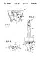
- FIG. 1shows a coronal section through a bone with an artificial joint implant secured to an anchor with a dead man bolt fastened to cortical bone.
- FIG. 2represents an exploded perspective view of an anchor handle and its attachment to the anchor.
- FIG. 3shows the anchor handle viewed from top demonstrating two indexable axes for a drill guide.
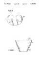
- FIG. 4represents a top view of a template.
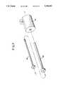
- FIG. 5shows a coronal section of the anchor handle anchor assembly placed through the template in a bone.
- FIG. 6represents a perspective view of an index guide sitting on top of the anchor handle assembly in a coronal plane.
- FIG. 7represents an exploded view of a drill cannula, screw cannula fitting through an index drill guide cannula.
- FIG. 8is a top view of an artificial joint implant adapted for use with the anchor.
- FIG. 9is a coronal section through a typical tubular or appendicular bone.
- FIG. 1shows an implant anchor 20 fastened to cortical bone 22 by dead man 24.
- the anchoris recessed 26 below an artificial joint implant 28 and fastened to the anchor by machine bolts 30.
- FIG. 9represents a cross-section of a typical prepared surface of bone ready to receive an artificial joint implant.
- a hard cortical bone 22encases soft cancellous bone 32 with a transverse cut surface 34.
- a template FIG. 4, No. 36is matched and sized to the transverse bone surface FIG. 9, No. 34 and secured with pins through pin holes 38 to provide temporary fixation.
- An anchor hole in the template FIG. 4, No. 40is used to position the anchor.
- FIG. 2shows the anchor 20 secured to an anchor handle 42 by an anchor handle bolt 44 which threads into an anchor handle bolt hole 46.
- Guide pegs 48align the anchor handle to the anchor by fitting into threaded machine bolt holes 50.
- FIG. 5shows the anchor handle and anchor assembly passed through the anchor hole in the template so that Ledge 1, FIG. 2, No. 52 sits on top of the template FIG. 4, No. 36.
- FIG. 3shows the anchor handle from top projection to be a square configuration oriented so that the diagonal through the handle is parallel to the coronal plane.
- Thisprovides two indexable axes FIG. 3, No. 54 and 56, for alignment of a drill guide, FIG. 6, No. 58.
- the indexable drill guide, FIG. 6 No. 58fits over the anchor handle and sits on Ledge 2, No. 53. This can orient along two axes perpendicular to one another.
- the index drill guideis aligned along Axis 54 so that a cannular guide aligns with the appropriate dead man hole, FIG. 2, No. 62.
- FIG. 7shows a concentric drill cannula 66 fitting into a screw cannula 68 fitting into the cannula guide 60.
- the cannulasare advanced towards bone through the cannula guide.
- a drillis passed through the drill guide near cortex of bone, dead man hole, far cortex of bone and removed.
- the drill cannulais removed leaving the screw cannula in place.
- a large diameter drill matching the diameter of the dead man holeis passed through the near cortex of bone.
- the large drill bitis removed.
- a self tapping dead man screwis placed through the screw cannula into the bone as demonstrated in FIG. 1.
- the index guide, anchor handle, and templateare removed.
- An artificial joint implant FIG. 8is then fastened to the anchor with machine bolts producing compression between the end of the bone and the artificial joint implant.
- the method presentedcan be adapted to the ends of all tubular bones in the appendicular skeleton. Compression can be applied to all metal back prostheses by minor modification of providing holes for the machine bolts FIG. 8, No. 70. This system can be used to fasten artificial joint implants to the ends of all tubular bone.
- This systemwould be feasible for securing the femoral component in the artificial knee implant, the femoral component in the artificial hip implant, the humeral component in the artificial shoulder joint implant, the humeral component in the artificial elbow implant, the ulnar component in the artificial elbow implant, the radial component in the artificial wrist implants, the tibial component in the artificial ankle joints, the proximal and distal ends of the metatarsals and metacarpals, and the proximal and distal ends of the phalanges.
Landscapes
- Health & Medical Sciences (AREA)
- Orthopedic Medicine & Surgery (AREA)
- Life Sciences & Earth Sciences (AREA)
- Animal Behavior & Ethology (AREA)
- Transplantation (AREA)
- Oral & Maxillofacial Surgery (AREA)
- Veterinary Medicine (AREA)
- Engineering & Computer Science (AREA)
- Biomedical Technology (AREA)
- Heart & Thoracic Surgery (AREA)
- Public Health (AREA)
- General Health & Medical Sciences (AREA)
- Surgery (AREA)
- Physical Education & Sports Medicine (AREA)
- Cardiology (AREA)
- Vascular Medicine (AREA)
- Molecular Biology (AREA)
- Medical Informatics (AREA)
- Nuclear Medicine, Radiotherapy & Molecular Imaging (AREA)
- Dentistry (AREA)
- Prostheses (AREA)
Abstract
Description
This system is intended to be used by qualified surgeons in the field of orthopedics in human and veterinary medicine with specific application to artificial joint surgery. The system provides compression fixation of an artificial joint implant to the ends of bone. The current methods used to fix artificial joint implants to bone utilize polymethyl methacrylate bone cement which loosens in time secondary to adjacent tissue reaction of live bone. Poly-methyl methcrylate bone cement has been associated with intraoperative hypotension, allergic reactions, and chemical hepatitis. Another method used to fix artificial joint implants to the ends of bone utilizes intramedullary pegs driven down into the medullary canal of bone. This principle does not provide compression nor does it provide resistance to pull out. Expandable polyethylene pegs have been incorporated into the fixation of artificial joint implants but fail to provide compression and the fixation is dependent upon friction generated between the expandable peg and the friable cancellous bone. Numerous configurations of the artificial joint implant prosthesis base plate have been devised to improve upon fixation but rely primarily upon the strength of the friable cancellous bone. Large cancellous screws placed through the artificial joint implant have been employed but again are limited in their ability to secure the artificial joint implant based upon the limited resistance to pull-out offered by cancellous bone. The anchoring system describe herein provides compression which exceeds that which can be achieved by any current method of fixation. By improving fixation of the artificial joint implant to the ends of bone, facilitate bone ingrowth for physiologic bonding and provides improved resistance against physiologic forces applied across the joint.
The objectives and advantages are achieved by recessing an anchoring device below the level of the osteotomy for the artificial joint implant and securing the anchor to cortical bone by means of a dead man. Once the anchor has been fastened, a metal-backed artificial joint implant can be placed on top of the osteotomy site and secured to the achoring device by means of machine bolts to apply compressive forces. Since the anchor is secured to cortical bone by a dead man, the compressive forces resisting pull-out are determined by the strength of the cortical bone which far exceeds the forces resisting pull-out from cancellous bone.
FIG. 1 shows a coronal section through a bone with an artificial joint implant secured to an anchor with a dead man bolt fastened to cortical bone.
FIG. 2 represents an exploded perspective view of an anchor handle and its attachment to the anchor.
FIG. 3 shows the anchor handle viewed from top demonstrating two indexable axes for a drill guide.
FIG. 4 represents a top view of a template.
FIG. 5 shows a coronal section of the anchor handle anchor assembly placed through the template in a bone.
FIG. 6 represents a perspective view of an index guide sitting on top of the anchor handle assembly in a coronal plane.
FIG. 7 represents an exploded view of a drill cannula, screw cannula fitting through an index drill guide cannula.
FIG. 8 is a top view of an artificial joint implant adapted for use with the anchor.
FIG. 9 is a coronal section through a typical tubular or appendicular bone.
FIG. 1 shows animplant anchor 20 fastened tocortical bone 22 bydead man 24. The anchor is recessed 26 below anartificial joint implant 28 and fastened to the anchor bymachine bolts 30.
FIG. 9 represents a cross-section of a typical prepared surface of bone ready to receive an artificial joint implant. A hardcortical bone 22 encasessoft cancellous bone 32 with atransverse cut surface 34. A template FIG. 4, No. 36 is matched and sized to the transverse bone surface FIG. 9, No. 34 and secured with pins throughpin holes 38 to provide temporary fixation. An anchor hole in the template FIG. 4, No. 40, is used to position the anchor. FIG. 2 shows theanchor 20 secured to ananchor handle 42 by ananchor handle bolt 44 which threads into an anchorhandle bolt hole 46.Guide pegs 48 align the anchor handle to the anchor by fitting into threadedmachine bolt holes 50. FIG. 5 shows the anchor handle and anchor assembly passed through the anchor hole in the template so that Ledge 1, FIG. 2, No. 52 sits on top of the template FIG. 4, No. 36.
FIG. 3 shows the anchor handle from top projection to be a square configuration oriented so that the diagonal through the handle is parallel to the coronal plane. This provides two indexable axes FIG. 3, No. 54 and 56, for alignment of a drill guide, FIG. 6, No. 58. The indexable drill guide, FIG. 6 No. 58, fits over the anchor handle and sits on Ledge 2, No. 53. This can orient along two axes perpendicular to one another. In FIG. 6 the index drill guide is aligned alongAxis 54 so that a cannular guide aligns with the appropriate dead man hole, FIG. 2, No. 62.
FIG. 7 shows a concentric drill cannula 66 fitting into ascrew cannula 68 fitting into thecannula guide 60. The cannulas are advanced towards bone through the cannula guide. A drill is passed through the drill guide near cortex of bone, dead man hole, far cortex of bone and removed. The drill cannula is removed leaving the screw cannula in place. A large diameter drill matching the diameter of the dead man hole is passed through the near cortex of bone. The large drill bit is removed. A self tapping dead man screw is placed through the screw cannula into the bone as demonstrated in FIG. 1. The index guide, anchor handle, and template are removed. An artificial joint implant FIG. 8 is then fastened to the anchor with machine bolts producing compression between the end of the bone and the artificial joint implant.
The method presented can be adapted to the ends of all tubular bones in the appendicular skeleton. Compression can be applied to all metal back prostheses by minor modification of providing holes for the machine bolts FIG. 8, No. 70. This system can be used to fasten artificial joint implants to the ends of all tubular bone. This system would be feasible for securing the femoral component in the artificial knee implant, the femoral component in the artificial hip implant, the humeral component in the artificial shoulder joint implant, the humeral component in the artificial elbow implant, the ulnar component in the artificial elbow implant, the radial component in the artificial wrist implants, the tibial component in the artificial ankle joints, the proximal and distal ends of the metatarsals and metacarpals, and the proximal and distal ends of the phalanges.
Claims (1)
1. An apparatus for retaining a joint implant comprising:
an anchor implantable within a bone, said anchor defining a longitudinal axis and having a lower proximal end and upper distal end, the upper distal end being widened relative to the lower proximal end and defining at least two, spaced, threaded apertures, the lower proximal end defining a single aperture, with said single aperture being angled with respect to said longitudinal axis;
two threaded countersunk bolts connectably engaging two of said apertures in said anchor and extending above the edge of said bone for retaining the implant on the bone edge;
a dead man bolt having a head portion and a threaded portion, said dead man bolt extending through said single angled aperture so that said head and threaded portion of the dead man bolt engage outer cortical portions of the bone and retain the anchor within the bone.
Priority Applications (1)
| Application Number | Priority Date | Filing Date | Title |
|---|---|---|---|
| US07/773,210US5180383A (en) | 1991-10-09 | 1991-10-09 | Method and device for attaching artificial joint implants to the ends of bones |
Applications Claiming Priority (1)
| Application Number | Priority Date | Filing Date | Title |
|---|---|---|---|
| US07/773,210US5180383A (en) | 1991-10-09 | 1991-10-09 | Method and device for attaching artificial joint implants to the ends of bones |
Publications (1)
| Publication Number | Publication Date |
|---|---|
| US5180383Atrue US5180383A (en) | 1993-01-19 |
Family
ID=25097545
Family Applications (1)
| Application Number | Title | Priority Date | Filing Date |
|---|---|---|---|
| US07/773,210Expired - Fee RelatedUS5180383A (en) | 1991-10-09 | 1991-10-09 | Method and device for attaching artificial joint implants to the ends of bones |
Country Status (1)
| Country | Link |
|---|---|
| US (1) | US5180383A (en) |
Cited By (46)
| Publication number | Priority date | Publication date | Assignee | Title |
|---|---|---|---|---|
| WO1996005785A1 (en)* | 1994-08-25 | 1996-02-29 | Birger Roos | A lower extremity prosthesis |
| US5549683A (en)* | 1992-08-06 | 1996-08-27 | Bonutti; Peter M. | Anthroplasty component |
| FR2776506A1 (en)* | 1998-03-25 | 1999-10-01 | Depuy France | Shoulder prosthesis glenoid member and ancillary components |
| US6197065B1 (en) | 1993-11-01 | 2001-03-06 | Biomet, Inc. | Method and apparatus for segmental bone replacement |
| US6387109B1 (en) | 1996-10-17 | 2002-05-14 | Ethicon Endo-Surgery, Inc. | Methods and device for improving blood flow to heart of a patient |
| US6485519B2 (en) | 2001-01-29 | 2002-11-26 | Bristol-Myers Squibb Company | Constrained prosthetic knee with rotating bearing |
| US6620199B2 (en)* | 2001-07-13 | 2003-09-16 | Ronald P. Grelsamer | Device for reinforcing bone in partial knee replacement surgery |
| US6719800B2 (en) | 2001-01-29 | 2004-04-13 | Zimmer Technology, Inc. | Constrained prosthetic knee with rotating bearing |
| US6773461B2 (en) | 2001-01-29 | 2004-08-10 | Zimmer Technology, Inc. | Constrained prosthetic knee with rotating bearing |
| US20050015153A1 (en)* | 2002-05-24 | 2005-01-20 | Medicine Lodge, Inc. | Implants and related methods and apparatus for securing an implant on an articulating surface of an orthopedic joint |
| US20050143831A1 (en)* | 2003-12-30 | 2005-06-30 | Medicinelodge, Inc. | Tibial condylar hemiplasty implants, anchor assemblies, and related methods |
| US20050165395A1 (en)* | 2004-01-23 | 2005-07-28 | Orbay Jorge L. | System for stabilization of fractures of convex articular bone surfaces including subchondral support structure |
| US20050216027A1 (en)* | 2004-03-24 | 2005-09-29 | Suh Sean S | Extraction screwdriver |
| US20060009855A1 (en)* | 2004-07-09 | 2006-01-12 | Medicinelodge, Inc. | Trochlear groove implants and related methods and instruments |
| US20060009774A1 (en)* | 2003-12-30 | 2006-01-12 | Medicinelodge Inc. | Methods for mounting and using tethered joint bearing implants |
| US20060116775A1 (en)* | 1993-11-01 | 2006-06-01 | Biomet Manufacturing Corp. | Compliant fixation for pelvis |
| US20060129247A1 (en)* | 1993-11-01 | 2006-06-15 | Bioment Manufacturing Corp. | Intramedullary compliant fixation |
| US20060161261A1 (en)* | 2004-05-04 | 2006-07-20 | Biomet Manufacturing Corp. | Method and apparatus for constructing a modular acetabulum |
| US20060167756A1 (en)* | 2005-01-21 | 2006-07-27 | Ebay Inc. | Network-based commerce facility offer management methods and systems |
| US20060189987A1 (en)* | 2002-05-30 | 2006-08-24 | Orbay Jorge L | Nail plate |
| US20060189996A1 (en)* | 2005-01-28 | 2006-08-24 | Orbay Jorge L | Nail plate and implantation jig therefor |
| US7141073B2 (en) | 1993-11-01 | 2006-11-28 | Biomet, Inc. | Compliant fixation of external prosthesis |
| US20080314014A1 (en)* | 2005-11-23 | 2008-12-25 | Nicholson Machinery Limited | Method and Apparatus for Topping Vegetables |
| US7670383B1 (en) | 2004-05-04 | 2010-03-02 | Biomet Manufacturing Corp. | Pubic catch |
| US7744638B2 (en) | 2004-01-23 | 2010-06-29 | Depuy Products, Inc. | System for stabilization of fractures of convex articular bone surfaces including subchondral support structure |
| US7780710B2 (en) | 2004-01-23 | 2010-08-24 | Depuy Products, Inc. | System for stabilization of fractures of convex articular bone surfaces including subchondral support structure |
| US20100274245A1 (en)* | 2003-11-21 | 2010-10-28 | Eduardo Gonzalez-Hernandez | Fracture fixation system |
| US20100312350A1 (en)* | 2000-01-14 | 2010-12-09 | Bonutti Peter M | Segmental knee arthroplasty |
| US20110152943A1 (en)* | 2009-12-22 | 2011-06-23 | Eduardo Gonzalez-Hernandez | Bone plate and tool assembly and method for use thereof |
| US20110178604A1 (en)* | 2010-01-18 | 2011-07-21 | Biomet Manufacturing Corp. | Expandable Endoprosthesis |
| US8469999B2 (en) | 2008-04-17 | 2013-06-25 | Eduardo Gonzalez-Hernandez | Soft tissue attachment system and clip |
| US8764808B2 (en) | 2008-03-10 | 2014-07-01 | Eduardo Gonzalez-Hernandez | Bone fixation system |
| US8834490B2 (en) | 2001-08-28 | 2014-09-16 | Bonutti Skeletal Innovations Llc | Method for robotic arthroplasty using navigation |
| US8870963B2 (en) | 2010-10-27 | 2014-10-28 | Toby Orthopaedics, Inc. | System and method for fracture replacement of comminuted bone fractures or portions thereof adjacent bone joints |
| US8915970B2 (en) | 2013-02-08 | 2014-12-23 | Biomet Manufacturing, Llc | Transdermal prosthesis |
| US8961573B2 (en) | 2010-10-05 | 2015-02-24 | Toby Orthopaedics, Inc. | System and method for facilitating repair and reattachment of comminuted bone portions |
| US8968415B2 (en) | 2012-02-07 | 2015-03-03 | Biomet Manufacturing, Llc | Implant fixation device |
| US9132018B1 (en)* | 2013-08-27 | 2015-09-15 | Mohammed A. Hajianpour | Total ankle replacement |
| US9254154B2 (en) | 2011-03-03 | 2016-02-09 | Toby Orthopaedic, Inc. | Anterior lesser tuberosity fixed angle fixation device and method of use associated therewith |
| US9271772B2 (en) | 2011-10-27 | 2016-03-01 | Toby Orthopaedics, Inc. | System and method for fracture replacement of comminuted bone fractures or portions thereof adjacent bone joints |
| US9283008B2 (en) | 2012-12-17 | 2016-03-15 | Toby Orthopaedics, Inc. | Bone plate for plate osteosynthesis and method for use thereof |
| US9333014B2 (en) | 2013-03-15 | 2016-05-10 | Eduardo Gonzalez-Hernandez | Bone fixation and reduction apparatus and method for fixation and reduction of a distal bone fracture and malunion |
| US9402667B2 (en) | 2011-11-09 | 2016-08-02 | Eduardo Gonzalez-Hernandez | Apparatus and method for use of the apparatus for fracture fixation of the distal humerus |
| US20170056186A1 (en)* | 2015-08-31 | 2017-03-02 | Rainer Baumgart | Implantable Prosthesis for Replacing the Human Knee Joint |
| US9730797B2 (en) | 2011-10-27 | 2017-08-15 | Toby Orthopaedics, Inc. | Bone joint replacement and repair assembly and method of repairing and replacing a bone joint |
| US11213334B2 (en) | 2015-10-07 | 2022-01-04 | Stabiliz Orthopaedics, LLC | Bone fracture fixation device with transverse set screw and aiming guide |
Citations (11)
| Publication number | Priority date | Publication date | Assignee | Title |
|---|---|---|---|---|
| US3641590A (en)* | 1970-01-16 | 1972-02-15 | Arthur A Michele | Acetabular replacement prosthesis and method of assembling |
| US3740769A (en)* | 1971-02-11 | 1973-06-26 | E Haboush | Prosthesis for hip joints |
| US3903549A (en)* | 1974-06-12 | 1975-09-09 | William Minor Deyerle | Acetabular cup prosthesis component for total or subtotal hip prosthesis system |
| US3939497A (en)* | 1973-12-28 | 1976-02-24 | Friedrichsfeld Gmbh. Steinzeug-Und Kunststoffwerke | Fastening means for hip joint prosthesis sockets |
| US4754749A (en)* | 1986-04-29 | 1988-07-05 | Tsou Paul M | Surgical screw with counter-rotation prevention means |
| US4944759A (en)* | 1986-01-21 | 1990-07-31 | Joint Medical Products Corporation | Porous-coated artificial joints |
| US4955325A (en)* | 1989-06-14 | 1990-09-11 | Osteonics Corp. | Acetabular cup component cement spacer system |
| US4963153A (en)* | 1987-06-30 | 1990-10-16 | Sulzer Brothers Limited | Metal tibial anchoring part for a partial knee joint prosthesis |
| US4963152A (en)* | 1986-10-27 | 1990-10-16 | Intermedics Orthopedics, Inc. | Asymmetric prosthetic tibial component |
| US4990161A (en)* | 1984-03-16 | 1991-02-05 | Kampner Stanley L | Implant with resorbable stem |
| US5013313A (en)* | 1988-05-30 | 1991-05-07 | Patrick Surer | Device for fixation of part on a support, especially of an implant on a bone |
- 1991
- 1991-10-09USUS07/773,210patent/US5180383A/ennot_activeExpired - Fee Related
Patent Citations (11)
| Publication number | Priority date | Publication date | Assignee | Title |
|---|---|---|---|---|
| US3641590A (en)* | 1970-01-16 | 1972-02-15 | Arthur A Michele | Acetabular replacement prosthesis and method of assembling |
| US3740769A (en)* | 1971-02-11 | 1973-06-26 | E Haboush | Prosthesis for hip joints |
| US3939497A (en)* | 1973-12-28 | 1976-02-24 | Friedrichsfeld Gmbh. Steinzeug-Und Kunststoffwerke | Fastening means for hip joint prosthesis sockets |
| US3903549A (en)* | 1974-06-12 | 1975-09-09 | William Minor Deyerle | Acetabular cup prosthesis component for total or subtotal hip prosthesis system |
| US4990161A (en)* | 1984-03-16 | 1991-02-05 | Kampner Stanley L | Implant with resorbable stem |
| US4944759A (en)* | 1986-01-21 | 1990-07-31 | Joint Medical Products Corporation | Porous-coated artificial joints |
| US4754749A (en)* | 1986-04-29 | 1988-07-05 | Tsou Paul M | Surgical screw with counter-rotation prevention means |
| US4963152A (en)* | 1986-10-27 | 1990-10-16 | Intermedics Orthopedics, Inc. | Asymmetric prosthetic tibial component |
| US4963153A (en)* | 1987-06-30 | 1990-10-16 | Sulzer Brothers Limited | Metal tibial anchoring part for a partial knee joint prosthesis |
| US5013313A (en)* | 1988-05-30 | 1991-05-07 | Patrick Surer | Device for fixation of part on a support, especially of an implant on a bone |
| US4955325A (en)* | 1989-06-14 | 1990-09-11 | Osteonics Corp. | Acetabular cup component cement spacer system |
Cited By (95)
| Publication number | Priority date | Publication date | Assignee | Title |
|---|---|---|---|---|
| US5549683A (en)* | 1992-08-06 | 1996-08-27 | Bonutti; Peter M. | Anthroplasty component |
| US7141073B2 (en) | 1993-11-01 | 2006-11-28 | Biomet, Inc. | Compliant fixation of external prosthesis |
| US7476254B2 (en) | 1993-11-01 | 2009-01-13 | Biomet Manufacturing Corporation | Compliant fixation for pelvis |
| US6197065B1 (en) | 1993-11-01 | 2001-03-06 | Biomet, Inc. | Method and apparatus for segmental bone replacement |
| US6508841B2 (en) | 1993-11-01 | 2003-01-21 | Biomet, Inc. | Method and apparatus for segmental bone replacement |
| US7722678B2 (en) | 1993-11-01 | 2010-05-25 | Biomet Manufacturing Corp. | Intramedullary compliant fixation |
| US20060129247A1 (en)* | 1993-11-01 | 2006-06-15 | Bioment Manufacturing Corp. | Intramedullary compliant fixation |
| US6712855B2 (en)* | 1993-11-01 | 2004-03-30 | Biomet, Inc. | Compliant tibial tray assembly |
| US20060116775A1 (en)* | 1993-11-01 | 2006-06-01 | Biomet Manufacturing Corp. | Compliant fixation for pelvis |
| WO1996005785A1 (en)* | 1994-08-25 | 1996-02-29 | Birger Roos | A lower extremity prosthesis |
| US5888215A (en)* | 1994-08-25 | 1999-03-30 | Roos; Birger | Lower extremity prosthesis |
| US6387109B1 (en) | 1996-10-17 | 2002-05-14 | Ethicon Endo-Surgery, Inc. | Methods and device for improving blood flow to heart of a patient |
| FR2776506A1 (en)* | 1998-03-25 | 1999-10-01 | Depuy France | Shoulder prosthesis glenoid member and ancillary components |
| US9192459B2 (en) | 2000-01-14 | 2015-11-24 | Bonutti Skeletal Innovations Llc | Method of performing total knee arthroplasty |
| US8784495B2 (en) | 2000-01-14 | 2014-07-22 | Bonutti Skeletal Innovations Llc | Segmental knee arthroplasty |
| US9101443B2 (en) | 2000-01-14 | 2015-08-11 | Bonutti Skeletal Innovations Llc | Methods for robotic arthroplasty |
| US20100312350A1 (en)* | 2000-01-14 | 2010-12-09 | Bonutti Peter M | Segmental knee arthroplasty |
| US9795394B2 (en) | 2000-01-14 | 2017-10-24 | Bonutti Skeletal Innovations Llc | Method for placing implant using robotic system |
| US6485519B2 (en) | 2001-01-29 | 2002-11-26 | Bristol-Myers Squibb Company | Constrained prosthetic knee with rotating bearing |
| US8268006B2 (en) | 2001-01-29 | 2012-09-18 | Zimmer, Inc. | Constrained prosthetic knee with rotating bearing |
| USRE44476E1 (en) | 2001-01-29 | 2013-09-03 | Zimmer, Inc. | Constrained prosthetic knee with rotating bearing |
| US20040249467A1 (en)* | 2001-01-29 | 2004-12-09 | Meyers John E. | Constrained prosthetic knee with rotating bearing |
| US6773461B2 (en) | 2001-01-29 | 2004-08-10 | Zimmer Technology, Inc. | Constrained prosthetic knee with rotating bearing |
| US6719800B2 (en) | 2001-01-29 | 2004-04-13 | Zimmer Technology, Inc. | Constrained prosthetic knee with rotating bearing |
| US8888857B2 (en) | 2001-01-29 | 2014-11-18 | Zimmer, Inc. | Constrained prosthetic knee with rotating bearing |
| US6620199B2 (en)* | 2001-07-13 | 2003-09-16 | Ronald P. Grelsamer | Device for reinforcing bone in partial knee replacement surgery |
| US8834490B2 (en) | 2001-08-28 | 2014-09-16 | Bonutti Skeletal Innovations Llc | Method for robotic arthroplasty using navigation |
| US9763683B2 (en) | 2001-08-28 | 2017-09-19 | Bonutti Skeletal Innovations Llc | Method for performing surgical procedures using optical cutting guides |
| US10231739B1 (en) | 2001-08-28 | 2019-03-19 | Bonutti Skeletal Innovations Llc | System and method for robotic surgery |
| US9060797B2 (en) | 2001-08-28 | 2015-06-23 | Bonutti Skeletal Innovations Llc | Method of preparing a femur and tibia in knee arthroplasty |
| US10321918B2 (en) | 2001-08-28 | 2019-06-18 | Bonutti Skeletal Innovations Llc | Methods for robotic surgery using a cannula |
| US8858557B2 (en) | 2001-08-28 | 2014-10-14 | Bonutti Skeletal Innovations Llc | Method of preparing a femur and tibia in knee arthroplasty |
| US8840629B2 (en) | 2001-08-28 | 2014-09-23 | Bonutti Skeletal Innovations Llc | Robotic arthroplasty system including navigation |
| US10470780B2 (en) | 2001-08-28 | 2019-11-12 | Bonutti Skeletal Innovations Llc | Systems and methods for ligament balancing in robotic surgery |
| US20050015153A1 (en)* | 2002-05-24 | 2005-01-20 | Medicine Lodge, Inc. | Implants and related methods and apparatus for securing an implant on an articulating surface of an orthopedic joint |
| US7922772B2 (en) | 2002-05-24 | 2011-04-12 | Zimmer, Inc. | Implants and related methods and apparatus for securing an implant on an articulating surface of an orthopedic joint |
| US7938850B2 (en) | 2002-05-30 | 2011-05-10 | Depuy Products, Inc. | Nail plate |
| US20060189987A1 (en)* | 2002-05-30 | 2006-08-24 | Orbay Jorge L | Nail plate |
| US20100274245A1 (en)* | 2003-11-21 | 2010-10-28 | Eduardo Gonzalez-Hernandez | Fracture fixation system |
| US8574234B2 (en) | 2003-11-21 | 2013-11-05 | Toby Orthopaedics, Inc. | Fracture fixation system |
| US8361075B2 (en) | 2003-11-21 | 2013-01-29 | Toby Orthopaedics, Inc. | Method for repairing fractured bone |
| US8182485B1 (en) | 2003-11-21 | 2012-05-22 | Toby Orthopaedics, Llc | Fracture fixation system |
| US7462199B2 (en)* | 2003-12-30 | 2008-12-09 | Medicinelodge, Inc. | Methods for mounting a tibial condylar implant |
| US20060009774A1 (en)* | 2003-12-30 | 2006-01-12 | Medicinelodge Inc. | Methods for mounting and using tethered joint bearing implants |
| US20060004461A1 (en)* | 2003-12-30 | 2006-01-05 | Medicinelodge, Inc. | Methods for mounting a tibial condylar implant |
| US8236060B2 (en) | 2003-12-30 | 2012-08-07 | Zimmer, Inc. | Tethered joint bearing implants and systems |
| US7867280B2 (en) | 2003-12-30 | 2011-01-11 | Zimmer, Inc. | Methods for mounting and using tethered joint bearing implants |
| US20050143831A1 (en)* | 2003-12-30 | 2005-06-30 | Medicinelodge, Inc. | Tibial condylar hemiplasty implants, anchor assemblies, and related methods |
| US7001388B2 (en) | 2004-01-23 | 2006-02-21 | Hand Innovations, Llc | System for stabilization of fractures of convex articular bone surfaces including subchondral support structure |
| US7780710B2 (en) | 2004-01-23 | 2010-08-24 | Depuy Products, Inc. | System for stabilization of fractures of convex articular bone surfaces including subchondral support structure |
| US20050165395A1 (en)* | 2004-01-23 | 2005-07-28 | Orbay Jorge L. | System for stabilization of fractures of convex articular bone surfaces including subchondral support structure |
| US7744638B2 (en) | 2004-01-23 | 2010-06-29 | Depuy Products, Inc. | System for stabilization of fractures of convex articular bone surfaces including subchondral support structure |
| US20050216027A1 (en)* | 2004-03-24 | 2005-09-29 | Suh Sean S | Extraction screwdriver |
| US8048166B2 (en) | 2004-05-04 | 2011-11-01 | Biomet Manufacturing Corp. | Method and apparatus for constructing a modular acetabulum |
| US7670383B1 (en) | 2004-05-04 | 2010-03-02 | Biomet Manufacturing Corp. | Pubic catch |
| US20060161261A1 (en)* | 2004-05-04 | 2006-07-20 | Biomet Manufacturing Corp. | Method and apparatus for constructing a modular acetabulum |
| US20060009855A1 (en)* | 2004-07-09 | 2006-01-12 | Medicinelodge, Inc. | Trochlear groove implants and related methods and instruments |
| US8157867B2 (en) | 2004-07-09 | 2012-04-17 | Zimmer, Inc. | Trochlear groove implants and related methods and instruments |
| US8852195B2 (en) | 2004-07-09 | 2014-10-07 | Zimmer, Inc. | Guide templates for surgical implants and related methods |
| US20060167756A1 (en)* | 2005-01-21 | 2006-07-27 | Ebay Inc. | Network-based commerce facility offer management methods and systems |
| US7896886B2 (en) | 2005-01-28 | 2011-03-01 | Depuy Products, Inc. | Nail plate and implantation jig therefor |
| US7927341B2 (en) | 2005-01-28 | 2011-04-19 | Depuy Products, Inc. | Nail plate and jig therefor |
| US20060200157A1 (en)* | 2005-01-28 | 2006-09-07 | Orbay Jorge L | Nail Plate and Jig Therefor |
| US20060189996A1 (en)* | 2005-01-28 | 2006-08-24 | Orbay Jorge L | Nail plate and implantation jig therefor |
| US20080314014A1 (en)* | 2005-11-23 | 2008-12-25 | Nicholson Machinery Limited | Method and Apparatus for Topping Vegetables |
| US8764808B2 (en) | 2008-03-10 | 2014-07-01 | Eduardo Gonzalez-Hernandez | Bone fixation system |
| US8690916B2 (en) | 2008-04-17 | 2014-04-08 | Eduardo Gonzalez-Hernandez | Soft tissue attachment system and clip |
| US8469999B2 (en) | 2008-04-17 | 2013-06-25 | Eduardo Gonzalez-Hernandez | Soft tissue attachment system and clip |
| US20110152943A1 (en)* | 2009-12-22 | 2011-06-23 | Eduardo Gonzalez-Hernandez | Bone plate and tool assembly and method for use thereof |
| US20110178604A1 (en)* | 2010-01-18 | 2011-07-21 | Biomet Manufacturing Corp. | Expandable Endoprosthesis |
| US8961573B2 (en) | 2010-10-05 | 2015-02-24 | Toby Orthopaedics, Inc. | System and method for facilitating repair and reattachment of comminuted bone portions |
| US9271776B2 (en) | 2010-10-05 | 2016-03-01 | Toby Orthopaedics, Inc. | System and method for facilitating repair and reattachment of comminuted bone portions |
| US9757240B2 (en) | 2010-10-27 | 2017-09-12 | Toby Orthopaedics, Inc. | System and method for fracture replacement of comminuted bone fractures or portions thereof adjacent bone joints |
| US11266506B2 (en) | 2010-10-27 | 2022-03-08 | Toby Orthopaedics, Inc. | System for fracture replacement of comminuted bone fractures or portions thereof adjacent bone joints |
| US10524919B2 (en) | 2010-10-27 | 2020-01-07 | Toby Orthopaedics, Inc. | System and method for fracture replacement of comminuted bone fractures or portions thereof adjacent bone joints |
| US8870963B2 (en) | 2010-10-27 | 2014-10-28 | Toby Orthopaedics, Inc. | System and method for fracture replacement of comminuted bone fractures or portions thereof adjacent bone joints |
| US9254154B2 (en) | 2011-03-03 | 2016-02-09 | Toby Orthopaedic, Inc. | Anterior lesser tuberosity fixed angle fixation device and method of use associated therewith |
| US10188522B2 (en) | 2011-10-27 | 2019-01-29 | Toby Orthopaedics, Inc. | System for replacement of at least a portion of a carpal articular surface of a radius |
| US11285020B2 (en) | 2011-10-27 | 2022-03-29 | Toby Orthopaedics, Inc. | Bone joint replacement and repair assembly and method of repairing and replacing a bone joint |
| US9271772B2 (en) | 2011-10-27 | 2016-03-01 | Toby Orthopaedics, Inc. | System and method for fracture replacement of comminuted bone fractures or portions thereof adjacent bone joints |
| US10299939B2 (en) | 2011-10-27 | 2019-05-28 | Toby Orthopaedics, Inc. | Bone joint replacement and repair assembly and method of repairing and replacing a bone joint |
| US9730797B2 (en) | 2011-10-27 | 2017-08-15 | Toby Orthopaedics, Inc. | Bone joint replacement and repair assembly and method of repairing and replacing a bone joint |
| US11129723B2 (en) | 2011-10-27 | 2021-09-28 | Toby Orthopaedics, Inc | System and method for fracture replacement of comminuted bone fractures or portions thereof adjacent bone joints |
| US9402667B2 (en) | 2011-11-09 | 2016-08-02 | Eduardo Gonzalez-Hernandez | Apparatus and method for use of the apparatus for fracture fixation of the distal humerus |
| US8968415B2 (en) | 2012-02-07 | 2015-03-03 | Biomet Manufacturing, Llc | Implant fixation device |
| US10835302B2 (en) | 2012-12-17 | 2020-11-17 | Toby Orthopaedics, Inc. | Bone plate for plate osteosynthesis and method for use thereof |
| US11583324B2 (en) | 2012-12-17 | 2023-02-21 | Toby Orthopaedics, Llc | Bone plate for plate osteosynthesis and method for use thereof |
| US9956017B2 (en) | 2012-12-17 | 2018-05-01 | Toby Orthopaedics, Inc. | Bone plate for plate osteosynthesis and method for use thereof |
| US9283008B2 (en) | 2012-12-17 | 2016-03-15 | Toby Orthopaedics, Inc. | Bone plate for plate osteosynthesis and method for use thereof |
| US8915970B2 (en) | 2013-02-08 | 2014-12-23 | Biomet Manufacturing, Llc | Transdermal prosthesis |
| US9333014B2 (en) | 2013-03-15 | 2016-05-10 | Eduardo Gonzalez-Hernandez | Bone fixation and reduction apparatus and method for fixation and reduction of a distal bone fracture and malunion |
| US9132018B1 (en)* | 2013-08-27 | 2015-09-15 | Mohammed A. Hajianpour | Total ankle replacement |
| US10136996B2 (en)* | 2015-08-31 | 2018-11-27 | Rainer Baumgart | Implantable prosthesis for replacing the human knee joint |
| US20170056186A1 (en)* | 2015-08-31 | 2017-03-02 | Rainer Baumgart | Implantable Prosthesis for Replacing the Human Knee Joint |
| US11213334B2 (en) | 2015-10-07 | 2022-01-04 | Stabiliz Orthopaedics, LLC | Bone fracture fixation device with transverse set screw and aiming guide |
Similar Documents
| Publication | Publication Date | Title |
|---|---|---|
| US5180383A (en) | Method and device for attaching artificial joint implants to the ends of bones | |
| US10874435B2 (en) | Bone securement apparatus and method | |
| EP0906065B1 (en) | Intermedullary rod apparatus for repairing proximal humerus fractures | |
| US5693055A (en) | Odd angle internal bone fixation device | |
| US9700359B2 (en) | Locking plate with screw fixation from opposite cortex | |
| CA2587373C (en) | Endosteal nail | |
| US8388690B2 (en) | Osteotomy system | |
| US5112336A (en) | Drill guide and template for prosthetic devices | |
| EP4480427A2 (en) | Intramedullary nail fixation systems | |
| US20090093849A1 (en) | Metatarsal fixation system | |
| US20110009865A1 (en) | Bone fixation using an intramedullary pin | |
| JP2007090094A (en) | Surgical fastener assembly | |
| AU2015364631B2 (en) | Bone screw | |
| WO2010062379A1 (en) | Bone fracture fixation screws, systems and methods of use | |
| CA2490963C (en) | Implant systems with fastener for mounting on an articulation surface of an orthopedic joint | |
| WO2023023161A1 (en) | Bone fixation devices, systems, and methods | |
| US4682590A (en) | Method of inserting intramedullary coupled pin | |
| US11490886B2 (en) | Bone fixation system | |
| US20190029742A1 (en) | Devices, systems, and methods for acetabular fracture fixation using a limited open surgical approach | |
| US20230043647A1 (en) | Fastener and method | |
| RU2766250C1 (en) | Implant for replacing the area of a bone defect on the anterior surface of the glenoid of the shoulder blade and a manipulator for its installation | |
| JP2023105819A (en) | Systems and methods for intramedullary nail implantation | |
| Ali et al. | Radiological and Clinical Outcome of Volar Barton Distal Radius Fractures Treated by Variable Angle Volar Locking-Plates (Chinese Version) | |
| CN214318118U (en) | A fracture fixation system | |
| Green | External fixation mounting strategies for difficult locations |
Legal Events
| Date | Code | Title | Description |
|---|---|---|---|
| REMI | Maintenance fee reminder mailed | ||
| REFU | Refund | Free format text:REFUND OF EXCESS PAYMENTS PROCESSED (ORIGINAL EVENT CODE: R169); ENTITY STATUS OF PATENT OWNER: SMALL ENTITY | |
| FPAY | Fee payment | Year of fee payment:4 | |
| SULP | Surcharge for late payment | ||
| LAPS | Lapse for failure to pay maintenance fees | ||
| FP | Lapsed due to failure to pay maintenance fee | Effective date:19970122 | |
| STCH | Information on status: patent discontinuation | Free format text:PATENT EXPIRED DUE TO NONPAYMENT OF MAINTENANCE FEES UNDER 37 CFR 1.362 |