US5180367A - Procedure and balloon catheter system for relieving arterial or veinal restrictions without exchanging balloon catheters - Google Patents
Procedure and balloon catheter system for relieving arterial or veinal restrictions without exchanging balloon cathetersDownload PDFInfo
- Publication number
- US5180367A US5180367AUS07/759,612US75961291AUS5180367AUS 5180367 AUS5180367 AUS 5180367AUS 75961291 AUS75961291 AUS 75961291AUS 5180367 AUS5180367 AUS 5180367A
- Authority
- US
- United States
- Prior art keywords
- balloon
- catheter
- balloon catheter
- distal end
- proximal end
- Prior art date
- Legal status (The legal status is an assumption and is not a legal conclusion. Google has not performed a legal analysis and makes no representation as to the accuracy of the status listed.)
- Expired - Lifetime
Links
Images


Classifications
- A—HUMAN NECESSITIES
- A61—MEDICAL OR VETERINARY SCIENCE; HYGIENE
- A61M—DEVICES FOR INTRODUCING MEDIA INTO, OR ONTO, THE BODY; DEVICES FOR TRANSDUCING BODY MEDIA OR FOR TAKING MEDIA FROM THE BODY; DEVICES FOR PRODUCING OR ENDING SLEEP OR STUPOR
- A61M25/00—Catheters; Hollow probes
- A61M25/10—Balloon catheters
- A61M25/104—Balloon catheters used for angioplasty
- A—HUMAN NECESSITIES
- A61—MEDICAL OR VETERINARY SCIENCE; HYGIENE
- A61M—DEVICES FOR INTRODUCING MEDIA INTO, OR ONTO, THE BODY; DEVICES FOR TRANSDUCING BODY MEDIA OR FOR TAKING MEDIA FROM THE BODY; DEVICES FOR PRODUCING OR ENDING SLEEP OR STUPOR
- A61M25/00—Catheters; Hollow probes
- A61M2025/0004—Catheters; Hollow probes having two or more concentrically arranged tubes for forming a concentric catheter system
- A—HUMAN NECESSITIES
- A61—MEDICAL OR VETERINARY SCIENCE; HYGIENE
- A61M—DEVICES FOR INTRODUCING MEDIA INTO, OR ONTO, THE BODY; DEVICES FOR TRANSDUCING BODY MEDIA OR FOR TAKING MEDIA FROM THE BODY; DEVICES FOR PRODUCING OR ENDING SLEEP OR STUPOR
- A61M25/00—Catheters; Hollow probes
- A61M25/01—Introducing, guiding, advancing, emplacing or holding catheters
- A61M2025/0177—Introducing, guiding, advancing, emplacing or holding catheters having external means for receiving guide wires, wires or stiffening members, e.g. loops, clamps or lateral tubes
- A—HUMAN NECESSITIES
- A61—MEDICAL OR VETERINARY SCIENCE; HYGIENE
- A61M—DEVICES FOR INTRODUCING MEDIA INTO, OR ONTO, THE BODY; DEVICES FOR TRANSDUCING BODY MEDIA OR FOR TAKING MEDIA FROM THE BODY; DEVICES FOR PRODUCING OR ENDING SLEEP OR STUPOR
- A61M25/00—Catheters; Hollow probes
- A61M25/01—Introducing, guiding, advancing, emplacing or holding catheters
- A61M2025/0183—Rapid exchange or monorail catheters
Definitions
- this inventionrelates to a medical procedure for enlarging the cross sectional area of a section of a fluid flow passageway.
- the inventionalso covers the system for performing said procedure.
- PTCApercutaneous transluminal coronary angioplasty procedure
- angioplastyis most frequently called for when blood flow through one or more coronary arteries is severely restricted as the result of the accumulation of plaque deposits on the artery walls.
- a stenosisAn accumulated deposit which results in the constriction or narrowing of the flow path is called a stenosis.
- the object of angioplastyis to enlarge or dilate the stenosis, and the procedure is normally accomplished by use of dilatation catheters.
- angioplastyinvolves enlarging or dilating a restricted or stenotic region of a coronary artery or vessel. This is generally accomplished by inserting a dilatation catheter into the vascular system, feeding it through that system until the balloon at the distal end is within the stenosis.
- distaland proximal are as viewed from the vantage point of the physician who is inserting the device. In other words, the end of the catheter which remains outside of the patient's body is the proximal end and the working end, the one with the balloon that is placed within the stenosis, is the distal end.
- fluidoften contrast medium, under pressure is introduced through the catheter tube into the balloon chamber.
- the expansion of the balloon chambertends to compress the stenosis against the vascular wall. Thereafter, reducing the pressure and thereby collapsing the balloon leaves an enlarged flow path for the passage of blood.
- the proceduremust be repeated one or more times with successively larger balloons. It is frequently the case that the stenosis is so large and the restriction so severe that only the smallest balloon, commonly known as a predilatation catheter, and referred to herein as a pilot balloon or pilot catheter, can be placed within the affected region. That pilot balloon, however, may not be large enough to dilate the stenosis sufficiently to permit adequate blood flow therethrough. However, by using a pilot balloon to begin the enlarging process, room is made to allow insertion of a larger diameter PTCA balloon.
- a physicianIn performing angioplasty a physician will often first introduce a guide wire into the vascular system and feed it through the vascular tree until the end is in or through the stenosis. Then the balloon catheter, most commonly of a dual lumen design, will be passed over the guide wire and will follow that wire to the stenotic region. Thereafter, when the exchange of balloons is to be made, the first catheter is removed, leaving the guide wire in place, and the second catheter is then fed over the wire to the stenotic region.
- the guide wireIn order to accomplish that exchange employing traditional techniques, the guide wire must extend outside of the patient's body a distance at least equal to the length of the catheter. Generally, such a guide wire may be on the order of 300 cm., with half that length or more outside the body. A dangling guide wire of that length outside the body presents obvious problems. It can get in the way of those performing the procedure. It can easily fall to the floor and become contaminated. In addition, it is much more difficult to manipulate than is a shorter one.
- British patent No. 2,180,454describes a two-piece detachable guide wire system which permits removal of the long external portion of the guide wire when it is no longer needed.
- the instant inventioncontemplates permitting the pilot catheter to remain resident in the vascular system, with the balloon portion thereof, if desired, still within the stenotic region, while feeding the second, larger diameter PTCA catheter over the pilot catheter.
- the procedure of the instant inventionrequires less manipulation of devices within the vascular system and hence reduces the risk of trauma. It also permits insertion of the predilatation or pilot catheter alone without giving up the ability to insert a PTCA catheter thereafter except by catheter exchange. In addition, the long guide wire is no longer needed.
- At least one drawback to this system and procedureis that it requires insertion of the large diameter PTCA catheter every time the smaller catheter is to be used. It also calls upon the physician to anticipate in which of his/her cases there is likely to be difficulty in advancing the large diameter PTCA catheter. If such difficulties are not anticipated, this system is not recommended. Unfortunately, the state of the art of fluoroscopy is not far enough advanced to make such predictions entirely reliable. With the instant invention, however, because the pilot catheter is inserted first, it is anticipated that its system and procedure can be employed irrespective of whether difficulties are anticipated.
- the instant inventioncovers a catheter system and a medical procedure wherein a balloon exchange is made unnecessary, which system and procedure, however, are different from and avoid the drawbacks of those disclosed in the above-noted Jang patents and in the PCT applications.
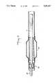
- FIG. 1is a side elevational view of a first, small diameter, pilot balloon catheter useful in practicing the instant invention.
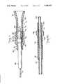
- FIG. 2is a side elevational view of a second, larger diameter, balloon catheter useful in practicing the instant invention.
- FIG. 3is an enlarged side elevation, with parts cut away, of the distal end of the catheter depicted in FIG. 2.
- FIG. 4is an enlarged side elevation, with parts cut away, of an alternative embodiment of the distal end of a second, larger diameter, balloon catheter useful in practicing the instant invention.
- FIG. 4Ais a cross sectional view of the catheter of FIG. 4 taken along cutting line 4A--4A.
- FIG. 5is a side elevational view, with parts cut away, of another alternative embodiment of the distal end of a second, larger diameter, balloon catheter useful in practicing the invention.
- FIG. 5Ais a cross-sectional view of the catheter of FIG. 5 taken along cutting line 5A--5A.
- FIG. 6is a side elevational view, with parts cut away, of yet another alternative embodiment of the distal end of a second, larger diameter, balloon catheter useful in practicing the instant invention.
- FIG. 7is a side elevational view, with parts cut away, of yet another alternative embodiment of the second, larger diameter, balloon catheter useful in practicing the instant invention.
- FIG. 8is a side elevational view, with parts cut away, of the distal end of the catheter of FIG. 2 showing how it is passed over a pilot catheter.
- FIG. 9is a side elevational view of a pilot catheter as the distal end of the second catheter is sliding along same.
- FIG. 10is a side elevational view of a guiding catheter, with the pilot catheter tube, over a guide wire, resident therein, as the distal end of the second catheter is sliding along the pilot catheter tube.
- FIG. 11is a cross sectioned side elevation of a removable liner fitting useful in practicing the invention.
- FIG. 12is an enlarged cross sectioned side elevation of the proximal end of the catheter tube and compression sleeve assembly of FIG. 10.
- a pilot catheter 10 useful in practicing the instant inventionhas a distal end 12 and a proximal end 14. At or near the distal end there is located an inflatable balloon membrane 16. Detachably affixed in fluid-tight fashion to the proximal end is a female luer-type fitting 20. Running from fitting 20 to balloon 16 is a hollow catheter tube 22. The lumen of tube 22 opens into fitting 20 at one end and into balloon chamber 18 at the other. The distal end may also be provided with a flexible steering tip 24 to facilitate proper feeding and placement.
- Fitting 20is designed to accept, in fluid tight fashion, means, for example, a syringe (not shown), for forcing fluid under pressure into the lumen of tube 22.
- a syringe(not shown)
- the application of such pressurecauses balloon membrane 16 to expand and define chamber 18. Removing that source of fluid pressure and applying a partial vacuum causes the balloon membrane to collapse.
- fitting 20is made to be removable from and reattachable to tube 22.
- fitting 20can be removed from tube 22 by cutting the latter.
- FIG. 11Suitable structure for removable fitting 20 is shown in FIG. 11. It has a compression cap 82 and a luer lock body 84.
- Cap 82has a hollow passageway therethrough with a large diameter proximal segment 86 having an internal thread 88 and a smaller diameter distal segment 90.
- Body 84also has a hollow passageway therethrough with the distal segment 92 thereof being cylindrical and the proximal end 94 being frusto-conically shaped so as to accept, in fluid-tight engagement, fluid-pressure generating means such as a syringe (not shown).
- Body 84is also provided with an external thread 96 at its distal end to engage thread 88 in cap 82.
- body 84is threaded into cap 82 their respective through passages are coaxial and in communication with one another.
- a deformable compression sleeve 98is provided to fit over catheter tube 22.
- steel reinforcing tube 100is provided to fit inside the proximal end of tube 22.
- Sleeve 98has a distal cylindrical portion 102, a proximal cylindrical portion 104 and an enlarged head or seal portion 106 between the two.
- Cylindrical portion 102is sized to slide in distal segment 90 of the passage through cap 82.
- Cylindrical portion 104 of sleeve 98is sized to slide in distal segment 92 of the passageway of body 84.
- Seal 106is too large to fit into either segment 90 or segment 92.
- Seal 106has converging sloping faces 108 and 110.
- the transition from proximal segment 86 to distal segment 90 of the passageway through cap 82is by means of a taper having the same slope as that of face 108 of seal 106.
- the distal end of the passageway through body 84is provided with an internal taper having the same slope as that of face 110 of seal 106.
- seal 106is compressed inwardly against catheter tube 12 to form a fluid-tight seal.
- Steel tube 100is provided to prevent collapse of tube 12 when the seal is compressed against it.
- cap 82In order to remove fitting 20, cap 82 is rotated counter-clockwise relative to body 84 in order to relieve the compressive force on seal 106. Then the entire fitting assembly, including sleeve 98, is slid off catheter tube 22.
- the procedure and system of the subject inventioncan be employed in conjunction with or without a guide wire.
- the fitting of FIG. 11is for use without a guide wire.
- a Y fittingwould be employed instead of the straight fitting of FIG. 11.
- Such a Y fittingwould have a second compressive seal proximal to the leg of the Y and could also incorporate means for grabbing and manipulating the guide wire.
- Suitable structure for a Y fitting of that typeis disclosed in co-pending application entitled "Angioplasty Balloon Catheter with Captive Safety Guide" application Ser. No. 403,497 being filed concurrently herewith by one of the instant inventors.
- the second, larger diameter catheter 26is of somewhat similar design to that of pilot catheter 10. It has a distal end 28 and a proximal end 30. At the proximal end is another female luer-type fitting 32 similar to fitting 20, but one which is not removable. At or near distal end 28 is a second balloon membrane 34, and between fitting 32 and balloon 34 is hollow catheter tube 38. The lumen of tube 38 opens into fitting 32 at one end and into balloon chamber 36 at the other.
- the second balloon membrane 34can be expanded by application of fluid under pressure to the lumen of tube 38, thereby to define chamber 36. Such can be accomplished by connecting fluid pressure application means, for example, a syringe (not shown), to fitting 32.
- fluid pressure application meansfor example, a syringe (not shown)
- outer sliding guide means 42in the form of a hollow tube, are provided. As seen in FIG. 3, these sliding guide means run through the interior of balloon chamber 36. Communication between the lumen of tube 38 and chamber 36 is accomplished by providing ports 46 in that portion of tube 38 which is within the chamber.
- Sliding guide means 42are depicted in FIG. 3 as running through the interior of tube 38 from the tip end 40 through chamber 36 and exiting at 44 through the wall of tube 38 just proximate to the proximal end of membrane 34.
- the sliding guide means 52can start at tip end entrance 50, thence run, within chamber 36, alongside of tube 41 in region X and ending at 54 immediately upon exiting from the proximal end of chamber 36.
- the catheter tube 41 shown in FIG. 4has multiple lumens 35, 37 and 39. Lumens 35 and 37 communicate with chamber 36 for expanding and collapsing membrane 34. Lumen 39 can be made to accommodate a stiffening wire (not shown). The stiffening wire can be made to be removable, thereby to enable the physician to vary the flexibility of the PTCA catheter to accommodate to the needs of the particular case. The stiffening wire can also serve to transmit at least some of the axial force necessary to advance the balloon through the arterial tree. To facilitate use of the stiffening wire it is believed most advantageous to taper its distal end from the main body diameter, which may range from about 0.012 inches to 0.016 inches, down to as small as about 0.004 inches.
- FIGS. 5 and 5AA second alternative embodiment is depicted in FIGS. 5 and 5A, where the sliding guide means 60 begins at tip 58, terminates at 62, immediately adjacent the proximal end of chamber 36.
- the sliding guide means 60runs along the outside of membrane 34.
- the flexible distal tip portion(43, 56 and 64 respectively) can form part of the sliding guide means.
- FIG. 6depicts yet another embodiment.
- the sliding guide means 66are extremely short, perhaps 0.25 inches, extending only about the length of the flexible tip 68 and running alongside thereof.
- the sliding guide meansconsists of a small loop 69. While the loop could be in the form of a rigid ring of fixed dimension made, for example, of stainless steel or hard plastic, it may be preferable for it to be of flexible material. Biocompatible plastic line of between 0.002 and 0.10 inches O.D. would be suitable.
- the loop materialcould be affixed to the distal end of a resident push-support wire 71. It is believed most desireable for the wire 71 to be rotatable and axially moveable within tip 28.
- sliding guide meansare shown in the FIGS., one feature they all have in common is that each is much shorter than the catheter tube/balloon combination with which it operates. It is anticipated that the sliding guide means will never be longer than about 50% of the overall length of the entire device, and seldom, if ever, longer than 20% of that length. Instead, normally the sliding guide means will be only slightly longer than the length of the balloon chamber. Because the sliding guide means are short, most of the main body of the pilot catheter will be outside of the PTCA catheter.
- sliding guide means 52might be about 0.034 inches and the outside diameter of pilot tube 22 about 0.032 inches. Pilot balloons range from about 0.020 to 0.030 inches when collapsed, and from as small as about 0.060 inches to as large as about 0.160 inches when fully expanded.
- the larger or PTCA balloonmight range from about 0.047 inches to 0.060 inches when collapsed and from about 0.080 inches to about 0.160 inches when fully expanded.
- the outside diameter of the second tube 38might be about 0.040 inches.
- the method of the instant inventionbegins with the introduction of the pilot catheter into the vascular system, frequently into the femoral artery. Preparation of the pilot catheter and its introduction into the vascular system are done in the conventional manner well known to those in the field. It is then fed through the vascular system until the balloon membrane 16 is located within the stenosis. Fluid pressure application means, normally a syringe, are then connected to fitting 20 and fluid, under pressure, is forced into the lumen of tube 22, thereby expanding membrane 16 and creating chamber 18. Once the stenosis has been compressed as much as the pilot balloon can compress it, pressure is removed from the lumen of tube 22 and a partial vacuum applied in order to fully collapse membrane 16. A determination is then made as to whether further dilatation is necessary, possible or would be advantageous. If it is, the procedure continues. The syringe is then disconnected from fitting 20, and fitting 20 itself is removed from tube 22. Alternatively, fitting 20 can remain connected to the syringe and the two can be disconnected from tube 22 as a unit.
- Proximal end 14 of pilot catheter 10, with fitting 20 having been removed therefrom,is then fed into the distal end of the sliding guide means, entering the distal end thereof (arrow “a") and exiting the proximal end (arrow “b) as shown in FIG. 8.
- the second catheteris then fed into the vascular system with the sliding guide means riding along the pilot tube, as indicated by arrows "c", until the second balloon 34, following the path of the pilot catheter 10, reaches the stenosis. Confirmation of proper location of the second balloon can be made through the use of fluoroscopy.
- a radio opaque marker 48is placed on tube 38. In the embodiment depicted, marker 48 is shown as being located within chamber 36, but it could also be placed just distally to or proximally of the chamber. A radio opaque marker can also be provided on pilot catheter 10 for the same purpose.
- Balloon membrane 34is then expanded in the same manner as was described above with respect to expanding membrane 16. Once the stenosis has been fully compressed, pressure is removed and a partial vacuum applied to the lumen of tube 38. The two catheters can then be removed, either together or one at a time, as the physician may prefer.
- An alternative procedureis to use an indwelling guide wire 72 to facilitate placement of the pilot catheter.
- a dual lumen pilot catheter 70would be employed.
- a typical guide wiremight have a 0.014 inch diameter and the guide wire lumen of catheter 70 might have an inside diameter of 0.016 inches.
- Steerable guide wires 78including those with coils 80 at their distal ends, can also be used. The insertion of the guide wire can precede insertion of the pilot catheter, the two can be inserted together as a unit, or the guide wire can be inserted after the pilot balloon is in the vascular system, all in accordance with well known techniques.
- the pilot catheterinstead of passing the pilot catheter over an indwelling guide wire, it is contemplated that the pilot catheter will be provided with a captive safety guide that is axially and rotationally movable relative to the balloon.
- a captive safety guidethat is axially and rotationally movable relative to the balloon.
- the inside diameter of the main body of the pilot tubemay be about 0.024 inches, that might be reduced to as small as about 0.007 inches as it passes through the balloon chamber. If the inside diameter of the pilot tube is made too small, passing it over an indwelling guide wire becomes impractical. It is believed, therefore, that in the preferred embodiment, the pilot catheter should have a captive safety guide.
- the instant inventionis not so limited as to require a captive guide wire or, indeed, a guide wire at all.
- the pilot catheter 10would pass through loop 69.
- the size of loop 69can be adjusted and its orientation varied. Pulling wire 71 in the proximal direction shortens loop 69 and forces the PTCA catheter 26 to follow the path of the pilot catheter 10 more closely. Conversely, extending the wire 71 distally lengthens loop 69 and permits the physician greater leeway in maneuvering the second catheter. The longer loop also slides more easily over pilot catheter 10.
- a guide catheter 74into the vascular system before or simultaneously with introduction into the vascular system of the pilot catheter.
- a guide cathetercan be used with a guide wire, as depicted in FIG. 10, or without one.
- a guide wiremay be employed without a guide catheter as depicted in FIG. 9, or with one, as depicted in FIG. 10.
- the guide catheteris fed into the vascular system until its distal end is in the vicinity of the stenosis. Pilot catheter 70 is then fed through the guide catheter until membrane 76 exits from the distal end thereof. Pilot catheter 70 is then fed further along until membrane 76 is within the stenosis. Expansion and collapse of the pilot balloon then proceed as described above, as does removal of fitting 20.
- pilot catheter 70is then fed through the guide means of the second catheter and the second catheter is fed along the pilot catheter, through guide catheter 74, as shown in FIG. 10, until membrane 34 exits from the distal end of guide catheter 74. Placement, expansion and collapse of membrane 34 then proceed as described above.
- removalis preferably accomplished by withdrawing both dilatation catheters until membranes 76 and 34 are within the guide catheter. Then all three elements can be removed as a unit. However, the present invention contemplates removal in other ways as well.
- the guide cathetercan be removed first, followed by one dilatation catheter or the other (or both as a unit). Alternatively, one or the other of the dilatation catheters (or both together as a unit) can be removed before the guide catheter.
- both an indwelling guide wire and a guide cathetercan be used in practicing the invention.
- the guide wire 72can be inserted first, then the guide catheter 74 over it.
- a dual lumen pilot catheter 70would then be fed over guide wire 72 and through guide catheter 74 until the pilot balloon is within the stenosis.
- the pilot balloonwould then be expanded to reduce the stenosis and the balloon then would be collapsed.
- pilot catheter 74(as shown in FIG. 10) in the same manner as described above in connection with FIG. 9.
- sequence of removal of pilot catheter, second catheter, guide wire and guide catheteris of no moment. Indeed, the guide wire and/or the guide catheter can even be removed before introduction into the vascular system of the second catheter.
- the physicianmay put the two catheters together and then insert them as a unit into the artery. Normally this would be accomplished by placing the pilot catheter through the sliding guide means while the two catheters are outside the patient's body, leaving enough of the pilot catheter protruding distally of the guide means so as to be able to function as a flexible safety guide.
- the unitcould than be inserted into the artery and advanced through the arterial system in more or less conventional fashion.
- the instant inventionalso contemplates using the disclosed system to enlarge more than one stenosis.
- the second catheter balloon membrane 34is withdrawn from the treated region by sliding guide means 52 in a proximal direction along pilot tube 22.
- Fitting 20is then reattached to proximal end 14 of pilot catheter 10 and pilot catheter 10 can then be manipulated so as to place its balloon membrane within a second stenosis, either in the same artery or in a different one. Expansion and collapse of pilot balloon 20 then proceed as described above.
Landscapes
- Health & Medical Sciences (AREA)
- Heart & Thoracic Surgery (AREA)
- Life Sciences & Earth Sciences (AREA)
- Anesthesiology (AREA)
- Child & Adolescent Psychology (AREA)
- Biophysics (AREA)
- Pulmonology (AREA)
- Engineering & Computer Science (AREA)
- Vascular Medicine (AREA)
- Biomedical Technology (AREA)
- Hematology (AREA)
- Animal Behavior & Ethology (AREA)
- General Health & Medical Sciences (AREA)
- Public Health (AREA)
- Veterinary Medicine (AREA)
- Media Introduction/Drainage Providing Device (AREA)
Abstract
Description
Claims (17)
Priority Applications (1)
| Application Number | Priority Date | Filing Date | Title |
|---|---|---|---|
| US07/759,612US5180367A (en) | 1989-09-06 | 1991-09-16 | Procedure and balloon catheter system for relieving arterial or veinal restrictions without exchanging balloon catheters |
Applications Claiming Priority (2)
| Application Number | Priority Date | Filing Date | Title |
|---|---|---|---|
| US40349889A | 1989-09-06 | 1989-09-06 | |
| US07/759,612US5180367A (en) | 1989-09-06 | 1991-09-16 | Procedure and balloon catheter system for relieving arterial or veinal restrictions without exchanging balloon catheters |
Related Parent Applications (1)
| Application Number | Title | Priority Date | Filing Date |
|---|---|---|---|
| US40349889AContinuation | 1989-09-06 | 1989-09-06 |
Publications (1)
| Publication Number | Publication Date |
|---|---|
| US5180367Atrue US5180367A (en) | 1993-01-19 |
Family
ID=27018316
Family Applications (1)
| Application Number | Title | Priority Date | Filing Date |
|---|---|---|---|
| US07/759,612Expired - LifetimeUS5180367A (en) | 1989-09-06 | 1991-09-16 | Procedure and balloon catheter system for relieving arterial or veinal restrictions without exchanging balloon catheters |
Country Status (1)
| Country | Link |
|---|---|
| US (1) | US5180367A (en) |
Cited By (124)
| Publication number | Priority date | Publication date | Assignee | Title |
|---|---|---|---|---|
| US5267958A (en)* | 1992-03-30 | 1993-12-07 | Medtronic, Inc. | Exchange catheter having exterior guide wire loops |
| US5281200A (en)* | 1992-12-08 | 1994-01-25 | Cordis Corporation | Multiple component balloon catheter system and stenosis treatment procedure |
| WO1994003229A1 (en)* | 1992-07-31 | 1994-02-17 | Scimed Life Systems, Inc. | Catheter with distal tip guide wire lumen |
| WO1994006495A1 (en)* | 1992-09-15 | 1994-03-31 | Cardiovascular Imaging System, Inc. | Catheter tip with a low friction lining |
| US5306247A (en)* | 1991-12-11 | 1994-04-26 | Schneider (Europe) A.G. | Balloon catheter |
| US5324257A (en)* | 1992-05-04 | 1994-06-28 | Cook, Incorporated | Balloon catheter having an integrally formed guide wire channel |
| US5330499A (en)* | 1992-12-28 | 1994-07-19 | Nozomu Kanesaka | Catheter exchange system |
| US5336184A (en)* | 1993-07-15 | 1994-08-09 | Teirstein Paul S | Rapid exchange catheter |
| US5368566A (en)* | 1992-04-29 | 1994-11-29 | Cardiovascular Dynamics, Inc. | Delivery and temporary stent catheter having a reinforced perfusion lumen |
| US5370616A (en)* | 1990-08-28 | 1994-12-06 | Scimed Life Systems, Inc. | Balloon catheter with disial guide wire lumen |
| EP0611582A3 (en)* | 1993-01-19 | 1995-01-04 | Datascope Investment Corp | Single-lumen over-the-wire IAB catheter. |
| WO1995001202A1 (en)* | 1993-07-02 | 1995-01-12 | Solar Ronald J | Rapid withdrawal catheter |
| US5383890A (en)* | 1993-10-27 | 1995-01-24 | Baxter International Inc. | Low-profile single-lumen perfusion balloon catheter |
| US5383853A (en)* | 1992-11-12 | 1995-01-24 | Medtronic, Inc. | Rapid exchange catheter |
| US5395332A (en)* | 1990-08-28 | 1995-03-07 | Scimed Life Systems, Inc. | Intravascualr catheter with distal tip guide wire lumen |
| US5409458A (en)* | 1993-11-10 | 1995-04-25 | Medtronic, Inc. | Grooved balloon for dilatation catheter |
| WO1994015655A3 (en)* | 1993-01-07 | 1995-05-18 | Medical Innovations Corp | Gastrostomy catheter system |
| US5443457A (en)* | 1994-02-24 | 1995-08-22 | Cardiovascular Imaging Systems, Incorporated | Tracking tip for a short lumen rapid exchange catheter |
| US5458639A (en)* | 1994-08-05 | 1995-10-17 | Medtronic, Inc. | Catheter balloon distal bond |
| US5466222A (en)* | 1994-03-30 | 1995-11-14 | Scimed Life Systems, Inc. | Longitudinally collapsible and exchangeable catheter |
| US5472425A (en)* | 1993-07-15 | 1995-12-05 | Teirstein; Paul S. | Rapid exchange catheter |
| US5484412A (en)* | 1994-04-19 | 1996-01-16 | Pierpont; Brien E. | Angioplasty method and means for performing angioplasty |
| US5489271A (en)* | 1994-03-29 | 1996-02-06 | Boston Scientific Corporation | Convertible catheter |
| US5490837A (en)* | 1991-07-05 | 1996-02-13 | Scimed Life Systems, Inc. | Single operator exchange catheter having a distal catheter shaft section |
| US5505699A (en)* | 1994-03-24 | 1996-04-09 | Schneider (Usa) Inc. | Angioplasty device |
| US5522818A (en)* | 1990-08-28 | 1996-06-04 | Scimed Life Systems, Inc. | Balloon catheter with distal guide wire lumen |
| US5531690A (en)* | 1992-10-30 | 1996-07-02 | Cordis Corporation | Rapid exchange catheter |
| US5540659A (en)* | 1993-07-15 | 1996-07-30 | Teirstein; Paul S. | Irradiation catheter and method of use |
| US5545138A (en)* | 1994-02-28 | 1996-08-13 | Medtronic, Inc. | Adjustable stiffness dilatation catheter |
| US5549557A (en)* | 1994-08-05 | 1996-08-27 | Medtronic, Inc. | Catheter balloon proximal heat bond on extended shaft |
| US5549556A (en)* | 1992-11-19 | 1996-08-27 | Medtronic, Inc. | Rapid exchange catheter with external wire lumen |
| US5549553A (en)* | 1993-04-29 | 1996-08-27 | Scimed Life Systems, Inc. | Dilation ballon for a single operator exchange intravascular catheter or similar device |
| US5567203A (en)* | 1988-02-29 | 1996-10-22 | Scimed Life Systems, Inc. | Balloon dilatation catheter with proximal hypotube |
| US5569184A (en)* | 1992-04-29 | 1996-10-29 | Cardiovascular Dynamics, Inc. | Delivery and balloon dilatation catheter and method of using |
| US5571087A (en)* | 1992-02-10 | 1996-11-05 | Scimed Life Systems, Inc. | Intravascular catheter with distal tip guide wire lumen |
| US5607394A (en)* | 1993-10-07 | 1997-03-04 | Boston Scientific Corp. | Dilatation catheter having a field stylet |
| US5645533A (en)* | 1991-07-05 | 1997-07-08 | Scimed Life Systems, Inc. | Apparatus and method for performing an intravascular procedure and exchanging an intravascular device |
| US5658251A (en)* | 1988-02-29 | 1997-08-19 | Scimed Life Systems, Inc. | Intravascular catheter with distal guide wire lumen and transition member |
| US5690642A (en) | 1996-01-18 | 1997-11-25 | Cook Incorporated | Rapid exchange stent delivery balloon catheter |
| US5690613A (en)* | 1996-12-06 | 1997-11-25 | Medtronic, Inc. | Rapid exchange high pressure transition for high pressure catheter with non-compliant balloon |
| US5695468A (en)* | 1994-09-16 | 1997-12-09 | Scimed Life Systems, Inc. | Balloon catheter with improved pressure source |
| EP0761253A3 (en)* | 1995-09-05 | 1998-04-01 | Terumo Kabushiki Kaisha | Blood vessel dilator |
| US5752932A (en)* | 1993-04-29 | 1998-05-19 | Scimed Life Systems, Inc. | Intravascular catheter with a recoverable guide wire lumen and method of use |
| US5772631A (en)* | 1995-04-28 | 1998-06-30 | Lepor; Norman E. | Procedure for alleviating arterial obstruction |
| US5810869A (en)* | 1996-11-18 | 1998-09-22 | Localmed, Inc. | Methods for loading coaxial catheters |
| US5833706A (en)* | 1991-07-05 | 1998-11-10 | Scimed Life Systems, Inc. | Single operator exchange perfusion catheter having a distal catheter shaft section |
| US5846246A (en)* | 1994-10-21 | 1998-12-08 | Cordis Corporation | Dual-balloon rapid-exchange stent delivery catheter with guidewire channel |
| US5882336A (en)* | 1994-12-30 | 1999-03-16 | Janacek; Jaroslav | Dilation catheter |
| US5947927A (en)* | 1998-03-23 | 1999-09-07 | Scimed Life Systems, Inc. | Convertible catheter having a single proximal lumen |
| US5976107A (en)* | 1991-07-05 | 1999-11-02 | Scimed Life Systems. Inc. | Catheter having extendable guide wire lumen |
| US6004291A (en)* | 1988-02-29 | 1999-12-21 | Scimed Life Systems, Inc. | Intravascular catheter with distal guide wire lumen and transition |
| US6007517A (en)* | 1996-08-19 | 1999-12-28 | Anderson; R. David | Rapid exchange/perfusion angioplasty catheter |
| US6013085A (en)* | 1997-11-07 | 2000-01-11 | Howard; John | Method for treating stenosis of the carotid artery |
| US6019777A (en) | 1997-04-21 | 2000-02-01 | Advanced Cardiovascular Systems, Inc. | Catheter and method for a stent delivery system |
| US6056719A (en)* | 1998-03-04 | 2000-05-02 | Scimed Life Systems, Inc. | Convertible catheter incorporating a collapsible lumen |
| US6102890A (en)* | 1998-10-23 | 2000-08-15 | Scimed Life Systems, Inc. | Catheter having improved proximal shaft design |
| WO2000051674A1 (en) | 1999-03-05 | 2000-09-08 | Boston Scientific Limited | Balloon catheter having high flow tip |
| US6290672B1 (en)* | 1997-07-30 | 2001-09-18 | Mick Abae | Exploratory tubular sonogenic catheter |
| US6379319B1 (en)* | 1996-10-11 | 2002-04-30 | Transvascular, Inc. | Systems and methods for directing and snaring guidewires |
| US6409863B1 (en) | 2000-06-12 | 2002-06-25 | Scimed Life Systems, Inc. | Methods of fabricating a catheter shaft having one or more guidewire ports |
| US6475184B1 (en) | 2000-06-14 | 2002-11-05 | Scimed Life Systems, Inc. | Catheter shaft |
| US6506180B1 (en)* | 1998-12-28 | 2003-01-14 | Banning G. Lary | Passive perfusion sleeve/placement catheter assembly |
| US6569180B1 (en)* | 2000-06-02 | 2003-05-27 | Avantec Vascular Corporation | Catheter having exchangeable balloon |
| WO2003049643A1 (en)* | 2001-12-10 | 2003-06-19 | Wit Ip Corporation | Combination treatment catheters and post treatment stents |
| US6585715B1 (en) | 1993-07-15 | 2003-07-01 | Paul S. Teirstein | Irradiation catheter and method of use |
| US6607477B1 (en)* | 1998-02-16 | 2003-08-19 | Wallace A. Longton | Graduated intraluminal catheter and methods of use thereof |
| US20030199826A1 (en)* | 1996-09-13 | 2003-10-23 | Scimed Life Systems, Inc. | Multi-size convertible catheter |
| US20030233043A1 (en)* | 1996-09-13 | 2003-12-18 | Scimed Life Systems, Inc. | Guide wire insertion and re-insertion tools and methods of use |
| US20040019324A1 (en)* | 2002-07-23 | 2004-01-29 | Duchamp Jacky G. | Catheter having a multilayered shaft section with a reinforcing mandrel |
| US6712807B2 (en) | 1998-12-09 | 2004-03-30 | Scimed Life Systems, Inc. | Catheter having improved flexibility control |
| US20040082935A1 (en)* | 1999-12-22 | 2004-04-29 | Lee Jeong Soo | Catheter having a reinforcing mandrel |
| US20040098016A1 (en)* | 1990-03-02 | 2004-05-20 | Bonutti Peter M. | Fluid operated retractors |
| US20040106852A1 (en)* | 1996-09-13 | 2004-06-03 | Boston Scientific Corporation | Guidewire and catheter locking device and method |
| US6746442B2 (en) | 1996-09-13 | 2004-06-08 | Boston Scientific Corporation | Single operator exchange biliary catheter |
| US6786887B2 (en) | 2001-01-26 | 2004-09-07 | Scimed Life Systems, Inc. | Intravascular occlusion balloon catheter |
| US20040193107A1 (en)* | 2003-02-07 | 2004-09-30 | Pierpont Family Limited Partnership | Angioplasty method and means for performing angioplasty |
| US20040220612A1 (en)* | 2003-04-30 | 2004-11-04 | Swainston Kyle W | Slidable capture catheter |
| US20040220585A1 (en)* | 2003-03-26 | 2004-11-04 | Cardiomind, Inc. | Implant delivery technologies |
| WO2004087006A3 (en)* | 2003-03-26 | 2004-11-25 | Cardiomind Inc | Implant delivery technologies |
| US20040249343A1 (en)* | 2002-12-06 | 2004-12-09 | Wit Ip Corporation | Combination treatment catheters and post treatment stents |
| US20050085848A1 (en)* | 2003-09-12 | 2005-04-21 | Johnson Steven W. | Actuating constraining mechanism |
| US20050096692A1 (en)* | 2003-09-12 | 2005-05-05 | Linder Richard J. | Methods, systems, and devices for providing embolic protection and removing embolic material |
| US20050124939A1 (en)* | 2003-12-08 | 2005-06-09 | Eitan Konstantino | Facilitated balloon catheter exchange |
| US20050137622A1 (en)* | 2003-12-23 | 2005-06-23 | Scimed Life Systems, Inc. | Catheter with distal occlusion |
| US20050148820A1 (en)* | 2003-02-19 | 2005-07-07 | Boston Scientific Scimed, Inc. | Guidewire locking device and method |
| US20050154440A1 (en)* | 2004-01-13 | 2005-07-14 | Limon Timothy A. | Balloon catheter having a textured member for enhancing balloon or stent retention |
| US20050197667A1 (en)* | 2004-03-02 | 2005-09-08 | Scimed Life Systems, Inc. | Occlusion balloon catheter with external inflation lumen |
| US20050209675A1 (en)* | 2004-03-02 | 2005-09-22 | Ton Dai T | Corewire actuated delivery system with fixed distal stent-carrying extension |
| US20050209672A1 (en)* | 2004-03-02 | 2005-09-22 | Cardiomind, Inc. | Sliding restraint stent delivery systems |
| EP1428546A3 (en)* | 2002-12-11 | 2005-10-19 | Cryocor, Inc. | Guidance system for a cryocatheter |
| US20060111771A1 (en)* | 2003-03-26 | 2006-05-25 | Ton Dai T | Twist-down implant delivery technologies |
| US20060135983A1 (en)* | 2004-12-16 | 2006-06-22 | Cook Incorporated | Catheter with tapered end balloon |
| US20060173438A1 (en)* | 2005-01-28 | 2006-08-03 | Boston Scientific Scimed, Inc. | Universal utility board for use with medical devices and methods of use |
| US20060217682A1 (en)* | 1998-10-23 | 2006-09-28 | Scimed Life Systems, Inc. | Catheter having improved bonding region |
| US20070006455A1 (en)* | 2005-06-24 | 2007-01-11 | Nanochip, Inc. | Methods for forming high density data storage devices with read/write probes with hollow or reinforced tips |
| US20070073379A1 (en)* | 2005-09-29 | 2007-03-29 | Chang Jean C | Stent delivery system |
| US20070100414A1 (en)* | 2005-11-02 | 2007-05-03 | Cardiomind, Inc. | Indirect-release electrolytic implant delivery systems |
| US20070197956A1 (en)* | 2006-02-23 | 2007-08-23 | Possis Medical, Inc. | Dual lumen aspiration catheter system |
| US20080021383A1 (en)* | 2003-02-07 | 2008-01-24 | Pierpont Family Limited Partnership | Angioplasty method and means for performing angioplasty |
| US20080167628A1 (en)* | 2007-01-05 | 2008-07-10 | Boston Scientific Scimed, Inc. | Stent delivery system |
| US20080221666A1 (en)* | 2006-12-15 | 2008-09-11 | Cardiomind, Inc. | Stent systems |
| US20080228169A1 (en)* | 2007-03-13 | 2008-09-18 | Schatz Richard A | Over-the-wire catheter with lateral access |
| US20090062769A1 (en)* | 2007-04-13 | 2009-03-05 | Boston Scientific Scimed, Inc. | Rapid exchange catheter converter |
| US20090060886A1 (en)* | 2001-09-30 | 2009-03-05 | Eckhard Alt | Transluminal application of adult stem cells for body organ tissue repair |
| US20100081878A1 (en)* | 2008-05-19 | 2010-04-01 | Boston Scientific Scimed, Inc. | Integrated Locking Device With Active Sealing |
| US20100094075A1 (en)* | 2008-10-10 | 2010-04-15 | Hologic Inc. | Expandable medical devices with reinforced elastomeric members and methods employing the same |
| US20100094074A1 (en)* | 2008-10-10 | 2010-04-15 | Hologic Inc. | Brachytherapy apparatus and methods employing expandable medical devices comprising fixation elements |
| US20100234800A1 (en)* | 2004-03-04 | 2010-09-16 | Y Med, Inc. | Vessel treatment devices |
| US7811250B1 (en) | 2000-02-04 | 2010-10-12 | Boston Scientific Scimed, Inc. | Fluid injectable single operator exchange catheters and methods of use |
| US20100331948A1 (en)* | 2009-06-26 | 2010-12-30 | Cardiomind, Inc. | Implant delivery apparatus and methods with electrolytic release |
| US20120289898A1 (en)* | 2004-03-03 | 2012-11-15 | Innovational Holdings, Llc. | Rapid exchange balloon catheter with braided shaft |
| US8343041B2 (en) | 2008-05-19 | 2013-01-01 | Boston Scientific Scimed, Inc. | Integrated locking device with passive sealing |
| US8372000B2 (en) | 2007-01-03 | 2013-02-12 | Boston Scientific Scimed, Inc. | Method and apparatus for biliary access and stone retrieval |
| US20130144263A1 (en)* | 2011-12-02 | 2013-06-06 | Eyal Teichman | Balloon catheter system |
| US8480570B2 (en) | 2007-02-12 | 2013-07-09 | Boston Scientific Scimed, Inc. | Endoscope cap |
| US20140052104A1 (en)* | 2011-07-25 | 2014-02-20 | Terumo Kabushiki Kaisha | Treatment device |
| US20150148780A1 (en)* | 2012-03-09 | 2015-05-28 | Clearstream Technologies Limited | Medical balloon with a precisely identifiable portion |
| US9079000B2 (en) | 2011-10-18 | 2015-07-14 | Boston Scientific Scimed, Inc. | Integrated crossing balloon catheter |
| EP2967516A4 (en)* | 2013-03-15 | 2016-11-16 | Prabhat K Ahluwalia | EXPANSION AND CONTENT DELIVERY SYSTEM |
| US9572960B2 (en) | 2012-10-01 | 2017-02-21 | C.R. Bard, Inc. | Balloon catheter having multiple inflation lumens and related methods |
| US10849771B2 (en) | 2011-06-27 | 2020-12-01 | Boston Scientific Scimed, Inc. | Stent delivery systems and methods for making and using stent delivery systems |
| US20210100657A1 (en)* | 2010-07-27 | 2021-04-08 | Incept, Llc | Methods and apparatus for treating neurovascular venous outflow obstruction |
| US11064870B2 (en) | 2017-08-11 | 2021-07-20 | Boston Scientific Limited | Biopsy cap for use with endoscope |
| US20220226620A1 (en)* | 2019-05-02 | 2022-07-21 | Sunnybrook Research Institute | Systems and methods for a balloon catheter support sleeve |
Citations (16)
| Publication number | Priority date | Publication date | Assignee | Title |
|---|---|---|---|---|
| US4299226A (en)* | 1979-08-08 | 1981-11-10 | Banka Vidya S | Coronary dilation method |
| US4468224A (en)* | 1982-01-28 | 1984-08-28 | Advanced Cardiovascular Systems, Inc. | System and method for catheter placement in blood vessels of a human patient |
| US4616648A (en)* | 1985-01-08 | 1986-10-14 | Devices For Vascular Intervention | Device facilitating the exchange of dilatation catheters during an angioplasty procedure |
| WO1986006285A1 (en)* | 1985-05-02 | 1986-11-06 | C. R. Bard, Inc. | Microdilatation probe and system for performing angioplasty |
| GB2180454A (en)* | 1985-09-18 | 1987-04-01 | Bard Inc C R | Catheter exchange method and means therefor |
| US4655746A (en)* | 1985-12-02 | 1987-04-07 | Target Therapeutics | Catheter device |
| WO1988000844A1 (en)* | 1986-08-08 | 1988-02-11 | Scimed Life Systems, Inc. | Angioplasty dilating guide wire |
| US4744366A (en)* | 1986-09-10 | 1988-05-17 | Jang G David | Concentric independently inflatable/deflatable multiple diameter balloon angioplasty catheter systems and method of use |
| US4748982A (en)* | 1987-01-06 | 1988-06-07 | Advanced Cardiovascular Systems, Inc. | Reinforced balloon dilatation catheter with slitted exchange sleeve and method |
| US4762129A (en)* | 1984-11-23 | 1988-08-09 | Tassilo Bonzel | Dilatation catheter |
| US4763654A (en)* | 1986-09-10 | 1988-08-16 | Jang G David | Tandem independently inflatable/deflatable multiple diameter balloon angioplasty catheter systems and method of use |
| US4824435A (en)* | 1987-05-18 | 1989-04-25 | Thomas J. Fogarty | Instrument guidance system |
| US4846174A (en)* | 1986-08-08 | 1989-07-11 | Scimed Life Systems, Inc. | Angioplasty dilating guide wire |
| US4911163A (en)* | 1986-06-12 | 1990-03-27 | Ernesto Fina | Two ballooned catheter device for diagnostic and operative use |
| US4917088A (en)* | 1985-05-02 | 1990-04-17 | C. R. Bard, Inc. | Balloon dilation probe |
| US5035686A (en)* | 1989-01-27 | 1991-07-30 | C. R. Bard, Inc. | Catheter exchange system with detachable luer fitting |
- 1991
- 1991-09-16USUS07/759,612patent/US5180367A/ennot_activeExpired - Lifetime
Patent Citations (17)
| Publication number | Priority date | Publication date | Assignee | Title |
|---|---|---|---|---|
| US4299226A (en)* | 1979-08-08 | 1981-11-10 | Banka Vidya S | Coronary dilation method |
| US4468224A (en)* | 1982-01-28 | 1984-08-28 | Advanced Cardiovascular Systems, Inc. | System and method for catheter placement in blood vessels of a human patient |
| US4762129B1 (en)* | 1984-11-23 | 1991-07-02 | Tassilo Bonzel | |
| US4762129A (en)* | 1984-11-23 | 1988-08-09 | Tassilo Bonzel | Dilatation catheter |
| US4616648A (en)* | 1985-01-08 | 1986-10-14 | Devices For Vascular Intervention | Device facilitating the exchange of dilatation catheters during an angioplasty procedure |
| WO1986006285A1 (en)* | 1985-05-02 | 1986-11-06 | C. R. Bard, Inc. | Microdilatation probe and system for performing angioplasty |
| US4917088A (en)* | 1985-05-02 | 1990-04-17 | C. R. Bard, Inc. | Balloon dilation probe |
| GB2180454A (en)* | 1985-09-18 | 1987-04-01 | Bard Inc C R | Catheter exchange method and means therefor |
| US4655746A (en)* | 1985-12-02 | 1987-04-07 | Target Therapeutics | Catheter device |
| US4911163A (en)* | 1986-06-12 | 1990-03-27 | Ernesto Fina | Two ballooned catheter device for diagnostic and operative use |
| US4846174A (en)* | 1986-08-08 | 1989-07-11 | Scimed Life Systems, Inc. | Angioplasty dilating guide wire |
| WO1988000844A1 (en)* | 1986-08-08 | 1988-02-11 | Scimed Life Systems, Inc. | Angioplasty dilating guide wire |
| US4763654A (en)* | 1986-09-10 | 1988-08-16 | Jang G David | Tandem independently inflatable/deflatable multiple diameter balloon angioplasty catheter systems and method of use |
| US4744366A (en)* | 1986-09-10 | 1988-05-17 | Jang G David | Concentric independently inflatable/deflatable multiple diameter balloon angioplasty catheter systems and method of use |
| US4748982A (en)* | 1987-01-06 | 1988-06-07 | Advanced Cardiovascular Systems, Inc. | Reinforced balloon dilatation catheter with slitted exchange sleeve and method |
| US4824435A (en)* | 1987-05-18 | 1989-04-25 | Thomas J. Fogarty | Instrument guidance system |
| US5035686A (en)* | 1989-01-27 | 1991-07-30 | C. R. Bard, Inc. | Catheter exchange system with detachable luer fitting |
Non-Patent Citations (3)
| Title |
|---|
| American Journal of Cardiology, "A New Catheter System for Coronary Angioplasty", Simpson et al., Apr. 1, 1982. |
| American Journal of Cardiology, A New Catheter System for Coronary Angioplasty , Simpson et al., Apr. 1, 1982.* |
| USCI Cataloge, 1968, p. 3.* |
Cited By (215)
| Publication number | Priority date | Publication date | Assignee | Title |
|---|---|---|---|---|
| US6004291A (en)* | 1988-02-29 | 1999-12-21 | Scimed Life Systems, Inc. | Intravascular catheter with distal guide wire lumen and transition |
| US5567203A (en)* | 1988-02-29 | 1996-10-22 | Scimed Life Systems, Inc. | Balloon dilatation catheter with proximal hypotube |
| US5720724A (en)* | 1988-02-29 | 1998-02-24 | Scimed Life Systems, Inc. | Intravascular catheter with distal guide wire lumen and transition member |
| US5658251A (en)* | 1988-02-29 | 1997-08-19 | Scimed Life Systems, Inc. | Intravascular catheter with distal guide wire lumen and transition member |
| US20040098016A1 (en)* | 1990-03-02 | 2004-05-20 | Bonutti Peter M. | Fluid operated retractors |
| US5702439A (en)* | 1990-08-28 | 1997-12-30 | Scimed Life Systems, Inc. | Balloon catheter with distal guide wire lumen |
| US6273879B1 (en) | 1990-08-28 | 2001-08-14 | Scimed Life Systems Inc | Balloon catheter with distal guide wire lumen |
| US5370616A (en)* | 1990-08-28 | 1994-12-06 | Scimed Life Systems, Inc. | Balloon catheter with disial guide wire lumen |
| US6733487B2 (en) | 1990-08-28 | 2004-05-11 | Scimed Life Systems, Inc. | Balloon catheter with distal guide wire lumen |
| US5522818A (en)* | 1990-08-28 | 1996-06-04 | Scimed Life Systems, Inc. | Balloon catheter with distal guide wire lumen |
| US5395332A (en)* | 1990-08-28 | 1995-03-07 | Scimed Life Systems, Inc. | Intravascualr catheter with distal tip guide wire lumen |
| US5976107A (en)* | 1991-07-05 | 1999-11-02 | Scimed Life Systems. Inc. | Catheter having extendable guide wire lumen |
| US5833706A (en)* | 1991-07-05 | 1998-11-10 | Scimed Life Systems, Inc. | Single operator exchange perfusion catheter having a distal catheter shaft section |
| US5490837A (en)* | 1991-07-05 | 1996-02-13 | Scimed Life Systems, Inc. | Single operator exchange catheter having a distal catheter shaft section |
| US5645533A (en)* | 1991-07-05 | 1997-07-08 | Scimed Life Systems, Inc. | Apparatus and method for performing an intravascular procedure and exchanging an intravascular device |
| US5306247A (en)* | 1991-12-11 | 1994-04-26 | Schneider (Europe) A.G. | Balloon catheter |
| US5571087A (en)* | 1992-02-10 | 1996-11-05 | Scimed Life Systems, Inc. | Intravascular catheter with distal tip guide wire lumen |
| US5921958A (en)* | 1992-02-10 | 1999-07-13 | Scimed Life Systems, Inc. | Intravascular catheter with distal tip guide wire lumen |
| US5267958A (en)* | 1992-03-30 | 1993-12-07 | Medtronic, Inc. | Exchange catheter having exterior guide wire loops |
| EP0646030A4 (en)* | 1992-04-29 | 1995-08-09 | Cardiovascular Dynamics Inc | Delivery and temporary stent catheter. |
| US5569184A (en)* | 1992-04-29 | 1996-10-29 | Cardiovascular Dynamics, Inc. | Delivery and balloon dilatation catheter and method of using |
| US5368566A (en)* | 1992-04-29 | 1994-11-29 | Cardiovascular Dynamics, Inc. | Delivery and temporary stent catheter having a reinforced perfusion lumen |
| US5324257A (en)* | 1992-05-04 | 1994-06-28 | Cook, Incorporated | Balloon catheter having an integrally formed guide wire channel |
| WO1994003229A1 (en)* | 1992-07-31 | 1994-02-17 | Scimed Life Systems, Inc. | Catheter with distal tip guide wire lumen |
| JP3448294B2 (en) | 1992-09-15 | 2003-09-22 | ボストン・サイエンティフィック・リミテッド | Catheter tip with low friction lining |
| US5330444A (en)* | 1992-09-15 | 1994-07-19 | Intertherapy, Inc. | Catheter tip with a low friction lining and method of use |
| WO1994006495A1 (en)* | 1992-09-15 | 1994-03-31 | Cardiovascular Imaging System, Inc. | Catheter tip with a low friction lining |
| US5531690A (en)* | 1992-10-30 | 1996-07-02 | Cordis Corporation | Rapid exchange catheter |
| US5383853A (en)* | 1992-11-12 | 1995-01-24 | Medtronic, Inc. | Rapid exchange catheter |
| US5549556A (en)* | 1992-11-19 | 1996-08-27 | Medtronic, Inc. | Rapid exchange catheter with external wire lumen |
| US5281200A (en)* | 1992-12-08 | 1994-01-25 | Cordis Corporation | Multiple component balloon catheter system and stenosis treatment procedure |
| US5330499A (en)* | 1992-12-28 | 1994-07-19 | Nozomu Kanesaka | Catheter exchange system |
| US5458583A (en)* | 1993-01-07 | 1995-10-17 | Medical Innovations Corporation | Gastrostomy catheter system |
| WO1994015655A3 (en)* | 1993-01-07 | 1995-05-18 | Medical Innovations Corp | Gastrostomy catheter system |
| EP0611582A3 (en)* | 1993-01-19 | 1995-01-04 | Datascope Investment Corp | Single-lumen over-the-wire IAB catheter. |
| US5718683A (en)* | 1993-04-29 | 1998-02-17 | Scimed Life Systems, Inc. | Dilation balloon for a single operator exchange intravascular catheter or similar device |
| US6068610A (en)* | 1993-04-29 | 2000-05-30 | Scimed Life Systems, Inc. | Intravascular catheter with a recoverable guide wire lumen and method of use |
| US5549553A (en)* | 1993-04-29 | 1996-08-27 | Scimed Life Systems, Inc. | Dilation ballon for a single operator exchange intravascular catheter or similar device |
| US5980484A (en)* | 1993-04-29 | 1999-11-09 | Scimed Life Systems, Inc. | Dilation balloon for a single operator exchange catheter or similar device |
| US5752932A (en)* | 1993-04-29 | 1998-05-19 | Scimed Life Systems, Inc. | Intravascular catheter with a recoverable guide wire lumen and method of use |
| WO1995001202A1 (en)* | 1993-07-02 | 1995-01-12 | Solar Ronald J | Rapid withdrawal catheter |
| US5520647A (en)* | 1993-07-02 | 1996-05-28 | Pameda N.V. | Rapid withdrawal catheter |
| US5472425A (en)* | 1993-07-15 | 1995-12-05 | Teirstein; Paul S. | Rapid exchange catheter |
| US5336184A (en)* | 1993-07-15 | 1994-08-09 | Teirstein Paul S | Rapid exchange catheter |
| US5540659A (en)* | 1993-07-15 | 1996-07-30 | Teirstein; Paul S. | Irradiation catheter and method of use |
| US6585715B1 (en) | 1993-07-15 | 2003-07-01 | Paul S. Teirstein | Irradiation catheter and method of use |
| US5468225A (en)* | 1993-07-15 | 1995-11-21 | Teirstein; Paul S. | Rapid exchange catheter |
| US5607394A (en)* | 1993-10-07 | 1997-03-04 | Boston Scientific Corp. | Dilatation catheter having a field stylet |
| US5383890A (en)* | 1993-10-27 | 1995-01-24 | Baxter International Inc. | Low-profile single-lumen perfusion balloon catheter |
| US5409458A (en)* | 1993-11-10 | 1995-04-25 | Medtronic, Inc. | Grooved balloon for dilatation catheter |
| US5443457A (en)* | 1994-02-24 | 1995-08-22 | Cardiovascular Imaging Systems, Incorporated | Tracking tip for a short lumen rapid exchange catheter |
| WO1995023007A1 (en)* | 1994-02-24 | 1995-08-31 | Cardiovascular Imaging Systems, Inc. | Improved tracking tip for a catheter |
| US5545138A (en)* | 1994-02-28 | 1996-08-13 | Medtronic, Inc. | Adjustable stiffness dilatation catheter |
| US5505699A (en)* | 1994-03-24 | 1996-04-09 | Schneider (Usa) Inc. | Angioplasty device |
| US5755685A (en)* | 1994-03-29 | 1998-05-26 | Boston Scientific Corporation | Convertible catheter and the like |
| US5489271A (en)* | 1994-03-29 | 1996-02-06 | Boston Scientific Corporation | Convertible catheter |
| US5779671A (en)* | 1994-03-30 | 1998-07-14 | Scimed Life Systems, Inc. | Longitudinally collapsible and exchangeable catheter |
| US5466222A (en)* | 1994-03-30 | 1995-11-14 | Scimed Life Systems, Inc. | Longitudinally collapsible and exchangeable catheter |
| US5484412A (en)* | 1994-04-19 | 1996-01-16 | Pierpont; Brien E. | Angioplasty method and means for performing angioplasty |
| US5549557A (en)* | 1994-08-05 | 1996-08-27 | Medtronic, Inc. | Catheter balloon proximal heat bond on extended shaft |
| US5458639A (en)* | 1994-08-05 | 1995-10-17 | Medtronic, Inc. | Catheter balloon distal bond |
| US5695468A (en)* | 1994-09-16 | 1997-12-09 | Scimed Life Systems, Inc. | Balloon catheter with improved pressure source |
| US5846246A (en)* | 1994-10-21 | 1998-12-08 | Cordis Corporation | Dual-balloon rapid-exchange stent delivery catheter with guidewire channel |
| US5882336A (en)* | 1994-12-30 | 1999-03-16 | Janacek; Jaroslav | Dilation catheter |
| US5772631A (en)* | 1995-04-28 | 1998-06-30 | Lepor; Norman E. | Procedure for alleviating arterial obstruction |
| EP0761253A3 (en)* | 1995-09-05 | 1998-04-01 | Terumo Kabushiki Kaisha | Blood vessel dilator |
| US5690642A (en) | 1996-01-18 | 1997-11-25 | Cook Incorporated | Rapid exchange stent delivery balloon catheter |
| US6007517A (en)* | 1996-08-19 | 1999-12-28 | Anderson; R. David | Rapid exchange/perfusion angioplasty catheter |
| US20100160726A1 (en)* | 1996-09-13 | 2010-06-24 | Boston Scientific Corporation | Guidewire and Catheter Locking Device and Method |
| US6869416B2 (en) | 1996-09-13 | 2005-03-22 | Scimed Life Systems, Inc. | Multi-size convertible catheter |
| US20050177043A1 (en)* | 1996-09-13 | 2005-08-11 | Scimed Life Systems, Inc. | Guide wire insertion and re-insertion tools and methods of use |
| US8579881B2 (en) | 1996-09-13 | 2013-11-12 | Boston Scientific Corporation | Single operator exchange biliary catheter |
| US20050148950A1 (en)* | 1996-09-13 | 2005-07-07 | Scimed Life Systems, Inc. | Multi-size convertible catheter |
| US7060052B2 (en) | 1996-09-13 | 2006-06-13 | Boston Scientific Corporation | Guidewire and catheter locking device and method |
| US8206283B2 (en) | 1996-09-13 | 2012-06-26 | Boston Scientific Corporation | Guidewire and catheter locking device and method |
| US7670316B2 (en) | 1996-09-13 | 2010-03-02 | Boston Scientific Corporation | Guidewire and catheter locking device and method |
| US7706861B2 (en) | 1996-09-13 | 2010-04-27 | Boston Scientific Scimed, Inc. | Guide wire insertion and re-insertion tools and methods of use |
| US7076285B2 (en) | 1996-09-13 | 2006-07-11 | Scimed Life Systems, Inc. | Guide wire insertion and re-insertion tools and methods of use |
| US6879854B2 (en) | 1996-09-13 | 2005-04-12 | Scimed Life Systems, Inc. | Guide wire insertion and re-insertion tools and methods of use |
| US20100174139A1 (en)* | 1996-09-13 | 2010-07-08 | Boston Scientific Scimed, Inc. | Guide Wire Insertion and Re-Insertion Tools and Methods of Use |
| US8343105B2 (en) | 1996-09-13 | 2013-01-01 | Boston Scientific Scimed, Inc. | Multi-size convertible catheter |
| US8043208B2 (en) | 1996-09-13 | 2011-10-25 | Boston Scientific Scimed, Inc. | Guide wire insertion and re-insertion tools and methods of use |
| US7179252B2 (en) | 1996-09-13 | 2007-02-20 | Boston Scientific Corporation | Single operator exchange biliary catheter |
| US20030199826A1 (en)* | 1996-09-13 | 2003-10-23 | Scimed Life Systems, Inc. | Multi-size convertible catheter |
| US20030233043A1 (en)* | 1996-09-13 | 2003-12-18 | Scimed Life Systems, Inc. | Guide wire insertion and re-insertion tools and methods of use |
| US7909811B2 (en) | 1996-09-13 | 2011-03-22 | Boston Scientific Corporation | Single operator exchange biliary catheter |
| US20040193142A1 (en)* | 1996-09-13 | 2004-09-30 | Boston Scientific Corporation | Single operator exchange biliary catheter |
| US7544193B2 (en) | 1996-09-13 | 2009-06-09 | Boston Scientific Corporation | Single operator exchange biliary catheter |
| US20070149948A1 (en)* | 1996-09-13 | 2007-06-28 | Boston Scientific Corporation | Single operator exchange biliary catheter |
| US20110060315A1 (en)* | 1996-09-13 | 2011-03-10 | Boston Scientific Scimed, Inc. | Multi-Size Convertible Catheter |
| US7846133B2 (en) | 1996-09-13 | 2010-12-07 | Boston Scientific Scimed, Inc. | Multi-size convertible catheter |
| US20040106852A1 (en)* | 1996-09-13 | 2004-06-03 | Boston Scientific Corporation | Guidewire and catheter locking device and method |
| US6746442B2 (en) | 1996-09-13 | 2004-06-08 | Boston Scientific Corporation | Single operator exchange biliary catheter |
| US6379319B1 (en)* | 1996-10-11 | 2002-04-30 | Transvascular, Inc. | Systems and methods for directing and snaring guidewires |
| US7316655B2 (en) | 1996-10-11 | 2008-01-08 | Medtronic Vascular, Inc. | Systems and methods for directing and snaring guidewires |
| US5810869A (en)* | 1996-11-18 | 1998-09-22 | Localmed, Inc. | Methods for loading coaxial catheters |
| US5690613A (en)* | 1996-12-06 | 1997-11-25 | Medtronic, Inc. | Rapid exchange high pressure transition for high pressure catheter with non-compliant balloon |
| US6019777A (en) | 1997-04-21 | 2000-02-01 | Advanced Cardiovascular Systems, Inc. | Catheter and method for a stent delivery system |
| US6217586B1 (en) | 1997-04-21 | 2001-04-17 | Advanced Cardiovascular Systems, Inc. | Catheter and method for a stent delivery system |
| US6290672B1 (en)* | 1997-07-30 | 2001-09-18 | Mick Abae | Exploratory tubular sonogenic catheter |
| US6013085A (en)* | 1997-11-07 | 2000-01-11 | Howard; John | Method for treating stenosis of the carotid artery |
| US6607477B1 (en)* | 1998-02-16 | 2003-08-19 | Wallace A. Longton | Graduated intraluminal catheter and methods of use thereof |
| US6056719A (en)* | 1998-03-04 | 2000-05-02 | Scimed Life Systems, Inc. | Convertible catheter incorporating a collapsible lumen |
| US5947927A (en)* | 1998-03-23 | 1999-09-07 | Scimed Life Systems, Inc. | Convertible catheter having a single proximal lumen |
| US6102890A (en)* | 1998-10-23 | 2000-08-15 | Scimed Life Systems, Inc. | Catheter having improved proximal shaft design |
| US8636717B2 (en) | 1998-10-23 | 2014-01-28 | Boston Scientific Scimed, Inc. | Catheter having improved bonding region |
| US7815625B2 (en) | 1998-10-23 | 2010-10-19 | Boston Scientific Scimed, Inc. | Catheter having improved bonding region |
| US20060217682A1 (en)* | 1998-10-23 | 2006-09-28 | Scimed Life Systems, Inc. | Catheter having improved bonding region |
| US8292874B2 (en) | 1998-10-23 | 2012-10-23 | Boston Scientific Scimed, Inc. | Catheter having improved bonding region |
| US6712807B2 (en) | 1998-12-09 | 2004-03-30 | Scimed Life Systems, Inc. | Catheter having improved flexibility control |
| US6506180B1 (en)* | 1998-12-28 | 2003-01-14 | Banning G. Lary | Passive perfusion sleeve/placement catheter assembly |
| EP1165175A4 (en)* | 1999-03-05 | 2006-10-04 | Boston Scient Ltd | BALLOON CATHETER WITH ONE TIP FOR GREAT FLOW |
| WO2000051674A1 (en) | 1999-03-05 | 2000-09-08 | Boston Scientific Limited | Balloon catheter having high flow tip |
| US20040082935A1 (en)* | 1999-12-22 | 2004-04-29 | Lee Jeong Soo | Catheter having a reinforcing mandrel |
| US7351238B2 (en) | 1999-12-22 | 2008-04-01 | Advanced Cardiovascular Systems, Inc. | Catheter having a reinforcing mandrel |
| US6733486B1 (en) | 1999-12-22 | 2004-05-11 | Advanced Cardiovascular Systems, Inc. | Catheter having a reinforcing mandrel |
| US20110028895A1 (en)* | 2000-02-04 | 2011-02-03 | Boston Scientific Scimed, Inc. | Fluid Injectable Single Operator Exchange Catheters and Methods of Use |
| US8425458B2 (en) | 2000-02-04 | 2013-04-23 | Boston Scientific Scimed, Inc. | Fluid injectable single operator exchange catheters and methods of use |
| US7811250B1 (en) | 2000-02-04 | 2010-10-12 | Boston Scientific Scimed, Inc. | Fluid injectable single operator exchange catheters and methods of use |
| US6569180B1 (en)* | 2000-06-02 | 2003-05-27 | Avantec Vascular Corporation | Catheter having exchangeable balloon |
| US6409863B1 (en) | 2000-06-12 | 2002-06-25 | Scimed Life Systems, Inc. | Methods of fabricating a catheter shaft having one or more guidewire ports |
| US6475184B1 (en) | 2000-06-14 | 2002-11-05 | Scimed Life Systems, Inc. | Catheter shaft |
| US20040181189A1 (en)* | 2001-01-26 | 2004-09-16 | Scimed Life Systems, Inc. | Intravascular occlusion balloon catheter |
| US6786887B2 (en) | 2001-01-26 | 2004-09-07 | Scimed Life Systems, Inc. | Intravascular occlusion balloon catheter |
| US7641669B2 (en) | 2001-01-26 | 2010-01-05 | Boston Scientific Scimed, Inc. | Intravascular occlusion balloon catheter |
| US20090060886A1 (en)* | 2001-09-30 | 2009-03-05 | Eckhard Alt | Transluminal application of adult stem cells for body organ tissue repair |
| WO2003049643A1 (en)* | 2001-12-10 | 2003-06-19 | Wit Ip Corporation | Combination treatment catheters and post treatment stents |
| US6837870B2 (en) | 2002-07-23 | 2005-01-04 | Advanced Cardiovascular Systems, Inc. | Catheter having a multilayered shaft section with a reinforcing mandrel |
| US20040019324A1 (en)* | 2002-07-23 | 2004-01-29 | Duchamp Jacky G. | Catheter having a multilayered shaft section with a reinforcing mandrel |
| US20040249343A1 (en)* | 2002-12-06 | 2004-12-09 | Wit Ip Corporation | Combination treatment catheters and post treatment stents |
| EP1428546A3 (en)* | 2002-12-11 | 2005-10-19 | Cryocor, Inc. | Guidance system for a cryocatheter |
| US20080021383A1 (en)* | 2003-02-07 | 2008-01-24 | Pierpont Family Limited Partnership | Angioplasty method and means for performing angioplasty |
| US20040193107A1 (en)* | 2003-02-07 | 2004-09-30 | Pierpont Family Limited Partnership | Angioplasty method and means for performing angioplasty |
| US20070135792A1 (en)* | 2003-02-07 | 2007-06-14 | Pierpont Family Ltd. Partnership | Angioplasty method and means for performing angioplasty |
| US8608691B2 (en) | 2003-02-07 | 2013-12-17 | Pierpont Family Limited Partnership | Angioplasty method and means for performing angioplasty |
| US8357138B2 (en) | 2003-02-07 | 2013-01-22 | Pierpont Family Limited Partnership | Angioplasty method and means for performing angioplasty |
| US8647256B2 (en) | 2003-02-19 | 2014-02-11 | Boston Scientific Scimed, Inc. | Guidewire locking device and method |
| US7803107B2 (en) | 2003-02-19 | 2010-09-28 | Boston Scientific Scimed, Inc. | Guidewire locking device and method |
| US20110015482A1 (en)* | 2003-02-19 | 2011-01-20 | Boston Scientific Scimed, Inc. | Guidewire Locking Device and Method |
| US20050148820A1 (en)* | 2003-02-19 | 2005-07-07 | Boston Scientific Scimed, Inc. | Guidewire locking device and method |
| US7785361B2 (en) | 2003-03-26 | 2010-08-31 | Julian Nikolchev | Implant delivery technologies |
| US8016869B2 (en)* | 2003-03-26 | 2011-09-13 | Biosensors International Group, Ltd. | Guidewire-less stent delivery methods |
| WO2004087006A3 (en)* | 2003-03-26 | 2004-11-25 | Cardiomind Inc | Implant delivery technologies |
| US7771463B2 (en) | 2003-03-26 | 2010-08-10 | Ton Dai T | Twist-down implant delivery technologies |
| US20040220585A1 (en)* | 2003-03-26 | 2004-11-04 | Cardiomind, Inc. | Implant delivery technologies |
| US20060111771A1 (en)* | 2003-03-26 | 2006-05-25 | Ton Dai T | Twist-down implant delivery technologies |
| US20040220612A1 (en)* | 2003-04-30 | 2004-11-04 | Swainston Kyle W | Slidable capture catheter |
| US20050096692A1 (en)* | 2003-09-12 | 2005-05-05 | Linder Richard J. | Methods, systems, and devices for providing embolic protection and removing embolic material |
| US8535344B2 (en) | 2003-09-12 | 2013-09-17 | Rubicon Medical, Inc. | Methods, systems, and devices for providing embolic protection and removing embolic material |
| US20050085848A1 (en)* | 2003-09-12 | 2005-04-21 | Johnson Steven W. | Actuating constraining mechanism |
| US7699865B2 (en) | 2003-09-12 | 2010-04-20 | Rubicon Medical, Inc. | Actuating constraining mechanism |
| US7022104B2 (en)* | 2003-12-08 | 2006-04-04 | Angioscore, Inc. | Facilitated balloon catheter exchange |
| US7513886B2 (en) | 2003-12-08 | 2009-04-07 | Angioscore, Inc. | Facilitated balloon catheter exchange |
| US20050124939A1 (en)* | 2003-12-08 | 2005-06-09 | Eitan Konstantino | Facilitated balloon catheter exchange |
| US20050137622A1 (en)* | 2003-12-23 | 2005-06-23 | Scimed Life Systems, Inc. | Catheter with distal occlusion |
| US9232948B2 (en) | 2003-12-23 | 2016-01-12 | Stryker Corporation | Catheter with distal occlusion apparatus |
| US7316709B2 (en) | 2004-01-13 | 2008-01-08 | Advanced Cardiovascular Systems, Inc. | Balloon catheter having a textured member for enhancing balloon or stent retention |
| US20050154440A1 (en)* | 2004-01-13 | 2005-07-14 | Limon Timothy A. | Balloon catheter having a textured member for enhancing balloon or stent retention |
| US20050197667A1 (en)* | 2004-03-02 | 2005-09-08 | Scimed Life Systems, Inc. | Occlusion balloon catheter with external inflation lumen |
| US20090105643A1 (en)* | 2004-03-02 | 2009-04-23 | Boston Scientific Scimed, Inc. | Occlusion balloon catheter with external inflation lumen |
| US20050209672A1 (en)* | 2004-03-02 | 2005-09-22 | Cardiomind, Inc. | Sliding restraint stent delivery systems |
| US7651521B2 (en) | 2004-03-02 | 2010-01-26 | Cardiomind, Inc. | Corewire actuated delivery system with fixed distal stent-carrying extension |
| US20090281611A1 (en)* | 2004-03-02 | 2009-11-12 | Cardiomind, Inc. | Sliding restraint stent delivery systems |
| US20050209675A1 (en)* | 2004-03-02 | 2005-09-22 | Ton Dai T | Corewire actuated delivery system with fixed distal stent-carrying extension |
| US7468051B2 (en) | 2004-03-02 | 2008-12-23 | Boston Scientific Scimed, Inc. | Occlusion balloon catheter with external inflation lumen |
| US9126026B2 (en)* | 2004-03-03 | 2015-09-08 | Innovation Holdings LLC | Rapid exchange balloon catheter with braided shaft |
| US20120289898A1 (en)* | 2004-03-03 | 2012-11-15 | Innovational Holdings, Llc. | Rapid exchange balloon catheter with braided shaft |
| US20100234800A1 (en)* | 2004-03-04 | 2010-09-16 | Y Med, Inc. | Vessel treatment devices |
| US11744723B2 (en)* | 2004-03-04 | 2023-09-05 | Y Med, Inc. | Vessel treatment devices |
| US20060135983A1 (en)* | 2004-12-16 | 2006-06-22 | Cook Incorporated | Catheter with tapered end balloon |
| US8480629B2 (en) | 2005-01-28 | 2013-07-09 | Boston Scientific Scimed, Inc. | Universal utility board for use with medical devices and methods of use |
| US20060173438A1 (en)* | 2005-01-28 | 2006-08-03 | Boston Scientific Scimed, Inc. | Universal utility board for use with medical devices and methods of use |
| US20070006455A1 (en)* | 2005-06-24 | 2007-01-11 | Nanochip, Inc. | Methods for forming high density data storage devices with read/write probes with hollow or reinforced tips |
| US20070073379A1 (en)* | 2005-09-29 | 2007-03-29 | Chang Jean C | Stent delivery system |
| US20070100417A1 (en)* | 2005-11-02 | 2007-05-03 | David Licata | Untwisting electrolytic restraint implant delivery system |
| US20110160835A1 (en)* | 2005-11-02 | 2011-06-30 | Biosensors International Group, Ltd. | Indirect-release electrolytic implant delivery systems |
| US20070100414A1 (en)* | 2005-11-02 | 2007-05-03 | Cardiomind, Inc. | Indirect-release electrolytic implant delivery systems |
| US20070100415A1 (en)* | 2005-11-02 | 2007-05-03 | David Licata | Indirect-release electrolytic implant delivery systems |
| US8273116B2 (en) | 2005-11-02 | 2012-09-25 | Biosensors International Group, Ltd. | Indirect-release electrolytic implant delivery systems |
| US20070100418A1 (en)* | 2005-11-02 | 2007-05-03 | David Licata | Pass-through restraint electrolytic implant delivery systems |
| US7862602B2 (en) | 2005-11-02 | 2011-01-04 | Biosensors International Group, Ltd | Indirect-release electrolytic implant delivery systems |
| US8900285B2 (en) | 2005-11-02 | 2014-12-02 | Biosensors International Group, Ltd. | Covering electrolytic restraint implant delivery systems |
| US8974509B2 (en) | 2005-11-02 | 2015-03-10 | Biosensors International Group, Ltd. | Pass-through restraint electrolytic implant delivery systems |
| US20070100416A1 (en)* | 2005-11-02 | 2007-05-03 | David Licata | Covering electrolytic restraint implant delivery systems |
| US8579954B2 (en) | 2005-11-02 | 2013-11-12 | Biosensors International Group, Ltd. | Untwisting restraint implant delivery system |
| US20070100419A1 (en)* | 2005-11-02 | 2007-05-03 | Cardiomind, Inc. | Tubular restraint release approaches for electrolytic implant delivery system |
| US20070197956A1 (en)* | 2006-02-23 | 2007-08-23 | Possis Medical, Inc. | Dual lumen aspiration catheter system |
| US7608063B2 (en) | 2006-02-23 | 2009-10-27 | Medrad, Inc. | Dual lumen aspiration catheter system |
| US20080221666A1 (en)* | 2006-12-15 | 2008-09-11 | Cardiomind, Inc. | Stent systems |
| US8888681B2 (en) | 2007-01-03 | 2014-11-18 | Boston Scientific Scimed, Inc. | Method and apparatus for biliary access and stone retrieval |
| US8372000B2 (en) | 2007-01-03 | 2013-02-12 | Boston Scientific Scimed, Inc. | Method and apparatus for biliary access and stone retrieval |
| US20080167628A1 (en)* | 2007-01-05 | 2008-07-10 | Boston Scientific Scimed, Inc. | Stent delivery system |
| US8480570B2 (en) | 2007-02-12 | 2013-07-09 | Boston Scientific Scimed, Inc. | Endoscope cap |
| US20080228169A1 (en)* | 2007-03-13 | 2008-09-18 | Schatz Richard A | Over-the-wire catheter with lateral access |
| US20090062769A1 (en)* | 2007-04-13 | 2009-03-05 | Boston Scientific Scimed, Inc. | Rapid exchange catheter converter |
| US9131831B2 (en) | 2008-02-11 | 2015-09-15 | Boston Scientific Scimed, Inc. | Integrated locking device with passive sealing |
| US8388521B2 (en) | 2008-05-19 | 2013-03-05 | Boston Scientific Scimed, Inc. | Integrated locking device with active sealing |
| US8343041B2 (en) | 2008-05-19 | 2013-01-01 | Boston Scientific Scimed, Inc. | Integrated locking device with passive sealing |
| US20100081878A1 (en)* | 2008-05-19 | 2010-04-01 | Boston Scientific Scimed, Inc. | Integrated Locking Device With Active Sealing |
| US20100094075A1 (en)* | 2008-10-10 | 2010-04-15 | Hologic Inc. | Expandable medical devices with reinforced elastomeric members and methods employing the same |
| US20100094074A1 (en)* | 2008-10-10 | 2010-04-15 | Hologic Inc. | Brachytherapy apparatus and methods employing expandable medical devices comprising fixation elements |
| US20100331948A1 (en)* | 2009-06-26 | 2010-12-30 | Cardiomind, Inc. | Implant delivery apparatus and methods with electrolytic release |
| US8657870B2 (en) | 2009-06-26 | 2014-02-25 | Biosensors International Group, Ltd. | Implant delivery apparatus and methods with electrolytic release |
| US11806238B2 (en)* | 2010-07-27 | 2023-11-07 | Incept, Llc | Methods and apparatus for treating neurovascular venous outflow obstruction |
| US20210100657A1 (en)* | 2010-07-27 | 2021-04-08 | Incept, Llc | Methods and apparatus for treating neurovascular venous outflow obstruction |
| US10849771B2 (en) | 2011-06-27 | 2020-12-01 | Boston Scientific Scimed, Inc. | Stent delivery systems and methods for making and using stent delivery systems |
| US9616202B2 (en)* | 2011-07-25 | 2017-04-11 | Terumo Kabushiki Kaisha | Self-expanding interposed member spacing protective sleeve from restenosis restraining agent coated balloon catheter |
| US20140052104A1 (en)* | 2011-07-25 | 2014-02-20 | Terumo Kabushiki Kaisha | Treatment device |
| US9079000B2 (en) | 2011-10-18 | 2015-07-14 | Boston Scientific Scimed, Inc. | Integrated crossing balloon catheter |
| US20130144263A1 (en)* | 2011-12-02 | 2013-06-06 | Eyal Teichman | Balloon catheter system |
| US20150148780A1 (en)* | 2012-03-09 | 2015-05-28 | Clearstream Technologies Limited | Medical balloon with a precisely identifiable portion |
| US9572960B2 (en) | 2012-10-01 | 2017-02-21 | C.R. Bard, Inc. | Balloon catheter having multiple inflation lumens and related methods |
| EP2967516A4 (en)* | 2013-03-15 | 2016-11-16 | Prabhat K Ahluwalia | EXPANSION AND CONTENT DELIVERY SYSTEM |
| US11064870B2 (en) | 2017-08-11 | 2021-07-20 | Boston Scientific Limited | Biopsy cap for use with endoscope |
| US20220226620A1 (en)* | 2019-05-02 | 2022-07-21 | Sunnybrook Research Institute | Systems and methods for a balloon catheter support sleeve |
Similar Documents
| Publication | Publication Date | Title |
|---|---|---|
| US5180367A (en) | Procedure and balloon catheter system for relieving arterial or veinal restrictions without exchanging balloon catheters | |
| US5370617A (en) | Blood perfusion balloon catheter | |
| US6923788B2 (en) | Catheter having a low-friction guidewire lumen and method of manufacture | |
| US5320605A (en) | Multi-wire multi-balloon catheter | |
| US5439445A (en) | Support catheter assembly | |
| EP0266957B1 (en) | Two balloons angiplasty catheter | |
| US5045061A (en) | Balloon catheter and locking guidewire system | |
| US5718680A (en) | Catheter system with push rod for advancement of balloon along guidewire | |
| US5941871A (en) | Catheter systems with interchangeable parts | |
| US6821287B1 (en) | Multi-mode vascular catheter system | |
| US5160321A (en) | Balloon catheters | |
| US5439447A (en) | Balloon dilation catheter with hypotube | |
| US5263932A (en) | Bailout catheter for fixed wire angioplasty | |
| EP1059956B1 (en) | Convertible catheter incorporating a collapsible lumen | |
| DE69133510T2 (en) | catheter shaft | |
| US5090958A (en) | Balloon catheters | |
| EP0853956B1 (en) | Low profile dilation catheter | |
| JP2582837B2 (en) | Catheter and guide wire exchange system | |
| US5409470A (en) | Dilatation catheter and guidewire with threaded tip connection | |
| US5895405A (en) | Method and apparatus for dilatation catheterization | |
| US5324257A (en) | Balloon catheter having an integrally formed guide wire channel | |
| EP1490141A2 (en) | Catheter and guide wire exchange system | |
| WO1994021321A1 (en) | Hybrid balloon angioplasty catheter and methods of use | |
| EP0537278B1 (en) | Ptca catheter having an optionally fixated corewire | |
| US6027474A (en) | Hydraulic exchange catheter |
Legal Events
| Date | Code | Title | Description |
|---|---|---|---|
| STCF | Information on status: patent grant | Free format text:PATENTED CASE | |
| AS | Assignment | Owner name:BOSTON SCIENTIFIC CORPORATION, MASSACHUSETTS Free format text:ASSIGNMENT OF ASSIGNORS INTEREST;ASSIGNOR:DATASCOPE CORP.;REEL/FRAME:006599/0528 Effective date:19930608 | |
| AS | Assignment | Owner name:BOSTON SCIENTIFIC CORPORATION, MASSACHUSETTS Free format text:ASSIGNMENT OF ASSIGNORS INTEREST;ASSIGNOR:DATASCOPE CORP.;REEL/FRAME:006616/0085 Effective date:19930608 | |
| CC | Certificate of correction | ||
| FPAY | Fee payment | Year of fee payment:4 | |
| FPAY | Fee payment | Year of fee payment:8 | |
| FEPP | Fee payment procedure | Free format text:PAYER NUMBER DE-ASSIGNED (ORIGINAL EVENT CODE: RMPN); ENTITY STATUS OF PATENT OWNER: LARGE ENTITY Free format text:PAYOR NUMBER ASSIGNED (ORIGINAL EVENT CODE: ASPN); ENTITY STATUS OF PATENT OWNER: LARGE ENTITY | |
| FPAY | Fee payment | Year of fee payment:12 | |
| AS | Assignment | Owner name:BOSTON SCIENTIFIC TECHNOLOGY, INC., MINNESOTA Free format text:ASSIGNMENT OF ASSIGNORS INTEREST;ASSIGNOR:BOSTON SCIENTIFIC CORPORATION;REEL/FRAME:018515/0585 Effective date:19950701 Owner name:BOSTON SCIENTIFIC SCIMED, INC., MINNESOTA Free format text:CHANGE OF NAME;ASSIGNOR:SCIMED LIFE SYSTEMS, INC.;REEL/FRAME:018480/0107 Effective date:20050101 Owner name:SCIMED LIFE SYSTEMS, INC., MINNESOTA Free format text:ASSIGNMENT OF ASSIGNORS INTEREST;ASSIGNOR:BOSTON SCIENTIFIC TECHNOLOGY, INC.;REEL/FRAME:018480/0075 Effective date:19971215 |