US5180232A - Modular printer system - Google Patents
Modular printer systemDownload PDFInfo
- Publication number
- US5180232A US5180232AUS07/549,298US54929890AUS5180232AUS 5180232 AUS5180232 AUS 5180232AUS 54929890 AUS54929890 AUS 54929890AUS 5180232 AUS5180232 AUS 5180232A
- Authority
- US
- United States
- Prior art keywords
- printer
- module
- terminal
- modular
- open frame
- Prior art date
- Legal status (The legal status is an assumption and is not a legal conclusion. Google has not performed a legal analysis and makes no representation as to the accuracy of the status listed.)
- Expired - Lifetime
Links
Images


Classifications
- B—PERFORMING OPERATIONS; TRANSPORTING
- B60—VEHICLES IN GENERAL
- B60R—VEHICLES, VEHICLE FITTINGS, OR VEHICLE PARTS, NOT OTHERWISE PROVIDED FOR
- B60R16/00—Electric or fluid circuits specially adapted for vehicles and not otherwise provided for; Arrangement of elements of electric or fluid circuits specially adapted for vehicles and not otherwise provided for
- B60R16/02—Electric or fluid circuits specially adapted for vehicles and not otherwise provided for; Arrangement of elements of electric or fluid circuits specially adapted for vehicles and not otherwise provided for electric constitutive elements
- B60R16/023—Electric or fluid circuits specially adapted for vehicles and not otherwise provided for; Arrangement of elements of electric or fluid circuits specially adapted for vehicles and not otherwise provided for electric constitutive elements for transmission of signals between vehicle parts or subsystems
- B60R16/0231—Circuits relating to the driving or the functioning of the vehicle
- B—PERFORMING OPERATIONS; TRANSPORTING
- B41—PRINTING; LINING MACHINES; TYPEWRITERS; STAMPS
- B41J—TYPEWRITERS; SELECTIVE PRINTING MECHANISMS, i.e. MECHANISMS PRINTING OTHERWISE THAN FROM A FORME; CORRECTION OF TYPOGRAPHICAL ERRORS
- B41J3/00—Typewriters or selective printing or marking mechanisms characterised by the purpose for which they are constructed
- B41J3/36—Typewriters or selective printing or marking mechanisms characterised by the purpose for which they are constructed for portability, i.e. hand-held printers or laptop printers
- B—PERFORMING OPERATIONS; TRANSPORTING
- B60—VEHICLES IN GENERAL
- B60R—VEHICLES, VEHICLE FITTINGS, OR VEHICLE PARTS, NOT OTHERWISE PROVIDED FOR
- B60R11/00—Arrangements for holding or mounting articles, not otherwise provided for
- B60R11/02—Arrangements for holding or mounting articles, not otherwise provided for for radio sets, television sets, telephones, or the like; Arrangement of controls thereof
- B60R11/0241—Arrangements for holding or mounting articles, not otherwise provided for for radio sets, television sets, telephones, or the like; Arrangement of controls thereof for telephones
- G—PHYSICS
- G06—COMPUTING OR CALCULATING; COUNTING
- G06F—ELECTRIC DIGITAL DATA PROCESSING
- G06F1/00—Details not covered by groups G06F3/00 - G06F13/00 and G06F21/00
- G06F1/16—Constructional details or arrangements
- G06F1/1613—Constructional details or arrangements for portable computers
- G06F1/1626—Constructional details or arrangements for portable computers with a single-body enclosure integrating a flat display, e.g. Personal Digital Assistants [PDAs]
- G—PHYSICS
- G06—COMPUTING OR CALCULATING; COUNTING
- G06F—ELECTRIC DIGITAL DATA PROCESSING
- G06F1/00—Details not covered by groups G06F3/00 - G06F13/00 and G06F21/00
- G06F1/16—Constructional details or arrangements
- G06F1/1613—Constructional details or arrangements for portable computers
- G06F1/1632—External expansion units, e.g. docking stations
- G—PHYSICS
- G06—COMPUTING OR CALCULATING; COUNTING
- G06F—ELECTRIC DIGITAL DATA PROCESSING
- G06F1/00—Details not covered by groups G06F3/00 - G06F13/00 and G06F21/00
- G06F1/26—Power supply means, e.g. regulation thereof
- G06F1/28—Supervision thereof, e.g. detecting power-supply failure by out of limits supervision
- G—PHYSICS
- G06—COMPUTING OR CALCULATING; COUNTING
- G06F—ELECTRIC DIGITAL DATA PROCESSING
- G06F1/00—Details not covered by groups G06F3/00 - G06F13/00 and G06F21/00
- G06F1/26—Power supply means, e.g. regulation thereof
- G06F1/32—Means for saving power
- G06F1/3203—Power management, i.e. event-based initiation of a power-saving mode
- G—PHYSICS
- G06—COMPUTING OR CALCULATING; COUNTING
- G06F—ELECTRIC DIGITAL DATA PROCESSING
- G06F15/00—Digital computers in general; Data processing equipment in general
- G06F15/02—Digital computers in general; Data processing equipment in general manually operated with input through keyboard and computation using a built-in program, e.g. pocket calculators
- G06F15/0225—User interface arrangements, e.g. keyboard, display; Interfaces to other computer systems
- G—PHYSICS
- G06—COMPUTING OR CALCULATING; COUNTING
- G06K—GRAPHICAL DATA READING; PRESENTATION OF DATA; RECORD CARRIERS; HANDLING RECORD CARRIERS
- G06K17/00—Methods or arrangements for effecting co-operative working between equipments covered by two or more of main groups G06K1/00 - G06K15/00, e.g. automatic card files incorporating conveying and reading operations
- G06K17/0022—Methods or arrangements for effecting co-operative working between equipments covered by two or more of main groups G06K1/00 - G06K15/00, e.g. automatic card files incorporating conveying and reading operations arrangements or provisions for transferring data to distant stations, e.g. from a sensing device
- G—PHYSICS
- G06—COMPUTING OR CALCULATING; COUNTING
- G06K—GRAPHICAL DATA READING; PRESENTATION OF DATA; RECORD CARRIERS; HANDLING RECORD CARRIERS
- G06K7/00—Methods or arrangements for sensing record carriers, e.g. for reading patterns
- G06K7/10—Methods or arrangements for sensing record carriers, e.g. for reading patterns by electromagnetic radiation, e.g. optical sensing; by corpuscular radiation
- G06K7/10544—Methods or arrangements for sensing record carriers, e.g. for reading patterns by electromagnetic radiation, e.g. optical sensing; by corpuscular radiation by scanning of the records by radiation in the optical part of the electromagnetic spectrum
- G06K7/10554—Moving beam scanning
- G06K7/10564—Light sources
- G06K7/10574—Multiple sources
- G—PHYSICS
- G06—COMPUTING OR CALCULATING; COUNTING
- G06K—GRAPHICAL DATA READING; PRESENTATION OF DATA; RECORD CARRIERS; HANDLING RECORD CARRIERS
- G06K7/00—Methods or arrangements for sensing record carriers, e.g. for reading patterns
- G06K7/10—Methods or arrangements for sensing record carriers, e.g. for reading patterns by electromagnetic radiation, e.g. optical sensing; by corpuscular radiation
- G06K7/10544—Methods or arrangements for sensing record carriers, e.g. for reading patterns by electromagnetic radiation, e.g. optical sensing; by corpuscular radiation by scanning of the records by radiation in the optical part of the electromagnetic spectrum
- G06K7/10554—Moving beam scanning
- G06K7/10564—Light sources
- G06K7/10584—Source control
- G—PHYSICS
- G06—COMPUTING OR CALCULATING; COUNTING
- G06K—GRAPHICAL DATA READING; PRESENTATION OF DATA; RECORD CARRIERS; HANDLING RECORD CARRIERS
- G06K7/00—Methods or arrangements for sensing record carriers, e.g. for reading patterns
- G06K7/10—Methods or arrangements for sensing record carriers, e.g. for reading patterns by electromagnetic radiation, e.g. optical sensing; by corpuscular radiation
- G06K7/10544—Methods or arrangements for sensing record carriers, e.g. for reading patterns by electromagnetic radiation, e.g. optical sensing; by corpuscular radiation by scanning of the records by radiation in the optical part of the electromagnetic spectrum
- G06K7/10554—Moving beam scanning
- G06K7/10594—Beam path
- G06K7/10683—Arrangement of fixed elements
- G06K7/10702—Particularities of propagating elements, e.g. lenses, mirrors
- G—PHYSICS
- G06—COMPUTING OR CALCULATING; COUNTING
- G06K—GRAPHICAL DATA READING; PRESENTATION OF DATA; RECORD CARRIERS; HANDLING RECORD CARRIERS
- G06K7/00—Methods or arrangements for sensing record carriers, e.g. for reading patterns
- G06K7/10—Methods or arrangements for sensing record carriers, e.g. for reading patterns by electromagnetic radiation, e.g. optical sensing; by corpuscular radiation
- G06K7/10544—Methods or arrangements for sensing record carriers, e.g. for reading patterns by electromagnetic radiation, e.g. optical sensing; by corpuscular radiation by scanning of the records by radiation in the optical part of the electromagnetic spectrum
- G06K7/10712—Fixed beam scanning
- G06K7/10722—Photodetector array or CCD scanning
- G06K7/10732—Light sources
- G—PHYSICS
- G06—COMPUTING OR CALCULATING; COUNTING
- G06K—GRAPHICAL DATA READING; PRESENTATION OF DATA; RECORD CARRIERS; HANDLING RECORD CARRIERS
- G06K7/00—Methods or arrangements for sensing record carriers, e.g. for reading patterns
- G06K7/10—Methods or arrangements for sensing record carriers, e.g. for reading patterns by electromagnetic radiation, e.g. optical sensing; by corpuscular radiation
- G06K7/10544—Methods or arrangements for sensing record carriers, e.g. for reading patterns by electromagnetic radiation, e.g. optical sensing; by corpuscular radiation by scanning of the records by radiation in the optical part of the electromagnetic spectrum
- G06K7/10792—Special measures in relation to the object to be scanned
- G06K7/10801—Multidistance reading
- G06K7/10811—Focalisation
- G—PHYSICS
- G06—COMPUTING OR CALCULATING; COUNTING
- G06K—GRAPHICAL DATA READING; PRESENTATION OF DATA; RECORD CARRIERS; HANDLING RECORD CARRIERS
- G06K7/00—Methods or arrangements for sensing record carriers, e.g. for reading patterns
- G06K7/10—Methods or arrangements for sensing record carriers, e.g. for reading patterns by electromagnetic radiation, e.g. optical sensing; by corpuscular radiation
- G06K7/10544—Methods or arrangements for sensing record carriers, e.g. for reading patterns by electromagnetic radiation, e.g. optical sensing; by corpuscular radiation by scanning of the records by radiation in the optical part of the electromagnetic spectrum
- G06K7/10821—Methods or arrangements for sensing record carriers, e.g. for reading patterns by electromagnetic radiation, e.g. optical sensing; by corpuscular radiation by scanning of the records by radiation in the optical part of the electromagnetic spectrum further details of bar or optical code scanning devices
- G06K7/10841—Particularities of the light-sensitive elements
- G—PHYSICS
- G06—COMPUTING OR CALCULATING; COUNTING
- G06K—GRAPHICAL DATA READING; PRESENTATION OF DATA; RECORD CARRIERS; HANDLING RECORD CARRIERS
- G06K7/00—Methods or arrangements for sensing record carriers, e.g. for reading patterns
- G06K7/10—Methods or arrangements for sensing record carriers, e.g. for reading patterns by electromagnetic radiation, e.g. optical sensing; by corpuscular radiation
- G06K7/10544—Methods or arrangements for sensing record carriers, e.g. for reading patterns by electromagnetic radiation, e.g. optical sensing; by corpuscular radiation by scanning of the records by radiation in the optical part of the electromagnetic spectrum
- G06K7/10821—Methods or arrangements for sensing record carriers, e.g. for reading patterns by electromagnetic radiation, e.g. optical sensing; by corpuscular radiation by scanning of the records by radiation in the optical part of the electromagnetic spectrum further details of bar or optical code scanning devices
- G06K7/10851—Circuits for pulse shaping, amplifying, eliminating noise signals, checking the function of the sensing device
- G—PHYSICS
- G06—COMPUTING OR CALCULATING; COUNTING
- G06K—GRAPHICAL DATA READING; PRESENTATION OF DATA; RECORD CARRIERS; HANDLING RECORD CARRIERS
- G06K7/00—Methods or arrangements for sensing record carriers, e.g. for reading patterns
- G06K7/10—Methods or arrangements for sensing record carriers, e.g. for reading patterns by electromagnetic radiation, e.g. optical sensing; by corpuscular radiation
- G06K7/10544—Methods or arrangements for sensing record carriers, e.g. for reading patterns by electromagnetic radiation, e.g. optical sensing; by corpuscular radiation by scanning of the records by radiation in the optical part of the electromagnetic spectrum
- G06K7/10821—Methods or arrangements for sensing record carriers, e.g. for reading patterns by electromagnetic radiation, e.g. optical sensing; by corpuscular radiation by scanning of the records by radiation in the optical part of the electromagnetic spectrum further details of bar or optical code scanning devices
- G06K7/10881—Methods or arrangements for sensing record carriers, e.g. for reading patterns by electromagnetic radiation, e.g. optical sensing; by corpuscular radiation by scanning of the records by radiation in the optical part of the electromagnetic spectrum further details of bar or optical code scanning devices constructional details of hand-held scanners
- G—PHYSICS
- G06—COMPUTING OR CALCULATING; COUNTING
- G06K—GRAPHICAL DATA READING; PRESENTATION OF DATA; RECORD CARRIERS; HANDLING RECORD CARRIERS
- G06K7/00—Methods or arrangements for sensing record carriers, e.g. for reading patterns
- G06K7/10—Methods or arrangements for sensing record carriers, e.g. for reading patterns by electromagnetic radiation, e.g. optical sensing; by corpuscular radiation
- G06K7/12—Methods or arrangements for sensing record carriers, e.g. for reading patterns by electromagnetic radiation, e.g. optical sensing; by corpuscular radiation using a selected wavelength, e.g. to sense red marks and ignore blue marks
- G—PHYSICS
- G07—CHECKING-DEVICES
- G07C—TIME OR ATTENDANCE REGISTERS; REGISTERING OR INDICATING THE WORKING OF MACHINES; GENERATING RANDOM NUMBERS; VOTING OR LOTTERY APPARATUS; ARRANGEMENTS, SYSTEMS OR APPARATUS FOR CHECKING NOT PROVIDED FOR ELSEWHERE
- G07C5/00—Registering or indicating the working of vehicles
- G07C5/08—Registering or indicating performance data other than driving, working, idle, or waiting time, with or without registering driving, working, idle or waiting time
- G07C5/0808—Diagnosing performance data
- G—PHYSICS
- G07—CHECKING-DEVICES
- G07C—TIME OR ATTENDANCE REGISTERS; REGISTERING OR INDICATING THE WORKING OF MACHINES; GENERATING RANDOM NUMBERS; VOTING OR LOTTERY APPARATUS; ARRANGEMENTS, SYSTEMS OR APPARATUS FOR CHECKING NOT PROVIDED FOR ELSEWHERE
- G07C5/00—Registering or indicating the working of vehicles
- G07C5/08—Registering or indicating performance data other than driving, working, idle, or waiting time, with or without registering driving, working, idle or waiting time
- G07C5/0841—Registering performance data
- G07C5/085—Registering performance data using electronic data carriers
- G07C5/0858—Registering performance data using electronic data carriers wherein the data carrier is removable
- B—PERFORMING OPERATIONS; TRANSPORTING
- B60—VEHICLES IN GENERAL
- B60R—VEHICLES, VEHICLE FITTINGS, OR VEHICLE PARTS, NOT OTHERWISE PROVIDED FOR
- B60R16/00—Electric or fluid circuits specially adapted for vehicles and not otherwise provided for; Arrangement of elements of electric or fluid circuits specially adapted for vehicles and not otherwise provided for
- B60R16/02—Electric or fluid circuits specially adapted for vehicles and not otherwise provided for; Arrangement of elements of electric or fluid circuits specially adapted for vehicles and not otherwise provided for electric constitutive elements
- B60R16/03—Electric or fluid circuits specially adapted for vehicles and not otherwise provided for; Arrangement of elements of electric or fluid circuits specially adapted for vehicles and not otherwise provided for electric constitutive elements for supply of electrical power to vehicle subsystems or for
- B60R16/0315—Electric or fluid circuits specially adapted for vehicles and not otherwise provided for; Arrangement of elements of electric or fluid circuits specially adapted for vehicles and not otherwise provided for electric constitutive elements for supply of electrical power to vehicle subsystems or for using multiplexing techniques
- G—PHYSICS
- G06—COMPUTING OR CALCULATING; COUNTING
- G06F—ELECTRIC DIGITAL DATA PROCESSING
- G06F2200/00—Indexing scheme relating to G06F1/04 - G06F1/32
- G06F2200/16—Indexing scheme relating to G06F1/16 - G06F1/18
- G06F2200/163—Indexing scheme relating to constructional details of the computer
- G06F2200/1632—Pen holder integrated in the computer
- G—PHYSICS
- G06—COMPUTING OR CALCULATING; COUNTING
- G06F—ELECTRIC DIGITAL DATA PROCESSING
- G06F2200/00—Indexing scheme relating to G06F1/04 - G06F1/32
- G06F2200/16—Indexing scheme relating to G06F1/16 - G06F1/18
- G06F2200/163—Indexing scheme relating to constructional details of the computer
- G06F2200/1633—Protecting arrangement for the entire housing of the computer
- H—ELECTRICITY
- H04—ELECTRIC COMMUNICATION TECHNIQUE
- H04B—TRANSMISSION
- H04B1/00—Details of transmission systems, not covered by a single one of groups H04B3/00 - H04B13/00; Details of transmission systems not characterised by the medium used for transmission
- H04B1/38—Transceivers, i.e. devices in which transmitter and receiver form a structural unit and in which at least one part is used for functions of transmitting and receiving
- H04B2001/3894—Waterproofing of transmission device
- H—ELECTRICITY
- H04—ELECTRIC COMMUNICATION TECHNIQUE
- H04M—TELEPHONIC COMMUNICATION
- H04M7/00—Arrangements for interconnection between switching centres
- H04M7/006—Networks other than PSTN/ISDN providing telephone service, e.g. Voice over Internet Protocol (VoIP), including next generation networks with a packet-switched transport layer
- Y—GENERAL TAGGING OF NEW TECHNOLOGICAL DEVELOPMENTS; GENERAL TAGGING OF CROSS-SECTIONAL TECHNOLOGIES SPANNING OVER SEVERAL SECTIONS OF THE IPC; TECHNICAL SUBJECTS COVERED BY FORMER USPC CROSS-REFERENCE ART COLLECTIONS [XRACs] AND DIGESTS
- Y02—TECHNOLOGIES OR APPLICATIONS FOR MITIGATION OR ADAPTATION AGAINST CLIMATE CHANGE
- Y02D—CLIMATE CHANGE MITIGATION TECHNOLOGIES IN INFORMATION AND COMMUNICATION TECHNOLOGIES [ICT], I.E. INFORMATION AND COMMUNICATION TECHNOLOGIES AIMING AT THE REDUCTION OF THEIR OWN ENERGY USE
- Y02D10/00—Energy efficient computing, e.g. low power processors, power management or thermal management
Definitions
- This inventionis particularly concerned with printer devices such as are utilized in connection with product delivery e.g. to retail stores.
- a computerized terminalmaintains price and quantity information concerning various items to be delivered at a series of stores, and a printer unit is utilized to produce a printed record for each customer.
- the printermay be carried into each store with the terminal, or the printer may be part of the fixed equipment within a delivery vehicle.
- a portable modular printer devicemay comprise a briefcase containing the printer unit.
- a portable systemPreferably such portable systems have a receptacle for plug-in coupling of a computerized terminal.
- a further objectis to provide a modular printer device which is of particularly compact and convenient dimensions for portable use and yet which is readily converted to use in non-portable applications such as are common in the route accounting field.
- Another related objectis to provide a basic standardized frame construction which is readily adapted to the reception of improved printer units and more compact computerized terminal configurations as such become economically feasible.
- a particularly advantageous embodiment of the inventionutilizes a standardized open frame construction for receiving a modular printer assembly and a modular terminal assembly.
- the framemay have an external configuration so as to snugly receive a carrying handle and/or other attachment suitable for a portable device, or to receive an auxiliary terminal mounting bracket facilitating use as a non-portable installation.
- a paper tray module for the printer unitmay itself provide the bottom closure for the standard open frame, and serve with the frame as part to a water repellant encasement for the modular printer assembly.
- the printer housing modulemay accommodate one hundred and eighty degree reversal of the printer unit to adapt to portable or vehicle mounting.
- a low cost printer adapter meansmay adapt a printer housing module to different printer units, and a light weight economical terminal module may serve to adapt the standard frame to different size terminal configurations of a terminal family.
- FIG. 1is a somewhat diagrammatic perspective view showing a modular printer system configured as a unitary portable device and embodying teachings and concepts of the present invention
- FIG. 2is in the nature of an exploded view wherein a terminal and its receiving terminal module, and a printer module containing a printer unit, are shown offset from their respective receptacles in a standardized open frame which has a paper tray module assembled as a bottom closure therewith;
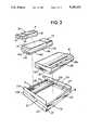
- FIG. 3is a somewhat diagrammatic exploded-type perspective view similar to FIG. 2, but illustrating the case where the standardized open frame with associated paper tray as bottom closure, is further provided with a cradle serving as an auxiliary receptacle for receiving the modular terminal assembly, and showing the modular printer assembly in a reversed orientation in comparison to FIG. 2;
- FIG. 4is a somewhat diagrammatic exploded-type perspective view similar to FIG. 3, but showing the terminal cradle at an opposite side of the open frame;
- FIG. 5is a somewhat diagrammatic perspective view of the carrying handle showing the handle as it appears when removed from the remaining parts of FIG. 1;
- FIG. 6is a somewhat diagrammatic perspective view of a portable version of the invention as actually constructed
- FIG. 7is a somewhat diagrammatic transverse sectional view of the embodiment of FIG. 6 and showing internal construction at the terminal module of the portable device;
- FIG. 8is a somewhat diagrammatic transverse sectional view of the embodiment of FIG. 6 and showing the printer case and other internal parts at a rear printer module receiving portion of the portable version of FIGS. 6 and 7, the printer cover, and printer module having been removed from the printer case to reveal the rear wall of the printer case;
- FIG. 9is a somewhat diagrammatic top plan view of the portable version of the invention, with the printer module, printer cover and instrument panel finish strip removed to show interior construction of the printer case and paper tray module;
- FIG. 10is a somewhat diagrammatic longitudinal sectional view of the portable embodiment of FIG. 6;
- FIG. 11is an enlarged somewhat diagrammatic partial longitudinal sectional view showing the printer module within the printer case, and indicating a pivoted position of the printer module in dot dash outline wherein access is provided to the paper tray bin of the paper tray module;
- FIG. 12is a somewhat diagrammatic side elevational view of an AC adapter module which may replace the foot at the left side of the portable version of FIG. 6 so as to provide for operation of the printer system of FIGS. 6-11 from commercial alternating current power;
- FIG. 13is a somewhat diagrammatic partial transverse sectional view showing the AC adapter module of FIG. 12 operatively secured with the portable embodiment of FIGS. 6-11 in place of the foot member;
- FIG. 14is a somewhat diagrammatic partial elevational view showing the frontal end of the AC adapter module of FIGS. 12 and 13;
- FIG. 15is a somewhat diagrammatic perspective view of a non-portable version of the printer system which utilizes the frame module, and other components of FIGS. 6-11, rearranged so as to be particularly suited to mounting in a delivery vehicle or the like;
- FIG. 16is a somewhat diagrammatic longitudinal sectional view of the device of FIG. 15, and showing use of a paper tray module of greater capacity than that of FIGS. 6-11;
- FIG. 17is a somewhat diagrammatic exploded perspective view showing details of the printer system of FIGS. 6-16, and showing the use of a new type of docking module with the printer system for enhanced ease of loading and accommodating the terminal configuration of the first, fifth and twenty-second figures of incorporated application U.S. Ser. No. 07/347,602 for example;
- FIG. 18is a somewhat diagrammatic exploded perspective view of the new docking module shown in FIG. 24;
- FIG. 19is a side elevational view of the docking module of FIG. 18, with portions broken away in in section, so as to reveal details of internal construction;
- FIG. 20is a diagrammatic illustration of the data communication system provided by the terminals of the incorporated U.S. patent application Ser. No. 07/347,602, and the printer systems of FIGS. 6 through 18.
- a unitary modular portable printer device 10is shown as comprising a standardized open frame module 11 having a paper tray module 12 assembled therewith as bottom closure.
- a terminal module 14 with a hinged cover 15Fitting within the open frame 11 are a terminal module 14 with a hinged cover 15, and a printer module 16 having a paper outlet slot 16A which may be selectively covered by means of a laterally shiftable cover strip 17.
- a carrying handle 18is slidably engaged with an external side of the open frame 11.
- the open frame 11is composed of four rectilinearly arranged frame elements 21-24 and a single additional frame element or crosspiece 25 subdividing the open frame to provide a terminal receptacle 26 and a printer receptacle 27.
- the terminal module 14has downward directed horizontal surfaces such as 14A and 14B at the four side thereof which are upwardly offset relative to a bottom 14C of the terminal module.
- Vertically disposed side walls such as 14D and 14Eextend from the outer perimeter of the bottom 14C to inner margins of the surfaces such as 14A and 14B.
- the terminal module 14fits into receptacle 26 with surfaces such as 14A and 14B resting on four rectilinearly arranged ledge portions such as 23A and 24A which are provided by the frame elements 21, 23, 24 and 25. These ledge portions at their inner edges confront the terminal module side walls such as 14D and 14E when the terminal module is assembled therewith.
- ledge portions such as 23A, 24A of the frame elements 21, 23, 24 and 25may be taken as principally defining terminal module receptacle 26.
- ledges such as 23A and 25A of frame elements 21, 22, 23 and 25support upwardly offset surfaces such as 16A and 16B of printer module 16, and confront side walls such as 16C and 16D, and may be taken as essentially defining printer module receptacle 27.
- the terminal module 14releasably receives the computerized terminal 30 upon opening of cover 15.
- the terminal module 14may have an interior space of size to receive terminals known as the model 121XL and model 141XL of the Norand Corporation, Cedar Rapids, Iowa.
- Such terminals 30have a display region 31, a keyboard region 32 and a battery compartment region 33, and may be used for route accounting operations, for example.
- the terminal 30may have an electrical interface at its end 35 which may comprise a 15-pin connector which mates with a mating connector within module 14 as the terminal is inserted into its module.
- a terminal 30may weigh about one kilogram including batteries, memory and communications adapter.
- the electrical interface at 35 and other constituents of terminal 30may allow the supply of data to the terminal module interface for printing by means of the printer unit within printer module 16.
- printer module 16may be of interior configuration to receive a commercially available eighty column printer which can print on three-ply fanfold paper supplied by the paper tray module 12, e.g. paper having a width between 5.0 inches and 10.0 inches.
- a commercially available eighty column printerwhich can print on three-ply fanfold paper supplied by the paper tray module 12, e.g. paper having a width between 5.0 inches and 10.0 inches.
- An example of such a printeris the Citizen MPS-20.
- Paper tray module 12may for example, for the portable device have a capacity of fifty sheets of three-ply paper. As an option for a non-portable device as in FIG. 3, a paper tray module may have a capacity of two hundred three-ply sheets.
- FIG. 2shows the frame element 21 as including upper and lower flange portions 21A and 21B which have opposed edges overhanging a central body portion 21C so as to define a guideway 37 for receiving a slider member 38, FIG. 5, integral with the carrying handle 18.
- a similar guideway 39is defined by flange portions of the frame element 23.
- the open frame 11 and paper tray 12may be identical and yet provide a non-portable subassembly 40 which may differ from portable device 10 by the absence of handle 18, and attachment of a side arm bracket 41 to the frame 11.
- the bracket 41may form a terminal cradle with a terminal module receptacle 42 receiving a terminal module 14 identical to that received by portable device 10.
- the printer module receptacle 27is identical to that of the portable device 10, so as to receive the printer module 16 in the same orientation as in FIG. 1, or reversed as in FIG. 2.
- a second terminalmay be located at 42, FIG. 3, where it may be automatically maintained in a charged condition by means of a charger connected with vehicle power.
- a lockable lift-up cover of module 14may retain a terminal 30 similarly to the way shown in a brochure number 960-382-509 of Norand Corporation which has a 1985 copyright notice and which relates to a data system for bakery distribution.
- the content of this brochureis incorporated herein by reference in its entirety by way of background information as to exemplary functioning of the computerized terminal 30 and of the illustrated printer systems.
- FIG. 4shows a non-portable printer subassembly 40' identical to subassembly 40 except that the side arm bracket 41 is mounted on the left side of the printer module receptacle 27 instead of the right side as in FIG. 3.
- the terminal module receptacle 26is shown ready to receive a second terminal module so that two terminals such as 30 may be present where desired.
- one terminal at 26may be recharged while the second terminal 30 is removed from a terminal module 14 secured in receptacle 42 for use during delivery to a retail store or the like.
- the side arm bracket 41may have a slider member 41A integral therewith which is slidably engageable in guideway 37, FIG. 3, or guideway 39, FIG. 4.
- Suitable meansmay retain the handle or terminal cradle in assembled relationship to the frame, e.g. screws or the like.
- the terminal and printer modulesmay be fixedly retained with the open frame e.g. by threaded fasteners.
- the portable printer device 10 of FIG. 1may consist essentially of open frame 11 with handle 18, tray module 12 secured to the open frame 11, terminal module 14 secured to the open frame 11, and printer module 16 secured to the open frame 11 and containing a printer unit which can be readily removable from module 16 to provide quick access to the paper tray 12.
- the terminal module 14may removably receive a computerized terminal such as 30, FIG. 2, essentially as shown in the incorporated brochure number 960-382-509 of 1985 for the case of a van-mounted printer installation or for the case of a multi-terminal charger installation (except that a manually operated latch may be substituted for a lock on the hinged cover 15).
- the terminal module for a given terminal configurationis essentially the same for portable and non-portable devices.
- the terminal moduleis field replaceable by the customer through the use of simple tools so that the customer has the option of replacing an original terminal module with one for a new terminal, e.g. a physically smaller terminal.
- a non-portable printer devicemay consist essentially of a subassembly 40 or 40' formed of the open frame 11 and paper tray 12, together with a side arm terminal cradle 41 and a printer module 16 secured to the frame 10.
- Module 16would again contain a printer unit which is readily removable so as to provide quick access to the paper tray module for the replenishing of the paper supply.
- the printer and terminal keyboardare preferably operable without removing or lifting a cover.
- the overall dimensions of each device, exclusive of parts 18 or 41,may be less than 5 1/2 inches high, 15 178 inches wide and 14 1/2 1/2 deep.
- the portable device with a self-contained chargeable battery (not shown) for the printer unitmay have a weight of less than twelve pounds excluding terminal 30. The battery when fully charged may provide for 10,000 lines of printed output.
- a DC/DC battery chargermay be an optional source of overnight trickle charging for the printer battery from a route vehicle battery, similarly to the Model NP207 briefcase printer of Norand Corporation.
- the portable and non-portable systems hereinprovide for data communication from the terminal 30 via the terminal module 14 to the printer unit associated with printer module 16.
- the printer unitmay have a pendant cable for receiving power, data and control signals.
- the length of the printer cablemay be sufficient to plug into a receptacle of the printer module prior to assembly of the printer unit with the printer module.
- the portable unitmay have an AC/DC battery charger operable from commercial alternating current power for charging the batteries of a terminal 30 which is inserted into the terminal module 14 and for charging the printer battery.
- the battery chargermay be located in extra space within the paper tray 12 along with the printer battery.
- An adjacent electric power receptaclemay releasably receive an alternating current power cord for supplying commercial alternating current power to the charger during battery charging operation.
- Rain coversmay be provided for the portable device and may be snapped on over the terminal module 14 and the printer module 16.
- strips of synthetic materials which adhere when pressed together, and known under the trademark VELCRO,may be applied to mating edges of the open frame 11 and of a top cover therefor.
- the printer module 16may be assembled in receptacle 27 in a first orientation with the front of the printer adjacent frame element 22 as shown in FIG. 2, or in a second reverse orientation with the rear of the printer adjacent frame element 22 as shown in FIG. 3.
- the terminal cradle 40may be secured at either of two opposite sides of open frame 11 as shown in FIGS. 3 and 4.
- Data communication between the terminal module 14 and the printer module 16 or preferably the printer unit thereinmay take place via optical couplers and fiber optic conduits molded into the open frame 11.
- Optical couplersmay be provided at frame elements 25 and 22, FIG. 2, to accommodate a single optical coupler of the printer unit, or the printer unit may be provided with two optical couplers in parallel each registering with a single optical coupling on the frame 11 for a respective one of two different orientations of the printer module and printer.
- a van mounting plate(not shown) may be provided with tilt adjustment so that the angle of the modular printer device may be optimized in a non-portable installation.
- operating power for the charging of the terminal and printer batteriesmay be obtained from the vehicle power system in which the modular printer device is installed.
- FIG. 6is a perspective view illustrating a commercial version of a portable modular printer device 100 in accordance with the present invention.
- the devicecomprises a standardized open frame module 111 which receives a paper tray module 112, a terminal module 114 and a printer module 116.
- a printer cover 117has a paper outlet slot 117A.
- a control panel 118may include actuating regions such as "Advance Page” actuator 118A and a "Set Top of Page” actuator 118B.
- the open frame 111may have a configuration similar to that of frame 11 of FIG. 2, and in each embodiment the frame may be of integral unitary construction and of structural plastic material (e.g. Noryl FN-215) so as to provide the desired strength and rigidity with a minimum weight of material.
- Left and right frame elements 121 and 123have upper and lower flange portions similar to flanges 21A, 21B, FIG. 2, which protectively embrace terminal module 114, printer module 116 and paper tray module 112.
- frame elements 121 and 123have central grooves which are shown as receiving an interior rib structure 130A of a foot member 130 and a base rib structure 140A of a handle member 140. Threaded fastening elements such as indicated at 141 and 142 in FIG. 8 may secure members 130 and 140 with the frame 111. As seen FIG. 6, a base 140B of handle member 140 may extend for the entire length of frame element 123 so as to completely cover the central groove therein.
- terminal module 114has an elongated recess 114A accommodating reciprocal movement of a terminal retainer bracket 150.
- a hand-held terminal corresponding to terminal 30 FIG. 2,is indicated in dash outline at 152, FIG. 7, in coupled relationship to the terminal module 114.
- the terminal 152is disengaged from the terminal module by sliding the retainer bracket 150 to the right as seen in FIG. 7, against the action of a spring means located in a bottom portion of the terminal module 114.
- the spring meansacts on the bracket 150 with sufficient force to insure interengagement of a socket of the terminal 152 with a plug type connector 154 associated with the terminal module 114.
- Connector 154is connected with the electric circuitry of the printer device 100 by means of a cable indicated at 160. As previously described, connector 154 and cable 160 provide for data communication between the terminal indicated at 152 and a printer unit associated with printer module 116.
- terminal module 114is comprised of a terminal holder base 170 of molded plastic construction (e.g. Cycolac KJW, Borg Warner)
- the base 170may be threadedly secured to bosses integral with the underlying frame elements corresponding elements 24 and 25, FIG. 2.
- the base 170is provided with a double wall configuration at its opposite longitudinal ends such that the cable 160 may extend within an enclosed chamber 172.
- paper tray module 112 of the portable device 100may be provided with a fifty sheet paper bin 180 for holding a supply of paper which is to be automatically fed into the printer mechanism.
- the paper tray 112-1 shown in FIG. 16is equipped with a larger paper bin 180-1 capable of holding 200 sheets for automatic feed into a printer mechanism.
- the larger capacity paper tray module 112-1is normally associated with a non-portable device such as shown in FIGS. 15 and 16.
- the paper tray modules 112 and 112-1may be identical except for the difference in capacity of the paper bins.
- terminal holder base 170may have an integral depressed central bottom 190 (FIG. 7) with two integral upstanding bosses 191, 192 (FIG. 9) serving to secure the ends of a tension spring indicated diagrammatically at 194.
- the bracket 150includes an integral slider piece 200 with an integral depending lug 201 about which a mid region 194A of spring 194 may extend.
- slider piece 200may have integral depending legs with outturned feet such as 211 which interengage with ledge parts such as 215 which are integral with the terminal holder base 170.
- the upper edges of the ledge parts such as 215are chamfered, e.g. over a distance of 0.040 inch at forty-five degrees, at their inner edges so that the feet such as 211 will be cammed inwardly as the sliding retainer bracket 150 is pressed downwardly during assembly with the terminal holder base 170.
- the legs 211snap into interengagement with ledges such as 215 to hold the parts in assembled relation while accommodating longitudinal sliding motion of the retainer bracket 150.
- the connector 154has an associated alignment pin 220 which engages in a receiving socket on the terminal 152 and assures reliable interengagement of the connector pins and sockets in spite of manufacturing tolerances.
- the depressed bottom 190 of the terminal holder baseprovides a clearance space 221, FIG. 9, into which the slider piece 200 moves to accommodate insertion of one end of the computer terminal 152, FIG. 7, under lip 222 of the retainer bracket 150, and to allow the opposite end of the terminal 152 to be lowered into engageable alignment with the pin 220, after which the bracket 150 is allowed to move to the left (as viewed in FIG. 7) until the terminal 152 is interengaged with connector 154 in readiness for a data transfer operation.
- the ledges such as 215had a length of about 5.4 inches, and the outturned feet such as 211 had a length of about four inches.
- the length of the slider piece 200was about 9.1 inches while its slideway including clearance space 221 was about 10.2 inches, the slider piece 200 being longitudinally shiftable over a distance of about one inch against the action of spring 194.
- the open frameis provided with four integral tabs such as 231, FIG. 10, having internally threaded sleeves for receiving screws such as 232, FIGS. 9 and 10.
- a sealing strip 240extends about the perimeter of the two openings in the frame 111 with a downturned integral edge 241 of the terminal module 114 being held in sealing relation against the seal strip 240 continuously about the perimeter of the terminal module.
- the paper tray module 180has bosses such as 250 (FIG. 8), 251 (FIG. 10) and 252 (FIGS. 8 and 10) at respective corners which receive screws such as 253, FIG. 10, threadedly engaged with the frame 111.
- the framehas integral corner tabs such as 254 (FIG. 8), 255 (FIGS. 8 and 10) and 256 (FIG. 10) with internally threaded sleeves for receiving the screws such as 253.
- the paper tray moduleincludes a pair of integral retaining fingers 261, 262 for receiving a battery pack 263 for use during portable operation.
- a printed circuit board 264, FIG. 7, occupying a left marginal region of the paper tray 112may have a plug-in type receptacle thereon adjacent finger 261, FIG. 9, for receiving input direct current operating power from the battery pack.
- control panel 118includes an apertured structural member 270A which is an integral part of a one-piece printer case 270 of plastic material (e.g. Cycolac KJW, Borg Warner)
- the caseis of generally open rectangular configuration and overlies four elements of the frame 111 (corresponding to frame elements 21, 22, 23, 25, FIG. 2).
- the case 270includes a rectangular perimeter 271, FIG. 10, which continuously sealingly engages the sealing strip 240.
- the frame 111includes an integral crosspiece 280, FIG. 10, with integral tab portions such as 281, FIG. 10, having threaded sleeves to which overlying flanges such as 282 (FIGS. 9 and 10) and 283 (FIG. 9) of the printer case 270 are secured by means of screws such as 284. Corner tabs 254 and 255, FIG. 8, of the frame 111 are threadably engaged with corner flange parts 287 (FIGS. 8-10) and 288 (FIG. 8 and 9) as indicated by screw 291, FIGS. 9 and 10.
- the printer case 270is provided with integral inwardly projecting ribs at opposite sides thereof which define printer module mounting means 301, 302, FIGS. 9 and 10.
- the purpose of mounting means 301, 302is explained in detail hereafter in reference to FIG. 11.
- each of the mounting meansincludes a vertical guide channel such as 301A connecting with an arcuate guide channel such as 301B.
- a rear wall element 270B of the printer case 270has a series of five notches leaving exposed ledges such as 311 which interengage with hook parts integral with vertical ribs such as 312, FIG. 10.
- Thisprovides for a hinged coupling of the rear wall 117B of cover 117 with the rear wall 270B of the printer case, the frontal edge of cover 117 having a series of cam hooks such as 314 which can be snapped into engagement with an edge 315 of the printer case 270.
- the cover 117When the cover 117 is opened, it can be completely removed by pulling the integral hooks of ribs 312 forwardly out of the notches 310.
- the rear wall element 270B, FIG. 10has a sealing strip 320 secured thereon which engages with a lower edge of cover wall 117B when the cover 117 is in closed position.
- the cover 117has a further sealing strip 321 which together with sealing strip 320 extends along the entire closure perimeter of the cover 117.
- a clear soft plastic strip 330may be secured in a recess 331, FIG. 6, e.g by means of adhesive at 332, FIG. 10, so that a flap 330A of strip 330 normally covers the paper outlet slot 117A while still allowing paper to be fed therefrom during printing operation.
- FIG. 11shows a printer module 350 interengaged with the printer case 270.
- the printer moduleis provided with a generally U-shaped pivot frame 351 of pressed metal which adapts various commercially available printer mechanisms such as 352 to the printer case 270.
- the pivot frame 351has upstanding lateral flanges such as 351A each of which carries a pivot shaft with a disk 355 which fits into a conforming receiving slot such as indicated at 356, FIG. 10, of the printer module mounting means 301, 302, FIG. 9.
- a limit pin 360, FIG. 11, of each pivot frame lateral flangeis of lesser diameter than disk 355 so as to be freely movable in the vertical channel 301A and in the arcuate channel 301B, FIG. 10.
- the pivot frame 351 of the printer module 350is further provided with a pair of longitudinally extending flanges such as 351B which carry rotary latch mechanisms 361.
- the latch mechanismseach include a sleeve 362 which has an extended position as indicated in dot dash outline at 362-1 and which is shiftable against the action of a compression spring 364 as the printer module pivots clockwise as shown in FIG. 11 from the inactive position 350-1 to the position shown in solid lines at 350.
- a bar-shaped lug 366moves through a conforming elongated slot such as 367 in a tab such as 288, FIG. 9.
- the pivot frame 350further includes a central curved extension 351C disposed between the longitudinal flanges 351B and providing a smooth paper guide face 370 which forms part of a paper feed path 371.
- the paper pathmay be extended as indicated at 371-1.
- FIGS. 12-14show an AC adapter module 400 which is readily applied to the portable version of FIGS. 6-11 in place of foot member 130
- the module 400is provided with internally threaded sleeves at 401-403 so as to be aligned with respective apertures such as that receiving screw 141, FIG. 8.
- the frame module of FIGS. 13 and 14may be identical to the frame module 111 of FIGS. 6-11 so that the same reference numeral has been applied in FIGS. 13 and 14, the aperture 410, FIG. 13, being covered by the foot member 130 in FIGS. 6-11.
- the adapter module 400may have a pair of flat raised parts such as 400A, FIG. 13, for resting stably on a flat surface with the handle uppermost.
- the module 400has external closure walls 411-416 and butts against frame element 121 so as to provide a first chamber 421 open only at an end 421A, and a second chamber 422 closed at both ends by walls 414 and 416.
- a power cord 430includes a coiled section 430A stored in chamber 421 and fur&her section 430B extending in chamber 422.
- An inner end portion 430C of the power cordextends from chamber 422 to a central chamber 433 and then through aperture 410, FIG. 13, in frame 111 and into the interior of the portable device.
- the AC powermay be supplied to a suitable power supply circuit within the portable device. Alternatively the power supply circuit may be located within chamber 422, for example.
- a conventional power plug 440is affixed at the outer end of the power cord and when not in use may be engaged in slots 441 in a closure wall 416A at the adjacent end of chamber 422.
- the plug 440When the power cord 430 is to be connected with commercial AC power, the plug 440 is disengaged from the slots 441 in wall 416A, and the coiled section 430A withdrawn as far as necessary from chamber 421 through the open end 421A.
- FIGS. 15 and 16show a non-portable version 500 which may be constructed primarily from the same components as the portable version of FIGS. 6-11.
- the frame module 111may be identical to frame module 111 of FIGS. 6-14 and receive the same reference numerals.
- the printer caseis identical to the case 270 of FIGS. 6-11 and has the same reference numeral applied thereto. Since the printer case 270, FIG. 16 has been reversed in its receiving space of frame 111, the frame side walls 121 and 123 are to the right and left relative to the control panel 118 which is considered to be at the front of the device.
- printer cover 117 and paper outlet slot 117Aare identical, but are of reversed orientation along with the printer module and printer case 270.
- the receptacle for the terminal module 114simply receives a cover plate 510, while in place of foot member 130, FIG. 7, the frame module 111 receives a terminal side bracket 520, which secures to the frame in the same manner as foot member 130, FIG. 8, or AC module 400, FIG. 12.
- the terminal side bracket 520receives a terminal module 114 identical to that of FIG. 7.
- Reference numerals 150, 152 and 222are applied in FIG. 15 and have been explained in relation to FIGS. 7 and 9.
- the aperture 410, FIG. 13, in the frame module 111is of a size and location to accommodate the cable 160, FIG. 7, optionally for the case of the embodiment of FIGS. 15 and 16.
- the paper tray module of FIGS. 15 and 16may correspond with the paper tray module 112 of FIGS. 7 and 8, but may be of substantially greater depth so that paper bin 180-1 of FIG. 16 may accommodate a substantially greater number of paper sheets, e.g. two hundred paper sheets instead of fifty.
- the printer module 350may be completely removed from the unit by vertically aligning limit pin 360 under disk 355, FIG. 11, and then lifting module 350 vertically so that pin 360 trave)s upwardly along channel 301a as the disk is lifted from its receiving recess 356, FIGS. 9 and 10.
- the electrical connectionsmay be of the pin and socket type so as to readily severed, and readily reestablished.
- FIG. 17is an exploded view showing anew snap lock type docking module 800 for association with the remaining parts of the modular printer system of FIGS. 6-16.
- FIG. 17shows the following parts identical to those of FIGS. 6-16:
- FIG. 18shows a somewhat diagrammatic exploded perspective view of the terminal docking module 800.
- the docking modulehas a series of spring contact fingers 801 mounted by means of printed circuit board 802.
- the spring fingersmay be arranged as shown in pending U.S. patent application Ser. No. 07/327,660 filed Mar. 23, 1989, so as to engage with the contact pads (94, FIG. 5 of incorporated U.S. patent application Ser. No. 07/347,602).
- a connector 805 and ribbon cable 806, FIG. 17,provide electrically conductive paths between the spring fingers 801 and associated paths on board 802, and printed circuit board 264, FIG. 17.
- Ribbon cable 807, FIG. 17,leads from printed circuit board 264 to the controller for the printer which is mounted at 301, FIG. 10.
- the cable 806may be a sixteen conductor ribbon cable having a length of twenty inches, and serving both for power and data input/output.
- a similar cable of greater lengthmay be used when module 800 is mounted in a vehicle remote from the printer.
- a cover member 810, FIG. 18,is secured to module base 811, and provides an overhanging lip at 812, FIG. 19, for retaining the lower end of a terminal.
- a latch part 820is mounted for pivotal movement on a latch mounting bracket 821.
- the bracket 821may have a pair of spaced flanges such as 822 with aligned openings such as 823 which mount trunnions such as 825 of the latch 820.
- a torsion spring 830acts on the latch to urge a mechanical sensor foot part 831, FIG. 19, of the latch into the space to be occupied by the upper end of a terminal such as 10 as it is pivoted downwardly into the receptacle 832 of the docking module.
- latch 820engages the terminal with mechanical sensor 831 causes the latch 820 to pivot until a latch spring 835, FIG. 19, snaps upwardly to engage a bend 836 thereof behind a cooperative ledge 837 of the latch.
- An extension 838 of the spring 835limits the upward movement of the spring and retains the bend 836 in blocking relationship to ledge 837 preventing reverse pivoting of the latch.
- the latch 820is thus locked in an angular position wherein a projection 840 thereof overlies the terminal receiving space and securely retains the terminal in receptacle 832. Even dropping of a portable printer will not cause release of the terminal from the receptacle since the latch 820 is securely locked in the retaining angular position.
- a latch release button 842is secured to latch spring 835 and may be manually depressed to depress bend 836 and disengage it from ledge 837 whereupon torsion spring 830 returns sensor foot 831 to its initial position, partly lifting the terminal out of receptacle 832.
- the latch button 842protrudes through aperture 844, FIG. 18, of a trim plate 845 so as to be accessible for manual depression to release the latch.
- the latch spring 835may be formed from a strip of type 304 stainless steel, cold rolled, 0.015 inch thick (no. 28 gauge) and 0.875 inch wide.
- the bend 836may form an angle of seventy-five degrees with the plane of the latch spring main body portion 835a, FIG. 18, so that the ledge 837 is captured at the bend 836.
- the height of bend 836 measured normal to the plane of body portion 835a, FIG. 18,may be 0.22 inch.
- Portion 835amay have a length of 1.844 inches and extension 838 may have a length of more than 0.2 inch where the overall length measured parallel to the plane of body portion 835a (FIG. 18) is 2.00 inch.
- the dimension from fixed end 835b to the screw location indicated at 850is 0.927 inch.
- the values 0.927, 2.00 and 1.844were changed to these values from former values of 0.957, 2.2125 and 1.913, respectively.
- FIG. 20is a diagrammatic illustration of data flow between the printer and the terminal for FIGS. 6-16 and 17-19.
- a secondary controller and interface means 900(e.g. a type 78C10 printer controller with interface circuitry) is indicated at the right.
- the interface circuitryaccommodates three switch selectable protocols as described in section 8.0 of APPENDIX B.
- the controller 900is programmed for operation as a secondary as described in APPENDIX C, e.g. at Section 4.4.9 Secondary State Machine, and Section 6.0 PRINTER PRESENTATION LAYER.
- the secondary controller 900when the printer finishes printing the print line or lines in a print command, returns a response with the same sequence number so that the terminal is advised as to which print lines are actually printed.
- the signals TXD, DTR, RTS, RXD and CTSmay be coupled e.g. via flexible cable 807, FIG. 17, to the printed circuit board 264.
- the signal paths on the printed circuit boardare indicated at 907, FIG. 20.
- the ribbon cable 806, FIG. 17,is indicated in FIG. 20, and leads to the 15 pin D-sub connector 164, FIG. 7, 9 and 10, or to the spring fingers such as 801, FIG. 18, a docking means such as 114, FIGS. 6, 9 and 15, or 800, FIGS. 17-19, being indicated at 908, FIG. 20.
- a primary controlleris indicated at 910, FIG. 20, and may be implemented as described in APPENDIX C.
- the primary controller 910may be part of a portable data device means 912.
- the electrical interfaceis described in Section 2.2.2.2 of APPENDIX B.
- a braided power ground strap 912, FIG. 17,may connect with the power ground terminal of connector 154, FIG. 7, 9 and 10, or to the power ground spring contact of contacts 801, FIG. 18.
- APPENDIX Bgives the product specification for a commercial version of the modular printer system. Section 6.5 of APPENDIX B describes the connector providing signals between the host and the printer controller. The electrical interface is further described in APPENDIX B in section 2.2.2.2.
- NPCPspecial communications protocol termed "NPCP” (Part B) is described in section 8.1 of APPENDIX B, and in APPENDIX C, and a complete specification for this "NPCP" protocol is given in APPENDIX D.
Landscapes
- Engineering & Computer Science (AREA)
- Physics & Mathematics (AREA)
- Theoretical Computer Science (AREA)
- Electromagnetism (AREA)
- General Physics & Mathematics (AREA)
- Toxicology (AREA)
- Artificial Intelligence (AREA)
- Computer Vision & Pattern Recognition (AREA)
- General Health & Medical Sciences (AREA)
- Health & Medical Sciences (AREA)
- General Engineering & Computer Science (AREA)
- Computer Hardware Design (AREA)
- Mechanical Engineering (AREA)
- Human Computer Interaction (AREA)
- Computing Systems (AREA)
- Automation & Control Theory (AREA)
- Accessory Devices And Overall Control Thereof (AREA)
Abstract
Description
______________________________________Element of FIG. 17 Location in FIGS. 6-16______________________________________frame 111 FIGS. 7 and 15paper tray module 112 FIG. 6121, 123 FIG. 6 frame elements foot member 130 FIG. 7handle member 140 FIG. 6141, 142 FIG. 8 fastening elements paper bin 180 FIG. 8tabs 231 FIG. 10screws 232 FIG. 10250, 251 FIG. 8 and 10 bosses screws 253 FIG. 10corner tabs 255 FIG. 8retaining261, 262 FIG. 9printed fingers circuit board 264 FIG. 7crosspiece 280 FIG. 10______________________________________
Claims (69)
Priority Applications (1)
| Application Number | Priority Date | Filing Date | Title |
|---|---|---|---|
| US07/549,298US5180232A (en) | 1988-07-08 | 1990-07-05 | Modular printer system |
Applications Claiming Priority (5)
| Application Number | Priority Date | Filing Date | Title |
|---|---|---|---|
| US21686888A | 1988-07-08 | 1988-07-08 | |
| US22719588A | 1988-08-02 | 1988-08-02 | |
| US34677189A | 1989-05-02 | 1989-05-02 | |
| US34760289A | 1989-05-03 | 1989-05-03 | |
| US07/549,298US5180232A (en) | 1988-07-08 | 1990-07-05 | Modular printer system |
Related Parent Applications (3)
| Application Number | Title | Priority Date | Filing Date |
|---|---|---|---|
| US21686888AContinuation-In-Part | 1988-07-08 | 1988-07-08 | |
| US22719588AContinuation-In-Part | 1988-07-08 | 1988-08-02 | |
| US34760289AContinuation-In-Part | 1986-08-08 | 1989-05-03 |
Publications (1)
| Publication Number | Publication Date |
|---|---|
| US5180232Atrue US5180232A (en) | 1993-01-19 |
Family
ID=27539741
Family Applications (1)
| Application Number | Title | Priority Date | Filing Date |
|---|---|---|---|
| US07/549,298Expired - LifetimeUS5180232A (en) | 1988-07-08 | 1990-07-05 | Modular printer system |
Country Status (1)
| Country | Link |
|---|---|
| US (1) | US5180232A (en) |
Cited By (32)
| Publication number | Priority date | Publication date | Assignee | Title |
|---|---|---|---|---|
| US5331580A (en)* | 1989-01-31 | 1994-07-19 | Norand Corporation | Data capture system with communicating and recharging docking apparatus, and modular printer and hand-held data terminal means cooperable therewith |
| US5600445A (en)* | 1993-03-23 | 1997-02-04 | Ricoh Company, Ltd. | Modular copying system using light wave, electric wave, or sonic wave interconnections |
| US5888087A (en)* | 1989-01-31 | 1999-03-30 | Norand Corporation | One-handed dock for a portable data collection terminal |
| US6030133A (en)* | 1996-02-29 | 2000-02-29 | Seiko Epson Corporation | Printing apparatus comprising plural printing units |
| US6126348A (en)* | 1998-04-10 | 2000-10-03 | Intermec Ip Corp. | Power supply system and assembly for a portable electronic printer |
| US20010014246A1 (en)* | 1999-10-16 | 2001-08-16 | Luciano Robert A. | Secure printer system for gaming devices |
| US6311032B1 (en) | 2000-10-11 | 2001-10-30 | Hewlett-Packard Company | Alignment device and method for aligning input/output devices with printers |
| US6428228B1 (en)* | 1999-12-02 | 2002-08-06 | Hewlett-Packard Company | Removable paper module for an orthogonal inkjet printer |
| US20030092477A1 (en)* | 1999-10-16 | 2003-05-15 | Sierra Design Group | Voucher gaming systems and methods |
| US20040032608A1 (en)* | 1999-05-25 | 2004-02-19 | Kia Silverbrook | Compact image processing system |
| FR2845943A1 (en)* | 2002-10-19 | 2004-04-23 | Denis Montagutelli | Modular printer components to construct various computer printer formats, uses three modules that can be assembled together, a thermal print mechanism, a frame and a case unit |
| US20040155102A1 (en)* | 2000-10-17 | 2004-08-12 | Mars Incorporated, A Delaware Corporation | Lockable removable cassette |
| US6857804B2 (en) | 1999-10-16 | 2005-02-22 | Sierra Design Group | Vertically mounted modular printer system |
| US20050152340A1 (en)* | 1997-09-16 | 2005-07-14 | Voit Eric A. | Network session management |
| US20060028528A1 (en)* | 2004-07-29 | 2006-02-09 | Zih Corp. | Interchangeable module for a portable printer and system for operating the same |
| US20070285698A1 (en)* | 2006-06-09 | 2007-12-13 | Wang Ynjiun P | Indicia reading apparatus having reduced trigger-to-read time |
| US20070284448A1 (en)* | 2006-06-09 | 2007-12-13 | Wang Ynjiun P | Indicia reading apparatus having image sensing and processing circuit |
| US7483417B2 (en) | 1996-04-18 | 2009-01-27 | Verizon Services Corp. | Telephony communication via varied redundant networks |
| US7513401B1 (en) | 2000-06-19 | 2009-04-07 | Bally Gaming, Inc. | Printer tear bar and presenter system |
| US7664097B2 (en) | 1996-04-18 | 2010-02-16 | Verizon Services Corp. | Telephone service via networking |
| US20100247214A1 (en)* | 2009-03-26 | 2010-09-30 | Xerox Corporation | Integrated Module |
| US7813332B1 (en) | 1997-03-19 | 2010-10-12 | Verizon Services Corp. | Voice call alternative routing through PSTN and internet networks |
| US7817619B1 (en) | 1996-12-18 | 2010-10-19 | Verizon Services Corp. | Internet long distance telephone service |
| US7830860B2 (en) | 1997-03-11 | 2010-11-09 | Verizon Services Corp. | Packet data network voice call quality monitoring |
| US7835344B1 (en) | 1997-03-19 | 2010-11-16 | Verizon Services Corp. | Transport of caller identification information through diverse communication networks |
| US8938062B2 (en) | 1995-12-11 | 2015-01-20 | Comcast Ip Holdings I, Llc | Method for accessing service resource items that are for use in a telecommunications system |
| US20150026076A1 (en)* | 2013-07-18 | 2015-01-22 | Netapp, Inc. | System and Method for Providing Customer Guidance in Deploying a Computing System |
| US9191505B2 (en) | 2009-05-28 | 2015-11-17 | Comcast Cable Communications, Llc | Stateful home phone service |
| US20170182818A1 (en)* | 2015-02-16 | 2017-06-29 | Zih Corp. | Cradle apparatus and printing device interface |
| CN108382080A (en)* | 2018-04-26 | 2018-08-10 | 湖州湖颖文具用品有限公司 | A kind of Portable cheque printer |
| US10677285B2 (en) | 2016-03-04 | 2020-06-09 | Hewlett-Packard Development Company, L.P. | Device hinges |
| US11565542B2 (en)* | 2020-06-30 | 2023-01-31 | Seiko Epson Corporation | Printing device |
Citations (35)
| Publication number | Priority date | Publication date | Assignee | Title |
|---|---|---|---|---|
| CH173434A (en)* | 1934-04-06 | 1934-11-30 | Ruf Buchhaltung A G | Typewriter case. |
| US2024622A (en)* | 1934-04-25 | 1935-12-17 | Bates Lab Inc | Writing machine |
| US2794664A (en)* | 1955-03-31 | 1957-06-04 | A L Smith Iron Company | Latches |
| US3745565A (en)* | 1971-04-29 | 1973-07-10 | Thorn Electrical Ind Ltd | Panel structure for mounting electrical components to provide front access thereto |
| US3830554A (en)* | 1973-05-31 | 1974-08-20 | Singer Co | Locking device for sewing machine cabinet support platforms |
| US3895768A (en)* | 1974-02-08 | 1975-07-22 | Harold G Scheck | Security clamp |
| US4084214A (en)* | 1976-05-13 | 1978-04-11 | Ebco Industries, Ltd. | Modular housing for electronic apparatus |
| US4208081A (en)* | 1979-01-03 | 1980-06-17 | International Business Machines Corporation | Easily reconfigurable data entry terminal |
| GB2045726A (en)* | 1979-04-03 | 1980-11-05 | Tohpre Ind Co Ltd | A recording paper holder for use with an appliance such as an electronic calculator |
| JPS5634468A (en)* | 1979-08-31 | 1981-04-06 | Seiko Epson Corp | Machine with printer |
| US4345147A (en)* | 1980-11-14 | 1982-08-17 | International Telephone And Telegraph Corporation | Vehicle mounted mobile business data handling system |
| US4403271A (en)* | 1980-07-28 | 1983-09-06 | International Business Machines Corporation | Apparatus for mounting and packaging data processing devices |
| US4458813A (en)* | 1982-01-21 | 1984-07-10 | Superscope, Inc. | Housing for a video cassette playback machine |
| DE8438263U1 (en)* | 1984-12-29 | 1985-03-28 | Kleinmann, Harald, 6500 Mainz | Housing for holding a computer and its components |
| DE8500180U1 (en)* | 1985-01-05 | 1985-05-09 | Hindermann, Manfred, 4795 Delbrück | Box or suitcase for computers |
| US4527285A (en)* | 1982-03-29 | 1985-07-02 | International Business Machines Corporation | Pluggable terminal architecture |
| GB2153237A (en)* | 1984-02-02 | 1985-08-21 | Hendry Robert Leishman | Modular diving control system |
| DE3408594A1 (en)* | 1984-03-09 | 1985-09-12 | Weidt, Karl A., 5900 Siegen | Kit for constructing a microcomputer terminal |
| JPS60198273A (en)* | 1984-03-23 | 1985-10-07 | Canon Inc | Portable-type electronic apparatus |
| FR2567304A1 (en)* | 1984-07-04 | 1986-01-10 | Hitachi Ltd | Control device for programmed processes |
| US4590943A (en)* | 1985-04-19 | 1986-05-27 | Physio-Control Corporation | System for providing power to portable defibrillator |
| US4620808A (en)* | 1984-04-09 | 1986-11-04 | Protype Corporation | Display typewriter |
| GB2175749A (en)* | 1985-04-16 | 1986-12-03 | Sharp Kk | Compact portable electronic computer |
| US4634304A (en)* | 1983-09-12 | 1987-01-06 | Tokyo Electric Co., Ltd. | Printer |
| JPS627582A (en)* | 1985-07-03 | 1987-01-14 | Casio Comput Co Ltd | Image forming device |
| US4645275A (en)* | 1984-06-28 | 1987-02-24 | Pucci Philip D | Portable carrying case and sound shield for a printer with a self-contained support stand |
| US4739316A (en)* | 1983-04-26 | 1988-04-19 | Sharp Kabushiki Kaisha | Structure of portable electronic apparatus |
| DE8801332U1 (en)* | 1988-02-03 | 1988-06-23 | Didas Computer GmbH, 8000 München | Carrying case for a data processing system |
| WO1988005573A1 (en)* | 1987-01-27 | 1988-07-28 | Woehler, Guenther | Portable communication device |
| WO1988005940A1 (en)* | 1987-01-30 | 1988-08-11 | Guillaume Janssens | Support for the combination of a microcomputer and a printer |
| US4773032A (en)* | 1984-11-20 | 1988-09-20 | Fujitsu Limited | Terminal input apparatus |
| US4790431A (en)* | 1987-03-31 | 1988-12-13 | International Computer Marketing Corporation | Carrying case for storing a computer and a printer operatively connected thereto |
| US4846924A (en)* | 1988-06-16 | 1989-07-11 | Monarch Marking Systems, Inc. | Method and apparatus for converting hand-held thermal labeler to a table top printer |
| US4881839A (en)* | 1988-06-14 | 1989-11-21 | Texas Instruments Incorporated | Portable electronic data handling/data entry system |
| US4922125A (en)* | 1988-03-17 | 1990-05-01 | International Business Machines Corporation | System cable assembly and component packaging |
- 1990
- 1990-07-05USUS07/549,298patent/US5180232A/ennot_activeExpired - Lifetime
Patent Citations (35)
| Publication number | Priority date | Publication date | Assignee | Title |
|---|---|---|---|---|
| CH173434A (en)* | 1934-04-06 | 1934-11-30 | Ruf Buchhaltung A G | Typewriter case. |
| US2024622A (en)* | 1934-04-25 | 1935-12-17 | Bates Lab Inc | Writing machine |
| US2794664A (en)* | 1955-03-31 | 1957-06-04 | A L Smith Iron Company | Latches |
| US3745565A (en)* | 1971-04-29 | 1973-07-10 | Thorn Electrical Ind Ltd | Panel structure for mounting electrical components to provide front access thereto |
| US3830554A (en)* | 1973-05-31 | 1974-08-20 | Singer Co | Locking device for sewing machine cabinet support platforms |
| US3895768A (en)* | 1974-02-08 | 1975-07-22 | Harold G Scheck | Security clamp |
| US4084214A (en)* | 1976-05-13 | 1978-04-11 | Ebco Industries, Ltd. | Modular housing for electronic apparatus |
| US4208081A (en)* | 1979-01-03 | 1980-06-17 | International Business Machines Corporation | Easily reconfigurable data entry terminal |
| GB2045726A (en)* | 1979-04-03 | 1980-11-05 | Tohpre Ind Co Ltd | A recording paper holder for use with an appliance such as an electronic calculator |
| JPS5634468A (en)* | 1979-08-31 | 1981-04-06 | Seiko Epson Corp | Machine with printer |
| US4403271A (en)* | 1980-07-28 | 1983-09-06 | International Business Machines Corporation | Apparatus for mounting and packaging data processing devices |
| US4345147A (en)* | 1980-11-14 | 1982-08-17 | International Telephone And Telegraph Corporation | Vehicle mounted mobile business data handling system |
| US4458813A (en)* | 1982-01-21 | 1984-07-10 | Superscope, Inc. | Housing for a video cassette playback machine |
| US4527285A (en)* | 1982-03-29 | 1985-07-02 | International Business Machines Corporation | Pluggable terminal architecture |
| US4739316A (en)* | 1983-04-26 | 1988-04-19 | Sharp Kabushiki Kaisha | Structure of portable electronic apparatus |
| US4634304A (en)* | 1983-09-12 | 1987-01-06 | Tokyo Electric Co., Ltd. | Printer |
| GB2153237A (en)* | 1984-02-02 | 1985-08-21 | Hendry Robert Leishman | Modular diving control system |
| DE3408594A1 (en)* | 1984-03-09 | 1985-09-12 | Weidt, Karl A., 5900 Siegen | Kit for constructing a microcomputer terminal |
| JPS60198273A (en)* | 1984-03-23 | 1985-10-07 | Canon Inc | Portable-type electronic apparatus |
| US4620808A (en)* | 1984-04-09 | 1986-11-04 | Protype Corporation | Display typewriter |
| US4645275A (en)* | 1984-06-28 | 1987-02-24 | Pucci Philip D | Portable carrying case and sound shield for a printer with a self-contained support stand |
| FR2567304A1 (en)* | 1984-07-04 | 1986-01-10 | Hitachi Ltd | Control device for programmed processes |
| US4773032A (en)* | 1984-11-20 | 1988-09-20 | Fujitsu Limited | Terminal input apparatus |
| DE8438263U1 (en)* | 1984-12-29 | 1985-03-28 | Kleinmann, Harald, 6500 Mainz | Housing for holding a computer and its components |
| DE8500180U1 (en)* | 1985-01-05 | 1985-05-09 | Hindermann, Manfred, 4795 Delbrück | Box or suitcase for computers |
| GB2175749A (en)* | 1985-04-16 | 1986-12-03 | Sharp Kk | Compact portable electronic computer |
| US4590943A (en)* | 1985-04-19 | 1986-05-27 | Physio-Control Corporation | System for providing power to portable defibrillator |
| JPS627582A (en)* | 1985-07-03 | 1987-01-14 | Casio Comput Co Ltd | Image forming device |
| WO1988005573A1 (en)* | 1987-01-27 | 1988-07-28 | Woehler, Guenther | Portable communication device |
| WO1988005940A1 (en)* | 1987-01-30 | 1988-08-11 | Guillaume Janssens | Support for the combination of a microcomputer and a printer |
| US4790431A (en)* | 1987-03-31 | 1988-12-13 | International Computer Marketing Corporation | Carrying case for storing a computer and a printer operatively connected thereto |
| DE8801332U1 (en)* | 1988-02-03 | 1988-06-23 | Didas Computer GmbH, 8000 München | Carrying case for a data processing system |
| US4922125A (en)* | 1988-03-17 | 1990-05-01 | International Business Machines Corporation | System cable assembly and component packaging |
| US4881839A (en)* | 1988-06-14 | 1989-11-21 | Texas Instruments Incorporated | Portable electronic data handling/data entry system |
| US4846924A (en)* | 1988-06-16 | 1989-07-11 | Monarch Marking Systems, Inc. | Method and apparatus for converting hand-held thermal labeler to a table top printer |
Non-Patent Citations (16)
| Title |
|---|
| "Handle used as Battery Compartment"; IBM TDB; vol. 27, No. 11, pp. 6692-6693; Apr. 1985. |
| "Keyboard Equipped w/Two Key Layouts"; IBMTDB; vol. 30, No. 7, pp. 428-429; Dec. 1987. |
| "Norand Route Commander", brochure #960-382-509 of the Norand Corp., 1985. |
| "Tray Assy for Mounting Interchangeable Electromagnetic Devices"; JAMTDB; vol. 29, No. 8, pp. 3692-3693; Jan. 1987. |
| Handle used as Battery Compartment ; IBM TDB; vol. 27, No. 11, pp. 6692 6693; Apr. 1985.* |
| Keyboard Equipped w/Two Key Layouts ; IBMTDB; vol. 30, No. 7, pp. 428 429; Dec. 1987.* |
| Norand Route Commander , brochure 960 382 509 of the Norand Corp., 1985.* |
| Norand Route Commander 40 Column Hand Held Printer Copyright 1985.* |
| Norand Route Commander 80 Column & 40 Column Van Mount Printers Copyright 1987.* |
| Norand Route Commander NP207 40 Column Briefcase Printer , Copyright 1987.* |
| Norand-Route Commander "40-Column Hand-Held Printer" Copyright 1985. |
| Norand-Route Commander "80-Column & 40-Column Van Mount Printers"-Copyright 1987. |
| Norand-Route Commander "NP207 40-Column Briefcase Printer", Copyright 1987. |
| Telxon Telxon Portable/Mountable Printer System, Form PDS IP 80 Oct. 1986.* |
| Telxon-Telxon Portable/Mountable Printer System, Form PDS IP-80 Oct. 1986. |
| Tray Assy for Mounting Interchangeable Electromagnetic Devices ; JAMTDB; vol. 29, No. 8, pp. 3692 3693; Jan. 1987.* |
Cited By (64)
| Publication number | Priority date | Publication date | Assignee | Title |
|---|---|---|---|---|
| US5888087A (en)* | 1989-01-31 | 1999-03-30 | Norand Corporation | One-handed dock for a portable data collection terminal |
| US5331580A (en)* | 1989-01-31 | 1994-07-19 | Norand Corporation | Data capture system with communicating and recharging docking apparatus, and modular printer and hand-held data terminal means cooperable therewith |
| US5600445A (en)* | 1993-03-23 | 1997-02-04 | Ricoh Company, Ltd. | Modular copying system using light wave, electric wave, or sonic wave interconnections |
| USRE40435E1 (en) | 1993-03-23 | 2008-07-15 | Ricoh Company, Ltd. | Modular copying system using light wave, electric wave, or sonic wave interconnections |
| USRE40644E1 (en)* | 1993-03-23 | 2009-03-03 | Ricoh Company, Ltd. | Modular copying system using light wave, electric wave, or sonic wave interconnections |
| US8938062B2 (en) | 1995-12-11 | 2015-01-20 | Comcast Ip Holdings I, Llc | Method for accessing service resource items that are for use in a telecommunications system |
| US6030133A (en)* | 1996-02-29 | 2000-02-29 | Seiko Epson Corporation | Printing apparatus comprising plural printing units |
| US8379531B2 (en) | 1996-04-18 | 2013-02-19 | Verizon Services Corp. | Telephony communication via varied redundant networks |
| US7664097B2 (en) | 1996-04-18 | 2010-02-16 | Verizon Services Corp. | Telephone service via networking |
| US7483417B2 (en) | 1996-04-18 | 2009-01-27 | Verizon Services Corp. | Telephony communication via varied redundant networks |
| US8553681B2 (en) | 1996-06-26 | 2013-10-08 | Verizon Services Corp. | Telephone service via packet-switched networking |
| US7817619B1 (en) | 1996-12-18 | 2010-10-19 | Verizon Services Corp. | Internet long distance telephone service |
| US7830860B2 (en) | 1997-03-11 | 2010-11-09 | Verizon Services Corp. | Packet data network voice call quality monitoring |
| US7813332B1 (en) | 1997-03-19 | 2010-10-12 | Verizon Services Corp. | Voice call alternative routing through PSTN and internet networks |
| US7835344B1 (en) | 1997-03-19 | 2010-11-16 | Verizon Services Corp. | Transport of caller identification information through diverse communication networks |
| US7948968B2 (en) | 1997-09-16 | 2011-05-24 | Verizon Communications Inc. | Network session management |
| US9215254B1 (en) | 1997-09-16 | 2015-12-15 | Verizon Patent And Licensing Inc. | Network session management for telephony over hybrid networks |
| US20050152340A1 (en)* | 1997-09-16 | 2005-07-14 | Voit Eric A. | Network session management |
| US8976782B1 (en) | 1997-09-16 | 2015-03-10 | Verizon Patent And Licensing Inc. | Network session management for telephony over hybrid networks |
| US6126348A (en)* | 1998-04-10 | 2000-10-03 | Intermec Ip Corp. | Power supply system and assembly for a portable electronic printer |
| US20040032608A1 (en)* | 1999-05-25 | 2004-02-19 | Kia Silverbrook | Compact image processing system |
| US7136183B2 (en)* | 1999-05-25 | 2006-11-14 | Silverbrook Research Pty Ltd | Compact image processing system |
| US20030092477A1 (en)* | 1999-10-16 | 2003-05-15 | Sierra Design Group | Voucher gaming systems and methods |
| US20010014246A1 (en)* | 1999-10-16 | 2001-08-16 | Luciano Robert A. | Secure printer system for gaming devices |
| US7862418B2 (en) | 1999-10-16 | 2011-01-04 | Bally Gaming, Inc. | Voucher gaming systems and methods |
| US7314324B2 (en) | 1999-10-16 | 2008-01-01 | Sierra Design Group | Vertically mounted modular printer system |
| US20050129449A1 (en)* | 1999-10-16 | 2005-06-16 | Sierra Design Group | Vertically mounted modular printer system |
| US6857804B2 (en) | 1999-10-16 | 2005-02-22 | Sierra Design Group | Vertically mounted modular printer system |
| US6814518B2 (en) | 1999-10-16 | 2004-11-09 | Sierra Design Group | Secure printer system for gaming devices |
| US6443642B1 (en)* | 1999-10-16 | 2002-09-03 | Sierra Design Group | Modular printing system |
| US6428228B1 (en)* | 1999-12-02 | 2002-08-06 | Hewlett-Packard Company | Removable paper module for an orthogonal inkjet printer |
| US7513401B1 (en) | 2000-06-19 | 2009-04-07 | Bally Gaming, Inc. | Printer tear bar and presenter system |
| US6311032B1 (en) | 2000-10-11 | 2001-10-30 | Hewlett-Packard Company | Alignment device and method for aligning input/output devices with printers |
| US20040155102A1 (en)* | 2000-10-17 | 2004-08-12 | Mars Incorporated, A Delaware Corporation | Lockable removable cassette |
| US7789214B2 (en) | 2000-10-17 | 2010-09-07 | Mei, Inc. | Stacker mechanisms and cassettes for banknotes and the like |
| US8616360B2 (en) | 2000-10-17 | 2013-12-31 | Mei, Inc. | Lockable removable cassette |
| US20100156036A1 (en)* | 2000-10-17 | 2010-06-24 | Mei, Inc. | Lockable Removable Cassette |
| US20040213620A1 (en)* | 2000-10-17 | 2004-10-28 | Mars Incorporated, A Delaware Corporation | Lockable removable cassette |
| US7481308B2 (en)* | 2000-10-17 | 2009-01-27 | Mei, Inc. | Lockable removable cassette |
| FR2845943A1 (en)* | 2002-10-19 | 2004-04-23 | Denis Montagutelli | Modular printer components to construct various computer printer formats, uses three modules that can be assembled together, a thermal print mechanism, a frame and a case unit |
| WO2004037544A1 (en)* | 2002-10-19 | 2004-05-06 | Denis Montagutelli | Modular printer |
| US20060104694A1 (en)* | 2002-10-19 | 2006-05-18 | Denis Montagutelli | Modular printer |
| US20060028528A1 (en)* | 2004-07-29 | 2006-02-09 | Zih Corp. | Interchangeable module for a portable printer and system for operating the same |
| US7740176B2 (en) | 2006-06-09 | 2010-06-22 | Hand Held Products, Inc. | Indicia reading apparatus having reduced trigger-to-read time |
| US20100289915A1 (en)* | 2006-06-09 | 2010-11-18 | Hand Held Products, Inc. | Indicia reading apparatus having image sensing and processing circuit |
| US8025232B2 (en) | 2006-06-09 | 2011-09-27 | Hand Held Products, Inc. | Indicia reading apparatus having image sensing and processing circuit |
| US20070284448A1 (en)* | 2006-06-09 | 2007-12-13 | Wang Ynjiun P | Indicia reading apparatus having image sensing and processing circuit |
| US8186595B2 (en) | 2006-06-09 | 2012-05-29 | Hand Held Products, Inc. | Indicia reading apparatus having image sensing integrated circuit |
| US8348167B2 (en) | 2006-06-09 | 2013-01-08 | Hand Held Products, Inc. | Indicia reading apparatus having image sensor array |
| US20110057039A1 (en)* | 2006-06-09 | 2011-03-10 | Wang Ynjiun P | Indicia reading apparatus having image sensing and processing circuit |
| US20070285698A1 (en)* | 2006-06-09 | 2007-12-13 | Wang Ynjiun P | Indicia reading apparatus having reduced trigger-to-read time |
| US7984855B2 (en) | 2006-06-09 | 2011-07-26 | Hand Held Products, Inc. | Indicia reading apparatus having image sensing and processing circuit |
| US8727223B2 (en) | 2006-06-09 | 2014-05-20 | Hand Held Products, Inc. | Indicia reading apparatus having image sensor array |
| US7784696B2 (en) | 2006-06-09 | 2010-08-31 | Hand Held Products, Inc. | Indicia reading apparatus having image sensing and processing circuit |
| US20100247214A1 (en)* | 2009-03-26 | 2010-09-30 | Xerox Corporation | Integrated Module |
| US8172228B2 (en) | 2009-03-26 | 2012-05-08 | Xerox Corporation | Integrated module |
| US9191505B2 (en) | 2009-05-28 | 2015-11-17 | Comcast Cable Communications, Llc | Stateful home phone service |
| US20150026076A1 (en)* | 2013-07-18 | 2015-01-22 | Netapp, Inc. | System and Method for Providing Customer Guidance in Deploying a Computing System |
| US20170182818A1 (en)* | 2015-02-16 | 2017-06-29 | Zih Corp. | Cradle apparatus and printing device interface |
| US10252554B2 (en)* | 2015-02-16 | 2019-04-09 | Zebra Technologies Corporation | Cradle apparatus and printing device interface |
| US11794488B2 (en) | 2015-02-16 | 2023-10-24 | Zebra Technologies Corporation | Cradle apparatus and printing device interface |
| US10677285B2 (en) | 2016-03-04 | 2020-06-09 | Hewlett-Packard Development Company, L.P. | Device hinges |
| CN108382080A (en)* | 2018-04-26 | 2018-08-10 | 湖州湖颖文具用品有限公司 | A kind of Portable cheque printer |
| US11565542B2 (en)* | 2020-06-30 | 2023-01-31 | Seiko Epson Corporation | Printing device |
Similar Documents
| Publication | Publication Date | Title |
|---|---|---|
| US5180232A (en) | Modular printer system | |
| US5331580A (en) | Data capture system with communicating and recharging docking apparatus, and modular printer and hand-held data terminal means cooperable therewith | |
| US5484991A (en) | Portable modular work station including printer and portable data collection terminal | |
| US6189788B1 (en) | Portable modular work station including printer and portable data collection terminal | |
| US5633782A (en) | Docking station for a portable computer with a hindged support frame and movable receptacle assembly | |
| US5617301A (en) | Compact electronic apparatus and method of assembling the same | |
| US6102721A (en) | Portable apparatus having ejector for ejecting a unit stored in the receptacle | |
| US5402311A (en) | Electronic apparatus having heat sink for cooling circuit component | |
| US6042414A (en) | Vehicle dock for portable data collection terminal | |
| KR940001693B1 (en) | Electronic apparatus system including an expansion device | |
| US6219227B1 (en) | Portable computer assembly | |
| US4851812A (en) | Portable data system | |
| US6674637B2 (en) | Portable computer equipped with add-on battery | |
| US5175671A (en) | Expanding apparatus for portable electronic apparatus | |
| EP0430252B1 (en) | Portable apparatus having detachable storage unit | |
| GB2087655A (en) | Data handling system | |
| AU672476B2 (en) | Portable electronic computer with removable disk drive | |
| HK160495A (en) | Portable computer | |
| JPH07503088A (en) | modular portable computer workstation | |
| CA1338049C (en) | Modular printer system | |
| US6999695B2 (en) | Image forming apparatus having interface terminals | |
| US6290529B1 (en) | Adapter for terminal unit | |
| EP0606111A2 (en) | Expansion card slot | |
| CA1339028C (en) | Modular printer system | |
| CN213338506U (en) | Mobile law enforcement terminal |
Legal Events
| Date | Code | Title | Description |
|---|---|---|---|
| AS | Assignment | Owner name:NORAND CORPORATION, IOWA Free format text:ASSIGNMENT OF ASSIGNORS INTEREST.;ASSIGNORS:CHADIMA, GEORGE E., JR.;SCHULTZ, DARALD R.;REEL/FRAME:006274/0608;SIGNING DATES FROM 19900821 TO 19900823 | |
| STCF | Information on status: patent grant | Free format text:PATENTED CASE | |
| CC | Certificate of correction | ||
| AS | Assignment | Owner name:NORAND CORPORATION, IOWA Free format text:RELEASE BY SECURED PARTY;ASSIGNOR:FIRST BANK NATIONAL ASSOCIATION;REEL/FRAME:007340/0095 Effective date:19930201 | |
| AS | Assignment | Owner name:NORAND CORPORATION, IOWA Free format text:SECURITY INTEREST;ASSIGNOR:FIRST NATIONAL BANK OF CHICAGO, THE;REEL/FRAME:007288/0317 Effective date:19930201 | |
| AS | Assignment | Owner name:FIRST NATIONAL BANK OF CHICAGO, THE, ILLINOIS Free format text:SECURITY INTEREST;ASSIGNOR:NORAND CORPORATION;REEL/FRAME:007795/0717 Effective date:19960126 | |
| FPAY | Fee payment | Year of fee payment:4 | |
| AS | Assignment | Owner name:NORAND CORPORATION, IOWA Free format text:RELEASE OF SECURITY INTEREST;ASSIGNOR:FIRST NATIONAL BANK OF CHICAGO, AS COLLATERAL AGENT, THE;REEL/FRAME:009479/0471 Effective date:19970225 | |
| FPAY | Fee payment | Year of fee payment:8 | |
| FEPP | Fee payment procedure | Free format text:PAYOR NUMBER ASSIGNED (ORIGINAL EVENT CODE: ASPN); ENTITY STATUS OF PATENT OWNER: LARGE ENTITY | |
| FPAY | Fee payment | Year of fee payment:12 | |
| AS | Assignment | Owner name:INTERMEC IP CORP., WASHINGTON Free format text:ASSIGNMENT OF ASSIGNORS INTEREST;ASSIGNOR:INTERMEC TECHNOLOGIES CORPORATION;REEL/FRAME:016237/0161 Effective date:19990721 Owner name:INTERMEC TECHNOLOGIES CORPORATION, WASHINGTON Free format text:MERGER;ASSIGNOR:NORAND CORPORATION;REEL/FRAME:016237/0153 Effective date:19971219 |