US5179375A - Interconnection system for an electronic cash register - Google Patents
Interconnection system for an electronic cash registerDownload PDFInfo
- Publication number
- US5179375A US5179375AUS07/563,705US56370590AUS5179375AUS 5179375 AUS5179375 AUS 5179375AUS 56370590 AUS56370590 AUS 56370590AUS 5179375 AUS5179375 AUS 5179375A
- Authority
- US
- United States
- Prior art keywords
- signals
- interface
- code
- external input
- port
- Prior art date
- Legal status (The legal status is an assumption and is not a legal conclusion. Google has not performed a legal analysis and makes no representation as to the accuracy of the status listed.)
- Expired - Fee Related
Links
Images


Classifications
- G—PHYSICS
- G07—CHECKING-DEVICES
- G07G—REGISTERING THE RECEIPT OF CASH, VALUABLES, OR TOKENS
- G07G1/00—Cash registers
- G07G1/12—Cash registers electronically operated
- G07G1/14—Systems including one or more distant stations co-operating with a central processing unit
- G—PHYSICS
- G06—COMPUTING OR CALCULATING; COUNTING
- G06Q—INFORMATION AND COMMUNICATION TECHNOLOGY [ICT] SPECIALLY ADAPTED FOR ADMINISTRATIVE, COMMERCIAL, FINANCIAL, MANAGERIAL OR SUPERVISORY PURPOSES; SYSTEMS OR METHODS SPECIALLY ADAPTED FOR ADMINISTRATIVE, COMMERCIAL, FINANCIAL, MANAGERIAL OR SUPERVISORY PURPOSES, NOT OTHERWISE PROVIDED FOR
- G06Q20/00—Payment architectures, schemes or protocols
- G06Q20/08—Payment architectures
- G06Q20/20—Point-of-sale [POS] network systems
- G06Q20/202—Interconnection or interaction of plural electronic cash registers [ECR] or to host computer, e.g. network details, transfer of information from host to ECR or from ECR to ECR
Definitions
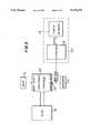
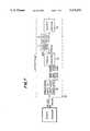
- a typical wedge of this typeis the Scanteam 2100 or 2120 decoder manufactured by Welch Allyn of Skaneateles Falls, N.Y. 13153, which is provided with a port for interfacing a wand or laser scanner, a port for interfacing magnetic slot readers, and an optional RS232 port.
- this devicehas an internal program enabling it to be configured to a particular application, in a setup procedure, to convert known outputs from an external device to desired codes for application to the terminal.
- Model 350 and 385 wedges manufactured by Symbol Technology Co. of Bohemia N.Y.are similar types of wedges.
Landscapes
- Business, Economics & Management (AREA)
- Engineering & Computer Science (AREA)
- Physics & Mathematics (AREA)
- General Physics & Mathematics (AREA)
- Accounting & Taxation (AREA)
- Computer Networks & Wireless Communication (AREA)
- Finance (AREA)
- Strategic Management (AREA)
- General Business, Economics & Management (AREA)
- Theoretical Computer Science (AREA)
- Cash Registers Or Receiving Machines (AREA)
Abstract
Description
Claims (13)
Priority Applications (1)
| Application Number | Priority Date | Filing Date | Title |
|---|---|---|---|
| US07/563,705US5179375A (en) | 1990-08-07 | 1990-08-07 | Interconnection system for an electronic cash register |
Applications Claiming Priority (1)
| Application Number | Priority Date | Filing Date | Title |
|---|---|---|---|
| US07/563,705US5179375A (en) | 1990-08-07 | 1990-08-07 | Interconnection system for an electronic cash register |
Publications (1)
| Publication Number | Publication Date |
|---|---|
| US5179375Atrue US5179375A (en) | 1993-01-12 |
Family
ID=24251565
Family Applications (1)
| Application Number | Title | Priority Date | Filing Date |
|---|---|---|---|
| US07/563,705Expired - Fee RelatedUS5179375A (en) | 1990-08-07 | 1990-08-07 | Interconnection system for an electronic cash register |
Country Status (1)
| Country | Link |
|---|---|
| US (1) | US5179375A (en) |
Cited By (25)
| Publication number | Priority date | Publication date | Assignee | Title |
|---|---|---|---|---|
| US5438186A (en)* | 1992-10-30 | 1995-08-01 | Microbilt Corporation | Multi-reader transaction terminal |
| US5514859A (en)* | 1990-10-03 | 1996-05-07 | Seagull Scientific Systems, Inc. | Power and data interface for peripheral devices |
| US5592560A (en) | 1989-05-01 | 1997-01-07 | Credit Verification Corporation | Method and system for building a database and performing marketing based upon prior shopping history |
| US5621812A (en)* | 1989-05-01 | 1997-04-15 | Credit Verification Corporation | Method and system for building a database for use with selective incentive marketing in response to customer shopping histories |
| US5642485A (en)* | 1989-05-01 | 1997-06-24 | Credit Verification Corporation | Method and system for selective incentive point-of-sale marketing in response to customer shopping histories |
| US5649114A (en)* | 1989-05-01 | 1997-07-15 | Credit Verification Corporation | Method and system for selective incentive point-of-sale marketing in response to customer shopping histories |
| US5659469A (en) | 1989-05-01 | 1997-08-19 | Credit Verification Corporation | Check transaction processing, database building and marketing method and system utilizing automatic check reading |
| US5719382A (en)* | 1996-07-22 | 1998-02-17 | Ncr Corporation | Display peripheral incorporating a wedge interface |
| US5848292A (en)* | 1996-06-19 | 1998-12-08 | Ncr Corporation | System for data transmission between a wedge microcontroller and a personal computer microcontroller by disconnecting the keyboard microcontroller and placing the same in hold state |
| US5895452A (en)* | 1993-01-26 | 1999-04-20 | Logic Controls, Inc. | Point-of-sale system |
| US6101562A (en)* | 1996-12-20 | 2000-08-08 | Inventec Corporation | Method and apparatus for inputting and recognizing characters in a PDA and transferring the recognized characters in parallel to a keyboard buffer of a PC |
| US6272529B1 (en) | 1993-01-26 | 2001-08-07 | Logic Controls, Inc. | Point-of-sale system and distributed computer network for same |
| US6292786B1 (en) | 1992-05-19 | 2001-09-18 | Incentech, Inc. | Method and system for generating incentives based on substantially real-time product purchase information |
| US6334108B1 (en) | 1989-05-01 | 2001-12-25 | Catalina Marketing International, Inc. | Method and system for selective incentive point-of-sale marketing in response to customer shopping histories |
| US6516302B1 (en) | 1999-05-26 | 2003-02-04 | Incentech, Inc. | Method and system for accumulating marginal discounts and applying an associated incentive upon achieving one of a plurality of thresholds |
| US6546441B1 (en)* | 1993-01-26 | 2003-04-08 | Logic Controls, Inc. | Point-of-sale system |
| US6684195B1 (en) | 1989-05-01 | 2004-01-27 | Catalina Marketing International, Inc. | Method and system for selective incentive point-of-sale marketing in response to customer shopping histories |
| US20040122738A1 (en)* | 1993-01-26 | 2004-06-24 | Logic Controls, Inc. | Point-of-sale system and distributed computer network for same |
| US6993498B1 (en) | 1999-07-15 | 2006-01-31 | Midnight Blue Remote Access, Llc | Point-of-sale server and method |
| US20080022017A1 (en)* | 2006-07-07 | 2008-01-24 | Logic Controls, Inc. | Hybrid industrial networked computer system |
| US20100125497A1 (en)* | 2008-12-16 | 2010-05-20 | Dale Junior Arguello | Electronic coupon distribution and redemption method for electronic devices |
| CN101615997B (en)* | 2009-07-20 | 2011-06-29 | 北京派瑞根科技开发有限公司 | Equipment for expanding network communication capability |
| US20110210170A1 (en)* | 2009-02-18 | 2011-09-01 | Arguello Dj | Digital barcode use, distribution, and redemption system for mobile devices |
| CN101615975B (en)* | 2009-07-20 | 2012-07-25 | 北京派瑞根科技开发有限公司 | Method for expanding network communication capability |
| US8700458B2 (en) | 1989-05-01 | 2014-04-15 | Catalina Marketing Corporation | System, method, and database for processing transactions |
Citations (4)
| Publication number | Priority date | Publication date | Assignee | Title |
|---|---|---|---|---|
| US4249648A (en)* | 1978-04-27 | 1981-02-10 | Keene Corporation | Token identifying system |
| US4771382A (en)* | 1981-04-30 | 1988-09-13 | Sharp Kabushiki Kaisha | Master ECR for interrogating the state and data contents of a slave ECR |
| US4887210A (en)* | 1983-06-30 | 1989-12-12 | Sharp Kabushiki Kaisha | Department level setting in an electronic cash register |
| US4887209A (en)* | 1986-11-11 | 1989-12-12 | Sharp Kabushiki Kaisha | Electronic cash register system |
- 1990
- 1990-08-07USUS07/563,705patent/US5179375A/ennot_activeExpired - Fee Related
Patent Citations (4)
| Publication number | Priority date | Publication date | Assignee | Title |
|---|---|---|---|---|
| US4249648A (en)* | 1978-04-27 | 1981-02-10 | Keene Corporation | Token identifying system |
| US4771382A (en)* | 1981-04-30 | 1988-09-13 | Sharp Kabushiki Kaisha | Master ECR for interrogating the state and data contents of a slave ECR |
| US4887210A (en)* | 1983-06-30 | 1989-12-12 | Sharp Kabushiki Kaisha | Department level setting in an electronic cash register |
| US4887209A (en)* | 1986-11-11 | 1989-12-12 | Sharp Kabushiki Kaisha | Electronic cash register system |
Cited By (43)
| Publication number | Priority date | Publication date | Assignee | Title |
|---|---|---|---|---|
| US6307958B1 (en) | 1989-05-01 | 2001-10-23 | Catalina Marketing International, Inc. | Method and system for building a database for use with selective incentive marketing in response to customer shopping histories |
| US6351735B1 (en) | 1989-05-01 | 2002-02-26 | Catalina Marketing International, Inc. | Check transaction processing, database building and marketing method and system utilizing automatic check reading |
| US8700458B2 (en) | 1989-05-01 | 2014-04-15 | Catalina Marketing Corporation | System, method, and database for processing transactions |
| US6684195B1 (en) | 1989-05-01 | 2004-01-27 | Catalina Marketing International, Inc. | Method and system for selective incentive point-of-sale marketing in response to customer shopping histories |
| US6424949B1 (en) | 1989-05-01 | 2002-07-23 | Catalina Marketing International, Inc. | Method and system for selective incentive point-of-sale marketing in response to customer shopping histories |
| US5592560A (en) | 1989-05-01 | 1997-01-07 | Credit Verification Corporation | Method and system for building a database and performing marketing based upon prior shopping history |
| US5621812A (en)* | 1989-05-01 | 1997-04-15 | Credit Verification Corporation | Method and system for building a database for use with selective incentive marketing in response to customer shopping histories |
| US5638457A (en) | 1989-05-01 | 1997-06-10 | Credit Verification Corporation | Method and system for building a database for use with selective incentive marketing in response to customer shopping histories |
| US5642485A (en)* | 1989-05-01 | 1997-06-24 | Credit Verification Corporation | Method and system for selective incentive point-of-sale marketing in response to customer shopping histories |
| US5644723A (en)* | 1989-05-01 | 1997-07-01 | Credit Verification Corporation | Method and system for selective incentive point-of-sale marketing in response to customer shopping histories |
| US5649114A (en)* | 1989-05-01 | 1997-07-15 | Credit Verification Corporation | Method and system for selective incentive point-of-sale marketing in response to customer shopping histories |
| US5659469A (en) | 1989-05-01 | 1997-08-19 | Credit Verification Corporation | Check transaction processing, database building and marketing method and system utilizing automatic check reading |
| US5675662A (en) | 1989-05-01 | 1997-10-07 | Credit Verification Corporation | Method and system for building a database for use with selective incentive marketing in response to customer shopping histories |
| US5687322A (en)* | 1989-05-01 | 1997-11-11 | Credit Verification Corporation | Method and system for selective incentive point-of-sale marketing in response to customer shopping histories |
| US6377935B1 (en) | 1989-05-01 | 2002-04-23 | Catalina Marketing International, Inc. | Method and system for selective incentive point-of-sale marketing in response to customer shopping histories |
| US6334108B1 (en) | 1989-05-01 | 2001-12-25 | Catalina Marketing International, Inc. | Method and system for selective incentive point-of-sale marketing in response to customer shopping histories |
| US5514859A (en)* | 1990-10-03 | 1996-05-07 | Seagull Scientific Systems, Inc. | Power and data interface for peripheral devices |
| US5536928A (en)* | 1990-10-03 | 1996-07-16 | Seagull Scientific Systems, Inc. | System and method for scanning bar codes |
| US6292786B1 (en) | 1992-05-19 | 2001-09-18 | Incentech, Inc. | Method and system for generating incentives based on substantially real-time product purchase information |
| US5444616A (en)* | 1992-10-30 | 1995-08-22 | Microbilt Corporation | Financial transaction systems and methods utilizing a multi-reader transaction terminal |
| US5438186A (en)* | 1992-10-30 | 1995-08-01 | Microbilt Corporation | Multi-reader transaction terminal |
| US5448047A (en)* | 1992-10-30 | 1995-09-05 | Microbilt Corporation | Card validation method using multiple cord data regions |
| US5895452A (en)* | 1993-01-26 | 1999-04-20 | Logic Controls, Inc. | Point-of-sale system |
| US7203728B2 (en) | 1993-01-26 | 2007-04-10 | Logic Controls, Inc. | Point-of-sale system and distributed computer network for same |
| US6272529B1 (en) | 1993-01-26 | 2001-08-07 | Logic Controls, Inc. | Point-of-sale system and distributed computer network for same |
| US20040122738A1 (en)* | 1993-01-26 | 2004-06-24 | Logic Controls, Inc. | Point-of-sale system and distributed computer network for same |
| US6546441B1 (en)* | 1993-01-26 | 2003-04-08 | Logic Controls, Inc. | Point-of-sale system |
| US5848292A (en)* | 1996-06-19 | 1998-12-08 | Ncr Corporation | System for data transmission between a wedge microcontroller and a personal computer microcontroller by disconnecting the keyboard microcontroller and placing the same in hold state |
| US5719382A (en)* | 1996-07-22 | 1998-02-17 | Ncr Corporation | Display peripheral incorporating a wedge interface |
| US6101562A (en)* | 1996-12-20 | 2000-08-08 | Inventec Corporation | Method and apparatus for inputting and recognizing characters in a PDA and transferring the recognized characters in parallel to a keyboard buffer of a PC |
| USRE45006E1 (en) | 1999-05-26 | 2014-07-08 | Midnight Blue Remote Access Llc | Method and system for accumulating marginal discounts and applying an associated incentive upon achieving threshold |
| US6609104B1 (en) | 1999-05-26 | 2003-08-19 | Incentech, Inc. | Method and system for accumulating marginal discounts and applying an associated incentive |
| US6516302B1 (en) | 1999-05-26 | 2003-02-04 | Incentech, Inc. | Method and system for accumulating marginal discounts and applying an associated incentive upon achieving one of a plurality of thresholds |
| US6611811B1 (en) | 1999-05-26 | 2003-08-26 | Incentech, Inc. | Method and system for accumulating marginal discounts and applying an associated incentive upon achieving threshold |
| US7464050B1 (en) | 1999-07-15 | 2008-12-09 | Incentech, Inc. | Method and system for facilitating consumer purchases |
| US6993498B1 (en) | 1999-07-15 | 2006-01-31 | Midnight Blue Remote Access, Llc | Point-of-sale server and method |
| US8712836B2 (en) | 1999-07-15 | 2014-04-29 | Midnight Blue Remote Access Llc | Point-of-sale server and method |
| US7984195B2 (en) | 2006-07-07 | 2011-07-19 | Logic Controls, Inc. | Hybrid industrial networked computer system |
| US20080022017A1 (en)* | 2006-07-07 | 2008-01-24 | Logic Controls, Inc. | Hybrid industrial networked computer system |
| US20100125497A1 (en)* | 2008-12-16 | 2010-05-20 | Dale Junior Arguello | Electronic coupon distribution and redemption method for electronic devices |
| US20110210170A1 (en)* | 2009-02-18 | 2011-09-01 | Arguello Dj | Digital barcode use, distribution, and redemption system for mobile devices |
| CN101615997B (en)* | 2009-07-20 | 2011-06-29 | 北京派瑞根科技开发有限公司 | Equipment for expanding network communication capability |
| CN101615975B (en)* | 2009-07-20 | 2012-07-25 | 北京派瑞根科技开发有限公司 | Method for expanding network communication capability |
Similar Documents
| Publication | Publication Date | Title |
|---|---|---|
| US5179375A (en) | Interconnection system for an electronic cash register | |
| US4894522A (en) | Interface apparatus | |
| US5253345A (en) | Point of sale register system | |
| US4866257A (en) | Bar code scanner and method | |
| USRE37635E1 (en) | System for enabling decoding of bar code and other symbols with a digital microcomputer connected via the input/output port thereof to the scanner | |
| WO1987000322A1 (en) | Checkout control system | |
| EP0390162A2 (en) | An apparatus for reading a bar code | |
| US5767500A (en) | Automatic identification of hardware | |
| US4710869A (en) | Key input data emulation system | |
| US5719382A (en) | Display peripheral incorporating a wedge interface | |
| US5179270A (en) | Scanner system interface | |
| JPS63284690A (en) | Reader for card-shaped material | |
| US5629511A (en) | Bar code scanner and scanning system for various types of operations | |
| JPH0120793B2 (en) | ||
| JPS5916034A (en) | Input device coupling system | |
| JPH06175764A (en) | Data input processing method and system | |
| JPH03164884A (en) | Handy type bar code scanner | |
| KR970002110B1 (en) | Keyboard Accessory for Computer Shorthand | |
| BG61355B1 (en) | Cash register | |
| JPH0210964B2 (en) | ||
| SU467349A1 (en) | Device for remote data processing | |
| JPS5850036A (en) | Data generating device | |
| JPS62297992A (en) | Electronic cash register | |
| SU1119057A1 (en) | Training system for radiotelegraph operator | |
| JP2762723B2 (en) | Barcode reader |
Legal Events
| Date | Code | Title | Description |
|---|---|---|---|
| AS | Assignment | Owner name:SORICON CORPORATION, COLORADO Free format text:ASSIGNMENT OF ASSIGNORS INTEREST.;ASSIGNOR:PIERSON, RANDALL M.;REEL/FRAME:005421/0482 Effective date:19900802 Owner name:SORICON CORPORATION, COLORADO Free format text:ASSIGNMENT OF ASSIGNORS INTEREST.;ASSIGNOR:DICK, DONALD E.;REEL/FRAME:005421/0480 Effective date:19900802 Owner name:SORICON CORPORATION, COLORADO Free format text:ASSIGNMENT OF ASSIGNORS INTEREST.;ASSIGNOR:ASSON, DAVID A.;REEL/FRAME:005421/0484 Effective date:19900802 Owner name:SORICON CORPORATION, COLORADO Free format text:ASSIGNMENT OF ASSIGNORS INTEREST.;ASSIGNOR:JEWETT, MARK A.;REEL/FRAME:005421/0486 Effective date:19900802 | |
| AS | Assignment | Owner name:BJERKE, RANDAL, COLORADO Free format text:SECURITY INTEREST;ASSIGNOR:SORICON CORPORATION A CORP. OF DELAWARE;REEL/FRAME:005833/0117 Effective date:19910703 | |
| AS | Assignment | Owner name:GUNTHER FAMILY TRUST, THE DATED AUGUST 24, 1989, Free format text:SECURITY INTEREST;ASSIGNOR:SORICON CORPORATION, A CORPORATION OF DE;REEL/FRAME:005906/0001 Effective date:19910916 Owner name:NICOLL, NEVILLE AND CARRIE W., COLORADO Free format text:SECURITY INTEREST;ASSIGNOR:SORICON CORPORATION, A CORPORATION OF DE;REEL/FRAME:005906/0001 Effective date:19910916 Owner name:MANCUSO FAMILY REVOCABLE TRUST, CALIFORNIA Free format text:SECURITY INTEREST;ASSIGNOR:SORICON CORPORATION, A CORPORATION OF DE;REEL/FRAME:005906/0001 Effective date:19910916 Owner name:SCRAGGY NECK INVESTORS, L.P. BOSTON CORPORATE FIN Free format text:SECURITY INTEREST;ASSIGNOR:SORICON CORPORATION, A CORPORATION OF DE;REEL/FRAME:005906/0001 Effective date:19910916 Owner name:ASHLEY, AL, CALIFORNIA Free format text:SECURITY INTEREST;ASSIGNOR:SORICON CORPORATION, A CORPORATION OF DE;REEL/FRAME:005906/0001 Effective date:19910916 Owner name:BJERKE, RANDAL, COLORADO Free format text:SECURITY INTEREST;ASSIGNOR:SORICON CORPORATION, A CORPORATION OF DE;REEL/FRAME:005906/0001 Effective date:19910916 Owner name:BETH BURNAM TRUST NO. 2, CALIFORNIA Free format text:SECURITY INTEREST;ASSIGNOR:SORICON CORPORATION, A CORPORATION OF DE;REEL/FRAME:005906/0001 Effective date:19910916 Owner name:ALMO PROPERTIES, CALIFORNIA Free format text:SECURITY INTEREST;ASSIGNOR:SORICON CORPORATION, A CORPORATION OF DE;REEL/FRAME:005906/0001 Effective date:19910916 Owner name:SPOTSWOOD, CHARLES A., MASSACHUSETTS Free format text:SECURITY INTEREST;ASSIGNOR:SORICON CORPORATION, A CORPORATION OF DE;REEL/FRAME:005906/0001 Effective date:19910916 Owner name:BRONSTEIN TRUST, THE, CALIFORNIA Free format text:SECURITY INTEREST;ASSIGNOR:SORICON CORPORATION, A CORPORATION OF DE;REEL/FRAME:005906/0001 Effective date:19910916 Owner name:CARPENTER, RICHARD, CALIFORNIA Free format text:SECURITY INTEREST;ASSIGNOR:SORICON CORPORATION, A CORPORATION OF DE;REEL/FRAME:005906/0001 Effective date:19910916 Owner name:BARWELL INC., COLORADO Free format text:SECURITY INTEREST;ASSIGNOR:SORICON CORPORATION, A CORPORATION OF DE;REEL/FRAME:005906/0001 Effective date:19910916 Owner name:TRIUMPH CAPITAL GROUP, INC. PROFIT SHARING RETIR Free format text:SECURITY INTEREST;ASSIGNOR:SORICON CORPORATION, A CORPORATION OF DE;REEL/FRAME:005906/0001 Effective date:19910916 Owner name:GLIKBARG, BILL, CALIFORNIA Free format text:SECURITY INTEREST;ASSIGNOR:SORICON CORPORATION, A CORPORATION OF DE;REEL/FRAME:005906/0001 Effective date:19910916 Owner name:SORICON CORPORATION Free format text:RELEASED BY SECURED PARTY;ASSIGNOR:BJERKE, RANDAL;REEL/FRAME:005856/0261 Effective date:19910912 Owner name:FIDES, SWITZERLAND Free format text:SECURITY INTEREST;ASSIGNOR:SORICON CORPORATION, A CORPORATION OF DE;REEL/FRAME:005906/0001 Effective date:19910916 Owner name:WOLFEN, WERNER F., ESQ., CALIFORNIA Free format text:SECURITY INTEREST;ASSIGNOR:SORICON CORPORATION, A CORPORATION OF DE;REEL/FRAME:005906/0001 Effective date:19910916 Owner name:ASHLEY, TED, CALIFORNIA Free format text:SECURITY INTEREST;ASSIGNOR:SORICON CORPORATION, A CORPORATION OF DE;REEL/FRAME:005906/0001 Effective date:19910916 Owner name:OSTIN, MORRIS, CALIFORNIA Free format text:SECURITY INTEREST;ASSIGNOR:SORICON CORPORATION, A CORPORATION OF DE;REEL/FRAME:005906/0001 Effective date:19910916 Owner name:BRUCE BURNAM TRUST NO. 2, CALIFORNIA Free format text:SECURITY INTEREST;ASSIGNOR:SORICON CORPORATION, A CORPORATION OF DE;REEL/FRAME:005906/0001 Effective date:19910916 Owner name:OSTROW FAMILY TRUST, THE, CALIFORNIA Free format text:SECURITY INTEREST;ASSIGNOR:SORICON CORPORATION, A CORPORATION OF DE;REEL/FRAME:005906/0001 Effective date:19910916 Owner name:SAINT JAMES CORPORATE SERVICE LTD., COLORADO Free format text:SECURITY INTEREST;ASSIGNOR:SORICON CORPORATION, A CORPORATION OF DE;REEL/FRAME:005906/0001 Effective date:19910916 | |
| REMI | Maintenance fee reminder mailed | ||
| AS | Assignment | Owner name:SILICON VALLEY BANK, CALIFORNIA Free format text:SECURITY INTEREST;ASSIGNOR:INTERNATIONAL VERIFACT, INC. ("U.S.");REEL/FRAME:008503/0486 Effective date:19960930 | |
| LAPS | Lapse for failure to pay maintenance fees | ||
| FP | Lapsed due to failure to pay maintenance fee | Effective date:19970115 | |
| AS | Assignment | Owner name:INTERNATIONAL VERIFACT, INC., GEORGIA Free format text:RELEASE BY SECURED PARTY;ASSIGNOR:SILICON VALLEY BANK;REEL/FRAME:016593/0949 Effective date:20050511 | |
| STCH | Information on status: patent discontinuation | Free format text:PATENT EXPIRED DUE TO NONPAYMENT OF MAINTENANCE FEES UNDER 37 CFR 1.362 |