US5179262A - Manufacture of ophthalmic lenses by excimer laser - Google Patents
Manufacture of ophthalmic lenses by excimer laserDownload PDFInfo
- Publication number
- US5179262A US5179262AUS07/730,684US73068491AUS5179262AUS 5179262 AUS5179262 AUS 5179262AUS 73068491 AUS73068491 AUS 73068491AUS 5179262 AUS5179262 AUS 5179262A
- Authority
- US
- United States
- Prior art keywords
- mask
- workpiece
- laser
- laser energy
- pattern
- Prior art date
- Legal status (The legal status is an assumption and is not a legal conclusion. Google has not performed a legal analysis and makes no representation as to the accuracy of the status listed.)
- Expired - Fee Related
Links
Images

Classifications
- B—PERFORMING OPERATIONS; TRANSPORTING
- B23—MACHINE TOOLS; METAL-WORKING NOT OTHERWISE PROVIDED FOR
- B23K—SOLDERING OR UNSOLDERING; WELDING; CLADDING OR PLATING BY SOLDERING OR WELDING; CUTTING BY APPLYING HEAT LOCALLY, e.g. FLAME CUTTING; WORKING BY LASER BEAM
- B23K26/00—Working by laser beam, e.g. welding, cutting or boring
- B23K26/02—Positioning or observing the workpiece, e.g. with respect to the point of impact; Aligning, aiming or focusing the laser beam
- B23K26/06—Shaping the laser beam, e.g. by masks or multi-focusing
- B23K26/064—Shaping the laser beam, e.g. by masks or multi-focusing by means of optical elements, e.g. lenses, mirrors or prisms
- B23K26/066—Shaping the laser beam, e.g. by masks or multi-focusing by means of optical elements, e.g. lenses, mirrors or prisms by using masks
- B—PERFORMING OPERATIONS; TRANSPORTING
- B29—WORKING OF PLASTICS; WORKING OF SUBSTANCES IN A PLASTIC STATE IN GENERAL
- B29C—SHAPING OR JOINING OF PLASTICS; SHAPING OF MATERIAL IN A PLASTIC STATE, NOT OTHERWISE PROVIDED FOR; AFTER-TREATMENT OF THE SHAPED PRODUCTS, e.g. REPAIRING
- B29C59/00—Surface shaping of articles, e.g. embossing; Apparatus therefor
- B29C59/16—Surface shaping of articles, e.g. embossing; Apparatus therefor by wave energy or particle radiation, e.g. infrared heating
- B—PERFORMING OPERATIONS; TRANSPORTING
- B29—WORKING OF PLASTICS; WORKING OF SUBSTANCES IN A PLASTIC STATE IN GENERAL
- B29D—PRODUCING PARTICULAR ARTICLES FROM PLASTICS OR FROM SUBSTANCES IN A PLASTIC STATE
- B29D11/00—Producing optical elements, e.g. lenses or prisms
- B29D11/00932—Combined cutting and grinding thereof
- C—CHEMISTRY; METALLURGY
- C03—GLASS; MINERAL OR SLAG WOOL
- C03B—MANUFACTURE, SHAPING, OR SUPPLEMENTARY PROCESSES
- C03B33/00—Severing cooled glass
- C03B33/02—Cutting or splitting sheet glass or ribbons; Apparatus or machines therefor
- C03B33/04—Cutting or splitting in curves, especially for making spectacle lenses
- C—CHEMISTRY; METALLURGY
- C03—GLASS; MINERAL OR SLAG WOOL
- C03B—MANUFACTURE, SHAPING, OR SUPPLEMENTARY PROCESSES
- C03B33/00—Severing cooled glass
- C03B33/08—Severing cooled glass by fusing, i.e. by melting through the glass
- C03B33/082—Severing cooled glass by fusing, i.e. by melting through the glass using a focussed radiation beam, e.g. laser
- A—HUMAN NECESSITIES
- A61—MEDICAL OR VETERINARY SCIENCE; HYGIENE
- A61F—FILTERS IMPLANTABLE INTO BLOOD VESSELS; PROSTHESES; DEVICES PROVIDING PATENCY TO, OR PREVENTING COLLAPSING OF, TUBULAR STRUCTURES OF THE BODY, e.g. STENTS; ORTHOPAEDIC, NURSING OR CONTRACEPTIVE DEVICES; FOMENTATION; TREATMENT OR PROTECTION OF EYES OR EARS; BANDAGES, DRESSINGS OR ABSORBENT PADS; FIRST-AID KITS
- A61F2/00—Filters implantable into blood vessels; Prostheses, i.e. artificial substitutes or replacements for parts of the body; Appliances for connecting them with the body; Devices providing patency to, or preventing collapsing of, tubular structures of the body, e.g. stents
- A61F2/02—Prostheses implantable into the body
- A61F2/14—Eye parts, e.g. lenses or corneal implants; Artificial eyes
- A61F2/16—Intraocular lenses
- B—PERFORMING OPERATIONS; TRANSPORTING
- B23—MACHINE TOOLS; METAL-WORKING NOT OTHERWISE PROVIDED FOR
- B23K—SOLDERING OR UNSOLDERING; WELDING; CLADDING OR PLATING BY SOLDERING OR WELDING; CUTTING BY APPLYING HEAT LOCALLY, e.g. FLAME CUTTING; WORKING BY LASER BEAM
- B23K2103/00—Materials to be soldered, welded or cut
- B23K2103/30—Organic material
- B23K2103/42—Plastics
- B—PERFORMING OPERATIONS; TRANSPORTING
- B23—MACHINE TOOLS; METAL-WORKING NOT OTHERWISE PROVIDED FOR
- B23K—SOLDERING OR UNSOLDERING; WELDING; CLADDING OR PLATING BY SOLDERING OR WELDING; CUTTING BY APPLYING HEAT LOCALLY, e.g. FLAME CUTTING; WORKING BY LASER BEAM
- B23K2103/00—Materials to be soldered, welded or cut
- B23K2103/50—Inorganic material, e.g. metals, not provided for in B23K2103/02 – B23K2103/26
- B—PERFORMING OPERATIONS; TRANSPORTING
- B29—WORKING OF PLASTICS; WORKING OF SUBSTANCES IN A PLASTIC STATE IN GENERAL
- B29C—SHAPING OR JOINING OF PLASTICS; SHAPING OF MATERIAL IN A PLASTIC STATE, NOT OTHERWISE PROVIDED FOR; AFTER-TREATMENT OF THE SHAPED PRODUCTS, e.g. REPAIRING
- B29C35/00—Heating, cooling or curing, e.g. crosslinking or vulcanising; Apparatus therefor
- B29C35/02—Heating or curing, e.g. crosslinking or vulcanizing during moulding, e.g. in a mould
- B29C35/08—Heating or curing, e.g. crosslinking or vulcanizing during moulding, e.g. in a mould by wave energy or particle radiation
- B29C35/0805—Heating or curing, e.g. crosslinking or vulcanizing during moulding, e.g. in a mould by wave energy or particle radiation using electromagnetic radiation
- B29C2035/0838—Heating or curing, e.g. crosslinking or vulcanizing during moulding, e.g. in a mould by wave energy or particle radiation using electromagnetic radiation using laser
- B—PERFORMING OPERATIONS; TRANSPORTING
- B29—WORKING OF PLASTICS; WORKING OF SUBSTANCES IN A PLASTIC STATE IN GENERAL
- B29C—SHAPING OR JOINING OF PLASTICS; SHAPING OF MATERIAL IN A PLASTIC STATE, NOT OTHERWISE PROVIDED FOR; AFTER-TREATMENT OF THE SHAPED PRODUCTS, e.g. REPAIRING
- B29C2791/00—Shaping characteristics in general
- B29C2791/004—Shaping under special conditions
- B29C2791/009—Using laser
- B—PERFORMING OPERATIONS; TRANSPORTING
- B29—WORKING OF PLASTICS; WORKING OF SUBSTANCES IN A PLASTIC STATE IN GENERAL
- B29L—INDEXING SCHEME ASSOCIATED WITH SUBCLASS B29C, RELATING TO PARTICULAR ARTICLES
- B29L2011/00—Optical elements, e.g. lenses, prisms
- B29L2011/0016—Lenses
Definitions
- the inventionrelates generally to the manufacture of ophthalmic lenses such as contact, corneal implant, and intraocular lenses, and other small plastic or glass objects of similar shape, and more particularly to a method of making such lenses or objects with a high degree of precision at low cost by using an excimer laser.
- Ophthalmic lensesare normally manufactured by a mechanical process in which a block of polymehthylmethacrylate (PMMA) is machined while being adhesively held on a support.
- PMMApolymehthylmethacrylate
- the workpiecemust be cut out from a blank to form, for example, an integral optic and haptic.
- the surface of the workpiecemust be machined to the desired optical specifications, which may include convexities or concavities of varying radii at different points on the surface of the lens, and the edges of the workpiece must be radiused or rounded.
- the edge rounding stepalone typically required 7-14 days of gemstone tumbling, and precision was hard to accomplish in all of the steps.
- the present inventionprovides a method of fabricating ophthalmic lenses or similar small objects quickly and accurately by using a laser, and particularly an excimer laser, to cut, surface-model, and bevel a workpiece which is preferably made of PMMA but may, for appropriate purposes, be made of other plastics or of glass.
- a laserand particularly an excimer laser
- the type and tuning of the laseris dependent upon the material of the blank.
- the workpieceis first cut to shape by shining a laser beam through a mask outlining the form of the cut required to shape (in the case of an ophthalmic lens) the optic and haptic.
- a laser beamthrough a mask outlining the form of the cut required to shape (in the case of an ophthalmic lens) the optic and haptic.
- Considerable precisioncan be obtained in this step by expanding the laser beam in front of the mask and then reducing it beyond the mask to provide fine detail from a relatively large mask.
- the depth of the cutcan be controlled by the number and energy of the pulses.
- the surface modeling of the lensis next achieved by masking a laser beam in such a way that its energy distribution varies across the surface of the workpiece so as to ablate it to differing degrees at different points of the surface.
- Thiscan be achieved by using a mask of varying opacity or a semi-transparent mirror with a coating of varying thickness at different points on the surface.
- This stepif desired, may be performed before the cutting step.
- a laser beamis masked and focused generally into the form of a hollow cone whose tip is the focal point of the beam.
- two bevel cutsare made along the perimeter of the upper and lower surfaces, respectively, of the workpiece.
- these bevel cutsform an approximation of a rounded edge which is further softened by the slight melting of the workpiece material produced by the heat generated by the laser during cutting.
- the methodis modified in order to alleviate two concerns.
- One concernis that shining or projecting the laser beam through the mask toward the workpiece can be accompanied by some diffraction that may result in some distortion at the workpiece that can degrade resolution.
- Another concernis that mask size may have to approximate workpiece size and the laser beam may have to be expanded to cover the entire mask and the workpiece surface.
- a lens of one or more optical elements disposed intermediate the mask and the workpieceimages the mask (i.e., the pattern on the mask) onto the workpiece.
- the maski.e., the pattern on the mask
- a method of making small objects from a blank of ablatable materialincludes at least one of the steps of (1) cutting a workpiece from the blank by exposing the blank to laser light in the outline of said workpiece without focusing the laser light at the workpiece, (2) exposing the surface of said workpiece to laser light through a mask having areas transmitting said light in varying degrees, and (3) shaping the edges of said workpiece by exposing them to an inclined beam of laser light, that step being performed so that it includes imaging the outline or pattern on the blank to achieve the advantages described above.
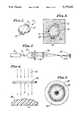
- FIG. 1is a perspective view of an intraocular lens to be manufactured by the method of this invention
- FIG. 2is a schematic diagram of a laser optic used in the cutting step of the invention
- FIG. 3a plan view of the mask used in the cutting step
- FIG. 4is a schematic diagram illustrating the surface modeling step of this invention.
- FIG. 5is a plan view of the mask used in the surface modeling step
- FIG. 6is a schematic diagram illustrating the edge beveling step of this invention.
- FIG. 7is a plan view of the mask used in the beveling step
- FIG. 8is a fragmentary detail section of the workpiece after the first beveling step.
- FIG. 9is a fragmentary detail section of the workpiece after the second beveling step.
- the method of this inventionis carried out with an excimer laser, that is a laser operating in the high ultraviolet wavelengths.
- An argon-fluoride laser operating at a wavelength of 193 nm in 250 millijoule pulsesis preferred, but broadly any ultraviolet wavelength substantially absorbed by the material of the workpiece may be used.
- the choice of the laseris dictated by its ability to break up the large molecules of the workpiece material (as in the case of plastic) or to melt the material (as in the case of glass) so that the material will ablate.
- FIG. 1shows a typical intraocular lens which may be produced by the method of this invention.
- the workpiece 10has an optic 12 which forms the actual lens, and a haptic 14 by which the lens is anchored in the patient's eye.
- polypropyleneis usually used for the haptic 14
- PMMAis used for the optic 12.
- both the optic 12 and the haptic 14may be formed of PMMA, and in the process of this invention this is preferable because the entire workpiece can be cut as a single piece.
- other ultraviolet-absorbing materials than PMMAe.g. silicone
- FIG. 2shows an arrangement useful in cutting the workpiece 10 from a block of PMMA.
- An excimer laser 16emits a beam 18 of coherent ultraviolet light. Because the diameter of beam 18 is fairly small, a conventional laser beam expander 20 is used to expand the beam 18 to a diameter of several centimeters.
- a mask 22 best shown in FIG. 3is formed integrally with the beam expander 20 or placed into the path of the expanded beam 18 to allow only a narrow strip of light in the shape of the outline 24 of the workpiece 10 to pass through the mask 22.
- a beam converger or focusing optic 26is used to project a reduced image of the outline 24 onto the PMMA block 28. Repeated pulses of the laser 16 will ablate the material of the block 28 until the profiled lens or workpiece 10 is very precisely cut out of the block 28. The precision of the cut is enhanced (and the power density of the beam increased) by the use of a relatively large mask 22 and a substantial reduction of the mask image on the block 28.
- the focusing optic 26(which in this embodiment is a biconvex optical element) can include a lens of one or more elements configured according to known techniques to image the outline 24 on the block 28.
- the step of cutting a workpiece from said blankincludes imaging the outline of said workpiece on said blank. This results in the beam having a focal point 26a intermediate the focusing optic 26 and the block 28 and, preferably, it is done so that the beam expander 20 is not needed and can be omitted.
- the workpiece 10After being cut out from the block 28, the workpiece 10 is placed into the path of an excimer laser beam 30 (FIG. 4) which has a uniform energy distribution across its area.
- a mask 32is interposed between the workpiece 10 and the beam 32.
- the mask 32has different degrees of transparency at different points on the mask 32.
- the mask 32may have a coating of variable or non-uniform transmission characteristics, or it may be a neutral density filter (such as a polarizing or haze filter) with non-uniform transmission characteristics.
- the mask 32transmits a large amount of beam energy in the areas 34 corresponding to desired depressions in the workpiece 10, and a small amount in the areas 36 corresponding to desired protrusions in the workpiece 10.
- An imaging optic arrangement 32a(FIG. 4) can be located intermediate the mask 32 and the workpiece 10 in order to image the mask 32 (i.e., the pattern on the mask) on the workpiece 10.
- the step of exposing the surface of said workpiece to laser lightincludes imaging the mask on said workpiece.
- Such an imaging optic arrangement 32aincludes a lens of one or more elements configured according to known techniques to have a focal point 32b intermediate the imaging optic arrangement 32a and the workpiece 10 in order to image the mask 32 (i.e., the pattern on the mask 32) on the workpiece 10, and imaging in this way achieves the advantages previously mentioned.
- the mask 32can be combined with the mask 22 to conduct shaping and cutting simultaneously.
- the mask 32may take the form of a semi-transparent mirror with a reflective coating whose thickness varies along its surface. In that embodiment, the laser energy not used for ablation is reflected away from the workpiece.
- the workpieceAfter the shaping or modeling step of FIGS. 4 and 5, the workpiece is fully formed but has sharp vertical edges which are not suitable for intraocular use.
- the edges of the workpiecewere radiused or rounded by gemstone tumbling for 7-14 days, but besides being time-consuming, this prior art method often defeated the carefully achieved precision of the workpiece.
- an excimer laser beam 40(FIG. 6) is expanded by a beam expander or (preferably) by a pair of curved mirrors 42 and 44.
- a beam expanderor (preferably) by a pair of curved mirrors 42 and 44.
- the use of reflective rather than refractive beam expanding opticsis preferred because it permits higher power transfer with smaller optics while avoiding damage to the optics.
- the expanded beam 46is conducted through a mask 48 best shown in FIG. 7 to a focusing lens 50.
- a beam generally in the form of a hollow coneis produced, with the tip of the cone being the focal point 52.
- the beveling of one sidecan be achieved during the cutting operation to expedite the overall process.
- the workpiece 10is first positioned below the focal point 52 at 54, and the laser is turned on.
- the conical shape of the beamwill produce a bevel 56 (FIG. 8) on the edges of the workpiece 10, the focusing lens 50 being configured to image the mask 48 on the workpiece 10.
- the ends of the bevel 56are slightly rounded at 58 and 60 by the small amount of heat which is produced during the ablation of workpiece material which forms the bevel 56.
- the bevels 56 and 64 and their rounded extremitiesprovide a sufficient approximation of a rounded edge for the workpiece 10 to make it suitable for implantation in a patient's eye without danger of irritation.
- a very narrow laser beammay be moved around the periphery of the workpiece in the cutting and beveling steps, rather than cutting or beveling the entire periphery at once, or a mask may be scanned rather than being exposed all at once.
Landscapes
- Engineering & Computer Science (AREA)
- Chemical & Material Sciences (AREA)
- Physics & Mathematics (AREA)
- Optics & Photonics (AREA)
- Health & Medical Sciences (AREA)
- Mechanical Engineering (AREA)
- Toxicology (AREA)
- Materials Engineering (AREA)
- Organic Chemistry (AREA)
- Plasma & Fusion (AREA)
- Manufacturing & Machinery (AREA)
- Ophthalmology & Optometry (AREA)
- Laser Beam Processing (AREA)
- Prostheses (AREA)
Abstract
Description
Claims (25)
Priority Applications (1)
| Application Number | Priority Date | Filing Date | Title |
|---|---|---|---|
| US07/730,684US5179262A (en) | 1986-10-14 | 1991-07-16 | Manufacture of ophthalmic lenses by excimer laser |
Applications Claiming Priority (3)
| Application Number | Priority Date | Filing Date | Title |
|---|---|---|---|
| US06/919,206US4842782A (en) | 1986-10-14 | 1986-10-14 | Manufacture of ophthalmic lenses by excimer laser |
| US07/323,493US5053171A (en) | 1986-10-14 | 1989-03-14 | Manufacture of ophthalmic lenses by excimer laser |
| US07/730,684US5179262A (en) | 1986-10-14 | 1991-07-16 | Manufacture of ophthalmic lenses by excimer laser |
Related Parent Applications (1)
| Application Number | Title | Priority Date | Filing Date |
|---|---|---|---|
| US07/323,493DivisionUS5053171A (en) | 1986-10-14 | 1989-03-14 | Manufacture of ophthalmic lenses by excimer laser |
Publications (1)
| Publication Number | Publication Date |
|---|---|
| US5179262Atrue US5179262A (en) | 1993-01-12 |
Family
ID=27406279
Family Applications (1)
| Application Number | Title | Priority Date | Filing Date |
|---|---|---|---|
| US07/730,684Expired - Fee RelatedUS5179262A (en) | 1986-10-14 | 1991-07-16 | Manufacture of ophthalmic lenses by excimer laser |
Country Status (1)
| Country | Link |
|---|---|
| US (1) | US5179262A (en) |
Cited By (13)
| Publication number | Priority date | Publication date | Assignee | Title |
|---|---|---|---|---|
| US5504302A (en)* | 1992-10-15 | 1996-04-02 | Joachim Hentze | Method and device for the production of optical lenses or the like |
| DE19701807A1 (en)* | 1997-01-21 | 1998-07-23 | Technomed Ges Fuer Med Und Med | Method of manufacturing artificial lens |
| DE19727121A1 (en)* | 1997-06-26 | 1999-01-07 | Technomed Ges Fuer Med Und Med | Determining desired shape of at least one surface of artificial or natural part of eye |
| US6215096B1 (en) | 1997-01-21 | 2001-04-10 | TECHNOMED GESELLSCHAFT FüR MED. UND MED.-TECHN. SYSTEME MBH | Method for determining a required shape for at least one surface of an artificial or natural part of an eye which is intersected by a path of rays through the pupil of the eye, and device for the manufacture of an artificial lens |
| US6285001B1 (en) | 1995-04-26 | 2001-09-04 | 3M Innovative Properties Company | Method and apparatus for step and repeat exposures |
| US6333485B1 (en)* | 1998-12-11 | 2001-12-25 | International Business Machines Corporation | Method for minimizing sample damage during the ablation of material using a focused ultrashort pulsed beam |
| US6499843B1 (en) | 2000-09-13 | 2002-12-31 | Bausch & Lomb Incorporated | Customized vision correction method and business |
| US6528758B2 (en)* | 2001-02-12 | 2003-03-04 | Icon Laser Technologies, Inc. | Method and apparatus for fading a dyed textile material |
| US20030130733A1 (en)* | 1998-05-29 | 2003-07-10 | Advanced Medical Optics, Inc. | Novel intraocular lens for reducing glare |
| DE10328559A1 (en)* | 2003-06-24 | 2005-01-27 | Leibniz-Institut für Oberflächenmodifizierung e.V. | Precision working transparent material surfaces, comprises using pulse laser and adjusting laser characteristics using mask |
| EP1233719A4 (en)* | 1999-11-15 | 2005-06-15 | Visx Inc | Uniform large area ablation system and method |
| US20100006550A1 (en)* | 1998-12-11 | 2010-01-14 | Richard Alan Haight | Method for minimizing sample damage during the ablation of material using a focused ultrashort pulsed laser beam wherein the slope of fluence breakdown is a function of the pulse width |
| EP3761344A1 (en)* | 2019-07-05 | 2021-01-06 | Laser Systems & Solutions of Europe | System and method for spatially controlling an amount of energy delivered to a processed surface of a substrate |
Citations (53)
| Publication number | Priority date | Publication date | Assignee | Title |
|---|---|---|---|---|
| US3410203A (en)* | 1967-02-01 | 1968-11-12 | Rca Corp | Non-impact printer employing laser beam and holographic images |
| US3440388A (en)* | 1966-04-04 | 1969-04-22 | Monsanto Co | Method for machining with laser beam |
| US3549733A (en)* | 1968-12-04 | 1970-12-22 | Du Pont | Method of producing polymeric printing plates |
| US3657085A (en)* | 1968-03-13 | 1972-04-18 | Zeiss Stiftung | Method of marking a transparent material |
| US3742182A (en)* | 1971-12-27 | 1973-06-26 | Coherent Radiation | Method for scanning mask forming holes with a laser beam |
| US3915609A (en)* | 1974-03-18 | 1975-10-28 | American Optical Corp | Molds for casting silicone rubber contact lenses |
| US3972599A (en)* | 1974-09-16 | 1976-08-03 | Caterpillar Tractor Co. | Method and apparatus for focussing laser beams |
| US4017233A (en)* | 1974-05-02 | 1977-04-12 | Bison-Werke Bahre & Greten Gmbh & Co. Kg | Device for producing chip boards and the like |
| DE2546692A1 (en)* | 1975-10-17 | 1977-04-21 | American Optical Corp | Silicone rubber contact lens - has at its eye facing side annular chamfer fitted with peripheral array of radial grooves to promote flow of tears |
| US4032861A (en)* | 1973-11-15 | 1977-06-28 | Union Carbide Corporation | Laser device for altering surfaces in accordance with given patterns |
| US4081655A (en)* | 1975-08-22 | 1978-03-28 | Caterpillar Tractor Co. | Method of deburring intersecting drilled holes |
| US4108659A (en)* | 1972-08-25 | 1978-08-22 | European Rotogravure Association | Method of engraving printing plates of forms by means of energy beams, especially laser beams |
| CA1038935A (en)* | 1976-02-23 | 1978-09-19 | Her Majesty The Queen, In Right Of Canada, As Represented By The Minister Of National Defence | Laser micromachining apparatus with interchangeable mask |
| US4128752A (en)* | 1976-12-15 | 1978-12-05 | Her Majesty The Queen In Right Of Canada, As Represented By The Minister Of National Defence | Laser micromachining apparatus |
| US4147402A (en)* | 1977-06-30 | 1979-04-03 | International Standard Electric Corporation | Process for manufacturing an optical fiber termination |
| US4194814A (en)* | 1977-11-10 | 1980-03-25 | Bausch & Lomb Incorporated | Transparent opthalmic lens having engraved surface indicia |
| US4219721A (en)* | 1978-08-23 | 1980-08-26 | Revlon, Inc. | Marking of lenses |
| US4275288A (en)* | 1978-05-19 | 1981-06-23 | International Business Machines Corporation | Apparatus for machining material |
| US4307046A (en)* | 1979-07-16 | 1981-12-22 | Neefe Charles W | Method of laser machining contact lenses |
| US4323317A (en)* | 1980-05-07 | 1982-04-06 | Shibuya Kogyo Company, Ltd. | Pattern controlling device for laser marker |
| US4328411A (en)* | 1980-04-28 | 1982-05-04 | General Electric Company | Cutting amorphous metal by crystallization with a laser or electron beam |
| US4370175A (en)* | 1979-12-03 | 1983-01-25 | Bernard B. Katz | Method of annealing implanted semiconductors by lasers |
| FR2510768A1 (en)* | 1981-07-29 | 1983-02-04 | Lynell Med Tech Inc | INTRAOCULAR AND EXTRAOCULAR LENS CONSTRUCTION AND METHOD FOR MANUFACTURING SAME |
| JPS5829627A (en)* | 1981-08-13 | 1983-02-21 | Shigeo Takamura | Drilling method of contact lens |
| US4402579A (en)* | 1981-07-29 | 1983-09-06 | Lynell Medical Technology Inc. | Contact-lens construction |
| US4414059A (en)* | 1982-12-09 | 1983-11-08 | International Business Machines Corporation | Far UV patterning of resist materials |
| US4430548A (en)* | 1982-04-26 | 1984-02-07 | Macken John A | Laser apparatus and process for cutting paper |
| US4450593A (en)* | 1981-11-09 | 1984-05-29 | Lynell Medical Technology Inc. | Intraocular and contact lens construction |
| JPS5997787A (en)* | 1982-11-24 | 1984-06-05 | Mitsubishi Electric Corp | Printing method by laser beam |
| US4455893A (en)* | 1980-11-06 | 1984-06-26 | Optik Innovation Ab Oiab | Method in producing a mould for a lens |
| US4473735A (en)* | 1980-04-10 | 1984-09-25 | Lasag Sa | Process of deburring a mechanical piece |
| US4510005A (en)* | 1982-09-28 | 1985-04-09 | Allied Corporation | Method and apparatus for reshaping and polishing an end face of an optical fiber |
| US4556524A (en)* | 1981-11-10 | 1985-12-03 | The Secretary Of State For Defence In Her Britannic Majesty's Government Of The United Kingdom Of Great Britain And Northern Ireland | Method for preparing digital storage device by laser application |
| US4563565A (en)* | 1983-03-02 | 1986-01-07 | Minnesota Mining And Manufacturing Company | Method for forming a peripheral edge on contact lenses |
| US4642439A (en)* | 1985-01-03 | 1987-02-10 | Dow Corning Corporation | Method and apparatus for edge contouring lenses |
| US4644130A (en)* | 1984-05-18 | 1987-02-17 | Siemens Aktiengesellschaft | Method for creating blind holes in a laminated structure |
| US4652721A (en)* | 1985-01-03 | 1987-03-24 | Dow Corning Corporation | Method and apparatus for edge contouring lenses |
| US4665913A (en)* | 1983-11-17 | 1987-05-19 | Lri L.P. | Method for ophthalmological surgery |
| US4669466A (en)* | 1985-01-16 | 1987-06-02 | Lri L.P. | Method and apparatus for analysis and correction of abnormal refractive errors of the eye |
| US4684436A (en)* | 1986-10-29 | 1987-08-04 | International Business Machines Corp. | Method of simultaneously etching personality and select |
| WO1987005496A1 (en)* | 1986-03-19 | 1987-09-24 | Summit Technology, Inc. | Surface shaping using lasers |
| US4718418A (en)* | 1983-11-17 | 1988-01-12 | Lri L.P. | Apparatus for ophthalmological surgery |
| US4729372A (en)* | 1983-11-17 | 1988-03-08 | Lri L.P. | Apparatus for performing ophthalmic laser surgery |
| US4732148A (en)* | 1983-11-17 | 1988-03-22 | Lri L.P. | Method for performing ophthalmic laser surgery |
| US4770172A (en)* | 1983-11-17 | 1988-09-13 | Lri L.P. | Method of laser-sculpture of the optically used portion of the cornea |
| US4773414A (en)* | 1983-11-17 | 1988-09-27 | Lri L.P. | Method of laser-sculpture of the optically used portion of the cornea |
| US4798204A (en)* | 1987-05-13 | 1989-01-17 | Lri L.P. | Method of laser-sculpture of the optically used portion of the cornea |
| US4842782A (en)* | 1986-10-14 | 1989-06-27 | Allergan, Inc. | Manufacture of ophthalmic lenses by excimer laser |
| US4856513A (en)* | 1987-03-09 | 1989-08-15 | Summit Technology, Inc. | Laser reprofiling systems and methods |
| US4879451A (en)* | 1988-07-14 | 1989-11-07 | Sun-Flex Company, Inc. | Laser cut video display terminal filter screen |
| US4915981A (en)* | 1988-08-12 | 1990-04-10 | Rogers Corporation | Method of laser drilling fluoropolymer materials |
| US4940881A (en)* | 1989-09-28 | 1990-07-10 | Tamarack Scientific Co., Inc. | Method and apparatus for effecting selective ablation of a coating from a substrate, and controlling the wall angle of coating edge portions |
| US5061840A (en)* | 1986-10-14 | 1991-10-29 | Allergan, Inc. | Manufacture of ophthalmic lenses by excimer laser |
- 1991
- 1991-07-16USUS07/730,684patent/US5179262A/ennot_activeExpired - Fee Related
Patent Citations (54)
| Publication number | Priority date | Publication date | Assignee | Title |
|---|---|---|---|---|
| US3440388A (en)* | 1966-04-04 | 1969-04-22 | Monsanto Co | Method for machining with laser beam |
| US3410203A (en)* | 1967-02-01 | 1968-11-12 | Rca Corp | Non-impact printer employing laser beam and holographic images |
| US3657085A (en)* | 1968-03-13 | 1972-04-18 | Zeiss Stiftung | Method of marking a transparent material |
| US3549733A (en)* | 1968-12-04 | 1970-12-22 | Du Pont | Method of producing polymeric printing plates |
| US3742182A (en)* | 1971-12-27 | 1973-06-26 | Coherent Radiation | Method for scanning mask forming holes with a laser beam |
| US4108659A (en)* | 1972-08-25 | 1978-08-22 | European Rotogravure Association | Method of engraving printing plates of forms by means of energy beams, especially laser beams |
| US4032861A (en)* | 1973-11-15 | 1977-06-28 | Union Carbide Corporation | Laser device for altering surfaces in accordance with given patterns |
| US3915609A (en)* | 1974-03-18 | 1975-10-28 | American Optical Corp | Molds for casting silicone rubber contact lenses |
| US4017233A (en)* | 1974-05-02 | 1977-04-12 | Bison-Werke Bahre & Greten Gmbh & Co. Kg | Device for producing chip boards and the like |
| US3972599A (en)* | 1974-09-16 | 1976-08-03 | Caterpillar Tractor Co. | Method and apparatus for focussing laser beams |
| US4081655A (en)* | 1975-08-22 | 1978-03-28 | Caterpillar Tractor Co. | Method of deburring intersecting drilled holes |
| DE2546692A1 (en)* | 1975-10-17 | 1977-04-21 | American Optical Corp | Silicone rubber contact lens - has at its eye facing side annular chamfer fitted with peripheral array of radial grooves to promote flow of tears |
| CA1038935A (en)* | 1976-02-23 | 1978-09-19 | Her Majesty The Queen, In Right Of Canada, As Represented By The Minister Of National Defence | Laser micromachining apparatus with interchangeable mask |
| US4128752A (en)* | 1976-12-15 | 1978-12-05 | Her Majesty The Queen In Right Of Canada, As Represented By The Minister Of National Defence | Laser micromachining apparatus |
| US4147402A (en)* | 1977-06-30 | 1979-04-03 | International Standard Electric Corporation | Process for manufacturing an optical fiber termination |
| US4194814A (en)* | 1977-11-10 | 1980-03-25 | Bausch & Lomb Incorporated | Transparent opthalmic lens having engraved surface indicia |
| US4275288A (en)* | 1978-05-19 | 1981-06-23 | International Business Machines Corporation | Apparatus for machining material |
| US4219721A (en)* | 1978-08-23 | 1980-08-26 | Revlon, Inc. | Marking of lenses |
| US4307046A (en)* | 1979-07-16 | 1981-12-22 | Neefe Charles W | Method of laser machining contact lenses |
| US4370175A (en)* | 1979-12-03 | 1983-01-25 | Bernard B. Katz | Method of annealing implanted semiconductors by lasers |
| US4473735A (en)* | 1980-04-10 | 1984-09-25 | Lasag Sa | Process of deburring a mechanical piece |
| US4328411A (en)* | 1980-04-28 | 1982-05-04 | General Electric Company | Cutting amorphous metal by crystallization with a laser or electron beam |
| US4323317A (en)* | 1980-05-07 | 1982-04-06 | Shibuya Kogyo Company, Ltd. | Pattern controlling device for laser marker |
| US4455893A (en)* | 1980-11-06 | 1984-06-26 | Optik Innovation Ab Oiab | Method in producing a mould for a lens |
| FR2510768A1 (en)* | 1981-07-29 | 1983-02-04 | Lynell Med Tech Inc | INTRAOCULAR AND EXTRAOCULAR LENS CONSTRUCTION AND METHOD FOR MANUFACTURING SAME |
| US4402579A (en)* | 1981-07-29 | 1983-09-06 | Lynell Medical Technology Inc. | Contact-lens construction |
| JPS5829627A (en)* | 1981-08-13 | 1983-02-21 | Shigeo Takamura | Drilling method of contact lens |
| US4450593A (en)* | 1981-11-09 | 1984-05-29 | Lynell Medical Technology Inc. | Intraocular and contact lens construction |
| US4556524A (en)* | 1981-11-10 | 1985-12-03 | The Secretary Of State For Defence In Her Britannic Majesty's Government Of The United Kingdom Of Great Britain And Northern Ireland | Method for preparing digital storage device by laser application |
| US4430548A (en)* | 1982-04-26 | 1984-02-07 | Macken John A | Laser apparatus and process for cutting paper |
| US4510005A (en)* | 1982-09-28 | 1985-04-09 | Allied Corporation | Method and apparatus for reshaping and polishing an end face of an optical fiber |
| JPS5997787A (en)* | 1982-11-24 | 1984-06-05 | Mitsubishi Electric Corp | Printing method by laser beam |
| US4414059A (en)* | 1982-12-09 | 1983-11-08 | International Business Machines Corporation | Far UV patterning of resist materials |
| US4563565A (en)* | 1983-03-02 | 1986-01-07 | Minnesota Mining And Manufacturing Company | Method for forming a peripheral edge on contact lenses |
| US4770172A (en)* | 1983-11-17 | 1988-09-13 | Lri L.P. | Method of laser-sculpture of the optically used portion of the cornea |
| US4665913A (en)* | 1983-11-17 | 1987-05-19 | Lri L.P. | Method for ophthalmological surgery |
| US4773414A (en)* | 1983-11-17 | 1988-09-27 | Lri L.P. | Method of laser-sculpture of the optically used portion of the cornea |
| US4729372A (en)* | 1983-11-17 | 1988-03-08 | Lri L.P. | Apparatus for performing ophthalmic laser surgery |
| US4732148A (en)* | 1983-11-17 | 1988-03-22 | Lri L.P. | Method for performing ophthalmic laser surgery |
| US4718418A (en)* | 1983-11-17 | 1988-01-12 | Lri L.P. | Apparatus for ophthalmological surgery |
| US4644130A (en)* | 1984-05-18 | 1987-02-17 | Siemens Aktiengesellschaft | Method for creating blind holes in a laminated structure |
| US4652721A (en)* | 1985-01-03 | 1987-03-24 | Dow Corning Corporation | Method and apparatus for edge contouring lenses |
| US4642439A (en)* | 1985-01-03 | 1987-02-10 | Dow Corning Corporation | Method and apparatus for edge contouring lenses |
| US4721379A (en)* | 1985-01-16 | 1988-01-26 | Lri L.P. | Apparatus for analysis and correction of abnormal refractive errors of the eye |
| US4669466A (en)* | 1985-01-16 | 1987-06-02 | Lri L.P. | Method and apparatus for analysis and correction of abnormal refractive errors of the eye |
| WO1987005496A1 (en)* | 1986-03-19 | 1987-09-24 | Summit Technology, Inc. | Surface shaping using lasers |
| US4842782A (en)* | 1986-10-14 | 1989-06-27 | Allergan, Inc. | Manufacture of ophthalmic lenses by excimer laser |
| US5061840A (en)* | 1986-10-14 | 1991-10-29 | Allergan, Inc. | Manufacture of ophthalmic lenses by excimer laser |
| US4684436A (en)* | 1986-10-29 | 1987-08-04 | International Business Machines Corp. | Method of simultaneously etching personality and select |
| US4856513A (en)* | 1987-03-09 | 1989-08-15 | Summit Technology, Inc. | Laser reprofiling systems and methods |
| US4798204A (en)* | 1987-05-13 | 1989-01-17 | Lri L.P. | Method of laser-sculpture of the optically used portion of the cornea |
| US4879451A (en)* | 1988-07-14 | 1989-11-07 | Sun-Flex Company, Inc. | Laser cut video display terminal filter screen |
| US4915981A (en)* | 1988-08-12 | 1990-04-10 | Rogers Corporation | Method of laser drilling fluoropolymer materials |
| US4940881A (en)* | 1989-09-28 | 1990-07-10 | Tamarack Scientific Co., Inc. | Method and apparatus for effecting selective ablation of a coating from a substrate, and controlling the wall angle of coating edge portions |
Non-Patent Citations (12)
| Title |
|---|
| "Action of Far-Ultraviolet Light on Organic Polymer Films: Applications to Semiconductor Technology" IBM Thomas J. Watson Research Center; pp. 1-9. |
| "Deep-ultraviolet spatial-period division using an excimer laser"; A. M. Hawryluk and Henry I. Smith; Optic Letters; vol. 7, No. 9 Sep. 1983; pp. 402-404. |
| "Effective deep ultraviolet photoetching of polymethyl methacrylate by an excimer laser"; Y. Kawamura, K. Toyoda and S. Namba; Appl. Phys. Lett. 40(5), Mar. 1, 1982; pp. 374-375. |
| "Kinetics of the Ablative Photodecomposition of Organic Polymers in the Far-Ultraviolet (193nm)"; IBM Thomas J. Watson Research Center; pp. 1-11. |
| "Laser Ablation of Organic Polymers: Microscopic Models For Photochemical and Thermal Processes"; B. Garrison et al, Journal of Applied Physics, 57(8); Apr. 15, 1985; pp. 2909-2914. |
| "Laser Applications in Semiconductor Microlithography"; Kanti Jain; Lasers & Applications; Sep. 1983 pp. 49-56. |
| Action of Far Ultraviolet Light on Organic Polymer Films: Applications to Semiconductor Technology IBM Thomas J. Watson Research Center; pp. 1 9.* |
| Deep ultraviolet spatial period division using an excimer laser ; A. M. Hawryluk and Henry I. Smith; Optic Letters; vol. 7, No. 9 Sep. 1983; pp. 402 404.* |
| Effective deep ultraviolet photoetching of polymethyl methacrylate by an excimer laser ; Y. Kawamura, K. Toyoda and S. Namba; Appl. Phys. Lett. 40(5), Mar. 1, 1982; pp. 374 375.* |
| Kinetics of the Ablative Photodecomposition of Organic Polymers in the Far Ultraviolet (193nm) ; IBM Thomas J. Watson Research Center; pp. 1 11.* |
| Laser Ablation of Organic Polymers: Microscopic Models For Photochemical and Thermal Processes ; B. Garrison et al, Journal of Applied Physics, 57(8); Apr. 15, 1985; pp. 2909 2914.* |
| Laser Applications in Semiconductor Microlithography ; Kanti Jain; Lasers & Applications; Sep. 1983 pp. 49 56.* |
Cited By (19)
| Publication number | Priority date | Publication date | Assignee | Title |
|---|---|---|---|---|
| US5504302A (en)* | 1992-10-15 | 1996-04-02 | Joachim Hentze | Method and device for the production of optical lenses or the like |
| US6285001B1 (en) | 1995-04-26 | 2001-09-04 | 3M Innovative Properties Company | Method and apparatus for step and repeat exposures |
| DE19701807A1 (en)* | 1997-01-21 | 1998-07-23 | Technomed Ges Fuer Med Und Med | Method of manufacturing artificial lens |
| US6215096B1 (en) | 1997-01-21 | 2001-04-10 | TECHNOMED GESELLSCHAFT FüR MED. UND MED.-TECHN. SYSTEME MBH | Method for determining a required shape for at least one surface of an artificial or natural part of an eye which is intersected by a path of rays through the pupil of the eye, and device for the manufacture of an artificial lens |
| DE19727121A1 (en)* | 1997-06-26 | 1999-01-07 | Technomed Ges Fuer Med Und Med | Determining desired shape of at least one surface of artificial or natural part of eye |
| US20030130733A1 (en)* | 1998-05-29 | 2003-07-10 | Advanced Medical Optics, Inc. | Novel intraocular lens for reducing glare |
| US20070106378A1 (en)* | 1998-05-29 | 2007-05-10 | Advanced Medical Optics, Inc. | Intraocular lens for inhibiting cell growth and reducing glare |
| US9949822B2 (en) | 1998-05-29 | 2018-04-24 | Johnson & Johnson Surgical Vision, Inc. | Intraocular lens for inhibiting cell growth and reducing glare |
| US7649153B2 (en)* | 1998-12-11 | 2010-01-19 | International Business Machines Corporation | Method for minimizing sample damage during the ablation of material using a focused ultrashort pulsed laser beam |
| US6333485B1 (en)* | 1998-12-11 | 2001-12-25 | International Business Machines Corporation | Method for minimizing sample damage during the ablation of material using a focused ultrashort pulsed beam |
| US20100006550A1 (en)* | 1998-12-11 | 2010-01-14 | Richard Alan Haight | Method for minimizing sample damage during the ablation of material using a focused ultrashort pulsed laser beam wherein the slope of fluence breakdown is a function of the pulse width |
| US8389890B2 (en)* | 1998-12-11 | 2013-03-05 | International Business Machines Corporation | Method for minimizing sample damage during the ablation of a first biological material disposed on a second biological material using a focused ultrashort pulsed laser beam wherein the slope of fluence breakdown is a function of the pulse width |
| EP1233719A4 (en)* | 1999-11-15 | 2005-06-15 | Visx Inc | Uniform large area ablation system and method |
| CN100353908C (en)* | 2000-09-13 | 2007-12-12 | 博士伦公司 | Customized vision correction method and business |
| US6499843B1 (en) | 2000-09-13 | 2002-12-31 | Bausch & Lomb Incorporated | Customized vision correction method and business |
| US6528758B2 (en)* | 2001-02-12 | 2003-03-04 | Icon Laser Technologies, Inc. | Method and apparatus for fading a dyed textile material |
| DE10328559A1 (en)* | 2003-06-24 | 2005-01-27 | Leibniz-Institut für Oberflächenmodifizierung e.V. | Precision working transparent material surfaces, comprises using pulse laser and adjusting laser characteristics using mask |
| DE10328559B4 (en)* | 2003-06-24 | 2006-04-20 | Leibniz-Institut für Oberflächenmodifizierung e.V. | Process for the precision machining of transparent materials with pulsed laser radiation |
| EP3761344A1 (en)* | 2019-07-05 | 2021-01-06 | Laser Systems & Solutions of Europe | System and method for spatially controlling an amount of energy delivered to a processed surface of a substrate |
Similar Documents
| Publication | Publication Date | Title |
|---|---|---|
| US5053171A (en) | Manufacture of ophthalmic lenses by excimer laser | |
| US4842782A (en) | Manufacture of ophthalmic lenses by excimer laser | |
| JP3308281B2 (en) | Region shaping method of optical member surface using excimer laser light ablation | |
| AU717380B2 (en) | System for corneal reprofiling | |
| EP0402250B1 (en) | Noncontact laser microsurgical apparatus | |
| US5179262A (en) | Manufacture of ophthalmic lenses by excimer laser | |
| EP0188191B1 (en) | Method for edge contouring lenses | |
| US4973330A (en) | Surgical apparatus for modifying the curvature of the eye cornea | |
| US5061840A (en) | Manufacture of ophthalmic lenses by excimer laser | |
| US5293186A (en) | Contact lens | |
| US5359173A (en) | Scanning technique for laser ablation | |
| KR102446155B1 (en) | Method for manufacturing a transmission optical system | |
| US5331131A (en) | Scanning technique for laser ablation | |
| US5257706A (en) | Method of cleaning laser ablation debris | |
| US20080228176A1 (en) | Eye-Contact Element | |
| KR101898992B1 (en) | Marking lenticules for refractive correction | |
| US5240553A (en) | One and two dimensional target domain profiling of target optical surfaces using excimer laser photoablation | |
| US5170191A (en) | Target domain profiling of target optical surfaces using excimer laser photoablation | |
| US5378582A (en) | Symmetric sweep scanning technique for laser ablation | |
| HK175196A (en) | Contact lens | |
| US5498508A (en) | Symmetric scanning technique for laser ablation | |
| US20120130357A1 (en) | Low Wavefront Error Devices, Systems, and Methods for Treating an Eye | |
| JP2002330988A (en) | Method for profiling domain on surface of optical member using excimer laser photoablation | |
| CN118319601A (en) | Femtosecond laser space frequency domain shaping system and refraction correction device | |
| HK40014623B (en) | Method for producing a transmissive optics |
Legal Events
| Date | Code | Title | Description |
|---|---|---|---|
| CC | Certificate of correction | ||
| FEPP | Fee payment procedure | Free format text:PAYOR NUMBER ASSIGNED (ORIGINAL EVENT CODE: ASPN); ENTITY STATUS OF PATENT OWNER: LARGE ENTITY | |
| AS | Assignment | Owner name:ALLERGAN, TEXAS Free format text:ASSIGNMENT OF ASSIGNORS INTEREST;ASSIGNOR:ALLERGAN, INC.;REEL/FRAME:008239/0239 Effective date:19960117 | |
| FPAY | Fee payment | Year of fee payment:4 | |
| FPAY | Fee payment | Year of fee payment:8 | |
| AS | Assignment | Owner name:BANK OF AMERICA, N.A., NEW YORK Free format text:SECURITY AGREEMENT;ASSIGNORS:ADVANCED MEDICAL OPTICS, INC.;AMO HOLDINGS, LLC;REEL/FRAME:013203/0039 Effective date:20020621 | |
| AS | Assignment | Owner name:ADVANCED MEDICAL OPTICS, INC., CALIFORNIA Free format text:ASSIGNMENT OF ASSIGNORS INTEREST;ASSIGNOR:ALLERGAN;REEL/FRAME:014763/0912 Effective date:20040622 | |
| REMI | Maintenance fee reminder mailed | ||
| AS | Assignment | Owner name:BANK OF AMERICA, N.A., AS ADMINISTRATIVE AGENT, CA Free format text:SECURITY AGREEMENT;ASSIGNOR:ADVANCED MEDICAL OPTICS, INC.;REEL/FRAME:014913/0001 Effective date:20040625 | |
| LAPS | Lapse for failure to pay maintenance fees | ||
| LAPS | Lapse for failure to pay maintenance fees | Free format text:PATENT EXPIRED FOR FAILURE TO PAY MAINTENANCE FEES (ORIGINAL EVENT CODE: EXP.); ENTITY STATUS OF PATENT OWNER: LARGE ENTITY | |
| STCH | Information on status: patent discontinuation | Free format text:PATENT EXPIRED DUE TO NONPAYMENT OF MAINTENANCE FEES UNDER 37 CFR 1.362 | |
| FP | Lapsed due to failure to pay maintenance fee | Effective date:20050112 | |
| AS | Assignment | Owner name:ALLERGAN SALES, INC., CALIFORNIA Free format text:MERGER;ASSIGNOR:VISION PHARMACEUTICALS L.P. DOING BUSINESS AS ALLERGAN;REEL/FRAME:015861/0846 Effective date:19981214 Owner name:ALLERGAN SALES L.L.C., CALIFORNIA Free format text:MERGER;ASSIGNOR:ALLERGAN SALES, INC.;REEL/FRAME:015861/0873 Effective date:20020603 Owner name:ADVANCED MEDICAL OPTICS, INC., CALIFORNIA Free format text:ASSIGNMENT OF ASSIGNORS INTEREST;ASSIGNOR:ALLERGAN SALES L.L.C.;REEL/FRAME:015861/0891 Effective date:20020624 | |
| AS | Assignment | Owner name:ADVANCED MEDICAL OPTICS, INC., CALIFORNIA Free format text:RELEASE OF SECURITY INTEREST AT REEL/FRAME NO. 13203/0039;ASSIGNOR:BANK OF AMERICA, N.A.;REEL/FRAME:019111/0348 Effective date:20070402 Owner name:AMO HOLDINGS, INC. (FORMERLY KNOWN AS AMO HOLDINGS Free format text:RELEASE OF SECURITY INTEREST AT REEL/FRAME NO. 13203/0039;ASSIGNOR:BANK OF AMERICA, N.A.;REEL/FRAME:019111/0348 Effective date:20070402 Owner name:ADVANCED MEDICAL OPTICS, INC., CALIFORNIA Free format text:RELEASE OF SECURITY INTEREST AT REEL/FRAME NO. 14913/0001;ASSIGNOR:BANK OF AMERICA, N.A.;REEL/FRAME:019111/0639 Effective date:20070402 |