US5178651A - Method for purifying gas distribution systems - Google Patents
Method for purifying gas distribution systemsDownload PDFInfo
- Publication number
- US5178651A US5178651AUS07/741,651US74165191AUS5178651AUS 5178651 AUS5178651 AUS 5178651AUS 74165191 AUS74165191 AUS 74165191AUS 5178651 AUS5178651 AUS 5178651A
- Authority
- US
- United States
- Prior art keywords
- gas
- gas distribution
- distribution system
- resistance heater
- heated
- Prior art date
- Legal status (The legal status is an assumption and is not a legal conclusion. Google has not performed a legal analysis and makes no representation as to the accuracy of the status listed.)
- Expired - Fee Related
Links
Images


Classifications
- F—MECHANICAL ENGINEERING; LIGHTING; HEATING; WEAPONS; BLASTING
- F24—HEATING; RANGES; VENTILATING
- F24H—FLUID HEATERS, e.g. WATER OR AIR HEATERS, HAVING HEAT-GENERATING MEANS, e.g. HEAT PUMPS, IN GENERAL
- F24H3/00—Air heaters
- F24H3/02—Air heaters with forced circulation
- F24H3/04—Air heaters with forced circulation the air being in direct contact with the heating medium, e.g. electric heating element
- F24H3/0405—Air heaters with forced circulation the air being in direct contact with the heating medium, e.g. electric heating element using electric energy supply, e.g. the heating medium being a resistive element; Heating by direct contact, i.e. with resistive elements, electrodes and fins being bonded together without additional element in-between
- F24H3/0411—Air heaters with forced circulation the air being in direct contact with the heating medium, e.g. electric heating element using electric energy supply, e.g. the heating medium being a resistive element; Heating by direct contact, i.e. with resistive elements, electrodes and fins being bonded together without additional element in-between for domestic or space-heating systems
Definitions
- the present inventionrelates generally to the installation and maintenance of systems for distributing highly purified gases in controlled environments, such as integrated circuit manufacturing equipment. More particularly, it relates to an apparatus that will purify such distribution systems after their fabrication or maintenance procedures that introduce contamination to the gas distribution system.
- An apparatus for purifying gas distribution systems in accordance with this inventionhas a housing and means in the housing for heating a gas for supply to the gas distribution system.
- a gas inletis connected to supply the gas to the means for heating the gas.
- a filteris connected to receive the gas from the means for heating the gas.
- a gas outletsupplies the gas to the gas distribution system and is connected to receive the gas from the filter.
- a method for purifying gas distribution systems in accordance with the inventionincludes connecting a heater through a filter to the gas distribution system. Gas is supplied to the heater. The gas is heated with the heater to produce heated gas. The heated gas is supplied to the filter. The heated gas is filtered with the filter to produce heated and filtered gas. The heated and filtered gas is flowed through the gas distribution system to an outlet. Moisture level and particulate level of the gas at the outlet are measured until predetermined moisture and particulate levels are obtained at the outlet. Flow of the heated and filtered gas through the gas distribution system ceases when the predetermined levels are obtained.
- FIG. 1is an external perspective view of an apparatus for purifying gas distribution systems in accordance with the invention.
- FIG. 2is a cross section view, taken along the line 2--2 in FIG. 1.
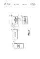
- FIG. 3is a block diagram of a gas distribution system undergoing purification with the apparatus of FIGS. 1-2.
- FIG. 4is a diagram of the distribution inlet, the gas distribution system and the gas distribution system outlet as denoted by the dotted line box of FIG. 3.
- FIGS. 1-2there is shown an apparatus 10 for purifying gas distribution systems.
- the apparatus 10has a gas inlet 12 and a gas outlet 14 having suitable fittings 16 and 18 for connection to gas distribution lines 54.
- a housing 22encloses a resistance heater 24 and a particle filter 26 for the gas.
- the resistance heater 24is connected to the gas inlet 12 and the particle filter 26 is connected between the resistance heater 24 and the gas outlet 14.
- the resistance heaterincludes a sealed tube 27 defining a gas plenum 28.
- a resistance heater element enclosed in a cylindrical Inconel alloy shell 30is centrally disposed in the sealed tube 27.
- a spiral ridge 32winds around the shell 30 to define a spiral path for gas flowing through the plenum 28, as indicated by arrows 34.
- the spiral ridge 32has a narrower pitch near the gas inlet 12 and a wider pitch moving toward the filter 26 end of the plenum 28. This shape forces intimate contact between the gas and the heating element when the gas temperature difference compared to the heating element is greatest.
- An electrical power input 36is connected to the resistance heater element through a rheostat control 38.
- a thermocouple 40is positioned against the heater element shell 30 and is also connected to the rheostat control 38.
- Filter 26is implemented with a sintered stainless steel type filter element, obtainable from various suppliers.
- a control knob 42is connected for adjustment of the rheostat control 38.
- a handle 44is provided on the housing 22 for transport of the apparatus 10.
- the housing 22 and the sealed tube 27are fabricated from a 316L or 304 type stainless steel.
- the apparatus 10is connected by facility lines 51 as shown in FIG. 3 between purge gas source 56 and an inlet 54 of a gas distribution system 52 to be purified with the apparatus 10.
- the resistance heater 24is energized, the purified gas is supplied to the system 52 from the apparatus 10 and the gas is circulated through the gas distribution system 52 until the moisture and particulate levels at the outlet 50 of the distribution system are low enough to meet a desired specification.
- the apparatus 10is then disconnected from the system inlet 54 and the purge gas source 56.
- FIG. 4shows the distribution inlet 54, the gas distribution system 52 and the gas distribution system outlet 50 as denoted by the dotted line box 53 of FIG. 3.
- Inlet 54having valves 60 connected by fitting ends 62 to check valves 64, typically divides the purified gas to different mass flow carriers 66 via filters 68.
- FIG. 4shows, for example, five different mass flow carriers 66.
- Outlet 50then distributes the gas to IC manufacturing equipment 70 as shown in FIG. 3.
- the gas distribution system and methoddoes not require supplying large quantities of purified gas through the system until the output of the system is pure enough.
- the apparatus and methodwill purify a gas distribution system in substantially less time than is required by supplying purified gas through the system until the output of the system is pure enough.
Landscapes
- Engineering & Computer Science (AREA)
- Physics & Mathematics (AREA)
- Thermal Sciences (AREA)
- Chemical & Material Sciences (AREA)
- Combustion & Propulsion (AREA)
- Mechanical Engineering (AREA)
- General Engineering & Computer Science (AREA)
- Filtering Of Dispersed Particles In Gases (AREA)
- Drying Of Gases (AREA)
- Separation Of Gases By Adsorption (AREA)
Abstract
Description
Claims (3)
Priority Applications (8)
| Application Number | Priority Date | Filing Date | Title |
|---|---|---|---|
| US07/741,651US5178651A (en) | 1991-08-07 | 1991-08-07 | Method for purifying gas distribution systems |
| EP92917799AEP0641241B1 (en) | 1991-08-07 | 1992-08-05 | A method for purifying gas distribution systems |
| AU24456/92AAU2445692A (en) | 1991-08-07 | 1992-08-05 | A method for purifying gas distribution systems |
| JP5503820AJPH07500530A (en) | 1991-08-07 | 1992-08-05 | How to purify gas distribution equipment |
| SG1996005638ASG52535A1 (en) | 1991-08-07 | 1992-08-05 | Apparatus and method for purifying gas distribution systems |
| HK98102740AHK1003781A1 (en) | 1991-08-07 | 1992-08-05 | A method for purifying gas distribution systems |
| DE69212167TDE69212167T2 (en) | 1991-08-07 | 1992-08-05 | METHOD FOR CLEANING GAS DISTRIBUTION SYSTEMS |
| PCT/US1992/006505WO1993002768A1 (en) | 1991-08-07 | 1992-08-05 | A method for purifying gas distribution systems |
Applications Claiming Priority (1)
| Application Number | Priority Date | Filing Date | Title |
|---|---|---|---|
| US07/741,651US5178651A (en) | 1991-08-07 | 1991-08-07 | Method for purifying gas distribution systems |
Publications (1)
| Publication Number | Publication Date |
|---|---|
| US5178651Atrue US5178651A (en) | 1993-01-12 |
Family
ID=24981606
Family Applications (1)
| Application Number | Title | Priority Date | Filing Date |
|---|---|---|---|
| US07/741,651Expired - Fee RelatedUS5178651A (en) | 1991-08-07 | 1991-08-07 | Method for purifying gas distribution systems |
Country Status (8)
| Country | Link |
|---|---|
| US (1) | US5178651A (en) |
| EP (1) | EP0641241B1 (en) |
| JP (1) | JPH07500530A (en) |
| AU (1) | AU2445692A (en) |
| DE (1) | DE69212167T2 (en) |
| HK (1) | HK1003781A1 (en) |
| SG (1) | SG52535A1 (en) |
| WO (1) | WO1993002768A1 (en) |
Cited By (8)
| Publication number | Priority date | Publication date | Assignee | Title |
|---|---|---|---|---|
| WO1995020823A1 (en)* | 1994-01-27 | 1995-08-03 | Insync Systems, Inc. | Methods for improving semiconductor processing |
| US5714678A (en)* | 1996-11-26 | 1998-02-03 | American Air Liquide Inc. | Method for rapidly determining an impurity level in a gas source or a gas distribution system |
| US6644353B1 (en) | 1998-03-05 | 2003-11-11 | Swagelok Company | Modular surface mount manifold |
| US20030209277A1 (en)* | 1998-03-05 | 2003-11-13 | Douglas Nordstrom | Modular surface mount manifold assemblies |
| US6944394B2 (en)* | 2002-01-22 | 2005-09-13 | Watlow Electric Manufacturing Company | Rapid response electric heat exchanger |
| US20060070674A1 (en)* | 2004-10-01 | 2006-04-06 | Eidsmore Paul G | Substrate with offset flow passage |
| US7036528B2 (en) | 1998-05-18 | 2006-05-02 | Swagelok Company | Modular surface mount manifold assemblies |
| US20140093227A1 (en)* | 2012-10-02 | 2014-04-03 | Grant McGuffey | Foam heat exchanger for hot melt adhesive or other thermoplastic material dispensing apparatus |
Citations (5)
| Publication number | Priority date | Publication date | Assignee | Title |
|---|---|---|---|---|
| US3777117A (en)* | 1969-03-10 | 1973-12-04 | D Othmer | Electric heat generating system |
| US3934117A (en)* | 1973-03-27 | 1976-01-20 | Schladitz Hermann J | Electric fluid heating device |
| US4147923A (en)* | 1977-10-14 | 1979-04-03 | Davis Oliver T | Electrical filtered air heater |
| US4197095A (en)* | 1978-08-31 | 1980-04-08 | Pall Corporation | Heatless adsorbent fractionators with microprocessor cycle control and process |
| US4501952A (en)* | 1982-06-07 | 1985-02-26 | Graco Inc. | Electric fluid heater temperature control system providing precise control under varying conditions |
- 1991
- 1991-08-07USUS07/741,651patent/US5178651A/ennot_activeExpired - Fee Related
- 1992
- 1992-08-05JPJP5503820Apatent/JPH07500530A/enactivePending
- 1992-08-05SGSG1996005638Apatent/SG52535A1/enunknown
- 1992-08-05WOPCT/US1992/006505patent/WO1993002768A1/enactiveIP Right Grant
- 1992-08-05AUAU24456/92Apatent/AU2445692A/ennot_activeAbandoned
- 1992-08-05HKHK98102740Apatent/HK1003781A1/ennot_activeIP Right Cessation
- 1992-08-05EPEP92917799Apatent/EP0641241B1/ennot_activeExpired - Lifetime
- 1992-08-05DEDE69212167Tpatent/DE69212167T2/ennot_activeExpired - Fee Related
Patent Citations (5)
| Publication number | Priority date | Publication date | Assignee | Title |
|---|---|---|---|---|
| US3777117A (en)* | 1969-03-10 | 1973-12-04 | D Othmer | Electric heat generating system |
| US3934117A (en)* | 1973-03-27 | 1976-01-20 | Schladitz Hermann J | Electric fluid heating device |
| US4147923A (en)* | 1977-10-14 | 1979-04-03 | Davis Oliver T | Electrical filtered air heater |
| US4197095A (en)* | 1978-08-31 | 1980-04-08 | Pall Corporation | Heatless adsorbent fractionators with microprocessor cycle control and process |
| US4501952A (en)* | 1982-06-07 | 1985-02-26 | Graco Inc. | Electric fluid heater temperature control system providing precise control under varying conditions |
Cited By (20)
| Publication number | Priority date | Publication date | Assignee | Title |
|---|---|---|---|---|
| WO1995020823A1 (en)* | 1994-01-27 | 1995-08-03 | Insync Systems, Inc. | Methods for improving semiconductor processing |
| SG165131A1 (en)* | 1994-01-27 | 2010-10-28 | Insync Systems Inc | Moisture removal in semiconductor processing |
| US5714678A (en)* | 1996-11-26 | 1998-02-03 | American Air Liquide Inc. | Method for rapidly determining an impurity level in a gas source or a gas distribution system |
| EP0844479A3 (en)* | 1996-11-26 | 2000-10-04 | L'air Liquide, Societe Anonyme Pour L'etude Et L'exploitation Des Procedes Georges Claude | Method for rapidly determining an impurity level in a gas source or a gas distribution system |
| US7404417B2 (en) | 1998-03-05 | 2008-07-29 | Swagelok Company | Modular surface mount manifold |
| US20030209277A1 (en)* | 1998-03-05 | 2003-11-13 | Douglas Nordstrom | Modular surface mount manifold assemblies |
| US6776193B2 (en) | 1998-03-05 | 2004-08-17 | Swagelok Company | Modular surface mount manifold |
| US6938644B2 (en) | 1998-03-05 | 2005-09-06 | Swagelok Company | Modular surface mount manifold |
| US6644353B1 (en) | 1998-03-05 | 2003-11-11 | Swagelok Company | Modular surface mount manifold |
| US20050263197A1 (en)* | 1998-03-05 | 2005-12-01 | Eidsmore Paul E | Modular surface mount manifold |
| US7686041B2 (en) | 1998-03-05 | 2010-03-30 | Swagelok Company | Modular surface mount manifold assemblies |
| US20040112447A1 (en)* | 1998-03-05 | 2004-06-17 | Swagelok Company | Modular Surface Mount Manifold |
| US20060157130A1 (en)* | 1998-03-05 | 2006-07-20 | Eidsmore Paul G | Modular surface mount manifold assemblies |
| US7195037B2 (en) | 1998-03-05 | 2007-03-27 | Swagelok Company | Modular surface mount manifold |
| US20070157984A1 (en)* | 1998-03-05 | 2007-07-12 | Swagelok Company | Modular surface mount manifold |
| US7036528B2 (en) | 1998-05-18 | 2006-05-02 | Swagelok Company | Modular surface mount manifold assemblies |
| US6944394B2 (en)* | 2002-01-22 | 2005-09-13 | Watlow Electric Manufacturing Company | Rapid response electric heat exchanger |
| US20060070674A1 (en)* | 2004-10-01 | 2006-04-06 | Eidsmore Paul G | Substrate with offset flow passage |
| US20140093227A1 (en)* | 2012-10-02 | 2014-04-03 | Grant McGuffey | Foam heat exchanger for hot melt adhesive or other thermoplastic material dispensing apparatus |
| US9338828B2 (en)* | 2012-10-02 | 2016-05-10 | Illinois Tool Works Inc. | Foam heat exchanger for hot melt adhesive or other thermoplastic material dispensing apparatus |
Also Published As
| Publication number | Publication date |
|---|---|
| WO1993002768A1 (en) | 1993-02-18 |
| JPH07500530A (en) | 1995-01-19 |
| EP0641241A1 (en) | 1995-03-08 |
| SG52535A1 (en) | 1998-09-28 |
| AU2445692A (en) | 1993-03-02 |
| EP0641241A4 (en) | 1994-06-01 |
| HK1003781A1 (en) | 1998-11-06 |
| DE69212167D1 (en) | 1996-08-14 |
| EP0641241B1 (en) | 1996-07-10 |
| DE69212167T2 (en) | 1996-11-28 |
Similar Documents
| Publication | Publication Date | Title |
|---|---|---|
| DE69839083T2 (en) | gas panel | |
| US5178651A (en) | Method for purifying gas distribution systems | |
| EP0488117A1 (en) | Gas flow distribution system | |
| EP0844431B1 (en) | System and method for controlled delivery of liquefied gases | |
| HK1003781B (en) | A method for purifying gas distribution systems | |
| KR20000052913A (en) | Gas panel | |
| US6283143B1 (en) | System and method for providing an integrated gas stick | |
| EP0062174B1 (en) | Apparatus treating specimens at raised temperatures | |
| EP0617293A2 (en) | Dust particle exposure chamber | |
| US6168085B1 (en) | System and method for cascade control of temperature and humidity for semi-conductor manufacturing environments | |
| US5902551A (en) | Process gas docking station with point-of-use filter for receiving removable purifier cartridges | |
| US6395064B1 (en) | System and method for purifying and distributing chemical gases | |
| MX9601306A (en) | Method to remove organic halogenated molecules from gaseous streams and related plant. | |
| EP0390072B1 (en) | Atomic absorption spectrophotometer and electromagnetic shut-off valve for use therein | |
| KR19990087058A (en) | A method of supplying gas to the chamber and a method of controlling the content of a given component in the chamber atmosphere | |
| JPS61270231A (en) | Heat-treating apparatus | |
| US6065489A (en) | Ozone flow rate control device | |
| US6478040B1 (en) | Gas supplying apparatus and gas substitution method | |
| US5287873A (en) | Installation and process for the distribution of very high purity nitrogen | |
| US5794114A (en) | Ozonizer | |
| KR200163640Y1 (en) | Cleaning system for the semiconductor exhaust gas | |
| DE10151321A1 (en) | Cyclone tube pressure reducer for gas technology is switched in series with throttle valve, and has warm gas-containing pipe sections enclosing all cold gas-containing pipe sections | |
| EP0778453B1 (en) | Furnace with an inert gas flowed toward the inlet and/or outlet sections | |
| JPH04200893A (en) | Reflow apparatus | |
| Foster et al. | Helium-Purification Unit for High-Purity Inert-Atmosphere Boxes |
Legal Events
| Date | Code | Title | Description |
|---|---|---|---|
| AS | Assignment | Owner name:INSYNC SYSTEMS, INC., CALIFORNIA Free format text:ASSIGNMENT OF ASSIGNORS INTEREST;ASSIGNORS:BALMA, FRANK;ELLIOT, BRENT;REEL/FRAME:006862/0412 Effective date:19930225 | |
| FEPP | Fee payment procedure | Free format text:PAYOR NUMBER ASSIGNED (ORIGINAL EVENT CODE: ASPN); ENTITY STATUS OF PATENT OWNER: LARGE ENTITY | |
| FEPP | Fee payment procedure | Free format text:PAT HLDR NO LONGER CLAIMS SMALL ENT STAT AS INDIV INVENTOR (ORIGINAL EVENT CODE: LSM1); ENTITY STATUS OF PATENT OWNER: LARGE ENTITY | |
| FPAY | Fee payment | Year of fee payment:4 | |
| AS | Assignment | Owner name:CREDIT AGRICOLE INDOSVEZ, AS COLLATERAL AGENT, NEW Free format text:SECURITY AGREEMENT;ASSIGNOR:INSYNC SYSTEMS, INC.;REEL/FRAME:009103/0583 Effective date:19980330 | |
| FPAY | Fee payment | Year of fee payment:8 | |
| AS | Assignment | Owner name:CELERITY GROUP, INC., CALIFORNIA Free format text:CHANGE OF NAME;ASSIGNOR:KINETICS FLUID SYSTEMS, INC.;REEL/FRAME:014192/0712 Effective date:20011201 Owner name:KINETICS FLUID SYSTEMS, INC., CALIFORNIA Free format text:MERGER;ASSIGNOR:INSYNC SYSTEMS, INC.;REEL/FRAME:014192/0720 Effective date:20011201 | |
| REMI | Maintenance fee reminder mailed | ||
| AS | Assignment | Owner name:KINETICS GROUP, INC., TEXAS Free format text:SECURITY AGREEMENT RELEASE;ASSIGNOR:SCOTIA, BANK OF NOVA;REEL/FRAME:015503/0183 Effective date:20041223 Owner name:CELERITY GROUP, INC., TEXAS Free format text:SECURITY AGREEMENT RELEASE;ASSIGNOR:SCOTIA, BANK OF NOVA;REEL/FRAME:015503/0183 Effective date:20041223 Owner name:MEGA SYSTEMS & CHEMICALS, INC., TEXAS Free format text:SECURITY AGREEMENT RELEASE;ASSIGNOR:SCOTIA, BANK OF NOVA;REEL/FRAME:015503/0183 Effective date:20041223 Owner name:UNIT INSTRUMENTS, INC., TEXAS Free format text:SECURITY AGREEMENT RELEASE;ASSIGNOR:SCOTIA, BANK OF NOVA;REEL/FRAME:015503/0183 Effective date:20041223 Owner name:FTS SYSTEMS, INC., TEXAS Free format text:SECURITY AGREEMENT RELEASE;ASSIGNOR:SCOTIA, BANK OF NOVA;REEL/FRAME:015503/0183 Effective date:20041223 Owner name:INSYNC SYSTEMS, INC., TEXAS Free format text:SECURITY AGREEMENT RELEASE;ASSIGNOR:SCOTIA, BANK OF NOVA;REEL/FRAME:015503/0183 Effective date:20041223 Owner name:THOMAS CONVEYOR COMPANY, TEXAS Free format text:SECURITY AGREEMENT RELEASE;ASSIGNOR:SCOTIA, BANK OF NOVA;REEL/FRAME:015503/0183 Effective date:20041223 | |
| LAPS | Lapse for failure to pay maintenance fees | ||
| STCH | Information on status: patent discontinuation | Free format text:PATENT EXPIRED DUE TO NONPAYMENT OF MAINTENANCE FEES UNDER 37 CFR 1.362 | |
| FP | Lapsed due to failure to pay maintenance fee | Effective date:20050112 | |
| AS | Assignment | Owner name:CELERITY, INC., TEXAS Free format text:CONFIRMATORY ASSIGNMENT;ASSIGNOR:CELERITY GROUP, INC.;REEL/FRAME:016686/0262 Effective date:20050324 | |
| AS | Assignment | Owner name:INSYNC SYSTEMS, INC., CALIFORNIA Free format text:RELEASE BY SECURED PARTY;ASSIGNOR:CREDIT AGRICOLE INDOSUEZ;REEL/FRAME:022793/0156 Effective date:19981210 | |
| AS | Assignment | Owner name:SILICON VALLEY BANK, CALIFORNIA Free format text:SECURITY AGREEMENT;ASSIGNORS:ICICLE ACQUISITION HOLDING B.V.;ICICLE ACQUISITION HOLDING, LLC;ICHOR SYSTEMS, INC.;AND OTHERS;REEL/FRAME:027466/0083 Effective date:20111230 | |
| AS | Assignment | Owner name:ICHOR SYSTEMS, INC., TEXAS Free format text:RELEASE BY SECURED PARTY;ASSIGNOR:THE BANK OF NEW YORK MELLON;REEL/FRAME:027564/0092 Effective date:20120119 | |
| AS | Assignment | Owner name:ICICLE ACQUISITION HOLDING B.V., NETHERLANDS Free format text:RELEASE BY SECURED PARTY;ASSIGNOR:SILICON VALLEY BANK, AS ADMINISTRATIVE AGENT;REEL/FRAME:036299/0365 Effective date:20150811 Owner name:ICHOR HOLDINGS, LLC (F/K/A ICICLE ACQUISITION HOLD Free format text:RELEASE BY SECURED PARTY;ASSIGNOR:SILICON VALLEY BANK, AS ADMINISTRATIVE AGENT;REEL/FRAME:036299/0365 Effective date:20150811 Owner name:PRECISION FLOW TECHNOLOGIES, INC., NEW YORK Free format text:RELEASE BY SECURED PARTY;ASSIGNOR:SILICON VALLEY BANK, AS ADMINISTRATIVE AGENT;REEL/FRAME:036299/0365 Effective date:20150811 Owner name:ICHOR SYSTEMS, INC., CALIFORNIA Free format text:RELEASE BY SECURED PARTY;ASSIGNOR:SILICON VALLEY BANK, AS ADMINISTRATIVE AGENT;REEL/FRAME:036299/0365 Effective date:20150811 |