US5178464A - Balance infrared thermometer and method for measuring temperature - Google Patents
Balance infrared thermometer and method for measuring temperatureDownload PDFInfo
- Publication number
- US5178464A US5178464AUS07/687,651US68765191AUS5178464AUS 5178464 AUS5178464 AUS 5178464AUS 68765191 AUS68765191 AUS 68765191AUS 5178464 AUS5178464 AUS 5178464A
- Authority
- US
- United States
- Prior art keywords
- temperature
- detector
- signal
- thermal
- changing
- Prior art date
- Legal status (The legal status is an assumption and is not a legal conclusion. Google has not performed a legal analysis and makes no representation as to the accuracy of the status listed.)
- Expired - Fee Related
Links
- 238000000034methodMethods0.000titleclaimsdescription12
- 230000005855radiationEffects0.000claimsabstractdescription29
- 238000009413insulationMethods0.000claimsdescription4
- 230000005679Peltier effectEffects0.000claimsdescription2
- 238000010438heat treatmentMethods0.000claimsdescription2
- 230000004044responseEffects0.000description6
- 230000008859changeEffects0.000description5
- 238000009529body temperature measurementMethods0.000description4
- 238000013459approachMethods0.000description3
- 230000008901benefitEffects0.000description3
- 238000005259measurementMethods0.000description3
- 230000032683agingEffects0.000description2
- 238000004364calculation methodMethods0.000description2
- 238000012986modificationMethods0.000description2
- 230000004048modificationEffects0.000description2
- 230000003287optical effectEffects0.000description2
- 238000006467substitution reactionMethods0.000description2
- 239000000758substrateSubstances0.000description2
- 239000011248coating agentSubstances0.000description1
- 238000000576coating methodMethods0.000description1
- 238000010276constructionMethods0.000description1
- 238000001816coolingMethods0.000description1
- 238000012937correctionMethods0.000description1
- 230000008878couplingEffects0.000description1
- 238000010168coupling processMethods0.000description1
- 238000005859coupling reactionMethods0.000description1
- 238000013461designMethods0.000description1
- 238000010586diagramMethods0.000description1
- 239000012212insulatorSubstances0.000description1
- 239000006233lamp blackSubstances0.000description1
- 239000000523sampleSubstances0.000description1
- 239000004065semiconductorSubstances0.000description1
- 230000003595spectral effectEffects0.000description1
- 239000002470thermal conductorSubstances0.000description1
- 238000004861thermometryMethods0.000description1
- 239000010409thin filmSubstances0.000description1
- 238000002834transmittanceMethods0.000description1
Images
Classifications
- G—PHYSICS
- G01—MEASURING; TESTING
- G01J—MEASUREMENT OF INTENSITY, VELOCITY, SPECTRAL CONTENT, POLARISATION, PHASE OR PULSE CHARACTERISTICS OF INFRARED, VISIBLE OR ULTRAVIOLET LIGHT; COLORIMETRY; RADIATION PYROMETRY
- G01J5/00—Radiation pyrometry, e.g. infrared or optical thermometry
- G01J5/52—Radiation pyrometry, e.g. infrared or optical thermometry using comparison with reference sources, e.g. disappearing-filament pyrometer
Definitions
- This inventionrelates generally to thermometry and more specifically, to an infrared radiation thermometer.
- the temperature of an objectcan be determined by two methods: either by a contact thermometer having a probe which comes into physical contact with the measured object, or by a non-contact thermometer which measures infrared (IR) radiation exchange between its radiation detector and an object (target).
- IRinfrared
- Variations in internal temperature of an infrared thermometeraffect its accuracy and must always be taken into account when the temperature of an object is measured.
- thermometer's interior temperatureconstant by use of a thermostat as described in U.S. Pat. No. 4,602,642 issued to O'Hara et al.
- Another methodis to control the temperature of the sensor's surface, maintaining it at a predetermined level as in U.S. Pat. No. 4,854,730 issued to Fraden.
- Still another methodis to control temperature of the sensor's housing at a level which brings the thermal detector output signal essentially to zero level as in U.S. Pat. No. 4,900,162 issued to Beckman et al.
- the above mentioned U.S. Pat. No. 4,854,730 issued to Fraden and U.S. Pat. No. 4,634,294 issued to Christo et al.teach compensation for ambient temperature variations by using an additional ambient temperature sensor, the signal of which is used for calculation of the correction.
- the same radiation detector for the object targetmeasures infrared radiation from a reference target of known temperature.
- the present inventionis designed to provide an infrared thermometer which is less sensitive to variations in ambient temperature, and less susceptible to variabilities inherent in internal elements.
- thermometerwith symmetrical sensor, and a thermal reference source.
- Another objectis to provide an infrared thermometer with symmetrical sensor, thermal reference source, and a null type radiometer.
- the present inventionprovides a radiation thermometer with a sensor that includes two thermal energy detectors, thermally insulated from one another.
- the first detectoris warmed up or cooled down by infrared radiation between the object and the first detector, while the second detector is shielded from radiation from the object, and is warmed up or cooled down by an internal reference temperature source.
- Each detectorprovides a signal that is representative of the temperature of the detector.
- the two detectorsare brought substantially to a known temperature ratio, preferably to the same temperature, by heater/cooler means.
- a heater/cooler meanschanges the temperature of an item by exchanging thermal energy with the item.
- the temperature of the targetcan be determined when the detectors of the sensor are in a balanced state which means, that heat received from the reference source is a known ratio to that received from the object target.
- a control circuitwhich receives signals from the detectors operates the heating or cooling reference temperature source that brings the temperature of the second detector to the known temperature ratio with the first detector by exchange of thermal or heat energy between the heater/cooler source and the second detector.
- the detectorsare in balance, that is when the detector temperature ratio is established, the temperature, preferably of the reference source, is measured by a third temperature detector, and a processor which receives a signal from the third detector calculates the temperature of the object target.
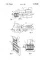
- FIG. 1is a schematic view of a balance radiation thermometer with a symmetrical sensor.
- FIG. 2is a schematic diagram of a controller with resistive bridge.
- FIG. 3is cross section view of a resistive thermal energy detector.
- FIG. 4is a schematic view of a radiation sensor with conductive heat balance.
- An infrared thermometerrelies on thermal radiation exchange between an object (target) and a sensor. If an object is warmer than sensor, the latter's temperature increase upon its exposure to a target. The sensor's temperature increase may be used for the target's temperature measurements.
- Sensor 1comprises thermal energy detector 2 which is supported by base 13. Sensor 1 can be exposed to infrared radiation from the object target via window 31. Thermal energy detector 4, supported by base 3, can be exposed to heater/cooler 5 via window 32. Each detector provides a signal when subjected to infrared energy. Thermal energy detector 33 is attached to heater/cooler 5 to measure the temperature of 5.
- Detector 4shielded from the object target while it is subjected to the same other thermal related influences as detector 2.
- detectors 2 and 4are separated by thermal insulator 34 to assure a very low heat exchange between them.
- the temperature of heater/cooler 5is continuously monitored by detector 33.
- Heater/cooler 5may be adapted to have emissive characteristics close to those of a target in the wavelength of interest.
- Controller 12has the function of bringing the first and second detectors 2 and 4 into a balanced state. When the detectors are balanced by controller 12, the output signal from third detector 33 can be used by processor 8 to calculate the temperature of the object target.
- One major advantage of this arrangementis the ability to make the sensor fully symmetrical which contributes to the rejection of thermal and electrical interferences.
- Output signals from both thermal energy detectors 2 and 4are channeled via lines 6 and 7 to controller 12, the function of which is to compare those responses from detectors 2 and 4 and to control heater/cooler 5 via lines 10 and 11.
- the signal from line 40is fed into processor 8 for deriving a numerical value which appears as output 9. It is representative of the object target temperature.
- a signalis received by the controller from thermal energy detector 2 via line 6.
- the controller's functionis to bring the temperature of thermal energy detector 4 to a predetermined ratio to that of detector 2, preferably to the same temperature as detector 2.
- the signal in line 40can be used by processor 8 calculate the temperature of the object target.
- FIG. 2shows a typical controller/heater circuit which may be used in the present invention.
- a resistive bridgeis formed by constant resistors 24 and 25, and thermistor detectors 2 and 4. Thermistor 2 receives heat energy from the object target, while thermistor 4 receives heat energy from heater 5.
- Amplifier 26delivers signal differentials to compensating network 27 which controls power to heater 5 for delivering sufficient heat to thermistor 4 to bring it into in proper temperature balance with thermistor 2.
- Calculation of the temperature of the objectcan be based on one of conventional algorithms, for example, on the Stefan-Boltzmann law, and must include such factors as energy loss from optical components, emissivities of the targets and detectors, etc. It should be noted that contrary to the above cited U.S. Pat. No. 4,900,162 which essentially requires zero output signal from the radiation detector, temperature measurement according to the present invention is based on the balanced state of two parts of the sensor whatever signal values from these parts might be.
- detector 4is kept at the same temperature as detector 2.
- thermometer 1When no infrared radiation enters sensor 1, the temperatures of all internal parts of the sensor are in equilibrium and thermal energy detectors 2 and 4 generate substantially equal signals. These signals a fed into controller 12 which generates no signal change in lines 10 and 11. Output line 9 provides a signal related to the thermometer's internal temperature.
- thermal energy detector 2When thermal energy detector 2 is subjected to object target infrared radiation, its temperature changes. This results in a signal change in line 6. The signal is compared with a signal in line 7 which, at this moment, remains substantially unchanged. The comparison is done by controller 12. In response, it generates electric current in lines 10 and 11 to increase or decrease the temperature of heater/cooler 5. With heater/cooler 5 exposure to thermal energy detector 4, the selection of temperature change in 4 cause further signal change in line 7.
- Controller 12regulates the current in lines 10 and 11 in such a manner as to bring the signals in lines 6 and 7 as close as possible to one another.
- Detector 33monitors the temperature of heater/cooler 5, and provides a signal that is indicative of the temperature to processor 8 by way of line 40.
- temperature processor 8uses the signal from detector 33 in calculating the temperature of the object target and presents it in output line 9. In other words, a temperature balance of detectors 2 and 4 is required to complete the measurement.
- the predetermined ratiobe other than unity.
- detector 4may be kept at temperatures 30 degrees F.above detector 2, so that heater/cooler 5 need be only a heater to maintain the ratio, even if detector 2 is exposed to an object target that is below the temperature of sensor 1.
- thermometers 2 and 4can be thermopiles.
- two identical detectors like the one shown in FIG. 3can be used.
- active infrared detectorslike those described in U.S. Pat. No. 4,854,730 can be used.
- a thermistor, semiconductor, thermocouple, RTD or any other appropriate temperature sensorcan be used for detector 33.
- window 32Since the front end of an infrared thermometer is usually protected by a window 31, having an appropriate transmittance band, window 32 may be identical in order to match the thermal loss of window 31.
- heater/cooler 5can be resistive heater.
- heater/cooler 5may incorporate a thermoelectric device operating on Peltier effect so that it may heat or cool detector 4.
- FIG. 3shows one example of a detector 2 constructed according to the present invention.
- Frame 16supports thin substrate 17 having preferably a high thermal conductivity and a low thermal capacity.
- Front surface 19carries a thin film temperature sensitive resistor (thermistor) 18 which can be connected to an external circuit via first contact 14 and second contact 15.
- Front surface 19can be given an infrared absorptive coating, such as lampblack, to increase its emissivity over a spectral range of interest.
- the temperature of substrate 17changes. This results in corresponding change in resistance of thermistor 18.
- FIG. 4Another method to provide thermal exchange between heater/cooler 5 and detector 4 is by means of thermal conduction, as shown in FIG. 4.
- the sensoris analogous to that of FIG. 1, except that elements 4, 5, and 33 are in intimate thermal contact. This assures that thermal energy is transferred between elements 4, 5, and 33 by conduction.
- detectors 2 and 4may be respectively "cold” and “hot” junctions of a single thermopile detector which is a sensor of choice in many infrared thermometers.
- Insulation 34assures that there is minimal thermal exchange between them and detector 2.
Landscapes
- Physics & Mathematics (AREA)
- General Physics & Mathematics (AREA)
- Spectroscopy & Molecular Physics (AREA)
- Radiation Pyrometers (AREA)
Abstract
Description
Claims (6)
Priority Applications (1)
| Application Number | Priority Date | Filing Date | Title |
|---|---|---|---|
| US07/687,651US5178464A (en) | 1991-04-19 | 1991-04-19 | Balance infrared thermometer and method for measuring temperature |
Applications Claiming Priority (1)
| Application Number | Priority Date | Filing Date | Title |
|---|---|---|---|
| US07/687,651US5178464A (en) | 1991-04-19 | 1991-04-19 | Balance infrared thermometer and method for measuring temperature |
Publications (1)
| Publication Number | Publication Date |
|---|---|
| US5178464Atrue US5178464A (en) | 1993-01-12 |
Family
ID=24761254
Family Applications (1)
| Application Number | Title | Priority Date | Filing Date |
|---|---|---|---|
| US07/687,651Expired - Fee RelatedUS5178464A (en) | 1991-04-19 | 1991-04-19 | Balance infrared thermometer and method for measuring temperature |
Country Status (1)
| Country | Link |
|---|---|
| US (1) | US5178464A (en) |
Cited By (43)
| Publication number | Priority date | Publication date | Assignee | Title |
|---|---|---|---|---|
| US5485011A (en)* | 1994-01-28 | 1996-01-16 | Larry C. Y. Lee | Two-sided integrated-circuit PIR sensor package |
| US5516010A (en)* | 1984-10-23 | 1996-05-14 | Sherwood Medical Company | Sanitary speculum for tympanic thermometer probe |
| US5614716A (en)* | 1996-04-26 | 1997-03-25 | Infratemp, Inc. | Alternating current method and apparatus for ambient temperature compensation for modulated energy sensors |
| US5620254A (en)* | 1995-03-08 | 1997-04-15 | Servo Corporation Of America | Thermal detector modulation scheme |
| US5626147A (en)* | 1993-11-23 | 1997-05-06 | Thermoscan, Inc. | Tympanic thermometer |
| US5666956A (en)* | 1996-05-20 | 1997-09-16 | Buchert; Janusz Michal | Instrument and method for non-invasive monitoring of human tissue analyte by measuring the body's infrared radiation |
| US5725308A (en)* | 1994-12-23 | 1998-03-10 | Rtd Technology, Inc. | Quick registering thermometer |
| US5823966A (en)* | 1997-05-20 | 1998-10-20 | Buchert; Janusz Michal | Non-invasive continuous blood glucose monitoring |
| US5833367A (en) | 1996-11-12 | 1998-11-10 | Trutek, Inc. | Tympanic thermometer probe cover |
| WO1999001726A1 (en)* | 1997-07-03 | 1999-01-14 | Koninklijke Philips Electronics N.V. | Device for measuring the temperature of an object by means of a thermocouple infrared sensor, and thermal electrical appliance including such a device |
| WO1999034729A1 (en) | 1998-01-12 | 1999-07-15 | Mdi Instruments, Inc. | Ear examining device with temperature sensor |
| US5967992A (en) | 1998-06-03 | 1999-10-19 | Trutex, Inc. | Radiometric temperature measurement based on empirical measurements and linear functions |
| US6001066A (en) | 1997-06-03 | 1999-12-14 | Trutek, Inc. | Tympanic thermometer with modular sensing probe |
| US6030117A (en) | 1996-11-12 | 2000-02-29 | Trutek, Inc. | Tympanic thermometer probe cover |
| WO2000024312A1 (en) | 1998-10-23 | 2000-05-04 | Becton, Dickinson And Company | Sensing ear temperature, acoustic reflectance and chemical components in the ear |
| US6109782A (en)* | 1995-12-28 | 2000-08-29 | Omron Corporation | Infrared thermometer |
| US6123454A (en) | 1999-06-11 | 2000-09-26 | Trutek, Inc. | Tympanic thermometer disposable probe cover with further stretching prevention structure |
| US20020193703A1 (en)* | 2001-06-19 | 2002-12-19 | Omron Corporation | Infrared clinical thermometer |
| US20040114661A1 (en)* | 2001-04-09 | 2004-06-17 | Exergen Corporation | Radiation detector with passive air purge and reduced noise |
| US20040122338A1 (en)* | 1988-12-06 | 2004-06-24 | Exergen Corporation | Radiation detector probe |
| US20040152991A1 (en)* | 1998-09-11 | 2004-08-05 | Exergen Corporation | Temporal artery temperature detector |
| US20040220458A1 (en)* | 2003-05-02 | 2004-11-04 | Burd John F. | Method and instruments for non-invasive analyte measurement |
| US20040240516A1 (en)* | 2002-12-12 | 2004-12-02 | James Harr | Thermal tympanic thermometer tip |
| US20050012588A1 (en)* | 2003-07-16 | 2005-01-20 | Sultan Michel F. | Temperature sensor apparatus and method |
| US20050018749A1 (en)* | 2001-06-04 | 2005-01-27 | Omron Corporation | Infrared clinical thermometer and temperature state estimation method, information notification method, and measurement operation method thereof |
| US20050085701A1 (en)* | 2003-10-21 | 2005-04-21 | Burd John F. | Methods for non-invasive analyte measurement from the conjunctiva |
| US6968222B2 (en) | 2003-05-02 | 2005-11-22 | Oculir, Inc. | Methods and device for non-invasive analyte measurement |
| US20060224057A1 (en)* | 2003-10-21 | 2006-10-05 | Oculir, Inc. | Methods for non-invasive analyte measurement |
| US20060239332A1 (en)* | 2002-12-12 | 2006-10-26 | Sherwood Services Ag | Thermal tympanic thermometer |
| US20060258919A1 (en)* | 2004-04-14 | 2006-11-16 | Oculir, Inc. | Non-Invasive Analyte Measurement Device for Measuring Tears and Other Ocular Elements Using Electromagnetic Radiation and Method of Using the Same |
| US20080009688A1 (en)* | 2004-04-14 | 2008-01-10 | Oculir, Inc. | Methods for non-invasive analyte measurement |
| US20090048581A1 (en)* | 2007-08-15 | 2009-02-19 | Eric Sebban | Aspirator assembly |
| US20090076441A1 (en)* | 2007-08-15 | 2009-03-19 | Eric Sebban | Aspirator assembly |
| US20090097529A1 (en)* | 2006-04-07 | 2009-04-16 | Preh Gmbh | Sensor arrangement for the climate control of a motor vehicle |
| USD594968S1 (en) | 2007-08-15 | 2009-06-23 | Eric Sebban | Aspirator assembly |
| US20110194585A1 (en)* | 2010-02-09 | 2011-08-11 | Abhishek Shrivastava | Multiple object non-contact thermometer |
| US20110228810A1 (en)* | 2010-02-09 | 2011-09-22 | O'hara Gary | Multiple object talking non-contact thermometer |
| EP2437039A2 (en) | 2010-09-30 | 2012-04-04 | Medisim Ltd. | Ergonomic hand held thermometer |
| US20150085897A1 (en)* | 2013-09-26 | 2015-03-26 | Rosemount Inc. | Infrared sensor |
| ES2539408A1 (en)* | 2013-12-27 | 2015-06-30 | Instituto Nacional De Técnica Aeroespacial "Esteban Terradas" | Autocalibrable infrared meter and self-calibration procedure of said meter |
| US20180252587A1 (en)* | 2013-07-02 | 2018-09-06 | Exergen Corporation | Method For Temperature Measurements Of Surfaces With A Low, Unknown And/Or Variable Emissivity |
| US11432375B2 (en) | 2017-10-31 | 2022-08-30 | Adasky, Ltd. | Protective window for resistive heating |
| US11706380B2 (en) | 2020-09-17 | 2023-07-18 | Adasky, Ltd. | Radiometric camera with black body elements for screening infectious disease carriers and method for calibrating a thermal camera having internal black body elements |
Citations (17)
| Publication number | Priority date | Publication date | Assignee | Title |
|---|---|---|---|---|
| US2710550A (en)* | 1954-06-07 | 1955-06-14 | Armzen Company | Planetary reducing apparatus and process |
| US3023398A (en)* | 1958-04-09 | 1962-02-27 | Charles L Siegert | Infra-red radiation monitor |
| US3694624A (en)* | 1969-07-16 | 1972-09-26 | Beckman Instruments Gmbh | Infrared radiator arrangement |
| US3768059A (en)* | 1972-05-15 | 1973-10-23 | Barber Colman Co | Ambient compensated solar sensor |
| US4005605A (en)* | 1974-07-22 | 1977-02-01 | Mikron Instrument Company, Inc. | Remote reading infrared thermometer |
| US4315430A (en)* | 1980-02-21 | 1982-02-16 | Honeywell Inc. | Gas calorific content analyzing apparatus |
| US4435092A (en)* | 1980-07-25 | 1984-03-06 | Nippon Steel Corporation | Surface temperature measuring apparatus for object within furnace |
| US4602642A (en)* | 1984-10-23 | 1986-07-29 | Intelligent Medical Systems, Inc. | Method and apparatus for measuring internal body temperature utilizing infrared emissions |
| US4634294A (en)* | 1979-09-12 | 1987-01-06 | Raytek, Inc. | Hand-held digital temperature measuring instrument |
| US4741626A (en)* | 1985-11-11 | 1988-05-03 | Minolta Camera Kabushiki Kaisha | Pyroelectric thermal sensor |
| US4751388A (en)* | 1985-09-11 | 1988-06-14 | Siemens Aktiengesellschaft | Sensor element in a retaining frame for a pyrodetector and method for the manufacture thereof |
| US4797840A (en)* | 1985-04-17 | 1989-01-10 | Thermoscan Inc. | Infrared electronic thermometer and method for measuring temperature |
| US4853538A (en)* | 1987-07-31 | 1989-08-01 | U.S. Philips Corp. | Radiation detector arrangements and methods |
| US4854730A (en)* | 1987-08-13 | 1989-08-08 | Jacob Fraden | Radiation thermometer and method for measuring temperature |
| US4900162A (en)* | 1989-03-20 | 1990-02-13 | Ivac Corporation | Infrared thermometry system and method |
| US4932789A (en)* | 1988-04-12 | 1990-06-12 | Citizen Watch Co., Ltd. | Radiation clinical thermometer |
| US4969748A (en)* | 1989-04-13 | 1990-11-13 | Peak Systems, Inc. | Apparatus and method for compensating for errors in temperature measurement of semiconductor wafers during rapid thermal processing |
- 1991
- 1991-04-19USUS07/687,651patent/US5178464A/ennot_activeExpired - Fee Related
Patent Citations (17)
| Publication number | Priority date | Publication date | Assignee | Title |
|---|---|---|---|---|
| US2710550A (en)* | 1954-06-07 | 1955-06-14 | Armzen Company | Planetary reducing apparatus and process |
| US3023398A (en)* | 1958-04-09 | 1962-02-27 | Charles L Siegert | Infra-red radiation monitor |
| US3694624A (en)* | 1969-07-16 | 1972-09-26 | Beckman Instruments Gmbh | Infrared radiator arrangement |
| US3768059A (en)* | 1972-05-15 | 1973-10-23 | Barber Colman Co | Ambient compensated solar sensor |
| US4005605A (en)* | 1974-07-22 | 1977-02-01 | Mikron Instrument Company, Inc. | Remote reading infrared thermometer |
| US4634294A (en)* | 1979-09-12 | 1987-01-06 | Raytek, Inc. | Hand-held digital temperature measuring instrument |
| US4315430A (en)* | 1980-02-21 | 1982-02-16 | Honeywell Inc. | Gas calorific content analyzing apparatus |
| US4435092A (en)* | 1980-07-25 | 1984-03-06 | Nippon Steel Corporation | Surface temperature measuring apparatus for object within furnace |
| US4602642A (en)* | 1984-10-23 | 1986-07-29 | Intelligent Medical Systems, Inc. | Method and apparatus for measuring internal body temperature utilizing infrared emissions |
| US4797840A (en)* | 1985-04-17 | 1989-01-10 | Thermoscan Inc. | Infrared electronic thermometer and method for measuring temperature |
| US4751388A (en)* | 1985-09-11 | 1988-06-14 | Siemens Aktiengesellschaft | Sensor element in a retaining frame for a pyrodetector and method for the manufacture thereof |
| US4741626A (en)* | 1985-11-11 | 1988-05-03 | Minolta Camera Kabushiki Kaisha | Pyroelectric thermal sensor |
| US4853538A (en)* | 1987-07-31 | 1989-08-01 | U.S. Philips Corp. | Radiation detector arrangements and methods |
| US4854730A (en)* | 1987-08-13 | 1989-08-08 | Jacob Fraden | Radiation thermometer and method for measuring temperature |
| US4932789A (en)* | 1988-04-12 | 1990-06-12 | Citizen Watch Co., Ltd. | Radiation clinical thermometer |
| US4900162A (en)* | 1989-03-20 | 1990-02-13 | Ivac Corporation | Infrared thermometry system and method |
| US4969748A (en)* | 1989-04-13 | 1990-11-13 | Peak Systems, Inc. | Apparatus and method for compensating for errors in temperature measurement of semiconductor wafers during rapid thermal processing |
Cited By (69)
| Publication number | Priority date | Publication date | Assignee | Title |
|---|---|---|---|---|
| US5707343A (en)* | 1984-10-23 | 1998-01-13 | O'hara; Gary J. | Disposable sanitary speculum for timpanic thermometer probe |
| US5516010A (en)* | 1984-10-23 | 1996-05-14 | Sherwood Medical Company | Sanitary speculum for tympanic thermometer probe |
| US5980451A (en) | 1984-10-23 | 1999-11-09 | Sherwood Services Ag | Disposable speculum with membrane bonding ring |
| US20060062274A1 (en)* | 1988-12-06 | 2006-03-23 | Exergen Corporation | Radiation detector probe |
| US20040122338A1 (en)* | 1988-12-06 | 2004-06-24 | Exergen Corporation | Radiation detector probe |
| US5626147A (en)* | 1993-11-23 | 1997-05-06 | Thermoscan, Inc. | Tympanic thermometer |
| US5485011A (en)* | 1994-01-28 | 1996-01-16 | Larry C. Y. Lee | Two-sided integrated-circuit PIR sensor package |
| US5725308A (en)* | 1994-12-23 | 1998-03-10 | Rtd Technology, Inc. | Quick registering thermometer |
| US6059452A (en)* | 1994-12-23 | 2000-05-09 | Rtd Technology, Inc. | Quick registering thermometer |
| US5620254A (en)* | 1995-03-08 | 1997-04-15 | Servo Corporation Of America | Thermal detector modulation scheme |
| US6109782A (en)* | 1995-12-28 | 2000-08-29 | Omron Corporation | Infrared thermometer |
| US5614716A (en)* | 1996-04-26 | 1997-03-25 | Infratemp, Inc. | Alternating current method and apparatus for ambient temperature compensation for modulated energy sensors |
| US5666956A (en)* | 1996-05-20 | 1997-09-16 | Buchert; Janusz Michal | Instrument and method for non-invasive monitoring of human tissue analyte by measuring the body's infrared radiation |
| US5833367A (en) | 1996-11-12 | 1998-11-10 | Trutek, Inc. | Tympanic thermometer probe cover |
| US6030117A (en) | 1996-11-12 | 2000-02-29 | Trutek, Inc. | Tympanic thermometer probe cover |
| US6042266A (en) | 1996-11-12 | 2000-03-28 | Trutek, Inc. | Tympanic thermometer probe cover |
| US5823966A (en)* | 1997-05-20 | 1998-10-20 | Buchert; Janusz Michal | Non-invasive continuous blood glucose monitoring |
| US6001066A (en) | 1997-06-03 | 1999-12-14 | Trutek, Inc. | Tympanic thermometer with modular sensing probe |
| US6186959B1 (en) | 1997-06-03 | 2001-02-13 | Trutek, Inc. | Tympanic thermometer with modular sensing probe |
| WO1999001726A1 (en)* | 1997-07-03 | 1999-01-14 | Koninklijke Philips Electronics N.V. | Device for measuring the temperature of an object by means of a thermocouple infrared sensor, and thermal electrical appliance including such a device |
| WO1999034729A1 (en) | 1998-01-12 | 1999-07-15 | Mdi Instruments, Inc. | Ear examining device with temperature sensor |
| US5967992A (en) | 1998-06-03 | 1999-10-19 | Trutex, Inc. | Radiometric temperature measurement based on empirical measurements and linear functions |
| US20110092822A1 (en)* | 1998-09-11 | 2011-04-21 | Francesco Pompei | Temporal Artery Temperature Detector |
| US7346386B2 (en) | 1998-09-11 | 2008-03-18 | Exergen Corporation | Temporal artery temperature detector |
| US20080200830A1 (en)* | 1998-09-11 | 2008-08-21 | Exergen Corporation | Temporal artery temperature detector |
| US20040152991A1 (en)* | 1998-09-11 | 2004-08-05 | Exergen Corporation | Temporal artery temperature detector |
| US9194749B2 (en) | 1998-09-11 | 2015-11-24 | Exergen Corporation | Temporal artery temperature detector |
| US7787938B2 (en) | 1998-09-11 | 2010-08-31 | Exergen Corporation | Temporal artery temperature detector |
| WO2000024312A1 (en) | 1998-10-23 | 2000-05-04 | Becton, Dickinson And Company | Sensing ear temperature, acoustic reflectance and chemical components in the ear |
| US6123454A (en) | 1999-06-11 | 2000-09-26 | Trutek, Inc. | Tympanic thermometer disposable probe cover with further stretching prevention structure |
| US20040114661A1 (en)* | 2001-04-09 | 2004-06-17 | Exergen Corporation | Radiation detector with passive air purge and reduced noise |
| US20050018749A1 (en)* | 2001-06-04 | 2005-01-27 | Omron Corporation | Infrared clinical thermometer and temperature state estimation method, information notification method, and measurement operation method thereof |
| US7329044B2 (en)* | 2001-06-04 | 2008-02-12 | Omron Healthcare Co., Ltd. | Infrared clinical thermometer and temperature state estimation method, information notification method, and measurement operation method thereof |
| US6832989B2 (en)* | 2001-06-19 | 2004-12-21 | Omron Corporation | Infrared clinical thermometer |
| US20020193703A1 (en)* | 2001-06-19 | 2002-12-19 | Omron Corporation | Infrared clinical thermometer |
| US7841767B2 (en) | 2002-12-12 | 2010-11-30 | Covidien Ag | Thermal tympanic thermometer |
| US20040240516A1 (en)* | 2002-12-12 | 2004-12-02 | James Harr | Thermal tympanic thermometer tip |
| US20080298429A1 (en)* | 2002-12-12 | 2008-12-04 | Sherwood Services Ag | Thermal tympanic thermometer |
| US7108419B2 (en) | 2002-12-12 | 2006-09-19 | Sherwood Services Ag | Thermal tympanic thermometer tip |
| US7434991B2 (en) | 2002-12-12 | 2008-10-14 | Covidien Ag | Thermal tympanic thermometer |
| US20060239332A1 (en)* | 2002-12-12 | 2006-10-26 | Sherwood Services Ag | Thermal tympanic thermometer |
| US6968222B2 (en) | 2003-05-02 | 2005-11-22 | Oculir, Inc. | Methods and device for non-invasive analyte measurement |
| US20040220458A1 (en)* | 2003-05-02 | 2004-11-04 | Burd John F. | Method and instruments for non-invasive analyte measurement |
| US6958039B2 (en) | 2003-05-02 | 2005-10-25 | Oculir, Inc. | Method and instruments for non-invasive analyte measurement |
| US20070019704A1 (en)* | 2003-07-16 | 2007-01-25 | Delphi Technologies, Inc. | Temperature sensor apparatus and method |
| US7131766B2 (en)* | 2003-07-16 | 2006-11-07 | Delphi Technologies, Inc. | Temperature sensor apparatus and method |
| US20050012588A1 (en)* | 2003-07-16 | 2005-01-20 | Sultan Michel F. | Temperature sensor apparatus and method |
| US20060224057A1 (en)* | 2003-10-21 | 2006-10-05 | Oculir, Inc. | Methods for non-invasive analyte measurement |
| US6975892B2 (en) | 2003-10-21 | 2005-12-13 | Oculir, Inc. | Methods for non-invasive analyte measurement from the conjunctiva |
| US20050085701A1 (en)* | 2003-10-21 | 2005-04-21 | Burd John F. | Methods for non-invasive analyte measurement from the conjunctiva |
| US20060258919A1 (en)* | 2004-04-14 | 2006-11-16 | Oculir, Inc. | Non-Invasive Analyte Measurement Device for Measuring Tears and Other Ocular Elements Using Electromagnetic Radiation and Method of Using the Same |
| US20080009688A1 (en)* | 2004-04-14 | 2008-01-10 | Oculir, Inc. | Methods for non-invasive analyte measurement |
| US7841768B2 (en)* | 2006-04-07 | 2010-11-30 | Preh Gmbh | Sensor arrangement for the climate control of a motor vehicle |
| US20090097529A1 (en)* | 2006-04-07 | 2009-04-16 | Preh Gmbh | Sensor arrangement for the climate control of a motor vehicle |
| US20090048581A1 (en)* | 2007-08-15 | 2009-02-19 | Eric Sebban | Aspirator assembly |
| US20090076441A1 (en)* | 2007-08-15 | 2009-03-19 | Eric Sebban | Aspirator assembly |
| US8100886B2 (en) | 2007-08-15 | 2012-01-24 | Visiomed Group Sa | Aspirator assembly |
| USD594968S1 (en) | 2007-08-15 | 2009-06-23 | Eric Sebban | Aspirator assembly |
| US20110194585A1 (en)* | 2010-02-09 | 2011-08-11 | Abhishek Shrivastava | Multiple object non-contact thermometer |
| US20110228810A1 (en)* | 2010-02-09 | 2011-09-22 | O'hara Gary | Multiple object talking non-contact thermometer |
| EP2437039A2 (en) | 2010-09-30 | 2012-04-04 | Medisim Ltd. | Ergonomic hand held thermometer |
| US20180252587A1 (en)* | 2013-07-02 | 2018-09-06 | Exergen Corporation | Method For Temperature Measurements Of Surfaces With A Low, Unknown And/Or Variable Emissivity |
| US10955295B2 (en)* | 2013-07-02 | 2021-03-23 | Exergen Corporation | Method for temperature measurements of surfaces with a low, unknown and/or variable emissivity |
| US11821794B2 (en) | 2013-07-02 | 2023-11-21 | Exergen Corporation | Device and method for process control for surfaces with a low, unknown, and/or variable emissivity |
| US9470580B2 (en)* | 2013-09-26 | 2016-10-18 | Rosemount Inc. | Infrared sensor |
| US20150085897A1 (en)* | 2013-09-26 | 2015-03-26 | Rosemount Inc. | Infrared sensor |
| ES2539408A1 (en)* | 2013-12-27 | 2015-06-30 | Instituto Nacional De Técnica Aeroespacial "Esteban Terradas" | Autocalibrable infrared meter and self-calibration procedure of said meter |
| US11432375B2 (en) | 2017-10-31 | 2022-08-30 | Adasky, Ltd. | Protective window for resistive heating |
| US11706380B2 (en) | 2020-09-17 | 2023-07-18 | Adasky, Ltd. | Radiometric camera with black body elements for screening infectious disease carriers and method for calibrating a thermal camera having internal black body elements |
Similar Documents
| Publication | Publication Date | Title |
|---|---|---|
| US5178464A (en) | Balance infrared thermometer and method for measuring temperature | |
| EP0391128B1 (en) | Infrared thermometry system and method | |
| US5333784A (en) | Radiation detector with thermocouple calibration and remote temperature reference | |
| KR100628283B1 (en) | Infrared sensor stabilisable in temperature, and infrared thermometer with a sensor of this type | |
| US2837917A (en) | Radiation systems for measuring temperature | |
| EP0541697B2 (en) | Radiation detector with remote temperature reference | |
| KR20000076051A (en) | Thermopile sensor and radiation thermometer with a thermopile sensor | |
| US6637931B2 (en) | Probe for use in an infrared thermometer | |
| EP2307865A1 (en) | System and method for a temperature sensor using temperature balance | |
| US2601508A (en) | Compensated thermopile | |
| JPH0666639A (en) | Infrared thermometer | |
| US3519352A (en) | Null-system radiometer | |
| US2627530A (en) | Ambient-temperature compensated device | |
| Amiro et al. | A small infrared thermometer for measuring leaf temperature in leaf chambers | |
| Murthy et al. | Radiative Calibration of Heat Flux Sensors at NIST: An Overview | |
| JPH03273121A (en) | Radiation thermometer | |
| De Lucas et al. | Measurement and analysis of the temperature gradient of blackbody cavities, for use in radiation thermometry | |
| JP3328408B2 (en) | Surface temperature measurement method | |
| JP3099470B2 (en) | Non-contact temperature measurement system for centrifuge | |
| JP3176798B2 (en) | Radiant heat sensor | |
| US3449121A (en) | Infrared thermometer | |
| Rusby | Introduction to temperature measurement. | |
| USRE23615E (en) | Compensated thermopile | |
| Gaviot et al. | Thin foil planar radiometers: application for designing contactless sensors | |
| JPH03202733A (en) | infrared thermometer |
Legal Events
| Date | Code | Title | Description |
|---|---|---|---|
| AS | Assignment | Owner name:THERMOSCAN INC. A CORP. OF GEORGIA, CALIFORNIA Free format text:ASSIGNMENT OF ASSIGNORS INTEREST.;ASSIGNOR:FRADEN, JACOB;REEL/FRAME:005722/0565 Effective date:19900524 | |
| FEPP | Fee payment procedure | Free format text:PAYOR NUMBER ASSIGNED (ORIGINAL EVENT CODE: ASPN); ENTITY STATUS OF PATENT OWNER: LARGE ENTITY | |
| AS | Assignment | Owner name:BANQUE NATIONALE DE PARIS, NEW YORK BRANCH, NEW YO Free format text:SECURITY INTEREST;ASSIGNOR:THERMOSCAN INC.;REEL/FRAME:007103/0740 Effective date:19940817 | |
| FEPP | Fee payment procedure | Free format text:PAT HLDR NO LONGER CLAIMS SMALL ENT STAT AS INDIV INVENTOR (ORIGINAL EVENT CODE: LSM1); ENTITY STATUS OF PATENT OWNER: LARGE ENTITY | |
| FPAY | Fee payment | Year of fee payment:4 | |
| FPAY | Fee payment | Year of fee payment:8 | |
| REMI | Maintenance fee reminder mailed | ||
| LAPS | Lapse for failure to pay maintenance fees | ||
| STCH | Information on status: patent discontinuation | Free format text:PATENT EXPIRED DUE TO NONPAYMENT OF MAINTENANCE FEES UNDER 37 CFR 1.362 | |
| FP | Lapsed due to failure to pay maintenance fee | Effective date:20050112 |