US5176213A - Driving force distribution system for hybrid vehicles - Google Patents
Driving force distribution system for hybrid vehiclesDownload PDFInfo
- Publication number
- US5176213A US5176213AUS07/560,268US56026890AUS5176213AUS 5176213 AUS5176213 AUS 5176213AUS 56026890 AUS56026890 AUS 56026890AUS 5176213 AUS5176213 AUS 5176213A
- Authority
- US
- United States
- Prior art keywords
- amount
- accelerator opening
- battery charge
- motor output
- battery
- Prior art date
- Legal status (The legal status is an assumption and is not a legal conclusion. Google has not performed a legal analysis and makes no representation as to the accuracy of the status listed.)
- Expired - Lifetime
Links
Images


Classifications
- B—PERFORMING OPERATIONS; TRANSPORTING
- B60—VEHICLES IN GENERAL
- B60L—PROPULSION OF ELECTRICALLY-PROPELLED VEHICLES; SUPPLYING ELECTRIC POWER FOR AUXILIARY EQUIPMENT OF ELECTRICALLY-PROPELLED VEHICLES; ELECTRODYNAMIC BRAKE SYSTEMS FOR VEHICLES IN GENERAL; MAGNETIC SUSPENSION OR LEVITATION FOR VEHICLES; MONITORING OPERATING VARIABLES OF ELECTRICALLY-PROPELLED VEHICLES; ELECTRIC SAFETY DEVICES FOR ELECTRICALLY-PROPELLED VEHICLES
- B60L58/00—Methods or circuit arrangements for monitoring or controlling batteries or fuel cells, specially adapted for electric vehicles
- B60L58/10—Methods or circuit arrangements for monitoring or controlling batteries or fuel cells, specially adapted for electric vehicles for monitoring or controlling batteries
- B60L58/12—Methods or circuit arrangements for monitoring or controlling batteries or fuel cells, specially adapted for electric vehicles for monitoring or controlling batteries responding to state of charge [SoC]
- B60L58/13—Maintaining the SoC within a determined range
- B—PERFORMING OPERATIONS; TRANSPORTING
- B60—VEHICLES IN GENERAL
- B60K—ARRANGEMENT OR MOUNTING OF PROPULSION UNITS OR OF TRANSMISSIONS IN VEHICLES; ARRANGEMENT OR MOUNTING OF PLURAL DIVERSE PRIME-MOVERS IN VEHICLES; AUXILIARY DRIVES FOR VEHICLES; INSTRUMENTATION OR DASHBOARDS FOR VEHICLES; ARRANGEMENTS IN CONNECTION WITH COOLING, AIR INTAKE, GAS EXHAUST OR FUEL SUPPLY OF PROPULSION UNITS IN VEHICLES
- B60K6/00—Arrangement or mounting of plural diverse prime-movers for mutual or common propulsion, e.g. hybrid propulsion systems comprising electric motors and internal combustion engines
- B60K6/20—Arrangement or mounting of plural diverse prime-movers for mutual or common propulsion, e.g. hybrid propulsion systems comprising electric motors and internal combustion engines the prime-movers consisting of electric motors and internal combustion engines, e.g. HEVs
- B60K6/42—Arrangement or mounting of plural diverse prime-movers for mutual or common propulsion, e.g. hybrid propulsion systems comprising electric motors and internal combustion engines the prime-movers consisting of electric motors and internal combustion engines, e.g. HEVs characterised by the architecture of the hybrid electric vehicle
- B60K6/44—Series-parallel type
- B—PERFORMING OPERATIONS; TRANSPORTING
- B60—VEHICLES IN GENERAL
- B60K—ARRANGEMENT OR MOUNTING OF PROPULSION UNITS OR OF TRANSMISSIONS IN VEHICLES; ARRANGEMENT OR MOUNTING OF PLURAL DIVERSE PRIME-MOVERS IN VEHICLES; AUXILIARY DRIVES FOR VEHICLES; INSTRUMENTATION OR DASHBOARDS FOR VEHICLES; ARRANGEMENTS IN CONNECTION WITH COOLING, AIR INTAKE, GAS EXHAUST OR FUEL SUPPLY OF PROPULSION UNITS IN VEHICLES
- B60K6/00—Arrangement or mounting of plural diverse prime-movers for mutual or common propulsion, e.g. hybrid propulsion systems comprising electric motors and internal combustion engines
- B60K6/20—Arrangement or mounting of plural diverse prime-movers for mutual or common propulsion, e.g. hybrid propulsion systems comprising electric motors and internal combustion engines the prime-movers consisting of electric motors and internal combustion engines, e.g. HEVs
- B60K6/50—Architecture of the driveline characterised by arrangement or kind of transmission units
- B60K6/52—Driving a plurality of drive axles, e.g. four-wheel drive
- B—PERFORMING OPERATIONS; TRANSPORTING
- B60—VEHICLES IN GENERAL
- B60W—CONJOINT CONTROL OF VEHICLE SUB-UNITS OF DIFFERENT TYPE OR DIFFERENT FUNCTION; CONTROL SYSTEMS SPECIALLY ADAPTED FOR HYBRID VEHICLES; ROAD VEHICLE DRIVE CONTROL SYSTEMS FOR PURPOSES NOT RELATED TO THE CONTROL OF A PARTICULAR SUB-UNIT
- B60W10/00—Conjoint control of vehicle sub-units of different type or different function
- B60W10/04—Conjoint control of vehicle sub-units of different type or different function including control of propulsion units
- B60W10/06—Conjoint control of vehicle sub-units of different type or different function including control of propulsion units including control of combustion engines
- B—PERFORMING OPERATIONS; TRANSPORTING
- B60—VEHICLES IN GENERAL
- B60W—CONJOINT CONTROL OF VEHICLE SUB-UNITS OF DIFFERENT TYPE OR DIFFERENT FUNCTION; CONTROL SYSTEMS SPECIALLY ADAPTED FOR HYBRID VEHICLES; ROAD VEHICLE DRIVE CONTROL SYSTEMS FOR PURPOSES NOT RELATED TO THE CONTROL OF A PARTICULAR SUB-UNIT
- B60W10/00—Conjoint control of vehicle sub-units of different type or different function
- B60W10/04—Conjoint control of vehicle sub-units of different type or different function including control of propulsion units
- B60W10/08—Conjoint control of vehicle sub-units of different type or different function including control of propulsion units including control of electric propulsion units, e.g. motors or generators
- B—PERFORMING OPERATIONS; TRANSPORTING
- B60—VEHICLES IN GENERAL
- B60W—CONJOINT CONTROL OF VEHICLE SUB-UNITS OF DIFFERENT TYPE OR DIFFERENT FUNCTION; CONTROL SYSTEMS SPECIALLY ADAPTED FOR HYBRID VEHICLES; ROAD VEHICLE DRIVE CONTROL SYSTEMS FOR PURPOSES NOT RELATED TO THE CONTROL OF A PARTICULAR SUB-UNIT
- B60W10/00—Conjoint control of vehicle sub-units of different type or different function
- B60W10/24—Conjoint control of vehicle sub-units of different type or different function including control of energy storage means
- B60W10/26—Conjoint control of vehicle sub-units of different type or different function including control of energy storage means for electrical energy, e.g. batteries or capacitors
- B—PERFORMING OPERATIONS; TRANSPORTING
- B60—VEHICLES IN GENERAL
- B60W—CONJOINT CONTROL OF VEHICLE SUB-UNITS OF DIFFERENT TYPE OR DIFFERENT FUNCTION; CONTROL SYSTEMS SPECIALLY ADAPTED FOR HYBRID VEHICLES; ROAD VEHICLE DRIVE CONTROL SYSTEMS FOR PURPOSES NOT RELATED TO THE CONTROL OF A PARTICULAR SUB-UNIT
- B60W20/00—Control systems specially adapted for hybrid vehicles
- B60W20/10—Controlling the power contribution of each of the prime movers to meet required power demand
- B—PERFORMING OPERATIONS; TRANSPORTING
- B60—VEHICLES IN GENERAL
- B60K—ARRANGEMENT OR MOUNTING OF PROPULSION UNITS OR OF TRANSMISSIONS IN VEHICLES; ARRANGEMENT OR MOUNTING OF PLURAL DIVERSE PRIME-MOVERS IN VEHICLES; AUXILIARY DRIVES FOR VEHICLES; INSTRUMENTATION OR DASHBOARDS FOR VEHICLES; ARRANGEMENTS IN CONNECTION WITH COOLING, AIR INTAKE, GAS EXHAUST OR FUEL SUPPLY OF PROPULSION UNITS IN VEHICLES
- B60K17/00—Arrangement or mounting of transmissions in vehicles
- B60K17/34—Arrangement or mounting of transmissions in vehicles for driving both front and rear wheels, e.g. four wheel drive vehicles
- B60K17/356—Arrangement or mounting of transmissions in vehicles for driving both front and rear wheels, e.g. four wheel drive vehicles having fluid or electric motor, for driving one or more wheels
- B—PERFORMING OPERATIONS; TRANSPORTING
- B60—VEHICLES IN GENERAL
- B60L—PROPULSION OF ELECTRICALLY-PROPELLED VEHICLES; SUPPLYING ELECTRIC POWER FOR AUXILIARY EQUIPMENT OF ELECTRICALLY-PROPELLED VEHICLES; ELECTRODYNAMIC BRAKE SYSTEMS FOR VEHICLES IN GENERAL; MAGNETIC SUSPENSION OR LEVITATION FOR VEHICLES; MONITORING OPERATING VARIABLES OF ELECTRICALLY-PROPELLED VEHICLES; ELECTRIC SAFETY DEVICES FOR ELECTRICALLY-PROPELLED VEHICLES
- B60L2240/00—Control parameters of input or output; Target parameters
- B60L2240/10—Vehicle control parameters
- B60L2240/12—Speed
- B—PERFORMING OPERATIONS; TRANSPORTING
- B60—VEHICLES IN GENERAL
- B60L—PROPULSION OF ELECTRICALLY-PROPELLED VEHICLES; SUPPLYING ELECTRIC POWER FOR AUXILIARY EQUIPMENT OF ELECTRICALLY-PROPELLED VEHICLES; ELECTRODYNAMIC BRAKE SYSTEMS FOR VEHICLES IN GENERAL; MAGNETIC SUSPENSION OR LEVITATION FOR VEHICLES; MONITORING OPERATING VARIABLES OF ELECTRICALLY-PROPELLED VEHICLES; ELECTRIC SAFETY DEVICES FOR ELECTRICALLY-PROPELLED VEHICLES
- B60L2250/00—Driver interactions
- B60L2250/26—Driver interactions by pedal actuation
- B—PERFORMING OPERATIONS; TRANSPORTING
- B60—VEHICLES IN GENERAL
- B60L—PROPULSION OF ELECTRICALLY-PROPELLED VEHICLES; SUPPLYING ELECTRIC POWER FOR AUXILIARY EQUIPMENT OF ELECTRICALLY-PROPELLED VEHICLES; ELECTRODYNAMIC BRAKE SYSTEMS FOR VEHICLES IN GENERAL; MAGNETIC SUSPENSION OR LEVITATION FOR VEHICLES; MONITORING OPERATING VARIABLES OF ELECTRICALLY-PROPELLED VEHICLES; ELECTRIC SAFETY DEVICES FOR ELECTRICALLY-PROPELLED VEHICLES
- B60L2260/00—Operating Modes
- B60L2260/20—Drive modes; Transition between modes
- B60L2260/26—Transition between different drive modes
- B—PERFORMING OPERATIONS; TRANSPORTING
- B60—VEHICLES IN GENERAL
- B60W—CONJOINT CONTROL OF VEHICLE SUB-UNITS OF DIFFERENT TYPE OR DIFFERENT FUNCTION; CONTROL SYSTEMS SPECIALLY ADAPTED FOR HYBRID VEHICLES; ROAD VEHICLE DRIVE CONTROL SYSTEMS FOR PURPOSES NOT RELATED TO THE CONTROL OF A PARTICULAR SUB-UNIT
- B60W2510/00—Input parameters relating to a particular sub-units
- B60W2510/24—Energy storage means
- B60W2510/242—Energy storage means for electrical energy
- B60W2510/244—Charge state
- Y—GENERAL TAGGING OF NEW TECHNOLOGICAL DEVELOPMENTS; GENERAL TAGGING OF CROSS-SECTIONAL TECHNOLOGIES SPANNING OVER SEVERAL SECTIONS OF THE IPC; TECHNICAL SUBJECTS COVERED BY FORMER USPC CROSS-REFERENCE ART COLLECTIONS [XRACs] AND DIGESTS
- Y02—TECHNOLOGIES OR APPLICATIONS FOR MITIGATION OR ADAPTATION AGAINST CLIMATE CHANGE
- Y02T—CLIMATE CHANGE MITIGATION TECHNOLOGIES RELATED TO TRANSPORTATION
- Y02T10/00—Road transport of goods or passengers
- Y02T10/60—Other road transportation technologies with climate change mitigation effect
- Y02T10/62—Hybrid vehicles
- Y—GENERAL TAGGING OF NEW TECHNOLOGICAL DEVELOPMENTS; GENERAL TAGGING OF CROSS-SECTIONAL TECHNOLOGIES SPANNING OVER SEVERAL SECTIONS OF THE IPC; TECHNICAL SUBJECTS COVERED BY FORMER USPC CROSS-REFERENCE ART COLLECTIONS [XRACs] AND DIGESTS
- Y02—TECHNOLOGIES OR APPLICATIONS FOR MITIGATION OR ADAPTATION AGAINST CLIMATE CHANGE
- Y02T—CLIMATE CHANGE MITIGATION TECHNOLOGIES RELATED TO TRANSPORTATION
- Y02T10/00—Road transport of goods or passengers
- Y02T10/60—Other road transportation technologies with climate change mitigation effect
- Y02T10/70—Energy storage systems for electromobility, e.g. batteries
- Y—GENERAL TAGGING OF NEW TECHNOLOGICAL DEVELOPMENTS; GENERAL TAGGING OF CROSS-SECTIONAL TECHNOLOGIES SPANNING OVER SEVERAL SECTIONS OF THE IPC; TECHNICAL SUBJECTS COVERED BY FORMER USPC CROSS-REFERENCE ART COLLECTIONS [XRACs] AND DIGESTS
- Y10—TECHNICAL SUBJECTS COVERED BY FORMER USPC
- Y10S—TECHNICAL SUBJECTS COVERED BY FORMER USPC CROSS-REFERENCE ART COLLECTIONS [XRACs] AND DIGESTS
- Y10S903/00—Hybrid electric vehicles, HEVS
- Y10S903/902—Prime movers comprising electrical and internal combustion motors
- Y10S903/903—Prime movers comprising electrical and internal combustion motors having energy storing means, e.g. battery, capacitor
- Y10S903/904—Component specially adapted for hev
- Y10S903/915—Specific drive or transmission adapted for hev
- Y10S903/916—Specific drive or transmission adapted for hev with plurality of drive axles
Definitions
- This inventionrelates to a driving force distribution system in a hybrid vehicle of the type in which the front or rear set of wheels is driven by an engine and the other set of wheels is driven by a motor.
- the distribution systemis adapted to changeover the distribution of driving force based on the amount of charge remaining in a battery.
- FIG. 1is a view illustrating an example of the control system configuration of a hybrid vehicle
- FIG. 2is a block diagram showing an example of the construction of a control circuit
- FIG. 3is a view illustrating the relationship between the amount of battery charge and various detected values. Shown are an engine 11, controllers 12 and 16, a battery 13, a detector 14 for detecting the amount of battery charging (the amount of remaining battery life), a computer 15 for control, motor 17 and 18, an input interface 21, a CPU 22, a ROM 23, a RAM 24, and an output interface 25.
- the engine 11drives the front wheels of the vehicle and the motors 17, 18 the rear wheels of the vehicle.
- the battery 13is used as the power supply for the motors 17, 18.
- the detector 14detects the amount of charge in the battery 13 based on the battery voltage or current, the concentration of the battery electrolyte or the specific gravity of the electrolyte.
- the output signal of the detector 14is applied to the control computer 15. As shown in FIG.
- the control computer 15includes the CPU 22, the ROM 23, the RAM 24, the input interface 21 and the output interface 25 and is adapted to set vehicle driving force based on accelerator opening, vehicle velocity, shift lever position and the like, as well as the front and rear wheel torque distribution values based on load where each of the front and rear wheels contact the ground, this in turn being based upon the load distribution of the vehicle.
- the torque distribution valuesare outputted to the controllers 12, 16 upon correcting the torque distribution values in dependence the amount of charge in such a manner that the value of torque distributed to the motors 17, 18 is decreased and the value of torque distributed to the engine 11 increased correspondingly if the amount of battery charge is small.
- the engine controller 12controls engine torque by controlling throttle opening or the amount of fuel injection in accordance with the torque distribution value.
- the motor controller 16controls motor torque by controlling the current which flows through the motors in accordance with the torque distribution value.
- the specific gravity and concentration of the electrolyte and the battery voltagevary depending upon the amount of charge, as shown in FIG. 3.
- means for ascertaining the amount of battery chargeinclude an ammeter for detecting charging/discharging current, a voltmeter for detecting battery voltage, and a battery charge lamp which provides a warning indication when battery voltage falls below a reference value, The driver operates the vehicle while determining the amount of battery charge by observing these instruments.
- the detector 14detects the amount of battery charge from battery voltage or current or from the concentration or specific gravity of the electrolyte basically in the same manner as the abovementioned instruments.
- control computer 15With this hybrid vehicle driving force distribution system arranged as described above, motor and engine outputs are adjusted by the control computer 15 so as to lower motor output and reduce power consumption when it is determined that there is a small amount of charge in battery 13. In other words, control is such that motor driving force is reduced by decreasing motor output while engine output is raised correspondingly. The end result is that overall driving force of the vehicle does not change.
- the amount of battery chargecan be determined in terms of only three stages, namely high, medium and low.
- a problem which arises as a result of thisis that when the amount of charge changes, driving force distribution suddenly changes and therefore the vehicle cannot travel in a stable manner.
- Another problemis that since there is no charging mode, the battery cannot be charged automatically when there is a decrease in the amount of battery charge. As a result, nothing can be done to check consumption of the battery.
- an object of the present inventionis to provide a driving force distribution system in which the output of a driving motor in a hybrid vehicle can be finely set in dependence upon the amount of charge in a power supply.
- Another object of the present inventionis to provide a driving force distribution system in which the service life of a battery is prolonged.
- Still another object of the present inventionis to provide a driving force distribution system in which the distribution of driving force is suitably performed to stabilize vehicle travel by eliminating sudden fluctuations in driving force.
- a driving force distribution systemin a hybrid vehicle in which the front or rear set of wheels is driven by an engine and the other set of wheels is driven by a motor, characterized by having a table for deciding engine throttle opening and motor output from amount of battery charge, vehicle velocity and accelerator opening, with driving force being distributed in accordance with engine throttle opening and motor output decided upon referring to the table.
- engine throttle opening and motor outputare set in the table in dependence upon the values of the amount of battery charge, vehicle velocity and accelerator opening, thereby making it possible to change driving force finely in dependence upon vehicle traveling conditions, such as velocity, and the amount of battery charge.
- driving forcecan be distributed without a sudden change in the driving force.
- FIG. 1is a view showing the control system configuration of a hybrid vehicle
- FIG. 2is a block diagram showing an example of the construction of a control circuit
- FIG. 3is a view illustrating the relationship between the amount of battery charge and various detected values
- FIG. 4is a view illustrating the construction of an embodiment of a hybrid vehicle control system according to the present invention.
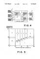
- FIGS. 5 and 7are views illustrating an example of a three-dimensional map.
- FIG. 6is a flowchart for describing the flow of driving force distribution processing.
- a vehicle velocity sensor 1a detector 2 for detecting amount of battery charge, an accelerator opening sensor 3, a traveling mode deciding unit 4, a throttle opening deciding unit 5, a data output deciding unit 6, an engine throttle motor controller 7, and a wheel drive motor controller 8.
- the traveling mode deciding unit 4, throttle opening deciding unit 5 and data output deciding unit 6indicate the functional construction of the control circuit 20 of FIG. 2 in block form.
- the traveling mode deciding unit 4has a three-dimensional map comprising vehicle velocity, accelerator opening and amount of battery charge. Driving force distribution (the decision of traveling mode) is performed based on the map.
- the throttle opening deciding unit 5illustrates an example of a three-dimensional map, specifically the relationship between accelerator opening and amount of battery charge at vehicle velocities below 40 km/h (the dashed line indicates a velocity of 37 km/h).
- the numerals 1, 2, 3, . . . in the mapindicate traveling modes.
- the throttle opening deciding unit 5possesses a table in which throttle openings (engine output distribution values) corresponding to accelerator openings are registered.
- the deciding unit 5selects a table depending upon the traveling mode and, by referring to the selected table, decides the throttle opening which corresponds to the accelerator opening.
- the engine throttle motor controller 7is controlled in accordance with the throttle opening.
- the data output deciding unit 6also has a table for each traveling mode, each table having registered data outputs corresponding to throttle openings.
- the deciding unit 6selects a table depending upon the traveling mode and, by referring to the selected table, decides the data output which corresponds to the accelerator opening.
- the wheel drive motor controller 8is controlled in accordance with the motor output value.
- FIGS. 5 and 7illustrate three-dimension data maps useable in the present invention.
- Numeral 1 in FIG. 5denotes a traveling mode involving solely the motor, in which distribution of output conforming to the amount of charge is performed as indicated in the following table:
- Numerals 2 through 7 in FIG. 5denote hybrid traveling modes, in which maximum output conforming to each amount of charge is distributed as motor output, with 0-100% being apportioned to engine output.
- Numeral 8denotes a charging mode, and 9 an engine traveling mode.
- Numeral 7denotes an engine traveling mode in which maximum vehicle velocity of the motor is exceeded.
- the maximum vehicle velocity of the motoris the vehicle velocity obtained when the rotational speed of the motor has reached the maximum allowable speed of the motor. In other words, since regenerative braking acts when maximum vehicle velocity of the motor is exceeded, in this mode the motor drive system is placed in neutral and the vehicle travels under the driving force solely of the engine.
- throttle opening and motor outputare decided in accordance with the various modes and accelerator openings using the map and tables. Moreover, the maximum amount of motor output is varied in accordance with the amount of battery charge; when the amount of battery charge decreases, the output of the motor is reduced. When the amount of battery charge falls below a predetermined amount, the charging mode is established at a small accelerator opening and the engine traveling mode is established at a large accelerator opening.
- initial settingsare made at a step 1, after which detection signals indicative of accelerator opening, vehicle velocity and remaining life of the battery are inputted at steps 2, 3 and 4.
- the traveling modeis decided by referring to the three-dimensional map at a step 5.
- a step 6at which throttle opening corresponding to accelerator opening is decided by referring to the engine output distribution table on the basis of the decided traveling mode
- a step 7at which motor output value corresponding to accelerator opening is decided by referring to the motor output distribution table on the basis of the decided traveling mode.
- output control of the engine throttle motor and wheel drive motoris executed based upon the decided values.
- motor outputis set finely in accordance with the amount of battery charge so that battery service life can be prolonged per charge.
- stable vehicle travelis assured since sudden fluctuations in driving force are prevented from occurring.
Landscapes
- Engineering & Computer Science (AREA)
- Chemical & Material Sciences (AREA)
- Combustion & Propulsion (AREA)
- Transportation (AREA)
- Mechanical Engineering (AREA)
- Automation & Control Theory (AREA)
- Life Sciences & Earth Sciences (AREA)
- Sustainable Development (AREA)
- Sustainable Energy (AREA)
- Power Engineering (AREA)
- Electric Propulsion And Braking For Vehicles (AREA)
- Hybrid Electric Vehicles (AREA)
Abstract
Description
This application is a continuation of application Ser. No. 07/277,119 filed Nov. 29, 1988, now abandoned.
This invention relates to a driving force distribution system in a hybrid vehicle of the type in which the front or rear set of wheels is driven by an engine and the other set of wheels is driven by a motor. The distribution system is adapted to changeover the distribution of driving force based on the amount of charge remaining in a battery.
There have been various proposals relating to four-wheel drive hybrid vehicles in which the front or rear set of wheels is driven by an engine and the other set of wheels is driven by motors. The applicant has also made a number of such proposals. According to one such proposal (see Japanese Patent Application No. 62-37183), the distribution of driving force to the front and rear wheels is performed based on accelerator opening, vehicle velocity and shift lever position, and the distributed values are revised based on the amount of battery charge. The proposal as disclosed in the previous application will now be described.
FIG. 1 is a view illustrating an example of the control system configuration of a hybrid vehicle, FIG. 2 is a block diagram showing an example of the construction of a control circuit, and FIG. 3 is a view illustrating the relationship between the amount of battery charge and various detected values. Shown are anengine 11,controllers battery 13, adetector 14 for detecting the amount of battery charging (the amount of remaining battery life), acomputer 15 for control,motor input interface 21, aCPU 22, aROM 23, aRAM 24, and anoutput interface 25.
As shown in FIG. 1, theengine 11 drives the front wheels of the vehicle and themotors battery 13 is used as the power supply for themotors detector 14 detects the amount of charge in thebattery 13 based on the battery voltage or current, the concentration of the battery electrolyte or the specific gravity of the electrolyte. The output signal of thedetector 14 is applied to thecontrol computer 15. As shown in FIG. 2, thecontrol computer 15 includes theCPU 22, theROM 23, theRAM 24, theinput interface 21 and theoutput interface 25 and is adapted to set vehicle driving force based on accelerator opening, vehicle velocity, shift lever position and the like, as well as the front and rear wheel torque distribution values based on load where each of the front and rear wheels contact the ground, this in turn being based upon the load distribution of the vehicle. The torque distribution values are outputted to thecontrollers motors engine 11 increased correspondingly if the amount of battery charge is small. Theengine controller 12 controls engine torque by controlling throttle opening or the amount of fuel injection in accordance with the torque distribution value. Themotor controller 16 controls motor torque by controlling the current which flows through the motors in accordance with the torque distribution value.
The specific gravity and concentration of the electrolyte and the battery voltage vary depending upon the amount of charge, as shown in FIG. 3. As in conventional vehicles, means for ascertaining the amount of battery charge include an ammeter for detecting charging/discharging current, a voltmeter for detecting battery voltage, and a battery charge lamp which provides a warning indication when battery voltage falls below a reference value, The driver operates the vehicle while determining the amount of battery charge by observing these instruments. Thedetector 14 detects the amount of battery charge from battery voltage or current or from the concentration or specific gravity of the electrolyte basically in the same manner as the abovementioned instruments.
With this hybrid vehicle driving force distribution system arranged as described above, motor and engine outputs are adjusted by thecontrol computer 15 so as to lower motor output and reduce power consumption when it is determined that there is a small amount of charge inbattery 13. In other words, control is such that motor driving force is reduced by decreasing motor output while engine output is raised correspondingly. The end result is that overall driving force of the vehicle does not change.
However, with this hybrid vehicle driving force distribution system, the amount of battery charge can be determined in terms of only three stages, namely high, medium and low. A problem which arises as a result of this is that when the amount of charge changes, driving force distribution suddenly changes and therefore the vehicle cannot travel in a stable manner.
Another problem is that since there is no charging mode, the battery cannot be charged automatically when there is a decrease in the amount of battery charge. As a result, nothing can be done to check consumption of the battery.
Accordingly, an object of the present invention is to provide a driving force distribution system in which the output of a driving motor in a hybrid vehicle can be finely set in dependence upon the amount of charge in a power supply.
Another object of the present invention is to provide a driving force distribution system in which the service life of a battery is prolonged.
Still another object of the present invention is to provide a driving force distribution system in which the distribution of driving force is suitably performed to stabilize vehicle travel by eliminating sudden fluctuations in driving force.
According to the present invention, the foregoing objects are attained by providing a driving force distribution system in a hybrid vehicle in which the front or rear set of wheels is driven by an engine and the other set of wheels is driven by a motor, characterized by having a table for deciding engine throttle opening and motor output from amount of battery charge, vehicle velocity and accelerator opening, with driving force being distributed in accordance with engine throttle opening and motor output decided upon referring to the table.
In accordance with the above arrangement, engine throttle opening and motor output are set in the table in dependence upon the values of the amount of battery charge, vehicle velocity and accelerator opening, thereby making it possible to change driving force finely in dependence upon vehicle traveling conditions, such as velocity, and the amount of battery charge. As a result, driving force can be distributed without a sudden change in the driving force.
Still other objects and advantages of the invention will in part be obvious and will in part be apparent from the specification.
The invention accordingly comprises the features of construction, combinations of elements and arrangement of parts which will be exemplified in the construction hereinafter set forth, and the scope of the invention will be indicated in the claims.
FIG. 1 is a view showing the control system configuration of a hybrid vehicle;
FIG. 2 is a block diagram showing an example of the construction of a control circuit;
FIG. 3 is a view illustrating the relationship between the amount of battery charge and various detected values;
FIG. 4 is a view illustrating the construction of an embodiment of a hybrid vehicle control system according to the present invention;
FIGS. 5 and 7 are views illustrating an example of a three-dimensional map; and
FIG. 6 is a flowchart for describing the flow of driving force distribution processing.
An embodiment of the present invention will now be described with reference to the drawings.
With reference to FIG. 4, there is shown avehicle velocity sensor 1, adetector 2 for detecting amount of battery charge, anaccelerator opening sensor 3, a travelingmode deciding unit 4, a throttleopening deciding unit 5, a dataoutput deciding unit 6, an enginethrottle motor controller 7, and a wheeldrive motor controller 8. The travelingmode deciding unit 4, throttleopening deciding unit 5 and dataoutput deciding unit 6 indicate the functional construction of thecontrol circuit 20 of FIG. 2 in block form. The travelingmode deciding unit 4 has a three-dimensional map comprising vehicle velocity, accelerator opening and amount of battery charge. Driving force distribution (the decision of traveling mode) is performed based on the map. FIG. 5 illustrates an example of a three-dimensional map, specifically the relationship between accelerator opening and amount of battery charge at vehicle velocities below 40 km/h (the dashed line indicates a velocity of 37 km/h). Thenumerals opening deciding unit 5 possesses a table in which throttle openings (engine output distribution values) corresponding to accelerator openings are registered. The decidingunit 5 selects a table depending upon the traveling mode and, by referring to the selected table, decides the throttle opening which corresponds to the accelerator opening. The enginethrottle motor controller 7 is controlled in accordance with the throttle opening. The dataoutput deciding unit 6 also has a table for each traveling mode, each table having registered data outputs corresponding to throttle openings. The decidingunit 6 selects a table depending upon the traveling mode and, by referring to the selected table, decides the data output which corresponds to the accelerator opening. The wheeldrive motor controller 8 is controlled in accordance with the motor output value.
In FIGS. 5 and 7 illustrate three-dimension data maps useable in the present invention. Numeral 1 in FIG. 5 denotes a traveling mode involving solely the motor, in which distribution of output conforming to the amount of charge is performed as indicated in the following table:
______________________________________ Amount of Charge (%) 25-35 35-45 45-55 Maximum Output (%) 50 60 70 Amount of Charge (%) 55-65 65-75 75-100 Maximum Output (%) 80 90 100 ______________________________________
In the hybrid vehicle driving force distribution system of the present invention, throttle opening and motor output are decided in accordance with the various modes and accelerator openings using the map and tables. Moreover, the maximum amount of motor output is varied in accordance with the amount of battery charge; when the amount of battery charge decreases, the output of the motor is reduced. When the amount of battery charge falls below a predetermined amount, the charging mode is established at a small accelerator opening and the engine traveling mode is established at a large accelerator opening.
The flow of driving force distribution processing will now be described with reference to the flowchart of FIG. 6.
First, initial settings are made at astep 1, after which detection signals indicative of accelerator opening, vehicle velocity and remaining life of the battery are inputted atsteps step 5. This is followed by astep 6, at which throttle opening corresponding to accelerator opening is decided by referring to the engine output distribution table on the basis of the decided traveling mode, and then astep 7, at which motor output value corresponding to accelerator opening is decided by referring to the motor output distribution table on the basis of the decided traveling mode. Finally, output control of the engine throttle motor and wheel drive motor is executed based upon the decided values.
Thus, in accordance with the present invention as described above, motor output is set finely in accordance with the amount of battery charge so that battery service life can be prolonged per charge. In addition, stable vehicle travel is assured since sudden fluctuations in driving force are prevented from occurring.
As many apparently widely different embodiments of the present invention can be made without departing from the spirit and scope thereof, it is to be understood that the invention is not limited to the specific embodiments thereof except as defined in the appended claims.
Claims (3)
1. A hybrid vehicle comprising:
front and rear sets of wheels;
an internal combustion engine for driving one set of said first and second sets of wheels;
an electric motor for driving the other set of said first and second sets of wheels;
a battery for supplying power to said electric motor;
an accelerator opening sensor for detecting the degree of accelerator opening;
a battery charge amount detector for detecting the amount of battery charge of said battery;
travelling mode deciding means for selecting a travelling mode by comparing the detected degree of accelerator opening and the detected amount of battery charge with predetermined values for degree of accelerator opening and amount of battery charge provided as a map correlating said predetermined values with a plurality of travelling modes;
throttle opening setting means for controlling the output of said engine by selecting an engine output distribution table corresponding to the selected travelling mode from among a plurality of engine output distribution tables providing predetermined values for throttle opening correlated with predetermined values for accelerator opening, for selecting a throttle opening value corresponding to the detected accelerator opening from said selected engine output distribution table and for setting the throttle opening in accordance with the selected throttle opening value; and
motor output setting means for controlling the output of said motor by selecting a motor output distribution table corresponding to the selected travelling mode from among a plurality of motor output distribution tables providing predetermined motor output values correlated with predetermined values for accelerator opening, for selecting a motor output value corresponding to the detected accelerator opening from said selected motor output distribution table and for setting the motor output in accordance with the selected motor output value.
2. A hybrid vehicle according to claim 1, wherein said plurality of travelling modes comprises:
a first, battery charging mode selected responsive to detection of an amount of battery charge less than a threshold amount; and
at least a second travelling mode, selected responsive to detection of an amount of battery charge exceeding said threshold amount, wherein said motor output is decreased as the detected amount of battery charge decreases.
3. A hybrid vehicle according to claim 1 further comprising a speed sensor for detecting actual vehicle speed, wherein said map is a three-dimensional map correlating said predetermined map values for degree of accelerator opening and battery charge with plural predetermined map values for vehicle speed, and wherein a travelling mode is selected by comparing detected vehicle speed, detected battery charge and detected degree of accelerator opening with said predetermined map values.
Priority Applications (1)
| Application Number | Priority Date | Filing Date | Title |
|---|---|---|---|
| US07/560,268US5176213A (en) | 1987-12-09 | 1990-07-31 | Driving force distribution system for hybrid vehicles |
Applications Claiming Priority (4)
| Application Number | Priority Date | Filing Date | Title |
|---|---|---|---|
| JP62-313049 | 1987-12-09 | ||
| JP62313049AJP2598437B2 (en) | 1987-12-09 | 1987-12-09 | Hybrid vehicle |
| US27711988A | 1988-11-29 | 1988-11-29 | |
| US07/560,268US5176213A (en) | 1987-12-09 | 1990-07-31 | Driving force distribution system for hybrid vehicles |
Related Parent Applications (1)
| Application Number | Title | Priority Date | Filing Date |
|---|---|---|---|
| US27711988AContinuation | 1987-12-09 | 1988-11-29 |
Publications (1)
| Publication Number | Publication Date |
|---|---|
| US5176213Atrue US5176213A (en) | 1993-01-05 |
Family
ID=27339289
Family Applications (1)
| Application Number | Title | Priority Date | Filing Date |
|---|---|---|---|
| US07/560,268Expired - LifetimeUS5176213A (en) | 1987-12-09 | 1990-07-31 | Driving force distribution system for hybrid vehicles |
Country Status (1)
| Country | Link |
|---|---|
| US (1) | US5176213A (en) |
Cited By (67)
| Publication number | Priority date | Publication date | Assignee | Title |
|---|---|---|---|---|
| US5367455A (en)* | 1991-08-02 | 1994-11-22 | Honda Giken Kogyo Kabushiki Kaisha | Running performance control apparatus and method for an electric vehicle |
| US5495906A (en)* | 1993-01-25 | 1996-03-05 | Toyota Jidosha Kabushiki Kaisha | Controller of hybrid electric vehicle |
| US5557181A (en)* | 1992-09-18 | 1996-09-17 | Hitachi, Ltd. | Brake control apparatus for electric motor vehicle |
| US5650931A (en)* | 1994-02-21 | 1997-07-22 | Toyota Jidosha Kabushiki Kaisha | Generator output controller for electric vehicle with mounted generator |
| US5664635A (en)* | 1994-05-18 | 1997-09-09 | Mitsubishi Jidosha Kogyo Kabushiki Kaisha | Control system for inhibiting unintended use of hybrid electric vehicle |
| US5667029A (en)* | 1995-05-31 | 1997-09-16 | New York Institute Of Technology | Drive system for hybrid electric vehicle |
| US5697466A (en)* | 1992-11-12 | 1997-12-16 | Kabushikikaisha Equos Research | Hybrid vehicle |
| US5704440A (en)* | 1995-05-31 | 1998-01-06 | New York Institute Of Technology | Energy distribution method for hydrid electric vehicle |
| US5734099A (en)* | 1995-12-28 | 1998-03-31 | Yazaki Corporation | Potential travel distance estimation system for electric automobiles |
| US5778326A (en)* | 1994-10-25 | 1998-07-07 | Kabushikikaisha Equos Research | Hybrid vehicle with battery charge control relative to a driving route |
| US5786640A (en)* | 1995-02-13 | 1998-07-28 | Nippon Soken, Inc. | Generator control system for a hybrid vehicle driven by an electric motor and an internal combustion engine |
| US5815824A (en)* | 1995-03-06 | 1998-09-29 | Mitsubishi Jidosha Kogyo Kabushiki Kaisha | Navigation system for electric automobile |
| US5820172A (en)* | 1997-02-27 | 1998-10-13 | Ford Global Technologies, Inc. | Method for controlling energy flow in a hybrid electric vehicle |
| EP0829389A3 (en)* | 1996-09-17 | 1998-10-14 | Toyota Jidosha Kabushiki Kaisha | Power output apparatus and method of controlling the same |
| US5841201A (en)* | 1996-02-29 | 1998-11-24 | Toyota Jidosha Kabushiki Kaisha | Hybrid vehicle drive system having a drive mode using both engine and electric motor |
| US5935040A (en)* | 1996-07-23 | 1999-08-10 | Toyota Jidosha Kabushiki Kaisha | Hybrid vehicle drive system adapted to produce substantially constant vehicle drive force under the same vehicle running condition, even in different modes of operation |
| US5939794A (en)* | 1995-07-25 | 1999-08-17 | Nippon Soken, Inc. | Engine control system for hybrid vehicle |
| US5960897A (en)* | 1996-08-29 | 1999-10-05 | Honda Giken Kogyo Kabushiki Kaisha | Auxiliary vehicle driving system |
| US5999864A (en)* | 1997-04-23 | 1999-12-07 | Chrysler Corporation | Method of power management for a hybrid powertrain system |
| US6209672B1 (en) | 1998-09-14 | 2001-04-03 | Paice Corporation | Hybrid vehicle |
| US6338391B1 (en) | 1999-03-01 | 2002-01-15 | Paice Corporation | Hybrid vehicles incorporating turbochargers |
| US6349782B1 (en)* | 1999-05-12 | 2002-02-26 | Honda Giken Kogyo Kabushiki Kaisha | Front-and-rear wheel drive vehicle |
| US6367570B1 (en) | 1997-10-17 | 2002-04-09 | Electromotive Inc. | Hybrid electric vehicle with electric motor providing strategic power assist to load balance internal combustion engine |
| US6394208B1 (en) | 2000-03-30 | 2002-05-28 | Ford Global Technologies, Inc. | Starter/alternator control strategy to enhance driveability of a low storage requirement hybrid electric vehicle |
| US20030037977A1 (en)* | 2001-08-27 | 2003-02-27 | Honda Giken Kogyo Kabushiki Kaisha | Drive force distribution apparatus for hybrid vehicle |
| US6554088B2 (en) | 1998-09-14 | 2003-04-29 | Paice Corporation | Hybrid vehicles |
| US6741917B2 (en)* | 2001-02-05 | 2004-05-25 | Nissan Motor Co., Ltd. | Hybrid vehicle control apparatus |
| US20040178635A1 (en)* | 2003-03-10 | 2004-09-16 | Government Of United States Of America | Methods of operating a parallel hybrid vehicle |
| US6876098B1 (en) | 2003-09-25 | 2005-04-05 | The United States Of America As Represented By The Administrator Of The Environmental Protection Agency | Methods of operating a series hybrid vehicle |
| EP1564518A1 (en)* | 2004-02-11 | 2005-08-17 | Rheinmetall Landsysteme GmbH | Vehicle with land mine protection |
| US20050257679A1 (en)* | 2004-02-11 | 2005-11-24 | Rheinmetall Landsysteme Gmbh | Mine protection vehicle system |
| US20060009884A1 (en)* | 2004-07-06 | 2006-01-12 | Nissan Motor Co., Ltd. | Hybrid vehicle control system |
| US7013205B1 (en)* | 2004-11-22 | 2006-03-14 | International Business Machines Corporation | System and method for minimizing energy consumption in hybrid vehicles |
| US20060060397A1 (en)* | 2002-12-07 | 2006-03-23 | Claus Bischoff | Method for setting the operating point of a drive train |
| US20060185917A1 (en)* | 2005-02-22 | 2006-08-24 | Honda Motor Co., Ltd. | Control mechanism and display for hybrid vehicle |
| US7240748B2 (en)* | 2002-09-20 | 2007-07-10 | Honda Giken Kogyo Kabushiki Kaisha | Hybrid vehicle |
| US20070187161A1 (en)* | 2006-02-15 | 2007-08-16 | Tatsuo Kiuchi | Control system for a hybrid electric vehicle |
| US20070193808A1 (en)* | 2006-02-21 | 2007-08-23 | Ford Global Technologies, Llc | System and method for managing a powertrain in a vehicle |
| US7290627B1 (en)* | 1992-04-13 | 2007-11-06 | Conrad Oliver Gardner | Extended range motor vehicle having ambient pollutant processing |
| US20080215201A1 (en)* | 2006-10-11 | 2008-09-04 | Ford Global Technologies, Llc | Method for Controlling a Hybrid Electric Vehicle Powertrain with Divided Power Flow Paths |
| US20090114463A1 (en)* | 2007-06-12 | 2009-05-07 | Devault Robert C | Self-learning control system for plug-in hybrid vehicles |
| US20090321166A1 (en)* | 2006-03-21 | 2009-12-31 | Jens-Werner Falkenstein | Method for operating a hybrid drive for a vehicle |
| US20100063704A1 (en)* | 2008-09-05 | 2010-03-11 | Ford Global Technologies, Llc | Hybrid electric vehicle powertrain with enhanced reverse drive performance |
| US20100108417A1 (en)* | 2008-10-31 | 2010-05-06 | Curt Douglas Gilmore | Parallel power supplies for hev applications |
| US20100250075A1 (en)* | 2009-03-25 | 2010-09-30 | Aisin Aw Co., Ltd. | Vehicle control device and vehicle drive system |
| US20100280736A1 (en)* | 2006-02-24 | 2010-11-04 | Robert Bosch Gmbh | Method for Operating a Hybrid Vehicle and Control Unit for Implementing the Method |
| US20100304923A1 (en)* | 2006-10-23 | 2010-12-02 | Robert Bosch Gmbh | Method For Controlling A Hybrid Drive |
| US20110172865A1 (en)* | 2010-06-10 | 2011-07-14 | Ford Global Technologies, Llc | Method For Optimizing Powertrain Efficiency For A Vehicle |
| EP2397385A1 (en)* | 2010-06-16 | 2011-12-21 | Altra S.P.A. | Method for controlling a parallel hybrid driving system for a vehicle equiped with a manual transmission and corresponding driving system |
| EP2397355A1 (en)* | 2010-06-16 | 2011-12-21 | Altra S.P.A. | Control method for a parallel hybrid traction system for a vehicle with an automatic transmission |
| CN102781702A (en)* | 2010-01-28 | 2012-11-14 | 标致·雪铁龙汽车公司 | Method for providing a preventive drive system for a hybrid vehicle |
| US20130311028A1 (en)* | 2011-02-09 | 2013-11-21 | Suzuki Motor Corporation | Driving source control device for hybrid motor vehicle and driving source control method for hybrid motor vehicle and hybrid motor vehicle |
| US8751084B2 (en) | 2012-05-08 | 2014-06-10 | Curtis Instruments, Inc. | Vehicle component recognition and adjustment for energy efficiency |
| US20150046011A1 (en)* | 2012-03-26 | 2015-02-12 | Toyota Jidosha Kabushiki Kaisha | Vehicle control device |
| DE10049567B4 (en)* | 1999-10-08 | 2017-12-14 | Toyota Jidosha Kabushiki Kaisha | Vehicle control unit for controlling a four-wheel drive motor vehicle |
| US10882399B2 (en) | 2005-11-17 | 2021-01-05 | Invently Automotive Inc. | Electric vehicle power management system |
| US11180025B2 (en) | 2005-11-17 | 2021-11-23 | Invently Automotive Inc. | Electric vehicle power management system |
| US11186173B2 (en) | 2005-11-17 | 2021-11-30 | Invently Automotive Inc. | Electric vehicle power management system |
| US11214144B2 (en) | 2005-11-17 | 2022-01-04 | Invently Automotive Inc. | Electric vehicle power management system |
| US11230190B2 (en) | 2005-11-17 | 2022-01-25 | Invently Automotive Inc. | Electric vehicle power management system |
| US11247564B2 (en) | 2005-11-17 | 2022-02-15 | Invently Automotive Inc. | Electric vehicle power management system |
| US11254211B2 (en) | 2005-11-17 | 2022-02-22 | Invently Automotive Inc. | Electric vehicle power management system |
| US11267338B2 (en) | 2005-11-17 | 2022-03-08 | Invently Automotive Inc. | Electric vehicle power management system |
| US11279233B2 (en) | 2005-11-17 | 2022-03-22 | Invently Automotive Inc. | Electric vehicle power management system |
| US11345236B2 (en) | 2005-11-17 | 2022-05-31 | Invently Automotive Inc. | Electric vehicle power management system |
| US11370302B2 (en) | 2005-11-17 | 2022-06-28 | Invently Automotive Inc. | Electric vehicle power management system |
| US11390165B2 (en) | 2005-11-17 | 2022-07-19 | Invently Automotive Inc. | Electric vehicle power management system |
Citations (11)
| Publication number | Priority date | Publication date | Assignee | Title |
|---|---|---|---|---|
| US3503464A (en)* | 1968-03-04 | 1970-03-31 | Michel N Yardney | Control system for a battery and hydrocarbon powered vehicle |
| US3623568A (en)* | 1968-05-31 | 1971-11-30 | Nissan Motor | Electromechanical power train system for an automotive vehicle |
| US4180138A (en)* | 1977-09-30 | 1979-12-25 | Dana Corporation | Vehicle having auxiliary drive mechanism |
| US4305254A (en)* | 1980-02-20 | 1981-12-15 | Daihatsu Motor Co., Ltd. | Control apparatus and method for engine/electric hybrid vehicle |
| JPS5869403A (en)* | 1981-10-20 | 1983-04-25 | Daihatsu Motor Co Ltd | Hybrid car control device |
| US4438342A (en)* | 1980-05-15 | 1984-03-20 | Kenyon Keith E | Novel hybrid electric vehicle |
| US4533011A (en)* | 1979-10-27 | 1985-08-06 | Volkswagenwerk Aktiengesellschaft | Hybrid drive for a vehicle, in particular an automobile |
| US4562894A (en)* | 1982-02-03 | 1986-01-07 | Yang Tai Her | Coupling multi driving system |
| US4697660A (en)* | 1985-10-31 | 1987-10-06 | Wu C H | Vehicle with multiple power source |
| US4923025A (en)* | 1985-10-21 | 1990-05-08 | Ellers Clarence W | Hybrid electric/ice vehicle drive system |
| US4926329A (en)* | 1986-03-11 | 1990-05-15 | Dr. Ing. H.C.F. Porsche Ag | Arrangement for controlling the power transmission of an all-wheel drive vehicle |
- 1990
- 1990-07-31USUS07/560,268patent/US5176213A/ennot_activeExpired - Lifetime
Patent Citations (11)
| Publication number | Priority date | Publication date | Assignee | Title |
|---|---|---|---|---|
| US3503464A (en)* | 1968-03-04 | 1970-03-31 | Michel N Yardney | Control system for a battery and hydrocarbon powered vehicle |
| US3623568A (en)* | 1968-05-31 | 1971-11-30 | Nissan Motor | Electromechanical power train system for an automotive vehicle |
| US4180138A (en)* | 1977-09-30 | 1979-12-25 | Dana Corporation | Vehicle having auxiliary drive mechanism |
| US4533011A (en)* | 1979-10-27 | 1985-08-06 | Volkswagenwerk Aktiengesellschaft | Hybrid drive for a vehicle, in particular an automobile |
| US4305254A (en)* | 1980-02-20 | 1981-12-15 | Daihatsu Motor Co., Ltd. | Control apparatus and method for engine/electric hybrid vehicle |
| US4438342A (en)* | 1980-05-15 | 1984-03-20 | Kenyon Keith E | Novel hybrid electric vehicle |
| JPS5869403A (en)* | 1981-10-20 | 1983-04-25 | Daihatsu Motor Co Ltd | Hybrid car control device |
| US4562894A (en)* | 1982-02-03 | 1986-01-07 | Yang Tai Her | Coupling multi driving system |
| US4923025A (en)* | 1985-10-21 | 1990-05-08 | Ellers Clarence W | Hybrid electric/ice vehicle drive system |
| US4697660A (en)* | 1985-10-31 | 1987-10-06 | Wu C H | Vehicle with multiple power source |
| US4926329A (en)* | 1986-03-11 | 1990-05-15 | Dr. Ing. H.C.F. Porsche Ag | Arrangement for controlling the power transmission of an all-wheel drive vehicle |
Cited By (101)
| Publication number | Priority date | Publication date | Assignee | Title |
|---|---|---|---|---|
| US5367455A (en)* | 1991-08-02 | 1994-11-22 | Honda Giken Kogyo Kabushiki Kaisha | Running performance control apparatus and method for an electric vehicle |
| US7290627B1 (en)* | 1992-04-13 | 2007-11-06 | Conrad Oliver Gardner | Extended range motor vehicle having ambient pollutant processing |
| US5557181A (en)* | 1992-09-18 | 1996-09-17 | Hitachi, Ltd. | Brake control apparatus for electric motor vehicle |
| US5697466A (en)* | 1992-11-12 | 1997-12-16 | Kabushikikaisha Equos Research | Hybrid vehicle |
| US5495906A (en)* | 1993-01-25 | 1996-03-05 | Toyota Jidosha Kabushiki Kaisha | Controller of hybrid electric vehicle |
| US5650931A (en)* | 1994-02-21 | 1997-07-22 | Toyota Jidosha Kabushiki Kaisha | Generator output controller for electric vehicle with mounted generator |
| US5664635A (en)* | 1994-05-18 | 1997-09-09 | Mitsubishi Jidosha Kogyo Kabushiki Kaisha | Control system for inhibiting unintended use of hybrid electric vehicle |
| US5778326A (en)* | 1994-10-25 | 1998-07-07 | Kabushikikaisha Equos Research | Hybrid vehicle with battery charge control relative to a driving route |
| US5832396A (en)* | 1994-10-25 | 1998-11-03 | Kabushikikaisha Equos Research | Hybrid vehicle including means for maintaining residual charge capacity based on destination information |
| US5786640A (en)* | 1995-02-13 | 1998-07-28 | Nippon Soken, Inc. | Generator control system for a hybrid vehicle driven by an electric motor and an internal combustion engine |
| US5815824A (en)* | 1995-03-06 | 1998-09-29 | Mitsubishi Jidosha Kogyo Kabushiki Kaisha | Navigation system for electric automobile |
| US5704440A (en)* | 1995-05-31 | 1998-01-06 | New York Institute Of Technology | Energy distribution method for hydrid electric vehicle |
| US5667029A (en)* | 1995-05-31 | 1997-09-16 | New York Institute Of Technology | Drive system for hybrid electric vehicle |
| US5939794A (en)* | 1995-07-25 | 1999-08-17 | Nippon Soken, Inc. | Engine control system for hybrid vehicle |
| US5734099A (en)* | 1995-12-28 | 1998-03-31 | Yazaki Corporation | Potential travel distance estimation system for electric automobiles |
| US5841201A (en)* | 1996-02-29 | 1998-11-24 | Toyota Jidosha Kabushiki Kaisha | Hybrid vehicle drive system having a drive mode using both engine and electric motor |
| US5935040A (en)* | 1996-07-23 | 1999-08-10 | Toyota Jidosha Kabushiki Kaisha | Hybrid vehicle drive system adapted to produce substantially constant vehicle drive force under the same vehicle running condition, even in different modes of operation |
| US5960897A (en)* | 1996-08-29 | 1999-10-05 | Honda Giken Kogyo Kabushiki Kaisha | Auxiliary vehicle driving system |
| US6166449A (en)* | 1996-09-17 | 2000-12-26 | Toyota Jidosha Kabushiki Kaisha | Power output apparatus having a battery with a high charge-discharge efficiency |
| EP0829389A3 (en)* | 1996-09-17 | 1998-10-14 | Toyota Jidosha Kabushiki Kaisha | Power output apparatus and method of controlling the same |
| US5820172A (en)* | 1997-02-27 | 1998-10-13 | Ford Global Technologies, Inc. | Method for controlling energy flow in a hybrid electric vehicle |
| US5999864A (en)* | 1997-04-23 | 1999-12-07 | Chrysler Corporation | Method of power management for a hybrid powertrain system |
| US6367570B1 (en) | 1997-10-17 | 2002-04-09 | Electromotive Inc. | Hybrid electric vehicle with electric motor providing strategic power assist to load balance internal combustion engine |
| US6209672B1 (en) | 1998-09-14 | 2001-04-03 | Paice Corporation | Hybrid vehicle |
| US6554088B2 (en) | 1998-09-14 | 2003-04-29 | Paice Corporation | Hybrid vehicles |
| US20030217876A1 (en)* | 1998-09-14 | 2003-11-27 | Paice Corporation | Hybrid vehicles |
| US7597164B2 (en) | 1998-09-14 | 2009-10-06 | Paice Llc | Hybrid vehicles |
| US7520353B2 (en) | 1998-09-14 | 2009-04-21 | Paice Llc | Hybrid vehicle configuration |
| US7455134B2 (en) | 1998-09-14 | 2008-11-25 | Paice Llc | Hybrid vehicles |
| US7392871B2 (en) | 1998-09-14 | 2008-07-01 | Paice Llc | Hybrid vehicles |
| US7104347B2 (en) | 1998-09-14 | 2006-09-12 | Paice Llc | Hybrid vehicles |
| US7237634B2 (en) | 1998-09-14 | 2007-07-03 | Paice Llc | Hybrid vehicles |
| US6338391B1 (en) | 1999-03-01 | 2002-01-15 | Paice Corporation | Hybrid vehicles incorporating turbochargers |
| US6349782B1 (en)* | 1999-05-12 | 2002-02-26 | Honda Giken Kogyo Kabushiki Kaisha | Front-and-rear wheel drive vehicle |
| DE10049567B4 (en)* | 1999-10-08 | 2017-12-14 | Toyota Jidosha Kabushiki Kaisha | Vehicle control unit for controlling a four-wheel drive motor vehicle |
| US6394208B1 (en) | 2000-03-30 | 2002-05-28 | Ford Global Technologies, Inc. | Starter/alternator control strategy to enhance driveability of a low storage requirement hybrid electric vehicle |
| US6741917B2 (en)* | 2001-02-05 | 2004-05-25 | Nissan Motor Co., Ltd. | Hybrid vehicle control apparatus |
| US20030037977A1 (en)* | 2001-08-27 | 2003-02-27 | Honda Giken Kogyo Kabushiki Kaisha | Drive force distribution apparatus for hybrid vehicle |
| US6704627B2 (en)* | 2001-08-27 | 2004-03-09 | Honda Giken Kogyo Kabushiki Kaisha | Drive force distribution apparatus for hybrid vehicle |
| US7240748B2 (en)* | 2002-09-20 | 2007-07-10 | Honda Giken Kogyo Kabushiki Kaisha | Hybrid vehicle |
| US20060060397A1 (en)* | 2002-12-07 | 2006-03-23 | Claus Bischoff | Method for setting the operating point of a drive train |
| US6998727B2 (en) | 2003-03-10 | 2006-02-14 | The United States Of America As Represented By The Administrator Of The Environmental Protection Agency | Methods of operating a parallel hybrid vehicle having an internal combustion engine and a secondary power source |
| US20040178635A1 (en)* | 2003-03-10 | 2004-09-16 | Government Of United States Of America | Methods of operating a parallel hybrid vehicle |
| US7857082B2 (en) | 2003-09-25 | 2010-12-28 | The United States Of America, As Represented By The Administrator Of The U.S. Environmental Protection Agency | Methods of operating a series hybrid vehicle |
| US20050145425A1 (en)* | 2003-09-25 | 2005-07-07 | Govt. Of The U.S.A. As Represented By The Admi. Of The U.S. Environmental Protection Agency | Methods of operating a series hybrid vehicle |
| US20050145426A1 (en)* | 2003-09-25 | 2005-07-07 | GOV. of the U.S.A. as represented by the Administrator of the U.S. environmental protection | Methods of operating a series hybrid vehicle |
| US7456509B2 (en) | 2003-09-25 | 2008-11-25 | The United States Of America As Represented By The Administrator Of The U.S. Environmental Protection Agency | Methods of operating a series hybrid vehicle |
| US8381851B2 (en) | 2003-09-25 | 2013-02-26 | The United States Of America, As Represented By The Administrator Of The U.S. Environmental Protection Agency | Methods of operating a series hybrid vehicle |
| US6876098B1 (en) | 2003-09-25 | 2005-04-05 | The United States Of America As Represented By The Administrator Of The Environmental Protection Agency | Methods of operating a series hybrid vehicle |
| US7594561B2 (en) | 2004-02-11 | 2009-09-29 | Rheinmetall Landsysteme Gmbh | Mine protection vehicle system |
| US20050284682A1 (en)* | 2004-02-11 | 2005-12-29 | Rheinmetall Landsysteme Gmbh | Vehicle protection against the effect of a land mine |
| US7228927B2 (en) | 2004-02-11 | 2007-06-12 | Rheinmetall Landsysteme Gmbh | Vehicle protection against the effect of a land mine |
| EP1564518A1 (en)* | 2004-02-11 | 2005-08-17 | Rheinmetall Landsysteme GmbH | Vehicle with land mine protection |
| US20050257679A1 (en)* | 2004-02-11 | 2005-11-24 | Rheinmetall Landsysteme Gmbh | Mine protection vehicle system |
| EP1614574A3 (en)* | 2004-07-06 | 2007-07-04 | Nissan Motor Co., Ltd. | Hybrid vehicle control system |
| US7693637B2 (en) | 2004-07-06 | 2010-04-06 | Nissan Motor Co., Ltd. | Hybrid vehicle control system |
| US20060009884A1 (en)* | 2004-07-06 | 2006-01-12 | Nissan Motor Co., Ltd. | Hybrid vehicle control system |
| US7013205B1 (en)* | 2004-11-22 | 2006-03-14 | International Business Machines Corporation | System and method for minimizing energy consumption in hybrid vehicles |
| US7617894B2 (en)* | 2005-02-22 | 2009-11-17 | Honda Motor Co., Ltd. | Control mechanism and display for hybrid vehicle |
| US20060185917A1 (en)* | 2005-02-22 | 2006-08-24 | Honda Motor Co., Ltd. | Control mechanism and display for hybrid vehicle |
| US11390165B2 (en) | 2005-11-17 | 2022-07-19 | Invently Automotive Inc. | Electric vehicle power management system |
| US11186173B2 (en) | 2005-11-17 | 2021-11-30 | Invently Automotive Inc. | Electric vehicle power management system |
| US11370302B2 (en) | 2005-11-17 | 2022-06-28 | Invently Automotive Inc. | Electric vehicle power management system |
| US10882399B2 (en) | 2005-11-17 | 2021-01-05 | Invently Automotive Inc. | Electric vehicle power management system |
| US11345236B2 (en) | 2005-11-17 | 2022-05-31 | Invently Automotive Inc. | Electric vehicle power management system |
| US11279233B2 (en) | 2005-11-17 | 2022-03-22 | Invently Automotive Inc. | Electric vehicle power management system |
| US11247564B2 (en) | 2005-11-17 | 2022-02-15 | Invently Automotive Inc. | Electric vehicle power management system |
| US11180025B2 (en) | 2005-11-17 | 2021-11-23 | Invently Automotive Inc. | Electric vehicle power management system |
| US11230190B2 (en) | 2005-11-17 | 2022-01-25 | Invently Automotive Inc. | Electric vehicle power management system |
| US11267338B2 (en) | 2005-11-17 | 2022-03-08 | Invently Automotive Inc. | Electric vehicle power management system |
| US11254211B2 (en) | 2005-11-17 | 2022-02-22 | Invently Automotive Inc. | Electric vehicle power management system |
| US11214144B2 (en) | 2005-11-17 | 2022-01-04 | Invently Automotive Inc. | Electric vehicle power management system |
| US20070187161A1 (en)* | 2006-02-15 | 2007-08-16 | Tatsuo Kiuchi | Control system for a hybrid electric vehicle |
| US7810593B2 (en)* | 2006-02-15 | 2010-10-12 | Mitsubishi Fuso Truck And Bus Corporation | Control system for a hybrid electric vehicle |
| US7870925B2 (en)* | 2006-02-21 | 2011-01-18 | Ford Global Technologies, Llc | System and method for managing a powertrain in a vehicle |
| US20070193808A1 (en)* | 2006-02-21 | 2007-08-23 | Ford Global Technologies, Llc | System and method for managing a powertrain in a vehicle |
| US20100280736A1 (en)* | 2006-02-24 | 2010-11-04 | Robert Bosch Gmbh | Method for Operating a Hybrid Vehicle and Control Unit for Implementing the Method |
| US8919467B2 (en)* | 2006-02-24 | 2014-12-30 | Robert Bosch Gmbh | Method for operating a hybrid vehicle and control unit for implementing the method |
| US20090321166A1 (en)* | 2006-03-21 | 2009-12-31 | Jens-Werner Falkenstein | Method for operating a hybrid drive for a vehicle |
| US7576501B2 (en) | 2006-10-11 | 2009-08-18 | Ford Global Technologies, Llc | Method for controlling a hybrid electric vehicle powertrain with divided power flow paths |
| US20080215201A1 (en)* | 2006-10-11 | 2008-09-04 | Ford Global Technologies, Llc | Method for Controlling a Hybrid Electric Vehicle Powertrain with Divided Power Flow Paths |
| US20100304923A1 (en)* | 2006-10-23 | 2010-12-02 | Robert Bosch Gmbh | Method For Controlling A Hybrid Drive |
| US8529399B2 (en)* | 2006-10-23 | 2013-09-10 | Robert Bosch Gmbh | Method for controlling a hybrid drive |
| US20090114463A1 (en)* | 2007-06-12 | 2009-05-07 | Devault Robert C | Self-learning control system for plug-in hybrid vehicles |
| US7849944B2 (en) | 2007-06-12 | 2010-12-14 | Ut-Battelle, Llc | Self-learning control system for plug-in hybrid vehicles |
| US20100063704A1 (en)* | 2008-09-05 | 2010-03-11 | Ford Global Technologies, Llc | Hybrid electric vehicle powertrain with enhanced reverse drive performance |
| US9545839B2 (en) | 2008-09-05 | 2017-01-17 | Ford Global Technologies, Llc | Hybrid electric vehicle powertrain with enhanced reverse drive performance |
| US20100108417A1 (en)* | 2008-10-31 | 2010-05-06 | Curt Douglas Gilmore | Parallel power supplies for hev applications |
| US8280599B2 (en)* | 2009-03-25 | 2012-10-02 | Aisin Aw Co., Ltd. | Vehicle control device and vehicle drive system for implementing a one-way transmission speed or engaging a first engaging element in an idle stop state |
| US20100250075A1 (en)* | 2009-03-25 | 2010-09-30 | Aisin Aw Co., Ltd. | Vehicle control device and vehicle drive system |
| CN102781702A (en)* | 2010-01-28 | 2012-11-14 | 标致·雪铁龙汽车公司 | Method for providing a preventive drive system for a hybrid vehicle |
| CN102781702B (en)* | 2010-01-28 | 2016-01-13 | 标致·雪铁龙汽车公司 | The preventative driving method of motor vehicle driven by mixed power |
| US8103397B2 (en)* | 2010-06-10 | 2012-01-24 | Ford Global Technologies, Llc | Method for optimizing powertrain efficiency for a vehicle |
| US20110172865A1 (en)* | 2010-06-10 | 2011-07-14 | Ford Global Technologies, Llc | Method For Optimizing Powertrain Efficiency For A Vehicle |
| EP2397355A1 (en)* | 2010-06-16 | 2011-12-21 | Altra S.P.A. | Control method for a parallel hybrid traction system for a vehicle with an automatic transmission |
| EP2397385A1 (en)* | 2010-06-16 | 2011-12-21 | Altra S.P.A. | Method for controlling a parallel hybrid driving system for a vehicle equiped with a manual transmission and corresponding driving system |
| DE112011104861B4 (en) | 2011-02-09 | 2021-12-09 | Suzuki Motor Corporation | Power source control device for hybrid automobile and power source control method for hybrid automobile and hybrid automobile |
| US20130311028A1 (en)* | 2011-02-09 | 2013-11-21 | Suzuki Motor Corporation | Driving source control device for hybrid motor vehicle and driving source control method for hybrid motor vehicle and hybrid motor vehicle |
| US9457795B2 (en)* | 2012-03-26 | 2016-10-04 | Toyota Jidosha Kabushiki Kaisha | Vehicle control device |
| US20150046011A1 (en)* | 2012-03-26 | 2015-02-12 | Toyota Jidosha Kabushiki Kaisha | Vehicle control device |
| US8751084B2 (en) | 2012-05-08 | 2014-06-10 | Curtis Instruments, Inc. | Vehicle component recognition and adjustment for energy efficiency |
Similar Documents
| Publication | Publication Date | Title |
|---|---|---|
| US5176213A (en) | Driving force distribution system for hybrid vehicles | |
| EP1966019B1 (en) | Hybrid vehicle and control method thereof | |
| US5969624A (en) | Battery charge control system for a hybrid vehicle driven by an electric motor and an internal combustion engine | |
| US7374000B2 (en) | Electric generating system for automobiles and its control method | |
| CN114312345A (en) | Dynamic and smooth compensation distribution control method for front and rear axle torques of four-wheel-drive pure electric vehicle | |
| US20020107618A1 (en) | Control device and control method for hybrid vehicle | |
| US10029669B2 (en) | Powertrain and method of coordinating chassis and propulsion system torque limits | |
| CN114559925B (en) | A four-wheel drive control method for a multi-motor plug-in hybrid electric vehicle | |
| US11951842B2 (en) | Electrified vehicle configured to selectively deactivate restricted power mode based on acceleration request | |
| EP1008483B1 (en) | Control system for a hybrid vehicle | |
| US5365431A (en) | Control of electric vehicle motors responsive to detected vehicle speed and required total driving force | |
| CN113002321A (en) | New energy automobile braking method and device, whole automobile controller and new energy automobile | |
| US6971461B2 (en) | Front and rear wheel drive vehicle and control device for controlling same | |
| JP3376918B2 (en) | Constant-speed cruise control system for vehicles | |
| US7328096B2 (en) | Driving force switching control apparatus | |
| US20020058564A1 (en) | Front and rear wheel drive vehicle and control device for controlling same | |
| US12122404B2 (en) | Vehicle and acceleration limit control method therefor | |
| CN112026775A (en) | Vehicle four-wheel drive control method and electronic equipment | |
| JP2000166105A (en) | Battery charge state control device | |
| US7605561B2 (en) | Method for controlling charging of a power source of a hybrid vehicle | |
| JPH09242579A (en) | Motor control device | |
| JP2598437B2 (en) | Hybrid vehicle | |
| CN108725428A (en) | Method and device for controlling torque of front wheel and rear wheel of hybrid electric vehicle | |
| CN114801778B (en) | Braking control method and device of electric automobile and electric automobile | |
| JPH11125129A (en) | Vehicle |
Legal Events
| Date | Code | Title | Description |
|---|---|---|---|
| FEPP | Fee payment procedure | Free format text:PAYOR NUMBER ASSIGNED (ORIGINAL EVENT CODE: ASPN); ENTITY STATUS OF PATENT OWNER: LARGE ENTITY | |
| STCF | Information on status: patent grant | Free format text:PATENTED CASE | |
| CC | Certificate of correction | ||
| FPAY | Fee payment | Year of fee payment:4 | |
| FPAY | Fee payment | Year of fee payment:8 | |
| FPAY | Fee payment | Year of fee payment:12 |