US5174349A - Power table saw assemblies having integral spare part storage - Google Patents
Power table saw assemblies having integral spare part storageDownload PDFInfo
- Publication number
- US5174349A US5174349AUS07/743,085US74308591AUS5174349AUS 5174349 AUS5174349 AUS 5174349AUS 74308591 AUS74308591 AUS 74308591AUS 5174349 AUS5174349 AUS 5174349A
- Authority
- US
- United States
- Prior art keywords
- housing
- work surface
- power table
- table saw
- spare parts
- Prior art date
- Legal status (The legal status is an assumption and is not a legal conclusion. Google has not performed a legal analysis and makes no representation as to the accuracy of the status listed.)
- Expired - Fee Related
Links
- 230000000712assemblyEffects0.000titledescription7
- 238000000429assemblyMethods0.000titledescription7
- NJPPVKZQTLUDBO-UHFFFAOYSA-NnovaluronChemical compoundC1=C(Cl)C(OC(F)(F)C(OC(F)(F)F)F)=CC=C1NC(=O)NC(=O)C1=C(F)C=CC=C1FNJPPVKZQTLUDBO-UHFFFAOYSA-N0.000claimsdescription7
- 210000001364upper extremityAnatomy0.000claimsdescription7
- 230000014759maintenance of locationEffects0.000claimsdescription5
- 210000003141lower extremityAnatomy0.000claimsdescription4
- 238000004891communicationMethods0.000claimsdescription3
- 230000013011matingEffects0.000claimsdescription2
- 230000003116impacting effectEffects0.000abstract1
- 238000010276constructionMethods0.000description3
- 230000007246mechanismEffects0.000description2
- 230000002452interceptive effectEffects0.000description1
- 238000012423maintenanceMethods0.000description1
- 238000000034methodMethods0.000description1
Images


Classifications
- B—PERFORMING OPERATIONS; TRANSPORTING
- B23—MACHINE TOOLS; METAL-WORKING NOT OTHERWISE PROVIDED FOR
- B23D—PLANING; SLOTTING; SHEARING; BROACHING; SAWING; FILING; SCRAPING; LIKE OPERATIONS FOR WORKING METAL BY REMOVING MATERIAL, NOT OTHERWISE PROVIDED FOR
- B23D47/00—Sawing machines or sawing devices working with circular saw blades, characterised only by constructional features of particular parts
- B23D47/02—Sawing machines or sawing devices working with circular saw blades, characterised only by constructional features of particular parts of frames; of guiding arrangements for work-table or saw-carrier
- B23D47/025—Sawing machines or sawing devices working with circular saw blades, characterised only by constructional features of particular parts of frames; of guiding arrangements for work-table or saw-carrier of tables
- B—PERFORMING OPERATIONS; TRANSPORTING
- B25—HAND TOOLS; PORTABLE POWER-DRIVEN TOOLS; MANIPULATORS
- B25H—WORKSHOP EQUIPMENT, e.g. FOR MARKING-OUT WORK; STORAGE MEANS FOR WORKSHOPS
- B25H1/00—Work benches; Portable stands or supports for positioning portable tools or work to be operated on thereby
- B25H1/12—Work benches; Portable stands or supports for positioning portable tools or work to be operated on thereby with storage compartments
- Y—GENERAL TAGGING OF NEW TECHNOLOGICAL DEVELOPMENTS; GENERAL TAGGING OF CROSS-SECTIONAL TECHNOLOGIES SPANNING OVER SEVERAL SECTIONS OF THE IPC; TECHNICAL SUBJECTS COVERED BY FORMER USPC CROSS-REFERENCE ART COLLECTIONS [XRACs] AND DIGESTS
- Y10—TECHNICAL SUBJECTS COVERED BY FORMER USPC
- Y10T—TECHNICAL SUBJECTS COVERED BY FORMER US CLASSIFICATION
- Y10T83/00—Cutting
- Y10T83/768—Rotatable disc tool pair or tool and carrier
- Y10T83/7684—With means to support work relative to tool[s]
- Y10T83/773—Work-support includes passageway for tool [e.g., slotted table]
Definitions
- This inventionrelates generally to power table saws and, more particularly, to power table saw assemblies constructed to enable storage of spare parts at convenient locations about the surface of the assemblies for ready access thereto.
- the inventionconsists of a table saw assembly having a storage system arranged in an aesthetically pleasing manner about its surface for accommodating spare parts in engagement with the assembly in a manner such that the spare parts will not become disengaged from the device while being stored. Furthermore, the spare parts are stored in convenient locations integral with the assembly in order to provide easy access to these spare parts for purposes of enabling access to the parts as needed. In view of the provision of this storage system, tool change time is minimized and the effective operation of the device is maximized.
- the inventive table saw assembliesinclude a pedestal arrangement for storage of a rip fence when it is not in use on the work surface of the saw as well as a nesting arrangement for storing a miter guide in a horizontal position and, in addition, a vertically positioned blade wrench socket for storing a blade wrench for use with the device.
- Each of the storage areasis positioned about the surface of the table saw device in a manner such that the stored part does not interfere with the operation of the device, but each of the spare parts stored is readily accessible and in immediate proximity to its area of use.
- a specific object of this inventionis to provide a table saw assembly having a storage system for nestingly and securely accommodating spare parts for use in the saw assembly positioned about the surface of the assembly.
- a more specific objectis to provide such storage system for accommodating a miter guide and a rip fence for use in operation of the saw and a blade wrench for use in operation and maintenance of the saws.
- FIG. 1shows a perspective view of a table saw of the present invention
- FIG. 2is a top plan view of a housing of the table saw of FIG. 1 showing the storage system employed for accommodating a rip fence, a miter guide and a blade wrench;
- FIG. 2Ais an enlarged fragmentary side view of a pedestal arrangement for accommodating a rip fence
- FIGS. 3 and 4are fragmentary top plan views showing alternative embodiments of the pedestal arrangement for accommodating the rip fence
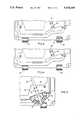
- FIG. 5is an enlarged fragmentary top plan view showing a miter guide being inserted into a storage arrangement positioned beneath the work surface of the table saw of FIG. 1;
- FIG. 6is an enlarged fragmentary top plan view showing the miter guide stored within the storage arrangement
- FIG. 7is a partial sectional view of the miter guide stored within the arrangement of FIG. 6;
- FIG. 8is an enlarged top view showing a blade wrench stored in the housing of the table saw of FIG. 1 seated in a slot in the upper work surface of the saw;
- FIG. 9is a side elevational view showing an inset formed in the housing of the table saw of FIG. 1 and in communication with the slot illustrated in FIG. 8 to accommodate a handle of the stored blade wrench.
- FIG. 1generally illustrates a power table saw 10 including a housing 12 having spaced front and rear walls 14 and 16, respectively, sealingly interconnected by spaced side walls 18 and 20.
- the housing 12sealingly engages and supports a slotted, substantially planar work surface 22 on the upper extremity of said walls.
- a circular saw blade or cutting member 24is mounted for rotation on a rotatable shaft 26 within the housing beneath the planar work surface via conventional bearing means (not shown) driven by a standard drive motor (not shown).
- the blade 24is positioned transverse to the front and rear walls 14 and 16 of the housing 12.
- the upper periphery 28 of the saw blade 24projects outwardly from the interior of the housing 12 through a slot 30 in the slotted work surface 22 to engage a workpiece which may be positioned on the work surface.
- the table saw 10further incorporates the usual mechanisms (not shown) enabling the saw blade 24 and its supporting shaft (not shown) to be raised and lowered vertically and to be tilted angularly relative to the work surface 22 for controlled cutting of the material to be sawed.
- a plurality of storage arrangementsPositioned about the surface of the housing 12 are a plurality of storage arrangements (designated generally as 32, 34 and 36) to accommodate spare parts for use in conjunction with the operation of the power table saw 10.
- the spare partsare thus stored in a manner which renders them readily accessible but at locations about the surface of the housing 12 in which they do not interfere with the operation of said saw blade 24.
- the storage arrangement 32includes a pair of pedestals 38 and 40, respectively, which extend outwardly from a lower extremity 42 of side wall 18.
- the pedestals 38 and 40are aligned in relationship to one another so that spaced sections 44 and 46 of a rip fence assembly 48 can be engagingly accommodated by each of the pedestals 38 and 40.
- the rip fence 48will then extend in a generally horizontal plane between the pedestals 38 and 40 when it is stored therein.
- FIG. 2Abest illustrates the configuration of the pedestals as exemplified by the pedestal 38 having tab 50 projecting upwardly therefrom.
- FIG. 3illustrates a further alternative embodiment wherein neither of the pedestals 38 and 40 have tabs but the pedestals are configured to engagingly and nestingly accommodate the rip fence 48 when positioned therein and therebetween.
- Storage arrangement 34includes a horizontally extending flange section 58 projecting inwardly from the upper extremity 60 of wall 18.
- the flange section 58has a channel 62 formed in an upper face 64 thereof to accommodate a portion 65 of a miter guide 66 in nesting relationship between the flange section 58 of housing 12 and the underside 68 of working surface 22.
- a recess or niche 70is formed in flange section 58 which extends vertically downward from the channel 6 to accommodate another portion 71 of the miter guide 66.
- the slot 70terminates at its lower extremity 72 in a ledge 74 on which a further portion 75 of the miter guide 66 rests when the miter guide is stored in the channel 62 and the recess 70.
- the miter guide 66in order to store the miter guide 66, it is slid under the upper work surface 22 as illustrated in FIG. 5 with the rule edge portion 65 advancing into the channel 62 in housing 12. In this manner the miter guide 66 is sandwiched between the underside 68 of the work surface 22 and the upper extremity 60 of wall 18 in order to nestingly store the miter guide. If additional retention is desired to maintain the stored miter guide 66 in position, retention members or straps 67 may be provided lateral to the channel 62 as illustrated in phantom in FIG. 6.
- Storage arrangement 36includes a slot 76 illustrated in FIG. 8 formed in the planar working surface 22 which is in communication with a downwardly extending vertical inset 78 in side wall 20 of the housing 12 so that a blade wrench 80 can be inserted through the slot 76 in the working surface 22 with its head 82 projecting outwardly therefrom and the handle 84 of the wrench 80 is accommodated within the vertical inset 78.
- a retention element 86in the nature of a strap or other like member may be positioned lateral to the vertical inset 78 in order to provide a positive lock or holding mechanism for the wrench handle 84 extending through slot 76 and into position within the vertical inset 78, which acts as a "holster” for accommodating the handle 84.
- the present inventionprovides an improved storage system for retaining valuable spare parts in ready position for retrieval without damaging the aesthetics or functionality of the product.
- the present devicesand, particularly, the relative placement of the storage arrangements about the surface of the power table saw assembly as well as the configuration and structure of the various storage arrangements, a more efficient and effective device is provided relative to prior power table saw assemblies.
Landscapes
- Engineering & Computer Science (AREA)
- Mechanical Engineering (AREA)
- Sawing (AREA)
Abstract
Description
Claims (7)
Priority Applications (6)
| Application Number | Priority Date | Filing Date | Title |
|---|---|---|---|
| US07/743,085US5174349A (en) | 1991-08-09 | 1991-08-09 | Power table saw assemblies having integral spare part storage |
| AU20859/92AAU651714B2 (en) | 1991-08-09 | 1992-08-06 | Power table saw assemblies having integral spare part storage |
| CA 2075676CA2075676C (en) | 1991-08-09 | 1992-08-10 | Power table saw assemblies having integral spare part storage |
| JP21300792AJPH05200623A (en) | 1991-08-09 | 1992-08-10 | Power table saw assembly |
| AU65943/94AAU659577B2 (en) | 1991-08-09 | 1994-06-24 | Power table saw assemblies having integral spare part storage |
| AU65944/94AAU665491B2 (en) | 1991-08-09 | 1994-06-24 | Power table saw assemblies having integral spare part storage |
Applications Claiming Priority (1)
| Application Number | Priority Date | Filing Date | Title |
|---|---|---|---|
| US07/743,085US5174349A (en) | 1991-08-09 | 1991-08-09 | Power table saw assemblies having integral spare part storage |
Publications (1)
| Publication Number | Publication Date |
|---|---|
| US5174349Atrue US5174349A (en) | 1992-12-29 |
Family
ID=24987460
Family Applications (1)
| Application Number | Title | Priority Date | Filing Date |
|---|---|---|---|
| US07/743,085Expired - Fee RelatedUS5174349A (en) | 1991-08-09 | 1991-08-09 | Power table saw assemblies having integral spare part storage |
Country Status (4)
| Country | Link |
|---|---|
| US (1) | US5174349A (en) |
| JP (1) | JPH05200623A (en) |
| AU (3) | AU651714B2 (en) |
| CA (1) | CA2075676C (en) |
Cited By (80)
| Publication number | Priority date | Publication date | Assignee | Title |
|---|---|---|---|---|
| US5619896A (en)* | 1995-06-27 | 1997-04-15 | Chen; Ruey Z. | Base of a sawing machine |
| US5653273A (en)* | 1995-08-14 | 1997-08-05 | Bach; Emin Nelson | Universal precision woodworking center |
| US5863052A (en)* | 1994-10-27 | 1999-01-26 | Roman; Gregory S. | Collapsible carpentry work station and push cart combination |
| US5979523A (en)* | 1996-09-20 | 1999-11-09 | Black & Decker Inc. | Table saw |
| USD422290S (en)* | 1999-04-13 | 2000-04-04 | Black & Decker Inc. | Table saw |
| USD425529S (en)* | 1999-08-11 | 2000-05-23 | S-B Power Tool Company | Table saw |
| USD437605S1 (en) | 2000-01-31 | 2001-02-13 | Emerson Electric Co. | Jobsite table saw |
| US6244149B1 (en)* | 1996-06-17 | 2001-06-12 | Black & Decker Inc. | Blade and motor carrier with height/angle adjustment mechanism |
| USD458947S1 (en) | 2001-09-28 | 2002-06-18 | S-B Power Tool Company | Table saw |
| US6539831B2 (en)* | 2001-05-23 | 2003-04-01 | Durq Machinery Corp. | Circular power saw |
| US20030079592A1 (en)* | 2001-10-25 | 2003-05-01 | Jackie Lee | Apparatus for clamping a workpiece-blocking plate of a table saw |
| US6736042B2 (en) | 2001-03-01 | 2004-05-18 | Porter-Cable Corporation | Work piece guiding system for a table saw |
| US6763695B1 (en)* | 2002-10-30 | 2004-07-20 | J-Dan, Inc. | Sheet material cutter and cut-off gauge for use in combination with a sheet bending brake |
| US20040187666A1 (en)* | 2003-03-25 | 2004-09-30 | Durq Machinery Corp. | Table saw |
| US6857345B2 (en) | 2000-08-14 | 2005-02-22 | Sd3, Llc | Brake positioning system |
| US6877410B2 (en) | 2000-09-29 | 2005-04-12 | Sd3, Llc | Miter saw with improved safety system |
| US20050092155A1 (en)* | 2003-09-17 | 2005-05-05 | Phillips William J. | Power tool and components therefor |
| US6899004B1 (en)* | 1998-08-14 | 2005-05-31 | Delta International Machinery Corp. | Sawing apparatus and saw fence system |
| US6920814B2 (en) | 2000-08-14 | 2005-07-26 | Sd3, Llc | Cutting tool safety system |
| US6945149B2 (en) | 2001-07-25 | 2005-09-20 | Sd3, Llc | Actuators for use in fast-acting safety systems |
| US20050241973A1 (en)* | 2004-05-03 | 2005-11-03 | Nomis, Llc | Work center/clamping table and storage system |
| USD513272S1 (en)* | 2004-05-14 | 2005-12-27 | Wmh Tool Group, Inc. | Table saw base and panels |
| USD514604S1 (en)* | 1999-04-13 | 2006-02-07 | Black & Decker Inc. | Portions of a table saw |
| US6997090B2 (en) | 2001-08-13 | 2006-02-14 | Sd3, Llc | Safety systems for power equipment |
| US7024975B2 (en) | 2000-08-14 | 2006-04-11 | Sd3, Llc | Brake mechanism for power equipment |
| US7055417B1 (en) | 1999-10-01 | 2006-06-06 | Sd3, Llc | Safety system for power equipment |
| US7100483B2 (en) | 2000-08-14 | 2006-09-05 | Sd3, Llc | Firing subsystem for use in a fast-acting safety system |
| US7137326B2 (en) | 2000-08-14 | 2006-11-21 | Sd3, Llc | Translation stop for use in power equipment |
| US7171879B2 (en) | 2001-07-02 | 2007-02-06 | Sd3, Llc | Discrete proximity detection system |
| US20070029012A1 (en)* | 2005-08-02 | 2007-02-08 | Durq Machinery Corp. | Work table having means for holding the detached table extension in place |
| USD537853S1 (en)* | 2005-04-14 | 2007-03-06 | Durq Machinery Corp. | Table saw |
| US7210383B2 (en) | 2000-08-14 | 2007-05-01 | Sd3, Llc | Detection system for power equipment |
| US7225712B2 (en) | 2000-08-14 | 2007-06-05 | Sd3, Llc | Motion detecting system for use in a safety system for power equipment |
| USD545330S1 (en)* | 2006-10-30 | 2007-06-26 | Black & Decker Inc. | Table saw |
| US7284467B2 (en) | 2000-08-14 | 2007-10-23 | Sd3, Llc | Apparatus and method for detecting dangerous conditions in power equipment |
| US7290472B2 (en) | 2002-01-14 | 2007-11-06 | Sd3, Llc | Miter saw with improved safety system |
| US7308843B2 (en) | 2000-08-14 | 2007-12-18 | Sd3, Llc | Spring-biased brake mechanism for power equipment |
| US7347851B1 (en) | 2004-03-09 | 2008-03-25 | Leo B Kriksunov | Needleless hypodermic jet injector apparatus and method |
| US7350444B2 (en) | 2000-08-14 | 2008-04-01 | Sd3, Llc | Table saw with improved safety system |
| US7350445B2 (en) | 2003-08-20 | 2008-04-01 | Sd3, Llc | Brake cartridge for power equipment |
| US7353737B2 (en) | 2001-08-13 | 2008-04-08 | Sd3, Llc | Miter saw with improved safety system |
| US7357056B2 (en) | 2000-09-29 | 2008-04-15 | Sd3, Llc | Cutting tool safety system |
| US7359174B2 (en) | 2000-08-14 | 2008-04-15 | Sd3, Llc | Motion detecting system for use in a safety system for power equipment |
| US7421315B2 (en) | 2001-11-13 | 2008-09-02 | Sd3, Llc | Detection system for power equipment |
| US7472634B2 (en) | 2003-08-20 | 2009-01-06 | Sd3, Llc | Woodworking machines with overmolded arbors |
| US7481140B2 (en) | 2005-04-15 | 2009-01-27 | Sd3, Llc | Detection systems for power equipment |
| US7509899B2 (en) | 2000-08-14 | 2009-03-31 | Sd3, Llc | Retraction system for use in power equipment |
| US7536238B2 (en) | 2003-12-31 | 2009-05-19 | Sd3, Llc | Detection systems for power equipment |
| US7600455B2 (en) | 2000-08-14 | 2009-10-13 | Sd3, Llc | Logic control for fast-acting safety system |
| US7621205B2 (en) | 1999-10-01 | 2009-11-24 | Sd3, Llc | Band saw with safety system |
| US7707920B2 (en) | 2003-12-31 | 2010-05-04 | Sd3, Llc | Table saws with safety systems |
| US20100107841A1 (en)* | 2008-10-31 | 2010-05-06 | Durq Machinery Corp. | Worktable of a table saw |
| US7712403B2 (en) | 2001-07-03 | 2010-05-11 | Sd3, Llc | Actuators for use in fast-acting safety systems |
| US7784507B2 (en) | 2000-09-29 | 2010-08-31 | Sd3, Llc | Router with improved safety system |
| USD626158S1 (en)* | 2009-01-28 | 2010-10-26 | David Jebb | Table saw |
| US20100269656A1 (en)* | 2009-04-28 | 2010-10-28 | Credo Technology Corporation | Table saw with symmetrical rail fence storage capability |
| US7827890B2 (en) | 2004-01-29 | 2010-11-09 | Sd3, Llc | Table saws with safety systems and systems to mount and index attachments |
| US7836804B2 (en) | 2003-08-20 | 2010-11-23 | Sd3, Llc | Woodworking machines with overmolded arbors |
| USD636417S1 (en) | 2010-07-26 | 2011-04-19 | Robert Bosch Tool Corporation | Support assembly for a table saw |
| US8004664B2 (en)* | 2002-04-18 | 2011-08-23 | Chang Type Industrial Company | Power tool control system |
| US8065943B2 (en) | 2000-09-18 | 2011-11-29 | Sd3, Llc | Translation stop for use in power equipment |
| US8082826B2 (en) | 2008-03-25 | 2011-12-27 | Power Tool Institute | Saw accessories and clamp for use therewith |
| US8091456B2 (en) | 2008-03-25 | 2012-01-10 | Power Tool Institute | Safety devices for saws |
| US8100039B2 (en) | 2000-08-14 | 2012-01-24 | Sd3, Llc | Miter saw with safety system |
| US8186255B2 (en) | 2000-09-29 | 2012-05-29 | Sd3, Llc | Contact detection system for power equipment |
| USD663328S1 (en) | 2011-11-04 | 2012-07-10 | Robert Bosch Gmbh | Table saw |
| US8459157B2 (en) | 2003-12-31 | 2013-06-11 | Sd3, Llc | Brake cartridges and mounting systems for brake cartridges |
| US8616104B2 (en) | 2010-07-12 | 2013-12-31 | Robert Bosch Gmbh | Portable table saw |
| US20150174756A1 (en)* | 2013-05-02 | 2015-06-25 | Power Box Ag | Apparatus for use with power tools |
| US9333638B2 (en) | 2012-11-30 | 2016-05-10 | Robert Bosch Gmbh | Power tool including an anti-tilt structure for an accessory |
| US9724840B2 (en) | 1999-10-01 | 2017-08-08 | Sd3, Llc | Safety systems for power equipment |
| US20180015555A1 (en)* | 2006-04-21 | 2018-01-18 | Black & Decker Inc. | Table Saw |
| US9975233B2 (en) | 2012-11-30 | 2018-05-22 | Nanjing Chervon Industry Co., Ltd. | Power tool including an accessory |
| US10092968B2 (en) | 2013-11-01 | 2018-10-09 | Sawstop Holding Llc | Table saws |
| US10118308B2 (en) | 2013-10-17 | 2018-11-06 | Sawstop Holding Llc | Systems to mount and index riving knives and spreaders in table saws |
| US10442106B2 (en) | 2014-03-31 | 2019-10-15 | Sawstop Holding Llc | Extension rails for table saws |
| US20200102762A1 (en)* | 2018-09-27 | 2020-04-02 | Terex South Dakota, Inc. | Positioner for mobile work platforms |
| US10792834B2 (en) | 2017-06-05 | 2020-10-06 | Milwaukee Electric Tool Corporation | Table saw |
| US10933554B2 (en) | 2017-05-25 | 2021-03-02 | Sawstop Holding Llc | Power saws |
| EP4106953A4 (en)* | 2020-02-18 | 2024-03-27 | Shaper Tools, Inc. | SYSTEM AND WORKSTATION FOR PERFORMING A TASK ON A WORKPIECE |
Citations (6)
| Publication number | Priority date | Publication date | Assignee | Title |
|---|---|---|---|---|
| US2759507A (en)* | 1953-12-15 | 1956-08-21 | Portable Electric Tools Inc | Combination carrying case and saw table |
| US4239195A (en)* | 1979-07-02 | 1980-12-16 | Waterloo Industries, Inc. | Workbench |
| US4378828A (en)* | 1981-04-06 | 1983-04-05 | Stanley Zilka | Combined collapsible workbench and removable tool carrier |
| US4599927A (en)* | 1985-05-08 | 1986-07-15 | Emerson Electric Co. | Tool elevation and bevel adjustment for direct drive power tool |
| US5082038A (en)* | 1990-12-11 | 1992-01-21 | Teel Jeff A | Door fabrication station |
| US5113920A (en)* | 1990-10-03 | 1992-05-19 | Svein Sedeniussen | Workbench, particularly for doors |
Family Cites Families (2)
| Publication number | Priority date | Publication date | Assignee | Title |
|---|---|---|---|---|
| US4549455A (en)* | 1981-12-02 | 1985-10-29 | Perilloux Jr Milton | Combination table saw |
| US4516612A (en)* | 1982-09-03 | 1985-05-14 | Wiley Edward R | Multipurpose table saw |
- 1991
- 1991-08-09USUS07/743,085patent/US5174349A/ennot_activeExpired - Fee Related
- 1992
- 1992-08-06AUAU20859/92Apatent/AU651714B2/ennot_activeCeased
- 1992-08-10CACA 2075676patent/CA2075676C/ennot_activeExpired - Fee Related
- 1992-08-10JPJP21300792Apatent/JPH05200623A/enactivePending
- 1994
- 1994-06-24AUAU65943/94Apatent/AU659577B2/ennot_activeCeased
- 1994-06-24AUAU65944/94Apatent/AU665491B2/ennot_activeCeased
Patent Citations (6)
| Publication number | Priority date | Publication date | Assignee | Title |
|---|---|---|---|---|
| US2759507A (en)* | 1953-12-15 | 1956-08-21 | Portable Electric Tools Inc | Combination carrying case and saw table |
| US4239195A (en)* | 1979-07-02 | 1980-12-16 | Waterloo Industries, Inc. | Workbench |
| US4378828A (en)* | 1981-04-06 | 1983-04-05 | Stanley Zilka | Combined collapsible workbench and removable tool carrier |
| US4599927A (en)* | 1985-05-08 | 1986-07-15 | Emerson Electric Co. | Tool elevation and bevel adjustment for direct drive power tool |
| US5113920A (en)* | 1990-10-03 | 1992-05-19 | Svein Sedeniussen | Workbench, particularly for doors |
| US5082038A (en)* | 1990-12-11 | 1992-01-21 | Teel Jeff A | Door fabrication station |
Cited By (132)
| Publication number | Priority date | Publication date | Assignee | Title |
|---|---|---|---|---|
| US5863052A (en)* | 1994-10-27 | 1999-01-26 | Roman; Gregory S. | Collapsible carpentry work station and push cart combination |
| US5619896A (en)* | 1995-06-27 | 1997-04-15 | Chen; Ruey Z. | Base of a sawing machine |
| US5653273A (en)* | 1995-08-14 | 1997-08-05 | Bach; Emin Nelson | Universal precision woodworking center |
| US6244149B1 (en)* | 1996-06-17 | 2001-06-12 | Black & Decker Inc. | Blade and motor carrier with height/angle adjustment mechanism |
| US6595096B2 (en) | 1996-06-17 | 2003-07-22 | Black & Decker Inc. | Blade and motor carrier with height/angle adjustment mechanism |
| US6820524B1 (en) | 1996-06-17 | 2004-11-23 | Black & Decker Inc. | Blade and motor carrier with height/angle adjustment mechanism |
| US6453786B1 (en) | 1996-06-17 | 2002-09-24 | Black & Decker Inc. | Blade and motor carrier with height/angle adjustment mechanism |
| US6131629A (en)* | 1996-09-20 | 2000-10-17 | Black & Decker Inc. | Table saw |
| US5979523A (en)* | 1996-09-20 | 1999-11-09 | Black & Decker Inc. | Table saw |
| US6899004B1 (en)* | 1998-08-14 | 2005-05-31 | Delta International Machinery Corp. | Sawing apparatus and saw fence system |
| US7594459B2 (en) | 1998-08-14 | 2009-09-29 | Delta International Machinery Corp. | Sawing apparatus with debris collection system and accessory shelf |
| USD514604S1 (en)* | 1999-04-13 | 2006-02-07 | Black & Decker Inc. | Portions of a table saw |
| USD422290S (en)* | 1999-04-13 | 2000-04-04 | Black & Decker Inc. | Table saw |
| USD425529S (en)* | 1999-08-11 | 2000-05-23 | S-B Power Tool Company | Table saw |
| US9522476B2 (en) | 1999-10-01 | 2016-12-20 | Sd3, Llc | Power equipment with detection and reaction systems |
| US7895927B2 (en) | 1999-10-01 | 2011-03-01 | Sd3, Llc | Power equipment with detection and reaction systems |
| US7525055B2 (en) | 1999-10-01 | 2009-04-28 | Sd3, Llc | Switch box for power tools with safety systems |
| US8196499B2 (en) | 1999-10-01 | 2012-06-12 | Sd3, Llc | Power equipment with detection and reaction systems |
| US7788999B2 (en) | 1999-10-01 | 2010-09-07 | Sd3, Llc | Brake mechanism for power equipment |
| US8408106B2 (en) | 1999-10-01 | 2013-04-02 | Sd3, Llc | Method of operating power equipment with detection and reaction systems |
| US7347131B2 (en) | 1999-10-01 | 2008-03-25 | Sd3, Llc | Miter saw with improved safety system |
| US7621205B2 (en) | 1999-10-01 | 2009-11-24 | Sd3, Llc | Band saw with safety system |
| US9724840B2 (en) | 1999-10-01 | 2017-08-08 | Sd3, Llc | Safety systems for power equipment |
| US9969014B2 (en) | 1999-10-01 | 2018-05-15 | Sawstop Holding Llc | Power equipment with detection and reaction systems |
| US9925683B2 (en) | 1999-10-01 | 2018-03-27 | Sawstop Holding Llc | Table saws |
| US7055417B1 (en) | 1999-10-01 | 2006-06-06 | Sd3, Llc | Safety system for power equipment |
| US10335972B2 (en) | 1999-10-01 | 2019-07-02 | Sawstop Holding Llc | Table Saws |
| USD437605S1 (en) | 2000-01-31 | 2001-02-13 | Emerson Electric Co. | Jobsite table saw |
| US6857345B2 (en) | 2000-08-14 | 2005-02-22 | Sd3, Llc | Brake positioning system |
| US7350444B2 (en) | 2000-08-14 | 2008-04-01 | Sd3, Llc | Table saw with improved safety system |
| US7024975B2 (en) | 2000-08-14 | 2006-04-11 | Sd3, Llc | Brake mechanism for power equipment |
| US7681479B2 (en) | 2000-08-14 | 2010-03-23 | Sd3, Llc | Motion detecting system for use in a safety system for power equipment |
| US7600455B2 (en) | 2000-08-14 | 2009-10-13 | Sd3, Llc | Logic control for fast-acting safety system |
| US7100483B2 (en) | 2000-08-14 | 2006-09-05 | Sd3, Llc | Firing subsystem for use in a fast-acting safety system |
| US7137326B2 (en) | 2000-08-14 | 2006-11-21 | Sd3, Llc | Translation stop for use in power equipment |
| US8191450B2 (en) | 2000-08-14 | 2012-06-05 | Sd3, Llc | Power equipment with detection and reaction systems |
| US6920814B2 (en) | 2000-08-14 | 2005-07-26 | Sd3, Llc | Cutting tool safety system |
| US7509899B2 (en) | 2000-08-14 | 2009-03-31 | Sd3, Llc | Retraction system for use in power equipment |
| US7210383B2 (en) | 2000-08-14 | 2007-05-01 | Sd3, Llc | Detection system for power equipment |
| US7225712B2 (en) | 2000-08-14 | 2007-06-05 | Sd3, Llc | Motion detecting system for use in a safety system for power equipment |
| US7228772B2 (en) | 2000-08-14 | 2007-06-12 | Sd3, Llc | Brake positioning system |
| US8151675B2 (en) | 2000-08-14 | 2012-04-10 | Sd3, Llc | Logic control for fast-acting safety system |
| US7284467B2 (en) | 2000-08-14 | 2007-10-23 | Sd3, Llc | Apparatus and method for detecting dangerous conditions in power equipment |
| US7832314B2 (en) | 2000-08-14 | 2010-11-16 | Sd3, Llc | Brake positioning system |
| US7308843B2 (en) | 2000-08-14 | 2007-12-18 | Sd3, Llc | Spring-biased brake mechanism for power equipment |
| US9038515B2 (en) | 2000-08-14 | 2015-05-26 | Sd3, Llc | Logic control for fast-acting safety system |
| US7921754B2 (en) | 2000-08-14 | 2011-04-12 | Sd3, Llc | Logic control for fast-acting safety system |
| US8100039B2 (en) | 2000-08-14 | 2012-01-24 | Sd3, Llc | Miter saw with safety system |
| US8522655B2 (en) | 2000-08-14 | 2013-09-03 | Sd3, Llc | Logic control for fast-acting safety system |
| US7359174B2 (en) | 2000-08-14 | 2008-04-15 | Sd3, Llc | Motion detecting system for use in a safety system for power equipment |
| US8065943B2 (en) | 2000-09-18 | 2011-11-29 | Sd3, Llc | Translation stop for use in power equipment |
| US8186255B2 (en) | 2000-09-29 | 2012-05-29 | Sd3, Llc | Contact detection system for power equipment |
| US8061245B2 (en) | 2000-09-29 | 2011-11-22 | Sd3, Llc | Safety methods for use in power equipment |
| US6877410B2 (en) | 2000-09-29 | 2005-04-12 | Sd3, Llc | Miter saw with improved safety system |
| US7784507B2 (en) | 2000-09-29 | 2010-08-31 | Sd3, Llc | Router with improved safety system |
| US7357056B2 (en) | 2000-09-29 | 2008-04-15 | Sd3, Llc | Cutting tool safety system |
| US6736042B2 (en) | 2001-03-01 | 2004-05-18 | Porter-Cable Corporation | Work piece guiding system for a table saw |
| US20050005753A1 (en)* | 2001-03-01 | 2005-01-13 | Behne Rockne Wade | Work piece guiding system for a table saw |
| US7036414B2 (en)* | 2001-03-01 | 2006-05-02 | Black & Decker Inc. | Work piece guiding system for a table saw |
| US6539831B2 (en)* | 2001-05-23 | 2003-04-01 | Durq Machinery Corp. | Circular power saw |
| US7591210B2 (en) | 2001-07-02 | 2009-09-22 | Sd3, Llc | Discrete proximity detection system |
| US7171879B2 (en) | 2001-07-02 | 2007-02-06 | Sd3, Llc | Discrete proximity detection system |
| US7712403B2 (en) | 2001-07-03 | 2010-05-11 | Sd3, Llc | Actuators for use in fast-acting safety systems |
| US6945149B2 (en) | 2001-07-25 | 2005-09-20 | Sd3, Llc | Actuators for use in fast-acting safety systems |
| US6997090B2 (en) | 2001-08-13 | 2006-02-14 | Sd3, Llc | Safety systems for power equipment |
| US7353737B2 (en) | 2001-08-13 | 2008-04-08 | Sd3, Llc | Miter saw with improved safety system |
| USD458947S1 (en) | 2001-09-28 | 2002-06-18 | S-B Power Tool Company | Table saw |
| US20030079592A1 (en)* | 2001-10-25 | 2003-05-01 | Jackie Lee | Apparatus for clamping a workpiece-blocking plate of a table saw |
| US6640683B2 (en)* | 2001-10-25 | 2003-11-04 | P&F Brother Industrial Corporation | Apparatus for clamping a workpiece-blocking plate of a table saw |
| US7421315B2 (en) | 2001-11-13 | 2008-09-02 | Sd3, Llc | Detection system for power equipment |
| US7290472B2 (en) | 2002-01-14 | 2007-11-06 | Sd3, Llc | Miter saw with improved safety system |
| US8004664B2 (en)* | 2002-04-18 | 2011-08-23 | Chang Type Industrial Company | Power tool control system |
| US6763695B1 (en)* | 2002-10-30 | 2004-07-20 | J-Dan, Inc. | Sheet material cutter and cut-off gauge for use in combination with a sheet bending brake |
| US20040187666A1 (en)* | 2003-03-25 | 2004-09-30 | Durq Machinery Corp. | Table saw |
| US7472634B2 (en) | 2003-08-20 | 2009-01-06 | Sd3, Llc | Woodworking machines with overmolded arbors |
| US7350445B2 (en) | 2003-08-20 | 2008-04-01 | Sd3, Llc | Brake cartridge for power equipment |
| US7836804B2 (en) | 2003-08-20 | 2010-11-23 | Sd3, Llc | Woodworking machines with overmolded arbors |
| US20050092155A1 (en)* | 2003-09-17 | 2005-05-05 | Phillips William J. | Power tool and components therefor |
| US7707920B2 (en) | 2003-12-31 | 2010-05-04 | Sd3, Llc | Table saws with safety systems |
| US7536238B2 (en) | 2003-12-31 | 2009-05-19 | Sd3, Llc | Detection systems for power equipment |
| US7991503B2 (en) | 2003-12-31 | 2011-08-02 | Sd3, Llc | Detection systems for power equipment |
| US7866239B2 (en) | 2003-12-31 | 2011-01-11 | Sd3, Llc | Elevation mechanism for table saws |
| US7827893B2 (en) | 2003-12-31 | 2010-11-09 | Sd3, Llc | Elevation mechanism for table saws |
| US9623498B2 (en) | 2003-12-31 | 2017-04-18 | Sd3, Llc | Table saws |
| US8498732B2 (en) | 2003-12-31 | 2013-07-30 | Sd3, Llc | Detection systems for power equipment |
| US8087438B2 (en) | 2003-12-31 | 2012-01-03 | Sd3, Llc | Detection systems for power equipment |
| US10442108B2 (en)* | 2003-12-31 | 2019-10-15 | Sawstop Holding Llc | Table saws |
| US8489223B2 (en) | 2003-12-31 | 2013-07-16 | Sd3, Llc | Detection systems for power equipment |
| US8122807B2 (en) | 2003-12-31 | 2012-02-28 | Sd3, Llc | Table saws with safety systems |
| US8459157B2 (en) | 2003-12-31 | 2013-06-11 | Sd3, Llc | Brake cartridges and mounting systems for brake cartridges |
| US20170312837A1 (en)* | 2003-12-31 | 2017-11-02 | Sd3, Llc | Table saws |
| US10052786B2 (en) | 2004-01-29 | 2018-08-21 | Sawstop Holding Llc | Table saws with safety systems and systems to mount and index attachments |
| US10882207B2 (en) | 2004-01-29 | 2021-01-05 | Sawstop Holding Llc | Table saws with safety systems and systems to mount and index attachments |
| US8505424B2 (en) | 2004-01-29 | 2013-08-13 | Sd3, Llc | Table saws with safety systems and systems to mount and index attachments |
| US7827890B2 (en) | 2004-01-29 | 2010-11-09 | Sd3, Llc | Table saws with safety systems and systems to mount and index attachments |
| US7347851B1 (en) | 2004-03-09 | 2008-03-25 | Leo B Kriksunov | Needleless hypodermic jet injector apparatus and method |
| US7472730B2 (en) | 2004-05-03 | 2009-01-06 | Nomis Llc | Work center/clamping table and storage system |
| US20050241973A1 (en)* | 2004-05-03 | 2005-11-03 | Nomis, Llc | Work center/clamping table and storage system |
| USD513272S1 (en)* | 2004-05-14 | 2005-12-27 | Wmh Tool Group, Inc. | Table saw base and panels |
| USD537853S1 (en)* | 2005-04-14 | 2007-03-06 | Durq Machinery Corp. | Table saw |
| US7481140B2 (en) | 2005-04-15 | 2009-01-27 | Sd3, Llc | Detection systems for power equipment |
| US20070029012A1 (en)* | 2005-08-02 | 2007-02-08 | Durq Machinery Corp. | Work table having means for holding the detached table extension in place |
| US20180015555A1 (en)* | 2006-04-21 | 2018-01-18 | Black & Decker Inc. | Table Saw |
| US12168258B2 (en) | 2006-04-21 | 2024-12-17 | Black & Decker Inc. | Table saw |
| US10864584B2 (en)* | 2006-04-21 | 2020-12-15 | Black & Decker Inc. | Table saw |
| USD569402S1 (en)* | 2006-10-30 | 2008-05-20 | Black & Decker Inc. | Table saw |
| USD545330S1 (en)* | 2006-10-30 | 2007-06-26 | Black & Decker Inc. | Table saw |
| US9522475B2 (en) | 2008-03-25 | 2016-12-20 | Power Tool Institute | Safety devices for saws |
| US8082826B2 (en) | 2008-03-25 | 2011-12-27 | Power Tool Institute | Saw accessories and clamp for use therewith |
| US8091456B2 (en) | 2008-03-25 | 2012-01-10 | Power Tool Institute | Safety devices for saws |
| US9381667B2 (en) | 2008-03-25 | 2016-07-05 | Power Tool Institute | Saw accessories and clamp for use therewith |
| US20100107841A1 (en)* | 2008-10-31 | 2010-05-06 | Durq Machinery Corp. | Worktable of a table saw |
| USD626158S1 (en)* | 2009-01-28 | 2010-10-26 | David Jebb | Table saw |
| US20100269656A1 (en)* | 2009-04-28 | 2010-10-28 | Credo Technology Corporation | Table saw with symmetrical rail fence storage capability |
| US8616104B2 (en) | 2010-07-12 | 2013-12-31 | Robert Bosch Gmbh | Portable table saw |
| USD636417S1 (en) | 2010-07-26 | 2011-04-19 | Robert Bosch Tool Corporation | Support assembly for a table saw |
| USD663328S1 (en) | 2011-11-04 | 2012-07-10 | Robert Bosch Gmbh | Table saw |
| US9975233B2 (en) | 2012-11-30 | 2018-05-22 | Nanjing Chervon Industry Co., Ltd. | Power tool including an accessory |
| US9333638B2 (en) | 2012-11-30 | 2016-05-10 | Robert Bosch Gmbh | Power tool including an anti-tilt structure for an accessory |
| US10682754B2 (en) | 2013-05-02 | 2020-06-16 | Power Box Ag | Apparatus for use with power tools |
| US10421183B2 (en)* | 2013-05-02 | 2019-09-24 | Power Box Ag | Apparatus for use with power tools |
| US20150174756A1 (en)* | 2013-05-02 | 2015-06-25 | Power Box Ag | Apparatus for use with power tools |
| US10118308B2 (en) | 2013-10-17 | 2018-11-06 | Sawstop Holding Llc | Systems to mount and index riving knives and spreaders in table saws |
| US10688572B2 (en) | 2013-11-01 | 2020-06-23 | Sawstop Holding Llc | Table saws |
| US10092968B2 (en) | 2013-11-01 | 2018-10-09 | Sawstop Holding Llc | Table saws |
| US10442106B2 (en) | 2014-03-31 | 2019-10-15 | Sawstop Holding Llc | Extension rails for table saws |
| US10933554B2 (en) | 2017-05-25 | 2021-03-02 | Sawstop Holding Llc | Power saws |
| US10792834B2 (en) | 2017-06-05 | 2020-10-06 | Milwaukee Electric Tool Corporation | Table saw |
| US11407142B2 (en) | 2017-06-05 | 2022-08-09 | Milwaukee Electric Tool Corporation | Table saw |
| US20200102762A1 (en)* | 2018-09-27 | 2020-04-02 | Terex South Dakota, Inc. | Positioner for mobile work platforms |
| US10738491B2 (en)* | 2018-09-27 | 2020-08-11 | Terex South Dakota, Inc. | Positioner for mobile work platforms |
| EP4106953A4 (en)* | 2020-02-18 | 2024-03-27 | Shaper Tools, Inc. | SYSTEM AND WORKSTATION FOR PERFORMING A TASK ON A WORKPIECE |
Also Published As
| Publication number | Publication date |
|---|---|
| JPH05200623A (en) | 1993-08-10 |
| CA2075676A1 (en) | 1993-02-10 |
| AU665491B2 (en) | 1996-01-04 |
| CA2075676C (en) | 1996-12-17 |
| AU659577B2 (en) | 1995-05-18 |
| AU6594494A (en) | 1994-09-22 |
| AU2085992A (en) | 1993-03-11 |
| AU6594394A (en) | 1994-09-22 |
| AU651714B2 (en) | 1994-07-28 |
Similar Documents
| Publication | Publication Date | Title |
|---|---|---|
| US5174349A (en) | Power table saw assemblies having integral spare part storage | |
| US5619896A (en) | Base of a sawing machine | |
| US5979523A (en) | Table saw | |
| US7997176B2 (en) | Table saw throat plates and table saws including the same | |
| US20170072481A1 (en) | Table saw throat plates and table saws including the same | |
| US6405624B2 (en) | Splitter and cutting member guard assembly | |
| US5159864A (en) | Insert for a table saw | |
| GB2289863A (en) | Turntable mechanism for a cutting tool | |
| US6470930B1 (en) | Tool holder and dust port combination | |
| CA2128488A1 (en) | Multipurpose portable workbench | |
| US7287453B2 (en) | Woodworking table with an auxiliary device | |
| US6539831B2 (en) | Circular power saw | |
| US20020112582A1 (en) | Scroll saw with dust collector and storage drawer | |
| US4556094A (en) | Fence for a radial arm saw used as a dado cutter or molding cutter | |
| US5205422A (en) | Holder for power rotary handsaws | |
| US6393958B1 (en) | Mitre box | |
| EP1716989A3 (en) | Power planer | |
| CA2491616C (en) | Support and guide | |
| US20060102249A1 (en) | Router with drive shaft lock mechanism | |
| US20150151371A1 (en) | Table saw throat plates and table saws including the same | |
| US4989485A (en) | Table saw accessory | |
| AU2003245128B2 (en) | Support and guide | |
| US5148933A (en) | Access motor cover for a sawing table | |
| JP2599166Y2 (en) | Portable circular saw blade plate | |
| JPH047906Y2 (en) |
Legal Events
| Date | Code | Title | Description |
|---|---|---|---|
| AS | Assignment | Owner name:SKIL CORPORATION A CORPORATION OF DE Free format text:ASSIGNMENT OF ASSIGNORS INTEREST.;ASSIGNORS:SVETLIK, KENNETH N.;SCHULTZ, WILLIAM H.;FELDMAN, DANIEL B.;REEL/FRAME:005807/0406 Effective date:19910807 | |
| AS | Assignment | Owner name:S-B POWER TOOL COMPANY, ILLINOIS Free format text:ASSIGNMENT OF ASSIGNORS INTEREST.;ASSIGNOR:SKIL CORPORATION;REEL/FRAME:006495/0992 Effective date:19920924 | |
| FEPP | Fee payment procedure | Free format text:PAYOR NUMBER ASSIGNED (ORIGINAL EVENT CODE: ASPN); ENTITY STATUS OF PATENT OWNER: LARGE ENTITY | |
| FPAY | Fee payment | Year of fee payment:4 | |
| FPAY | Fee payment | Year of fee payment:8 | |
| REMI | Maintenance fee reminder mailed | ||
| FEPP | Fee payment procedure | Free format text:PAYER NUMBER DE-ASSIGNED (ORIGINAL EVENT CODE: RMPN); ENTITY STATUS OF PATENT OWNER: LARGE ENTITY Free format text:PAYOR NUMBER ASSIGNED (ORIGINAL EVENT CODE: ASPN); ENTITY STATUS OF PATENT OWNER: LARGE ENTITY | |
| LAPS | Lapse for failure to pay maintenance fees | ||
| STCH | Information on status: patent discontinuation | Free format text:PATENT EXPIRED DUE TO NONPAYMENT OF MAINTENANCE FEES UNDER 37 CFR 1.362 | |
| FP | Lapsed due to failure to pay maintenance fee | Effective date:20041229 |