US5172092A - Selective call receiver having audible and tactile alerts - Google Patents
Selective call receiver having audible and tactile alertsDownload PDFInfo
- Publication number
- US5172092A US5172092AUS07/515,036US51503690AUS5172092AUS 5172092 AUS5172092 AUS 5172092AUS 51503690 AUS51503690 AUS 51503690AUS 5172092 AUS5172092 AUS 5172092A
- Authority
- US
- United States
- Prior art keywords
- alert
- audible
- housing
- moving member
- frequency
- Prior art date
- Legal status (The legal status is an assumption and is not a legal conclusion. Google has not performed a legal analysis and makes no representation as to the accuracy of the status listed.)
- Expired - Lifetime
Links
- 230000004044responseEffects0.000claimsdescription13
- 238000000034methodMethods0.000claimsdescription8
- 239000000919ceramicSubstances0.000description6
- 229910052751metalInorganic materials0.000description5
- 239000002184metalSubstances0.000description5
- 239000000463materialSubstances0.000description2
- 230000007246mechanismEffects0.000description2
- 229910000990Ni alloyInorganic materials0.000description1
- 239000000853adhesiveSubstances0.000description1
- 230000001070adhesive effectEffects0.000description1
- 229910045601alloyInorganic materials0.000description1
- 239000000956alloySubstances0.000description1
- 238000005452bendingMethods0.000description1
- 230000008901benefitEffects0.000description1
- 229910052790berylliumInorganic materials0.000description1
- ATBAMAFKBVZNFJ-UHFFFAOYSA-Nberyllium atomChemical compound[Be]ATBAMAFKBVZNFJ-UHFFFAOYSA-N0.000description1
- 230000008859changeEffects0.000description1
- 238000010586diagramMethods0.000description1
- 238000005530etchingMethods0.000description1
- 230000006870functionEffects0.000description1
- 238000000227grindingMethods0.000description1
- 230000010355oscillationEffects0.000description1
- 230000008569processEffects0.000description1
- 230000001953sensory effectEffects0.000description1
- 230000015541sensory perception of touchEffects0.000description1
- 238000005549size reductionMethods0.000description1
- 238000009966trimmingMethods0.000description1
- 230000000007visual effectEffects0.000description1
Images


Classifications
- H—ELECTRICITY
- H04—ELECTRIC COMMUNICATION TECHNIQUE
- H04R—LOUDSPEAKERS, MICROPHONES, GRAMOPHONE PICK-UPS OR LIKE ACOUSTIC ELECTROMECHANICAL TRANSDUCERS; DEAF-AID SETS; PUBLIC ADDRESS SYSTEMS
- H04R9/00—Transducers of moving-coil, moving-strip, or moving-wire type
- H04R9/06—Loudspeakers
- H04R9/066—Loudspeakers using the principle of inertia
- H—ELECTRICITY
- H04—ELECTRIC COMMUNICATION TECHNIQUE
- H04M—TELEPHONIC COMMUNICATION
- H04M19/00—Current supply arrangements for telephone systems
- H04M19/02—Current supply arrangements for telephone systems providing ringing current or supervisory tones, e.g. dialling tone or busy tone
- H04M19/04—Current supply arrangements for telephone systems providing ringing current or supervisory tones, e.g. dialling tone or busy tone the ringing-current being generated at the substations
- H04M19/047—Vibrating means for incoming calls
Definitions
- This inventionrelates in general to the field of message indicators, and more specifically, to vibrators and audible alert generators for selective call receivers.
- Selective call receiverstypically alert a user upon the occurrence of one of a number of possible events.
- the alertcan be an audible or a tactile alert. The latter alert provides a silent alert signal to the user.
- the current artrequires two separate devices within the selective call receiver to perform the two alerts.
- conventional designsrequire a vibrator motor 100 comprising a cylindrical housing 102 having a rotating shaft 104 attached to an external unbalanced counterweight 106 to provide the "silent" tactile alert.
- the cylindrical body 102is held in place on a printed circuit board 108 by motor bracket 110.
- a separate transduceror amplifier and speaker system is required to provide the audible alert.
- the required two devicesadd substantial size and cost to the receiver. Also, they increase the amount of time required to assemble and to service the product. Ultimately, the reliability of receivers is degraded by the inclusion of these two electro-mechanical devices.
- an apparatus for providing audible and tactile alertscomprising a housing, a flexible member within the housing and coupled thereto, and a moving member coupled to the flexible member for movement about an equilibrium position, the moving member including a permanent magnet.
- the apparatusalso comprises actuator means coupled to the moving member for causing the moving member to move at a first frequency for generating an audible alert and at a second frequency for generating a sub-audible or tactile alert.
- the actuator meansincludes electromagnet means for causing the permanent magnet and the moving member to move, the movement at the second frequency being substantially transferred to the housing for generating the sub-audible or tactile alert.
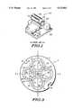
- FIG. 1is a perspective view of a conventional vibrator attached to a printed circuit board.
- FIG. 2is a block diagram of a selective call receiver in accordance with the present invention.
- FIG. 3is a top view of the armature structure according to the present invention.
- FIG. 4is a cross-sectional view of the message indicator according to the present invention.
- FIG. 5is a side view of the armature, member, and diaphragm in a vibratory motion.
- FIG. 6is a cross-sectional view of an alternate embodiment of the present invention.
- a selective call receivere.g. a pager, comprises an RF receiver 200 for receiving and demodulating a signal, a decoder 202 for decoding the signal, and a controller 204 for presenting an alert and message contained within the signal or an alert only via one of a plurality of output devices 206, 208.
- These output devicesinclude one or more of an audible alert 206, a tactile alert 206, and a visual alert 208.
- the alertmay be presented in response to selection of a user control 210, e.g. pushing a button or moving a slide switch. This basic function of a selective call receiver is well known to those skilled in the art.
- the controller 204may initiate an alert signal via the audible/tactile alert device 206, to provide either an audible alert or a tactile alert.
- the alert device 206responds to a first frequency to provide the audible alert, and to a second frequency to provide a sub-audible or tactile alert.
- the structure and operation of the audible/tactile alert device 206is hereinafter more fully described by reference to FIGS. 3, 4 and 5.
- an armature 2comprises a body 4 including curved, substantially planar springs 50, 52, 54, and 56 integrally positioned therein, an etched surface 42, and an opening 44.
- the armature 2may be manufactured by a single piece of metal that is chemically etched using known techniques to form the preferred embodiment.
- Each of the springs 50, 52, 54, and 56preferably comprise two members 6 and 8, 10 and 12, 14 and 16, and 18 and 20, respectively.
- the springs 50, 52, 54, and 56are formed by circular openings 22, 24, 26, and 28 and curved openings 30, 32, 34, and 36, respectively.
- openings 38 and 40are formed for mounting purposes although other variations could be utilized.
- the armature 2is made of international nickel alloy 902, with springs 50, 52, 54, and 56, chemically etched to a thickness of approximately 0.003 inches or less. This material is a constant modulus alloy so as to reduce temperature induced frequency changes and force impulse changes.
- the preferred design of the armature 2provides a linear spring rate due to the elastic bending of the members 6, 8, 10, 12, 14, 16, 18, and 20. Frequency tuning is preferably accomplished by adjusting the inside diameters of the springs 50, 52, 54, and 56 by a suitable etching, trimming, or grinding process.
- the ring geometrymakes it possible to elongate each of the members 6, 8, 10, 12, 14, 16, 18, and 20 by approximately 0.0015 inches without exceeding the required maximum fatigue stress level of 30,000 psi for the material selected in the preferred embodiment. It should be understood that the shapes and dimensions could change without varying from the intent of the invention.
- the audible/tactile alert device 206comprises the armature 2, positioned within a housing 402 and coupled all around the perimeter to the housing 402.
- a member 404comprises a top piece 406 and a bottom piece 408, which are preferably constructed of a non-magnetic metal. The top 406 and bottom 408 of the member 404 mate through the opening 44 in the armature 2 (see FIG. 3). The member 404 is thus attached to the armature 2 allowing movement of the member 404 about an equilibrium position.
- the bottom piece 408 of the member 404is also coupled to a magnet 410.
- the magnet 410is surrounded by a coil 412 forming an actuator for causing the members to move in response to an alternating current applied to the coil 412.
- the top piece 406 of the member 404is also coupled to a diaphragm 414 located within the housing 402.
- the diaphragm 414preferably comprises a substantially flat non-magnetic metal disk, preferably made out of beryllium.
- An aperture 416 in the housing 402 in combination with the moving diaphragm 414may be constructed via known techniques with such dimensions as to form a Helmholtz resonator cavity 418.
- an audible alertmay be emitted through the aperture 416 when the member 404 is vibrated at a first frequency.
- the audible alertin the preferred embodiment, comprises a signal having a frequency of approximately 3000 Hz.
- the member 404 and the armature 2are mechanically tuned to naturally also resonate at a second frequency of approximately 70 Hz.
- the armature 2is coupled to the housing 402 for transferring movement of the member 404 to the housing to generate a tactile alert. Since 70 Hz comprises generally sub-audible frequency, no audible sound will be heard. That is--the present invention provides a tactile alert by generation of a sub-audible signal.
- a maximum amplitude and impulseis provided at a relatively small power consumption. This is due to the restoring force created by tension in the springs 50, 52, 54, and 56 as each member 6, 8, 10, 12, 14, 16, 18, and 20 of the springs 50, 52, 54, and 56, extends approximately 0.0015 inches.
- the restoring forceis balanced by the perimeter of the armature 2, which is coupled to the housing 402.
- the driving force (unbalanced)is in the axis Z--Z and is typically 10% of the balanced restoring force, which is in the axis X--X and Y--Y. Therefore, the system uses approximately 10% of the stored energy to move the message indicator 206 (and thus the selective call receiver) each cycle, which increases the system's battery life.
- the indicator 206generates an impulse toward the user in one direction as compared to the prior art motor 100 which generates an impulse in all radial directions within the plane of rotational motion of the external unbalanced counterweight 106. Therefore, much of the force generated by the motor 100 is not felt in a tactile sense by the user. An equivalent tactile sensory response is obtained by the present invention while using less power and space than the conventional motor 100.
- the armature 2is in its stationary (equilibrium) position within message indicator 206 with a mass 500 comprised of the member 404, the magnet 410, and the diaphragm 414.
- the armature 2is held substantially rigid to the housing 402 along the perimeter.
- the indicator 206begins to vibrate, the armature 2 and mass 500 will move from its stationary position, along azis Z--Z, to its maximum amplitude as represented by armature 2' and mass 500'.
- the armature 2' and mass 500'will oscillate to the opposed extreme as represented by armature 2" and mass 500". These oscillations produce either the audible alert at the first frequency of approximately 3000 Hz or the tactile alert at the second frequency of approximately 70 Hz.
- an alternate embodiment of the inventioncomprises a piezo-electric mechanism 602 for vibrating the indicator 206.
- At least one piezo-ceramic ring 602is coupled to the armature 2.
- the piezo-ceramic ring 602is attached to the perimeter of the armature 2 using a high Q mechanical adhesive, such as Armstrong 702.
- the armature 2is coupled to a member 604 comprising a top piece 606 and a bottom piece 608, which are preferably constructed of a non-magnetic metal.
- the top 606 and bottom 608 of the member 604mate through the opening 44 in the armature 2 (see FIG. 3).
- the member 604is attached to the armature 2 for movement about an equilibrium position.
- the armature 2is positioned between the top 616 and bottom 618 of a housing 614 at four points 60, 62, 64, and 66 (see FIG. 3).
- This arrangement of the armature 2 and the housing 614allows the armature 2 to expand in size along the axis X--X and Y--Y, in response to a force applied outwardly around the perimeter of the armature 2.
- the armature 2returns to its original dimensions when the force is removed.
- the bottom piece 608 of the member 604is also coupled to a magnet 610.
- the magnet 610attracts a fixed metal shield 612, which maintains tension on the armature 2.
- an alternating voltageis applied to the piezo-ceramic ring 602 to cause the piezo-ceramic ring 602 to alternately expand in size and return to equilibrium.
- the induced movement in the armature 2is along the axis X--X and Y--Y (see FIG. 3).
- the resulting movement of the member 604is along the axis Z--Z.
- the magnetic force between the magnet 610 and the shield 612maintains tension on the armature 2 while the piezo-ceramic ring 602 expands and returns. Therefore, the piezo-electric mechanism 602 composes an actuator for causing the member 604 to move in response to an alternating voltage applied to the piezo-ceramic ring 602.
- An aperture 618 in the housing 614 in combination with the moving diaphragm 616may be constructed via known techniques with such dimensions as to form a Helmholtz resonator cavity 620.
- an audible alertmay be emitted through the aperture 618 when the member 604 is vibrated at a first frequency.
- the audible alertin this embodiment, comprises a signal having a frequency of approximately 3000 Hz.
- the member 604 and the armature 2, in this embodiment,are mechanically tuned to naturally also resonate at a second frequency of approximately 70 Hz.
- the armature 2is coupled to the housing 614 for transferring movement of the member 604 to the housing 614 to generate a tactile alert. Since 70 Hz comprises generally a sub-audible frequency, no audible sound will be heard. That is-the present invention provides a tactile alert by generation of a sub-audible signal.
Landscapes
- Engineering & Computer Science (AREA)
- Signal Processing (AREA)
- Physics & Mathematics (AREA)
- Acoustics & Sound (AREA)
- Mobile Radio Communication Systems (AREA)
Abstract
Description
This invention relates in general to the field of message indicators, and more specifically, to vibrators and audible alert generators for selective call receivers.
Selective call receivers, e.g. pagers, typically alert a user upon the occurrence of one of a number of possible events. The alert can be an audible or a tactile alert. The latter alert provides a silent alert signal to the user.
The current art requires two separate devices within the selective call receiver to perform the two alerts. Referring to FIG. 1, conventional designs require avibrator motor 100 comprising acylindrical housing 102 having a rotatingshaft 104 attached to an externalunbalanced counterweight 106 to provide the "silent" tactile alert. Thecylindrical body 102 is held in place on a printedcircuit board 108 bymotor bracket 110. Additionally, a separate transducer (or amplifier and speaker system) is required to provide the audible alert.
The required two devices add substantial size and cost to the receiver. Also, they increase the amount of time required to assemble and to service the product. Ultimately, the reliability of receivers is degraded by the inclusion of these two electro-mechanical devices.
Conventional message alert designs also impede miniaturization, which is a significant drawback to modern receiver design trends. It is important that the overall size be reduced without reducing the vibration level required for the "silent" tactile alert, since this would defeat the advantage of the size reduction.
Accordingly, there exists a need in the art for a single, high reliability device to provide both the audible and tactile alerts.
In carrying out one form of this invention, there is provided an apparatus for providing audible and tactile alerts comprising a housing, a flexible member within the housing and coupled thereto, and a moving member coupled to the flexible member for movement about an equilibrium position, the moving member including a permanent magnet. The apparatus also comprises actuator means coupled to the moving member for causing the moving member to move at a first frequency for generating an audible alert and at a second frequency for generating a sub-audible or tactile alert. The actuator means includes electromagnet means for causing the permanent magnet and the moving member to move, the movement at the second frequency being substantially transferred to the housing for generating the sub-audible or tactile alert.
FIG. 1 is a perspective view of a conventional vibrator attached to a printed circuit board.
FIG. 2 is a block diagram of a selective call receiver in accordance with the present invention.
FIG. 3 is a top view of the armature structure according to the present invention.
FIG. 4 is a cross-sectional view of the message indicator according to the present invention.
FIG. 5 is a side view of the armature, member, and diaphragm in a vibratory motion.
FIG. 6 is a cross-sectional view of an alternate embodiment of the present invention.
Referring to FIG. 2, a selective call receiver, e.g. a pager, comprises anRF receiver 200 for receiving and demodulating a signal, adecoder 202 for decoding the signal, and acontroller 204 for presenting an alert and message contained within the signal or an alert only via one of a plurality ofoutput devices audible alert 206, atactile alert 206, and avisual alert 208. Additionally, the alert may be presented in response to selection of auser control 210, e.g. pushing a button or moving a slide switch. This basic function of a selective call receiver is well known to those skilled in the art.
According to the invention, thecontroller 204 may initiate an alert signal via the audible/tactile alert device 206, to provide either an audible alert or a tactile alert. Thealert device 206 responds to a first frequency to provide the audible alert, and to a second frequency to provide a sub-audible or tactile alert. The structure and operation of the audible/tactile alert device 206 is hereinafter more fully described by reference to FIGS. 3, 4 and 5.
Referring to FIG. 3, anarmature 2 comprises abody 4 including curved, substantiallyplanar springs etched surface 42, and anopening 44. Thearmature 2 may be manufactured by a single piece of metal that is chemically etched using known techniques to form the preferred embodiment. Each of thesprings members springs circular openings curved openings openings
In the preferred embodiment, thearmature 2 is made of international nickel alloy 902, withsprings armature 2 provides a linear spring rate due to the elastic bending of themembers springs members
Referring to FIG. 4, the audible/tactile alert device 206 comprises thearmature 2, positioned within ahousing 402 and coupled all around the perimeter to thehousing 402. Amember 404 comprises atop piece 406 and abottom piece 408, which are preferably constructed of a non-magnetic metal. The top 406 andbottom 408 of themember 404 mate through the opening 44 in the armature 2 (see FIG. 3). Themember 404 is thus attached to thearmature 2 allowing movement of themember 404 about an equilibrium position.
Thebottom piece 408 of themember 404 is also coupled to amagnet 410. Themagnet 410 is surrounded by a coil 412 forming an actuator for causing the members to move in response to an alternating current applied to the coil 412.
Thetop piece 406 of themember 404 is also coupled to adiaphragm 414 located within thehousing 402. Thediaphragm 414 preferably comprises a substantially flat non-magnetic metal disk, preferably made out of beryllium. Anaperture 416 in thehousing 402 in combination with the movingdiaphragm 414 may be constructed via known techniques with such dimensions as to form a Helmholtzresonator cavity 418. According to the invention, an audible alert may be emitted through theaperture 416 when themember 404 is vibrated at a first frequency. The audible alert, in the preferred embodiment, comprises a signal having a frequency of approximately 3000 Hz.
Referring to FIGS. 3 and 4, themember 404 and thearmature 2, in the preferred embodiment, are mechanically tuned to naturally also resonate at a second frequency of approximately 70 Hz. As previously mentioned, thearmature 2 is coupled to thehousing 402 for transferring movement of themember 404 to the housing to generate a tactile alert. Since 70 Hz comprises generally sub-audible frequency, no audible sound will be heard. That is--the present invention provides a tactile alert by generation of a sub-audible signal.
At mechanical resonance, a maximum amplitude and impulse is provided at a relatively small power consumption. This is due to the restoring force created by tension in thesprings member springs armature 2, which is coupled to thehousing 402. The driving force (unbalanced) is in the axis Z--Z and is typically 10% of the balanced restoring force, which is in the axis X--X and Y--Y. Therefore, the system uses approximately 10% of the stored energy to move the message indicator 206 (and thus the selective call receiver) each cycle, which increases the system's battery life.
According to the invention, theindicator 206 generates an impulse toward the user in one direction as compared to theprior art motor 100 which generates an impulse in all radial directions within the plane of rotational motion of the externalunbalanced counterweight 106. Therefore, much of the force generated by themotor 100 is not felt in a tactile sense by the user. An equivalent tactile sensory response is obtained by the present invention while using less power and space than theconventional motor 100.
Referring to FIGS. 4 and 5, thearmature 2 is in its stationary (equilibrium) position withinmessage indicator 206 with amass 500 comprised of themember 404, themagnet 410, and thediaphragm 414. Thearmature 2 is held substantially rigid to thehousing 402 along the perimeter. As theindicator 206 begins to vibrate, thearmature 2 andmass 500 will move from its stationary position, along azis Z--Z, to its maximum amplitude as represented by armature 2' and mass 500'. Due to the spring force provided bysprings armature 2" andmass 500". These oscillations produce either the audible alert at the first frequency of approximately 3000 Hz or the tactile alert at the second frequency of approximately 70 Hz.
Referring to FIG. 6, an alternate embodiment of the invention comprises a piezo-electric mechanism 602 for vibrating theindicator 206. At least one piezo-ceramic ring 602 is coupled to thearmature 2. The piezo-ceramic ring 602 is attached to the perimeter of thearmature 2 using a high Q mechanical adhesive, such as Armstrong 702. Thearmature 2 is coupled to amember 604 comprising atop piece 606 and abottom piece 608, which are preferably constructed of a non-magnetic metal. The top 606 andbottom 608 of themember 604 mate through theopening 44 in the armature 2 (see FIG. 3). Thus, themember 604 is attached to thearmature 2 for movement about an equilibrium position.
As can be seen, thearmature 2 is positioned between the top 616 andbottom 618 of ahousing 614 at fourpoints armature 2 and thehousing 614 allows thearmature 2 to expand in size along the axis X--X and Y--Y, in response to a force applied outwardly around the perimeter of thearmature 2. Thearmature 2 returns to its original dimensions when the force is removed.
Thebottom piece 608 of themember 604 is also coupled to amagnet 610. Themagnet 610 attracts a fixedmetal shield 612, which maintains tension on thearmature 2.
According to the invention, an alternating voltage is applied to the piezo-ceramic ring 602 to cause the piezo-ceramic ring 602 to alternately expand in size and return to equilibrium. The induced movement in thearmature 2 is along the axis X--X and Y--Y (see FIG. 3). The resulting movement of themember 604 is along the axis Z--Z. The magnetic force between themagnet 610 and theshield 612 maintains tension on thearmature 2 while the piezo-ceramic ring 602 expands and returns. Therefore, the piezo-electric mechanism 602 composes an actuator for causing themember 604 to move in response to an alternating voltage applied to the piezo-ceramic ring 602.
Themember 604 and thearmature 2, in this embodiment, are mechanically tuned to naturally also resonate at a second frequency of approximately 70 Hz. Thearmature 2 is coupled to thehousing 614 for transferring movement of themember 604 to thehousing 614 to generate a tactile alert. Since 70 Hz comprises generally a sub-audible frequency, no audible sound will be heard. That is-the present invention provides a tactile alert by generation of a sub-audible signal.
At mechanical resonance, the energy required to move thearmature 2 andmember 604 is substantially reduced, thus increasing battery life.
Claims (18)
1. An apparatus comprising:
a housing;
a flexible member within the housing and coupled thereto;
a moving member coupled to the flexible member for movement about an equilibrium position, the moving member including a permanent magnet; and
actuator means coupled to the moving member for causing the moving member to move at a first frequency for generating an audible alert and at a second frequency for generating a sub-audible or tactile alert, the actuator means including electromagnet means for causing the permanent magnet and the moving member to move, the movement at the second frequency being substantially transferred to the housing for generating the sub-audible or tactile alert.
2. The apparatus according to claim 1 further comprising:
a diaphragm coupled to the moving member and located within the housing for generating the audible alert in response to movement of the moving member.
3. The apparatus according to claim 2 wherein the diaphragm is resonant at the first frequency for generating the audible alert.
4. The apparatus according to claim 1 wherein the housing defines a cavity therewithin with an aperture through the housing for emitting the audible alert.
5. The apparatus according to claim 1 further comprising:
receiver means for receiving a message; and
controller means coupled to the receiver means and to the actuator means for presenting the message and one of the audible alert or the sub-audible or tactile alert in response to the message being received.
6. A method for vibrating a moving member coupled to a flexible member, the flexible member located substantially within a housing and coupled thereto, the method comprising the steps of piezo-electrically flexing the flexible member, and thereby vibrating the moving member coupled thereto, at a first frequency for providing an audible alert and at a second frequency for providing a sub-audible or tactile alert, the vibration of the moving member at the second frequency being substantially transferred to the housing for providing the sub-audible or tactile alert.
7. The method according to claim 6 further comprising the step of selecting one of the first frequency or the second frequency for vibrating the moving member.
8. The method according to claim 6 further comprising the step of flexing the flexible member in substantially one direction for moving the moving member in substantially a second direction that is different than the first direction.
9. An apparatus comprising:
a housing;
a flexible member within the housing and coupled thereto;
a moving member coupled to the flexible member for movement about an equilibrium position; and
piezo-electric actuator means coupled to the flexible member for causing the flexible member to flex thereby causing the moving member to move, the flexible member flexing at a first frequency or a second frequency for causing the moving member to move at the respective first and second frequency to generate an audible alert and a sub-audible or tactile alert, respectively, the movement at the second frequency being transferred to the housing for generating the sub-audible or tactile alert.
10. The apparatus according to claim 9 further comprising:
a diaphragm coupled to the moving member and located within the housing for generating the audible alert in response to movement of the moving member.
11. The apparatus according to claim 10 wherein the diaphragm is resonant at the first frequency for generating the audible alert.
12. The apparatus according to claim 9 wherein the housing defines a cavity therewithin with an aperture through the housing for emitting the audible alert.
13. The apparatus according to claim 9 further comprising:
receiver means for receiving a message; and
controller means coupled to the receiver means and to the actuator means for presenting the message and one of the audible alert or the sub-audible or tactile alert in response to the message being received.
14. A selective call receiver comprising:
receiver means for receiving a message;
controller means coupled to the receiver means for presenting the message, the controller means also initiates an alert signal; and
alert means coupled to the controller means for presenting one of an audible alert or a sub-audible or tactile alert in response to the alert signal, the alert means further comprising:
a housing;
a flexible member within the housing and coupled thereto;
a moving member coupled to the flexible member for movement about an equilibrium position, the moving member including a permanent magnet;
a diaphragm coupled to the moving member and located within the housing for generating the audible alert in response to movement of the moving member; and
actuator means coupled to the moving member for causing the moving member to move at a first frequency for generating the audible alert and at a second frequency for generating the sub-audible or tactile alert, the actuator means including electromagnet means for causing the permanent magnet and the moving member to move, the movement at the second frequency being substantially transferred to the housing for generating the sub-audible or tactile alert.
15. The selective call receiver according to claim 14 wherein the controller means initiates the alert signal in response to receiving the message.
16. The selective call receiver according to claim 14 further comprising user control means coupled to the controller means for detecting user selection of the user control means, and wherein the controller means initiates the alert signal in response to user selection of the user control means.
17. The selective call receiver according to claim 14 wherein the diaphragm is resonant at the first frequency for generating the audible alert.
18. The selective call receiver according to claim 14 wherein the housing defines a cavity therewithin with an aperture through the housing for emitting the audible alert.
Priority Applications (1)
| Application Number | Priority Date | Filing Date | Title |
|---|---|---|---|
| US07/515,036US5172092A (en) | 1990-04-26 | 1990-04-26 | Selective call receiver having audible and tactile alerts |
Applications Claiming Priority (1)
| Application Number | Priority Date | Filing Date | Title |
|---|---|---|---|
| US07/515,036US5172092A (en) | 1990-04-26 | 1990-04-26 | Selective call receiver having audible and tactile alerts |
Publications (1)
| Publication Number | Publication Date |
|---|---|
| US5172092Atrue US5172092A (en) | 1992-12-15 |
Family
ID=24049732
Family Applications (1)
| Application Number | Title | Priority Date | Filing Date |
|---|---|---|---|
| US07/515,036Expired - LifetimeUS5172092A (en) | 1990-04-26 | 1990-04-26 | Selective call receiver having audible and tactile alerts |
Country Status (1)
| Country | Link |
|---|---|
| US (1) | US5172092A (en) |
Cited By (79)
| Publication number | Priority date | Publication date | Assignee | Title |
|---|---|---|---|---|
| US5293161A (en)* | 1990-06-18 | 1994-03-08 | Motorola, Inc. | Selective call receiver having a variable frequency vibrator |
| US5379032A (en)* | 1992-11-02 | 1995-01-03 | Motorola, Inc. | Impulse transducer enunciator |
| WO1995001622A1 (en)* | 1993-06-30 | 1995-01-12 | Motorola, Inc. | A magnetic vibrator |
| US5488351A (en)* | 1993-08-02 | 1996-01-30 | Motorola, Inc. | Rocking vibrator alert apparatus driven by opposite phases of a frequency generator |
| US5517574A (en)* | 1994-12-22 | 1996-05-14 | Motorola, Inc. | Dual function transducer housing |
| WO1996016487A1 (en)* | 1994-11-17 | 1996-05-30 | Motorola Inc. | Taut armature resonant impulse transducer |
| US5524061A (en)* | 1994-08-29 | 1996-06-04 | Motorola, Inc. | Dual mode transducer for a portable receiver |
| US5528697A (en)* | 1991-05-17 | 1996-06-18 | Namiki Precision Jewel Co., Ltd. | Integrated vibrating and sound producing device |
| US5602432A (en)* | 1993-08-11 | 1997-02-11 | Sayama Precision Industries Co., Ltd. | Silent warning vibration generator for portable equipment |
| US5619181A (en)* | 1994-11-21 | 1997-04-08 | Motorola, Inc. | Vibratory alerting device with audible sound generator |
| US5642413A (en)* | 1995-08-07 | 1997-06-24 | Little; Randall P. | Telephone call alert device with selectable alert modes |
| US5649020A (en)* | 1994-08-29 | 1997-07-15 | Motorola, Inc. | Electronic driver for an electromagnetic resonant transducer |
| US5650763A (en)* | 1996-06-03 | 1997-07-22 | Motorola, Inc. | Non-linear reciprocating device |
| US5696497A (en)* | 1992-01-22 | 1997-12-09 | Motorola, Inc. | Radio with silent and audible alerts |
| US5708726A (en)* | 1995-08-16 | 1998-01-13 | Motorola, Inc. | Taut armature resonant impulse transducer |
| US5767787A (en)* | 1992-02-05 | 1998-06-16 | Nec Corporation | Reduced size radio selective call receiver with a tactile alert capability by sub-audible sound |
| US5801466A (en)* | 1994-12-27 | 1998-09-01 | Uniden Corporation | Vibrator attaching structure |
| US5825297A (en)* | 1996-07-19 | 1998-10-20 | Motorola, Inc. | Taut armature reciprocating impulse transducer |
| US5861686A (en)* | 1997-08-05 | 1999-01-19 | Shinwood Audio Co. Ltd. | Device for generating waking vibrations or sounds |
| US5894263A (en)* | 1995-12-15 | 1999-04-13 | Matsushita Electric Industrial Co., Ltd. | Vibration generating apparatus |
| US5896096A (en)* | 1995-07-24 | 1999-04-20 | Samsung Electronics Co., Ltd. | Paging receiver and a sequential vibrating method therefor |
| US5898364A (en)* | 1996-08-09 | 1999-04-27 | Nec Corporation | Electronic equipment having vibration motor |
| US5903076A (en)* | 1996-02-20 | 1999-05-11 | A.C.E. Tech Co., Ltd. | Vibration actuator for pager |
| EP0845920A3 (en)* | 1996-11-29 | 1999-05-26 | Matsushita Electric Industrial Co., Ltd. | Electro-mechanical and acoustic transducer for portable terminal unit |
| JPH11191795A (en)* | 1997-12-25 | 1999-07-13 | Tokin Corp | Multi-functuional vibration actuator for telephone set, and telephone set mounting the actuator |
| US5936516A (en)* | 1997-01-31 | 1999-08-10 | Motorola, Inc. | Vibrating apparatus and method therefor |
| US5956622A (en)* | 1997-04-07 | 1999-09-21 | Shinwoo Audio Co., Ltd. | Device for generating calling vibrations or calling sounds in cellular or pager phones |
| US5961540A (en)* | 1997-09-05 | 1999-10-05 | Pacesetter, Inc. | Pancake annunciator |
| US6023515A (en)* | 1997-02-21 | 2000-02-08 | Motorola, Inc. | Mass excited acoustic device |
| WO2000013392A3 (en)* | 1998-08-31 | 2000-06-08 | Nasa | Piezoelectric vibrational and acoustic alert device |
| US6078126A (en)* | 1998-05-29 | 2000-06-20 | Motorola, Inc. | Resonant piezoelectric alerting device |
| US6097317A (en)* | 1996-05-03 | 2000-08-01 | J. C. Decaux International | Portable appliance for informing the users of a bus network about waiting times at stops in the network |
| US6118979A (en)* | 1996-11-22 | 2000-09-12 | Robert B. Nicholson, III | Method for signaling an incoming telephone call without an audible signal |
| EP1053794A1 (en)* | 1999-05-17 | 2000-11-22 | Tokin Corporation | Vibration actuator and mobile communication terminal |
| US6198206B1 (en) | 1998-03-20 | 2001-03-06 | Active Control Experts, Inc. | Inertial/audio unit and construction |
| US6211775B1 (en)* | 1998-06-15 | 2001-04-03 | Samsung Electro-Mechanics Co., Ltd. | Vibration apparatus capable of generating and externally transmitting a sound wave of audible frequency and transmitting a vibration for notification |
| US6281785B1 (en)* | 1997-03-21 | 2001-08-28 | Sanyo Electric Co., Ltd. | Vibration generator for notification and portable communication device using the vibration generator |
| WO2000001131A3 (en)* | 1998-06-26 | 2001-09-13 | Projects Unltd Inc | Piezoelectric vibrational and acoustic personal communication device |
| EP0906790A4 (en)* | 1996-06-21 | 2001-10-17 | Sanyo Electric Co | Vibration generator for reporting and portable communication equipment using the same |
| US6340936B1 (en)* | 2000-08-18 | 2002-01-22 | Mcgaffey John F. | Accessible pedestrian signal system |
| US6587091B2 (en) | 2001-04-23 | 2003-07-01 | Michael Lawrence Serpa | Stabilized tactile output mechanism for computer interface devices |
| US6684556B1 (en)* | 2000-06-07 | 2004-02-03 | David B. Arbuckle | Remotely controlled vibrating fishing bait |
| US6717305B2 (en)* | 2000-02-17 | 2004-04-06 | Koninklijke Philips Electronics N.V. | Apparatus having an electroacoustic transducer forming a sound reproducing means and a part of vibration generating means |
| EP1473050A1 (en)* | 1998-08-18 | 2004-11-03 | Medtronic MiniMed, Inc. | External infusion device with remote programming, bolus estimator and/or vibration alarm capabilities |
| US20050145472A1 (en)* | 2004-01-02 | 2005-07-07 | Beckwith Leslie A. | Vibrating pedestrian push button station |
| US20050154815A1 (en)* | 2004-01-14 | 2005-07-14 | International Business Machines Corporation | Seamless user interactions for portable storage devices |
| US20060066569A1 (en)* | 2003-12-08 | 2006-03-30 | Immersion Corporation, A Delaware Corporation | Methods and systems for providing haptic messaging to handheld communication devices |
| US20060117258A1 (en)* | 2004-11-30 | 2006-06-01 | Raymond Yu | User interface device |
| US20060128439A1 (en)* | 2004-12-13 | 2006-06-15 | Lg Electronics Inc. | Method for automatically switching incoming call signal output mode from vibration to ringtone using vibration detection unit in mobile communication terminal |
| US20060136631A1 (en)* | 2002-12-08 | 2006-06-22 | Immersion Corporation, A Delaware Corporation | Methods and systems for providing haptic messaging to handheld communication devices |
| US20060136630A1 (en)* | 2002-12-08 | 2006-06-22 | Immersion Corporation, A Delaware Corporation | Methods and systems for providing haptic messaging to handheld communication devices |
| US20060274035A1 (en)* | 2002-04-25 | 2006-12-07 | Immersion Corporation | Haptic feedback using rotary harmonic moving mass |
| US20060284849A1 (en)* | 2002-12-08 | 2006-12-21 | Grant Danny A | Methods and systems for providing a virtual touch haptic effect to handheld communication devices |
| US20070005835A1 (en)* | 2002-12-08 | 2007-01-04 | Immersion Corporation, A Delaware Corporation | Using haptic effects to enhance information content in communications |
| US7182691B1 (en) | 2000-09-28 | 2007-02-27 | Immersion Corporation | Directional inertial tactile feedback using rotating masses |
| US20070195059A1 (en)* | 1999-09-30 | 2007-08-23 | Immersion Corporation, A Delaware Corporation | Increasing force transmissibility for tactile feedback interface devices |
| US20080058038A1 (en)* | 2006-08-31 | 2008-03-06 | Motorola, Inc. | Portable electronic device having a hinge mechanism |
| US7369115B2 (en) | 2002-04-25 | 2008-05-06 | Immersion Corporation | Haptic devices having multiple operational modes including at least one resonant mode |
| US20080133648A1 (en)* | 2002-12-08 | 2008-06-05 | Immersion Corporation | Methods and Systems for Providing Haptic Messaging to Handheld Communication Devices |
| US7446752B2 (en) | 1999-09-28 | 2008-11-04 | Immersion Corporation | Controlling haptic sensations for vibrotactile feedback interface devices |
| US20090067662A1 (en)* | 2007-09-06 | 2009-03-12 | Sony Corporation | Speaker unit and audio output robot device |
| US7548232B2 (en) | 2000-01-19 | 2009-06-16 | Immersion Corporation | Haptic interface for laptop computers and other portable devices |
| US7561142B2 (en) | 1999-07-01 | 2009-07-14 | Immersion Corporation | Vibrotactile haptic feedback devices |
| US20100260371A1 (en)* | 2009-04-10 | 2010-10-14 | Immerz Inc. | Systems and methods for acousto-haptic speakers |
| US7944435B2 (en) | 1998-06-23 | 2011-05-17 | Immersion Corporation | Haptic feedback for touchpads and other touch controls |
| US8031059B2 (en) | 2002-05-31 | 2011-10-04 | Motorola Mobility, Inc. | Communication system |
| US20110244926A1 (en)* | 2008-12-19 | 2011-10-06 | Celsius X Vi Ii | Mobile telephone |
| US8059088B2 (en) | 2002-12-08 | 2011-11-15 | Immersion Corporation | Methods and systems for providing haptic messaging to handheld communication devices |
| US8169402B2 (en) | 1999-07-01 | 2012-05-01 | Immersion Corporation | Vibrotactile haptic feedback devices |
| US8232969B2 (en) | 2004-10-08 | 2012-07-31 | Immersion Corporation | Haptic feedback for button and scrolling action simulation in touch input devices |
| US8441444B2 (en) | 2000-09-28 | 2013-05-14 | Immersion Corporation | System and method for providing directional tactile sensations |
| US8665115B2 (en) | 2010-06-22 | 2014-03-04 | Novax Industries Corporation | Accessible pedestrian signal system |
| RU2513031C1 (en)* | 2012-11-09 | 2014-04-20 | Общество с ограниченной ответственностью "Константин Чайкин" | Device for calling mobile telephone with natural sounds of mechanical musical instrument and/or mechanical animation of animation figures (versions) and mobile telephone called with natural sounds of mechanical musical instrument and/or mechanical animation of animation figures (versions) |
| US20140167890A1 (en)* | 2012-12-19 | 2014-06-19 | C&K Components S.A.S. | Electrical switch arrangement and device for controlling an apparatus comprising such an arrangement |
| RU2538090C1 (en)* | 2013-11-15 | 2015-01-10 | Общество с ограниченной ответственностью "Константин Чайкин" | Ringing apparatus on mobile telephone using natural sounds of mechanical musical instrument and mobile telephone with ringing using natural sounds of mechanical musical instrument |
| RU2539197C1 (en)* | 2013-11-15 | 2015-01-20 | Общество с ограниченной ответственностью "Константин Чайкин" | Mobile telephone ringing device by mechanical animation of animation figures and mobile telephone having ringing by mechanical animation of animation figures |
| US9019087B2 (en) | 2007-10-16 | 2015-04-28 | Immersion Corporation | Synchronization of haptic effect data in a media stream |
| US20180085786A1 (en)* | 2016-09-23 | 2018-03-29 | Apple Inc. | Multi-core, multi-dimension electromagnet |
| US9949390B1 (en)* | 2016-12-22 | 2018-04-17 | Apple Inc. | Electronic device including movable magnet based actuator for deforming a display and related methods |
Citations (8)
| Publication number | Priority date | Publication date | Assignee | Title |
|---|---|---|---|---|
| US4378551A (en)* | 1980-12-05 | 1983-03-29 | Motorola, Inc. | Radio signal receiving apparatus with a security circuitry |
| US4385295A (en)* | 1981-09-29 | 1983-05-24 | Motorola, Inc. | Pager with visible display indicating unread messages |
| US4731603A (en)* | 1985-08-30 | 1988-03-15 | Unisys Corporation | Tactile alarm system for gaining the attention of an individual |
| US4786889A (en)* | 1985-12-10 | 1988-11-22 | Nec Corporation | Battery casing for a paging receiver |
| US4823110A (en)* | 1988-04-22 | 1989-04-18 | Magna International Inc. | Tone generator with improved diaphragm mounting |
| US4851836A (en)* | 1986-04-29 | 1989-07-25 | Amalgamated Wireless Limited | Audio-tactile pedestrian push button signalling system |
| US4918438A (en)* | 1986-05-30 | 1990-04-17 | Nec Corporation | Paging receiver having audible and vibrator annunciating means |
| US4931765A (en)* | 1989-02-09 | 1990-06-05 | Motorola, Inc. | Unitized housing for silent and tone pager alerting system |
- 1990
- 1990-04-26USUS07/515,036patent/US5172092A/ennot_activeExpired - Lifetime
Patent Citations (8)
| Publication number | Priority date | Publication date | Assignee | Title |
|---|---|---|---|---|
| US4378551A (en)* | 1980-12-05 | 1983-03-29 | Motorola, Inc. | Radio signal receiving apparatus with a security circuitry |
| US4385295A (en)* | 1981-09-29 | 1983-05-24 | Motorola, Inc. | Pager with visible display indicating unread messages |
| US4731603A (en)* | 1985-08-30 | 1988-03-15 | Unisys Corporation | Tactile alarm system for gaining the attention of an individual |
| US4786889A (en)* | 1985-12-10 | 1988-11-22 | Nec Corporation | Battery casing for a paging receiver |
| US4851836A (en)* | 1986-04-29 | 1989-07-25 | Amalgamated Wireless Limited | Audio-tactile pedestrian push button signalling system |
| US4918438A (en)* | 1986-05-30 | 1990-04-17 | Nec Corporation | Paging receiver having audible and vibrator annunciating means |
| US4823110A (en)* | 1988-04-22 | 1989-04-18 | Magna International Inc. | Tone generator with improved diaphragm mounting |
| US4931765A (en)* | 1989-02-09 | 1990-06-05 | Motorola, Inc. | Unitized housing for silent and tone pager alerting system |
Non-Patent Citations (6)
| Title |
|---|
| Motorola Service Manual 68P81006B85 C Bravo Series, Numeric Display Pagers, A05JRB/C Models, 929 932 MHz , 1989, p. 15.* |
| Motorola Service Manual 68P81006B85-C "`Bravo` Series, Numeric Display Pagers, A05JRB/C Models, 929-932 MHz", © 1989, p. 15. |
| Motorola Service Manual 68P81046C35 A, Bravo Series, Binary GSC Radio Pagers, Tone and Silent Alert, 406 420 MHz, 450 512 MHz , 1988, p. 11.* |
| Motorola Service Manual 68P81046C35-A, "`Bravo` Series, Binary GSC Radio Pagers, Tone and Silent Alert, 406-420 MHz, 450-512 MHz", © 1988, p. 11. |
| Motorola Service Manual 68P81047C75 A, Bravo Series, Numeric Display Pagers, 138 174 MHz , 1986, p. 15.* |
| Motorola Service Manual 68P81047C75-A, "`Bravo` Series, Numeric Display Pagers, 138-174 MHz", © 1986, p. 15. |
Cited By (128)
| Publication number | Priority date | Publication date | Assignee | Title |
|---|---|---|---|---|
| US5293161A (en)* | 1990-06-18 | 1994-03-08 | Motorola, Inc. | Selective call receiver having a variable frequency vibrator |
| US5528697A (en)* | 1991-05-17 | 1996-06-18 | Namiki Precision Jewel Co., Ltd. | Integrated vibrating and sound producing device |
| US5696497A (en)* | 1992-01-22 | 1997-12-09 | Motorola, Inc. | Radio with silent and audible alerts |
| US6252516B1 (en)* | 1992-01-22 | 2001-06-26 | Motorola, Inc. | Radio with silent and audible alerts |
| US6252515B1 (en) | 1992-01-22 | 2001-06-26 | Motorola, Inc. | Radio with silent and audible alerts |
| US5767787A (en)* | 1992-02-05 | 1998-06-16 | Nec Corporation | Reduced size radio selective call receiver with a tactile alert capability by sub-audible sound |
| US5379032A (en)* | 1992-11-02 | 1995-01-03 | Motorola, Inc. | Impulse transducer enunciator |
| WO1995001622A1 (en)* | 1993-06-30 | 1995-01-12 | Motorola, Inc. | A magnetic vibrator |
| US5488351A (en)* | 1993-08-02 | 1996-01-30 | Motorola, Inc. | Rocking vibrator alert apparatus driven by opposite phases of a frequency generator |
| US5602432A (en)* | 1993-08-11 | 1997-02-11 | Sayama Precision Industries Co., Ltd. | Silent warning vibration generator for portable equipment |
| US5649020A (en)* | 1994-08-29 | 1997-07-15 | Motorola, Inc. | Electronic driver for an electromagnetic resonant transducer |
| US5524061A (en)* | 1994-08-29 | 1996-06-04 | Motorola, Inc. | Dual mode transducer for a portable receiver |
| WO1996016487A1 (en)* | 1994-11-17 | 1996-05-30 | Motorola Inc. | Taut armature resonant impulse transducer |
| CN1089970C (en)* | 1994-11-17 | 2002-08-28 | 摩托罗拉公司 | Taut armature resonant impulse transducer |
| US5546069A (en)* | 1994-11-17 | 1996-08-13 | Motorola, Inc. | Taut armature resonant impulse transducer |
| US5619181A (en)* | 1994-11-21 | 1997-04-08 | Motorola, Inc. | Vibratory alerting device with audible sound generator |
| US5517574A (en)* | 1994-12-22 | 1996-05-14 | Motorola, Inc. | Dual function transducer housing |
| US5801466A (en)* | 1994-12-27 | 1998-09-01 | Uniden Corporation | Vibrator attaching structure |
| US5896096A (en)* | 1995-07-24 | 1999-04-20 | Samsung Electronics Co., Ltd. | Paging receiver and a sequential vibrating method therefor |
| US5642413A (en)* | 1995-08-07 | 1997-06-24 | Little; Randall P. | Telephone call alert device with selectable alert modes |
| US5708726A (en)* | 1995-08-16 | 1998-01-13 | Motorola, Inc. | Taut armature resonant impulse transducer |
| US5894263A (en)* | 1995-12-15 | 1999-04-13 | Matsushita Electric Industrial Co., Ltd. | Vibration generating apparatus |
| SG79927A1 (en)* | 1995-12-15 | 2001-04-17 | Matsushita Electric Industrial Co Ltd | Vibration generating apparatus |
| EP0791405A3 (en)* | 1996-02-20 | 2000-01-19 | A.C.E. Tech Co., Ltd. | Vibration actuator for pager |
| US5903076A (en)* | 1996-02-20 | 1999-05-11 | A.C.E. Tech Co., Ltd. | Vibration actuator for pager |
| US6097317A (en)* | 1996-05-03 | 2000-08-01 | J. C. Decaux International | Portable appliance for informing the users of a bus network about waiting times at stops in the network |
| WO1997047092A1 (en)* | 1996-06-03 | 1997-12-11 | Motorola Inc. | Non-linear reciprocating device |
| US5650763A (en)* | 1996-06-03 | 1997-07-22 | Motorola, Inc. | Non-linear reciprocating device |
| US6404085B2 (en) | 1996-06-21 | 2002-06-11 | Sanyo Electric Co., Ltd | Vibration generator for reporting and portable communication equipment using the same |
| EP0906790A4 (en)* | 1996-06-21 | 2001-10-17 | Sanyo Electric Co | Vibration generator for reporting and portable communication equipment using the same |
| US5825297A (en)* | 1996-07-19 | 1998-10-20 | Motorola, Inc. | Taut armature reciprocating impulse transducer |
| US5898364A (en)* | 1996-08-09 | 1999-04-27 | Nec Corporation | Electronic equipment having vibration motor |
| US6118979A (en)* | 1996-11-22 | 2000-09-12 | Robert B. Nicholson, III | Method for signaling an incoming telephone call without an audible signal |
| US6208237B1 (en) | 1996-11-29 | 2001-03-27 | Matsushita Electric Industrial Co. Ltd. | Electro-mechanical and acoustic transducer for portable terminal unit |
| EP0845920A3 (en)* | 1996-11-29 | 1999-05-26 | Matsushita Electric Industrial Co., Ltd. | Electro-mechanical and acoustic transducer for portable terminal unit |
| US5936516A (en)* | 1997-01-31 | 1999-08-10 | Motorola, Inc. | Vibrating apparatus and method therefor |
| US6023515A (en)* | 1997-02-21 | 2000-02-08 | Motorola, Inc. | Mass excited acoustic device |
| US6281785B1 (en)* | 1997-03-21 | 2001-08-28 | Sanyo Electric Co., Ltd. | Vibration generator for notification and portable communication device using the vibration generator |
| US5956622A (en)* | 1997-04-07 | 1999-09-21 | Shinwoo Audio Co., Ltd. | Device for generating calling vibrations or calling sounds in cellular or pager phones |
| US5861686A (en)* | 1997-08-05 | 1999-01-19 | Shinwood Audio Co. Ltd. | Device for generating waking vibrations or sounds |
| US5961540A (en)* | 1997-09-05 | 1999-10-05 | Pacesetter, Inc. | Pancake annunciator |
| JPH11191795A (en)* | 1997-12-25 | 1999-07-13 | Tokin Corp | Multi-functuional vibration actuator for telephone set, and telephone set mounting the actuator |
| US6376967B2 (en) | 1998-03-20 | 2002-04-23 | Active Control Experts, Inc. | Inertial/audio unit and construction |
| US6359371B1 (en) | 1998-03-20 | 2002-03-19 | Active Control Experts, Inc. | Inertial/audio unit and construction |
| US6563254B2 (en) | 1998-03-20 | 2003-05-13 | Cymer, Inc. | Inertial/audio unit and construction |
| US6198206B1 (en) | 1998-03-20 | 2001-03-06 | Active Control Experts, Inc. | Inertial/audio unit and construction |
| US6078126A (en)* | 1998-05-29 | 2000-06-20 | Motorola, Inc. | Resonant piezoelectric alerting device |
| US6211775B1 (en)* | 1998-06-15 | 2001-04-03 | Samsung Electro-Mechanics Co., Ltd. | Vibration apparatus capable of generating and externally transmitting a sound wave of audible frequency and transmitting a vibration for notification |
| US8031181B2 (en) | 1998-06-23 | 2011-10-04 | Immersion Corporation | Haptic feedback for touchpads and other touch controls |
| US7944435B2 (en) | 1998-06-23 | 2011-05-17 | Immersion Corporation | Haptic feedback for touchpads and other touch controls |
| US7978183B2 (en) | 1998-06-23 | 2011-07-12 | Immersion Corporation | Haptic feedback for touchpads and other touch controls |
| US7982720B2 (en) | 1998-06-23 | 2011-07-19 | Immersion Corporation | Haptic feedback for touchpads and other touch controls |
| US8059105B2 (en) | 1998-06-23 | 2011-11-15 | Immersion Corporation | Haptic feedback for touchpads and other touch controls |
| US8049734B2 (en) | 1998-06-23 | 2011-11-01 | Immersion Corporation | Haptic feedback for touchpads and other touch control |
| US8063893B2 (en) | 1998-06-23 | 2011-11-22 | Immersion Corporation | Haptic feedback for touchpads and other touch controls |
| WO2000001131A3 (en)* | 1998-06-26 | 2001-09-13 | Projects Unltd Inc | Piezoelectric vibrational and acoustic personal communication device |
| EP2266645A2 (en)* | 1998-08-18 | 2010-12-29 | Medtronic MiniMed, Inc. | External infusion device with remote programming, bolus estimator and/or vibration alarm capabilities |
| EP1473050A1 (en)* | 1998-08-18 | 2004-11-03 | Medtronic MiniMed, Inc. | External infusion device with remote programming, bolus estimator and/or vibration alarm capabilities |
| US6259188B1 (en) | 1998-08-31 | 2001-07-10 | Projects Unlimited, Inc. | Piezoelectric vibrational and acoustic alert for a personal communication device |
| WO2000013392A3 (en)* | 1998-08-31 | 2000-06-08 | Nasa | Piezoelectric vibrational and acoustic alert device |
| EP1053794A1 (en)* | 1999-05-17 | 2000-11-22 | Tokin Corporation | Vibration actuator and mobile communication terminal |
| US6600938B1 (en) | 1999-05-17 | 2003-07-29 | Nec Tokin Corporation | Vibration actuator and mobile communication terminal |
| US8169402B2 (en) | 1999-07-01 | 2012-05-01 | Immersion Corporation | Vibrotactile haptic feedback devices |
| US7561142B2 (en) | 1999-07-01 | 2009-07-14 | Immersion Corporation | Vibrotactile haptic feedback devices |
| US9492847B2 (en) | 1999-09-28 | 2016-11-15 | Immersion Corporation | Controlling haptic sensations for vibrotactile feedback interface devices |
| US7446752B2 (en) | 1999-09-28 | 2008-11-04 | Immersion Corporation | Controlling haptic sensations for vibrotactile feedback interface devices |
| US9411420B2 (en) | 1999-09-30 | 2016-08-09 | Immersion Corporation | Increasing force transmissibility for tactile feedback interface devices |
| US20070195059A1 (en)* | 1999-09-30 | 2007-08-23 | Immersion Corporation, A Delaware Corporation | Increasing force transmissibility for tactile feedback interface devices |
| US9280205B2 (en) | 1999-12-17 | 2016-03-08 | Immersion Corporation | Haptic feedback for touchpads and other touch controls |
| US8059104B2 (en) | 2000-01-19 | 2011-11-15 | Immersion Corporation | Haptic interface for touch screen embodiments |
| US7548232B2 (en) | 2000-01-19 | 2009-06-16 | Immersion Corporation | Haptic interface for laptop computers and other portable devices |
| US8188981B2 (en) | 2000-01-19 | 2012-05-29 | Immersion Corporation | Haptic interface for touch screen embodiments |
| US8063892B2 (en) | 2000-01-19 | 2011-11-22 | Immersion Corporation | Haptic interface for touch screen embodiments |
| US6717305B2 (en)* | 2000-02-17 | 2004-04-06 | Koninklijke Philips Electronics N.V. | Apparatus having an electroacoustic transducer forming a sound reproducing means and a part of vibration generating means |
| US6684556B1 (en)* | 2000-06-07 | 2004-02-03 | David B. Arbuckle | Remotely controlled vibrating fishing bait |
| US6340936B1 (en)* | 2000-08-18 | 2002-01-22 | Mcgaffey John F. | Accessible pedestrian signal system |
| US8441444B2 (en) | 2000-09-28 | 2013-05-14 | Immersion Corporation | System and method for providing directional tactile sensations |
| US7182691B1 (en) | 2000-09-28 | 2007-02-27 | Immersion Corporation | Directional inertial tactile feedback using rotating masses |
| US6587091B2 (en) | 2001-04-23 | 2003-07-01 | Michael Lawrence Serpa | Stabilized tactile output mechanism for computer interface devices |
| US7369115B2 (en) | 2002-04-25 | 2008-05-06 | Immersion Corporation | Haptic devices having multiple operational modes including at least one resonant mode |
| US8576174B2 (en) | 2002-04-25 | 2013-11-05 | Immersion Corporation | Haptic devices having multiple operational modes including at least one resonant mode |
| JP2010191959A (en)* | 2002-04-25 | 2010-09-02 | Immersion Corp | Haptic feedback using rotary harmonic moving mass |
| US7952559B2 (en) | 2002-04-25 | 2011-05-31 | Immersion Corporation | Haptic feedback using rotary harmonic moving mass |
| US20060274035A1 (en)* | 2002-04-25 | 2006-12-07 | Immersion Corporation | Haptic feedback using rotary harmonic moving mass |
| US7161580B2 (en) | 2002-04-25 | 2007-01-09 | Immersion Corporation | Haptic feedback using rotary harmonic moving mass |
| US8031059B2 (en) | 2002-05-31 | 2011-10-04 | Motorola Mobility, Inc. | Communication system |
| US20060136630A1 (en)* | 2002-12-08 | 2006-06-22 | Immersion Corporation, A Delaware Corporation | Methods and systems for providing haptic messaging to handheld communication devices |
| US20060284849A1 (en)* | 2002-12-08 | 2006-12-21 | Grant Danny A | Methods and systems for providing a virtual touch haptic effect to handheld communication devices |
| US20060136631A1 (en)* | 2002-12-08 | 2006-06-22 | Immersion Corporation, A Delaware Corporation | Methods and systems for providing haptic messaging to handheld communication devices |
| US8830161B2 (en) | 2002-12-08 | 2014-09-09 | Immersion Corporation | Methods and systems for providing a virtual touch haptic effect to handheld communication devices |
| US20080133648A1 (en)* | 2002-12-08 | 2008-06-05 | Immersion Corporation | Methods and Systems for Providing Haptic Messaging to Handheld Communication Devices |
| US7779166B2 (en) | 2002-12-08 | 2010-08-17 | Immersion Corporation | Using haptic effects to enhance information content in communications |
| US8803795B2 (en) | 2002-12-08 | 2014-08-12 | Immersion Corporation | Haptic communication devices |
| US8059088B2 (en) | 2002-12-08 | 2011-11-15 | Immersion Corporation | Methods and systems for providing haptic messaging to handheld communication devices |
| US8316166B2 (en) | 2002-12-08 | 2012-11-20 | Immersion Corporation | Haptic messaging in handheld communication devices |
| US20070005835A1 (en)* | 2002-12-08 | 2007-01-04 | Immersion Corporation, A Delaware Corporation | Using haptic effects to enhance information content in communications |
| US20060066569A1 (en)* | 2003-12-08 | 2006-03-30 | Immersion Corporation, A Delaware Corporation | Methods and systems for providing haptic messaging to handheld communication devices |
| US6982630B2 (en)* | 2004-01-02 | 2006-01-03 | Polara Engineering, Inc. | Vibrating pedestrian push button station |
| US20050145472A1 (en)* | 2004-01-02 | 2005-07-07 | Beckwith Leslie A. | Vibrating pedestrian push button station |
| US20050154815A1 (en)* | 2004-01-14 | 2005-07-14 | International Business Machines Corporation | Seamless user interactions for portable storage devices |
| US7234014B2 (en)* | 2004-01-14 | 2007-06-19 | International Business Machines Corporation | Seamless user interactions for portable storage devices |
| US8232969B2 (en) | 2004-10-08 | 2012-07-31 | Immersion Corporation | Haptic feedback for button and scrolling action simulation in touch input devices |
| US8264465B2 (en) | 2004-10-08 | 2012-09-11 | Immersion Corporation | Haptic feedback for button and scrolling action simulation in touch input devices |
| US7456821B2 (en) | 2004-11-30 | 2008-11-25 | Immersion Corporation | User interface device |
| US20060117258A1 (en)* | 2004-11-30 | 2006-06-01 | Raymond Yu | User interface device |
| US7912509B2 (en)* | 2004-12-13 | 2011-03-22 | Lg Electronics Inc. | Method for automatically switching incoming call signal output mode from vibration to ringtone using vibration detection unit in mobile communication terminal |
| US20060128439A1 (en)* | 2004-12-13 | 2006-06-15 | Lg Electronics Inc. | Method for automatically switching incoming call signal output mode from vibration to ringtone using vibration detection unit in mobile communication terminal |
| US20080058038A1 (en)* | 2006-08-31 | 2008-03-06 | Motorola, Inc. | Portable electronic device having a hinge mechanism |
| US8199957B2 (en)* | 2007-09-06 | 2012-06-12 | Sony Corporation | Speaker unit and audio output robot device |
| US20090067662A1 (en)* | 2007-09-06 | 2009-03-12 | Sony Corporation | Speaker unit and audio output robot device |
| CN101384095B (en)* | 2007-09-06 | 2012-12-26 | 索尼株式会社 | Speaker unit and audio output robot device |
| US9019087B2 (en) | 2007-10-16 | 2015-04-28 | Immersion Corporation | Synchronization of haptic effect data in a media stream |
| US10088903B2 (en) | 2007-10-16 | 2018-10-02 | Immersion Corporation | Synchronization of haptic effect data in a media stream |
| US8423091B2 (en)* | 2008-12-19 | 2013-04-16 | Celsius X Vi Ii | Mobile telephone |
| CN102257796A (en)* | 2008-12-19 | 2011-11-23 | 摄氏十六二公司 | mobile phone |
| CN102257796B (en)* | 2008-12-19 | 2014-03-05 | 摄氏十六二公司 | mobile phone |
| US20110244926A1 (en)* | 2008-12-19 | 2011-10-06 | Celsius X Vi Ii | Mobile telephone |
| US20100260371A1 (en)* | 2009-04-10 | 2010-10-14 | Immerz Inc. | Systems and methods for acousto-haptic speakers |
| US9185492B2 (en)* | 2009-04-10 | 2015-11-10 | Immerz, Inc. | Systems and methods for acousto-haptic speakers |
| US8665115B2 (en) | 2010-06-22 | 2014-03-04 | Novax Industries Corporation | Accessible pedestrian signal system |
| RU2513031C1 (en)* | 2012-11-09 | 2014-04-20 | Общество с ограниченной ответственностью "Константин Чайкин" | Device for calling mobile telephone with natural sounds of mechanical musical instrument and/or mechanical animation of animation figures (versions) and mobile telephone called with natural sounds of mechanical musical instrument and/or mechanical animation of animation figures (versions) |
| US9058946B2 (en)* | 2012-12-19 | 2015-06-16 | C&K Components S.A.S. | Electrical switch arrangement and device for controlling an apparatus comprising such an arrangement |
| US20140167890A1 (en)* | 2012-12-19 | 2014-06-19 | C&K Components S.A.S. | Electrical switch arrangement and device for controlling an apparatus comprising such an arrangement |
| RU2539197C1 (en)* | 2013-11-15 | 2015-01-20 | Общество с ограниченной ответственностью "Константин Чайкин" | Mobile telephone ringing device by mechanical animation of animation figures and mobile telephone having ringing by mechanical animation of animation figures |
| RU2538090C1 (en)* | 2013-11-15 | 2015-01-10 | Общество с ограниченной ответственностью "Константин Чайкин" | Ringing apparatus on mobile telephone using natural sounds of mechanical musical instrument and mobile telephone with ringing using natural sounds of mechanical musical instrument |
| US20180085786A1 (en)* | 2016-09-23 | 2018-03-29 | Apple Inc. | Multi-core, multi-dimension electromagnet |
| US10744531B2 (en)* | 2016-09-23 | 2020-08-18 | Apple Inc. | Multi-core, multi-dimension electromagnet |
| US9949390B1 (en)* | 2016-12-22 | 2018-04-17 | Apple Inc. | Electronic device including movable magnet based actuator for deforming a display and related methods |
Similar Documents
| Publication | Publication Date | Title |
|---|---|---|
| US5172092A (en) | Selective call receiver having audible and tactile alerts | |
| US5023504A (en) | Piezo-electric resonant vibrator for selective call receiver | |
| US5107540A (en) | Electromagnetic resonant vibrator | |
| JP2850158B2 (en) | Stabilized electromagnetic resonance armature haptic vibrator | |
| US5624155A (en) | Electromagnetic transducer | |
| US6404085B2 (en) | Vibration generator for reporting and portable communication equipment using the same | |
| KR100245379B1 (en) | Vibration generating apparatus | |
| JP3366507B2 (en) | Vibration generator | |
| JPH10500064A (en) | Thoth armature resonant shockwave converter | |
| US4147899A (en) | Broadband electromagnetic sound source with differently tuned diaphragms | |
| WO1990008421A1 (en) | Vibrator | |
| JPH09205763A (en) | Vibration generator | |
| JPH10258253A (en) | Vibration generating method and vibration generating device | |
| US4233679A (en) | Adjustable piezoelectric transducer for a watch | |
| JPH09172763A (en) | Vibration generator | |
| WO1992019018A1 (en) | Piezo-electric resonant vibrator for a selective call receiver | |
| JP3576524B2 (en) | Vibration generator and portable device using the same | |
| KR950004957B1 (en) | Electromagnetic resonator vibrator | |
| JP2000166210A (en) | Sounding oscillating body | |
| JP2958146B2 (en) | Piezoelectric alarm | |
| US3172100A (en) | Ringer clapper assembly | |
| JPH04207697A (en) | Piezoelectric alarming device | |
| JPH0519681A (en) | Piezoelectric annunciation device | |
| JP2002238093A (en) | Electro-mechanical acoustic converter | |
| JPH11207041A (en) | Toy |
Legal Events
| Date | Code | Title | Description |
|---|---|---|---|
| AS | Assignment | Owner name:MOTOROLA, INC., ILLINOIS Free format text:ASSIGNMENT OF ASSIGNORS INTEREST.;ASSIGNORS:ROLLINS, THOMAS J.;HOLDEN, HAROLD;MOONEY, CHARLES W.;REEL/FRAME:005288/0664;SIGNING DATES FROM 19900420 TO 19900423 Owner name:MOTOROLA, INC., ILLINOIS Free format text:ASSIGNMENT OF ASSIGNORS INTEREST.;ASSIGNOR:NGUYEN, TUAN K.;REEL/FRAME:005288/0659 Effective date:19900420 | |
| STCF | Information on status: patent grant | Free format text:PATENTED CASE | |
| FPAY | Fee payment | Year of fee payment:4 | |
| FPAY | Fee payment | Year of fee payment:8 | |
| FPAY | Fee payment | Year of fee payment:12 |