US5172005A - Engineered lighting system for tdi inspection comprising means for controlling lighting elements in accordance with specimen displacement - Google Patents
Engineered lighting system for tdi inspection comprising means for controlling lighting elements in accordance with specimen displacementDownload PDFInfo
- Publication number
- US5172005A US5172005AUS07/658,093US65809391AUS5172005AUS 5172005 AUS5172005 AUS 5172005AUS 65809391 AUS65809391 AUS 65809391AUS 5172005 AUS5172005 AUS 5172005A
- Authority
- US
- United States
- Prior art keywords
- array
- light emitting
- emitting diodes
- light
- video inspection
- Prior art date
- Legal status (The legal status is an assumption and is not a legal conclusion. Google has not performed a legal analysis and makes no representation as to the accuracy of the status listed.)
- Expired - Lifetime
Links
Images


Classifications
- G—PHYSICS
- G01—MEASURING; TESTING
- G01N—INVESTIGATING OR ANALYSING MATERIALS BY DETERMINING THEIR CHEMICAL OR PHYSICAL PROPERTIES
- G01N21/00—Investigating or analysing materials by the use of optical means, i.e. using sub-millimetre waves, infrared, visible or ultraviolet light
- G01N21/84—Systems specially adapted for particular applications
- G01N21/88—Investigating the presence of flaws or contamination
- G01N21/89—Investigating the presence of flaws or contamination in moving material, e.g. running paper or textiles
- G01N21/8901—Optical details; Scanning details
- G01N21/8903—Optical details; Scanning details using a multiple detector array
- G—PHYSICS
- G01—MEASURING; TESTING
- G01N—INVESTIGATING OR ANALYSING MATERIALS BY DETERMINING THEIR CHEMICAL OR PHYSICAL PROPERTIES
- G01N21/00—Investigating or analysing materials by the use of optical means, i.e. using sub-millimetre waves, infrared, visible or ultraviolet light
- G01N21/84—Systems specially adapted for particular applications
- G01N21/88—Investigating the presence of flaws or contamination
- G01N21/89—Investigating the presence of flaws or contamination in moving material, e.g. running paper or textiles
- G01N21/8901—Optical details; Scanning details
- H—ELECTRICITY
- H04—ELECTRIC COMMUNICATION TECHNIQUE
- H04N—PICTORIAL COMMUNICATION, e.g. TELEVISION
- H04N7/00—Television systems
- H04N7/18—Closed-circuit television [CCTV] systems, i.e. systems in which the video signal is not broadcast
- H04N7/181—Closed-circuit television [CCTV] systems, i.e. systems in which the video signal is not broadcast for receiving images from a plurality of remote sources
- H—ELECTRICITY
- H04—ELECTRIC COMMUNICATION TECHNIQUE
- H04N—PICTORIAL COMMUNICATION, e.g. TELEVISION
- H04N7/00—Television systems
- H04N7/18—Closed-circuit television [CCTV] systems, i.e. systems in which the video signal is not broadcast
- H04N7/188—Capturing isolated or intermittent images triggered by the occurrence of a predetermined event, e.g. an object reaching a predetermined position
- G—PHYSICS
- G01—MEASURING; TESTING
- G01N—INVESTIGATING OR ANALYSING MATERIALS BY DETERMINING THEIR CHEMICAL OR PHYSICAL PROPERTIES
- G01N21/00—Investigating or analysing materials by the use of optical means, i.e. using sub-millimetre waves, infrared, visible or ultraviolet light
- G01N21/84—Systems specially adapted for particular applications
- G01N21/88—Investigating the presence of flaws or contamination
- G01N21/8806—Specially adapted optical and illumination features
- G01N2021/8835—Adjustable illumination, e.g. software adjustable screen
- G—PHYSICS
- G01—MEASURING; TESTING
- G01N—INVESTIGATING OR ANALYSING MATERIALS BY DETERMINING THEIR CHEMICAL OR PHYSICAL PROPERTIES
- G01N21/00—Investigating or analysing materials by the use of optical means, i.e. using sub-millimetre waves, infrared, visible or ultraviolet light
- G01N21/84—Systems specially adapted for particular applications
- G01N21/88—Investigating the presence of flaws or contamination
- G01N21/8806—Specially adapted optical and illumination features
- G01N2021/8845—Multiple wavelengths of illumination or detection
- G—PHYSICS
- G01—MEASURING; TESTING
- G01N—INVESTIGATING OR ANALYSING MATERIALS BY DETERMINING THEIR CHEMICAL OR PHYSICAL PROPERTIES
- G01N21/00—Investigating or analysing materials by the use of optical means, i.e. using sub-millimetre waves, infrared, visible or ultraviolet light
- G01N21/84—Systems specially adapted for particular applications
- G01N21/88—Investigating the presence of flaws or contamination
- G01N21/8851—Scan or image signal processing specially adapted therefor, e.g. for scan signal adjustment, for detecting different kinds of defects, for compensating for structures, markings, edges
- G01N2021/8887—Scan or image signal processing specially adapted therefor, e.g. for scan signal adjustment, for detecting different kinds of defects, for compensating for structures, markings, edges based on image processing techniques
- G—PHYSICS
- G01—MEASURING; TESTING
- G01N—INVESTIGATING OR ANALYSING MATERIALS BY DETERMINING THEIR CHEMICAL OR PHYSICAL PROPERTIES
- G01N2201/00—Features of devices classified in G01N21/00
- G01N2201/06—Illumination; Optics
- G01N2201/062—LED's
- G01N2201/0621—Supply
Definitions
- This applicationpertains to the art of machine vision and more particularly to high speed automated video inspection.
- the inventionis particularly applicable to automated video inspection of continuous web-like materials such as cloth, paper, MYLAR, sheet metal, etc., and will be described with particular reference thereto, although it will be appreciated that the invention has broader applications such as in the inspection of any continuously moving specimen whether discrete or continuous in which the specimen passes through the field of view of an associated inspection camera and in systems utilizing relatively low illumination levels.
- Machine vision systemshave obtained an established presence in industry to accomplish high speed video inspections. Such machine vision systems are generally comprised of a lighting system to illuminate a specimen and a camera for sensing light reflected therefrom. A digitized image is formed from an image received by the camera. Data representative of this image is then utilized for determining acceptability of the specimen in view of preselected physical characteristics thereof.
- Substantial productis manufactured as a continuous stream of webbed or sheet-like material. While the aforementioned systems are adequate for a number of inspections, they provide no means for acquiring a consistently detailed inspection image of a continuous stream of fast moving web material. Earlier attempts to achieve automated inspection of such materials relied upon line scan cameras with continuous illumination. Stroboscopic systems were also utilized but required intense illumination periods. It was therefore desirable that a system be provided which allows for detailed high speed video inspection on a continuous stream of web material or which utilizes heretofore inadequate lighting intensities with improved image integrity and which exhibits robustness over a wide range of specimens.
- TDItime delay integration
- TDI inspection techniquescenter on numeric processing, rather than lighting technique. Previous techniques are conducive to some "smearing" of each linear cross-section image. Also, often times different grades of webbing or even entirely different webbing materials may at various times be inspected by the same system. Similarly, non-webbing systems often encounter markedly different specimens at different times. Differences in reflectivity in these situations require compensation. This is typically accomplished by compensation in the inspection algorithm software. Even this is limited given that absolute light sensitivity limits are inherent in CCDs, and once a sensitivity threshold has been exceeded, information is lost and compensation is not possible.
- the present inventioncontemplates a new and improved TDI video inspection and engineered lighting system which overcomes all the above-referred problems, and others, and provides a video inspection system allowing for continuous inspection of a stream of web materials or other specimens with improved integrity.
- an engineered lighting video inspection systemincludes an array of light emitting elements.
- the light emitting elements of the arrayare secured such that they are controllable in one or more discrete subsets.
- a signal representative of a linear velocity of an associated specimen relative to the arrayis provided to a controller.
- the controllerfunctions to selectively enable the light emitting element for a short time period.
- Light of the array of light emitting elementsis, after exposure to the specimen, communicated to a light sensitive transducer array, the rows of which are synchronized to a continuous webbing material or other specimen.
- backlightingis provided by a plurality of lighting elements disposed on a side of the specimen opposite of the light sensitive transducer.
- An advantage of the present inventionis the provision of a video inspection system for accomplishing detailed inspection of a continuous stream of sheet or web-like materials or other specimens.
- Another advantage of the present inventionis the provision of a system which allows for obtaining a frozen image of sequential areas of the web material.
- Yet another advantage of the present inventionis the provision of a system which allows for accumulation of multiple image data sets from selected areas of a continuous stream of web materials to accomplish improved high speed, detailed video inspection thereof with relatively low light levels, in a system adaptable to a wide range of webbing materials.
- Yet another advantageis the provision of an inspection system which achieves an improved signal-to-noise ratio for captured images.
- Yet another advantageis the provision of an inspection system employing lighting having improved characteristics, consistency, stability and reliability.
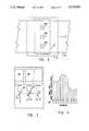
- FIG. 1illustrates a video inspection system employing an array of light emitting diodes
- FIG. 2illustrates an overhead view of three cameras positioned to accomplish image acquisition for inspection of webbing material
- FIG. 3illustrates an optional dual-camera inspection embodiment
- FIG. 4is a graph of shift time versus position for an inspection of a continuous moving stream of webbing material
- FIG. 5illustrates the illumination and CCD subsystems employed in the system of FIG. 1;
- FIG. 6illustrates a flow chart of operation of the subject TDI engineered lighting inspection operation
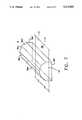
- FIG. 7is an alternate embodiment of the primary lighting array illustrated in FIGS. 1 and 5.
- FIG. 1illustrates an engineered video inspection system A which includes an engineered illumination system or means B, a data acquisition system or means C, and a computer system or means D.
- the illumination system Bis formed from an array of a plurality of light emitting elements 10 preferably comprised of solid-state lighting elements, such as a plurality of light emitting diodes ("LEDs").
- LEDslight emitting diodes
- Light emitting diodesadvantageously provide a fast responsive, long lived, and consistent light output.
- the light emitting diodesare focused to a generally narrow beam or cone of light emanating therefrom, which cone has a generally selected angle.
- a similar effect to a focused LEDsmay realized by employing a wider beam coupled with a decreased distance between the LEDs and a specimen.
- Typical, focused, light emitting diodesinclude a bullet-shaped casing which functions as a lens to project the narrow beam or cone of light therefrom. What focus is used, the arrangement of the devices, and the angles of illumination chosen is extremely application dependent. Conventionally available focused light emitting diodes have a beam of light generally wide angle (20° at the vertex), or 10° from a perpendicular centerline thereof. The subject system employs selection of LED angles which are highly application dependent. The more focused LEDs allow for concentration of a maximum amount of light from a given LED in a small area while concurrently maintaining uniformity in illumination. This also provides for a higher intensity of illumination on a specified area, subjecting the area to individual controllability of intensities and angles thereacross to controllability of individual or groups or subsets of light emitting diodes.
- Light emitting diodesmay be pulsed at extremely high currents provided that the duration is sufficiently small to prevent heat build-up which may damage the PN junction forming the diode. It is found that a duration in the range of 1 to 200 microseconds allows for provisions of such high currents with no or nominal damage to the LED. As will be described further below, it will be seen that this duration is also sufficient to "freeze" the image of a rapidly moving specimen so that a still image may be captured therefrom.
- 240 scan linesare implemented in the CCD array. Accordingly, 240 pulses and 240 exposures are integrated for each linear cross section of a specimen.
- the subject systemconcurrently flashes all or some of the diodes 10 in a duration of approximately 4 ⁇ sec given the light accumulation properties of TDI.
- operation in the range of 0.1 ⁇ sec to 100 ⁇ secreturns most advantages associated with the subject system.
- Each LEDis suitably supplied with between 1 mA and 500 Ma of current during this duration. A value of 73 Ma has proven acceptable. Suitable power supplies to accomplish such pulsing are well within the understanding of one of ordinary skill in the art and will not be described herein.
- the 4 ⁇ sec timeis selected to advantageously provide low duty cycle compared to the typical horizontal scan time for NTSC video signals.
- a 15.75 Khz scan rateprovides a 63 ⁇ sec horizontal scan time. Accordingly, the 4 ⁇ sec pulse provides a 4/63 duty cycle. This particular rate with actual duty cycle is proportioned to a scan rate implemented for a particular application.
- the light emitting diodes 10are secured by a bracket or securing means 12 in a generally hemi-cylindrical array 16.
- Such an array structureadvantageously provides generally uniform illumination to a rectangular light field 14.
- This structureis suitably fabricated from a flexible printed circuit board portion secured to two hemispherical printed circuit board end portions. LEDs are mounted on the interior portion of the array 16, and are preferably placed as closely as possible to one another to maximize illumination and minimize transitions therebetween, thereby forming a more uniform light field.
- this particular structureis employed in the preferred embodiment, it will be appreciated that various other array structures may be employed for illumination of various specimens.
- Angled lightingi.e., lighting which communicated from one or more LEDS to a specimen and is reflected off the specimen surface to a camera with a stated angle at less than 180°, is advantageously employed for improved detection of certain surface defects.
- Such systemsmay optionally implement a perspective correcting lens to maintain image characteristics through the progression within the CCD array.
- a perspective correcting lensallows for direction of light from an array to a specimen at a non-perpendicular angle while negating artifacts which would otherwise result from such an orientation. For example, angled (nonperpendicular) light from a rectangular array which illuminates a specimen causes a trapezoidal illumination area.
- the video receptor of the resultant imageis similarly distorted. The reflected image of the lens itself can thus be eliminated by use of a perspective correcting lens when highly reflective materials are being inspected thus allowing the desired degree of homogeneity in the imaged web.
- the light emitting diodes 10are also suitably subdivided into a plurality of groups or subsets 20. Light emitting diodes of each of the subsets 20 are controlled together via connections 22 with a power supply and junction box 24. Grouping of the light emitting elements provides a means with which control of the intensity along selected subsections of an associated specimen may be made or by which selected angles of illumination may be provided. Such structure also provides an ability to compensate for degrading or burned-out elements by boosting output of surrounding elements. It further provides for reduction of reflected light reaching any given region of the camera sensor.
- a portion of the light emitting elements 10is formed into a backlight array 26.
- Backlightingis often advantageously employed for inspection of light transmissive specimens or subportions of specimens.
- the backlight array 26is secured so as to be generally planar. Such a planar orientation is generally best suited for backlighting applications, although it will be appreciated that various other orientations may be successfully utilized.
- light emitting diodes of the backlight array 26are suitably formed into a plurality of subsets 28, interconnected with power supply and junction box 24. These connections have been omitted from FIG. 1 for ease in illustration. Such formation of subsets provides for controllability analogous to that provided with the arrangement above-described for primary array portion 16.
- FIG. 1Illustrated in FIG. 1 is a cross-sectional side view of a diffuser 30.
- the diffuser 30is advantageously formed as a hemi-cylindrical shape to be similar to the shape of the array 16, and placed internally thereof.
- the optional diffuserfunctions to smooth transitions between LEDs of the array, thereby providing an even more uniform light field.
- segment 38 of a stream of webbing materialwhich is in generally continuous motion in the direction so indicated.
- webbing materialwill be understood to refer to any sheetlike material, such as paper, cloth, sheet metal, plastic, laminates, and the like. It is understood that the system is also advantageously employed in discrete specimen systems. However, for simplicity descriptions herein will generally be with sole reference to webbing environments.
- a conveyor driver(not shown) continuously moves the web 38 through the light field 14 at a generally high speed. Web position is measured by a web position/velocity sensor, such as a tachometer 40. Light from light emitting diodes 10 of the primary array portion 16 is reflected from the web 38.
- Reflected light from a viewing area 42is received through a lens 44 of a camera 46. Although only one camera is illustrated in the cross-sectional view of the figure, it will be shown below that often a plurality of cameras are advantageously employed.
- the viewing area 42is isolated as much as possible from ambient light, i.e., light not provided by light from the primary (or secondary) lighting array(s) 16 (28).
- the lens 44 of camera 46is secured to extend slightly into the light field 14 through an aperture portion 52.
- the lens 44is preferably formed as a "pinhole" unit to minimize image artifacts due to the camera itself. Such lens arrangements are typically less than 3/8" in diameter.
- the aperture portionis suitably disposed at a generally central portion of the array should one camera be utilized, and at equivalent intervals in embodiments employing a plurality of cameras.
- the subject systemin its preferred embodiment, employs a TDI camera, VISIONEER 4050 manufactured by Picker International, Inc.
- the camera 46includes a CCD array in the preferred embodiment. It will be appreciated that CCD arrays are usually M ⁇ N rectangular arrays of photosensitive transducer elements, wherein M and N are positive, non-zero integers, usually multiples of two.
- the camera of the preferred embodimentfunctions as 244 rows of CCD elements, each row having 610 pixels.
- the camera 46is oriented relative to the web 40 such that each row is generally perpendicular to the direction of travel thereof.
- Typical CCD arraysare sensitive to a selected number of gray scale levels, for black and white systems, or primary colors, for color systems.
- CCD camerasallow for individual addressing of rows of transducer element thereof, analogously to the raster scan associated with conventional cathode ray tubes ("CRTs").
- CCD elementsalso operate as integrators which provide an electrical signal representative of an intensity of light exposed thereto over time.
- a CCD transducer elementalso has the ability to store light intensity data. This property is useful for achieving a still image of a specimen or portion thereof by strobing or pulsing a light source when the moving specimen is otherwise in a generally darkened field of view.
- the camera 46also advantageously includes an adjustment system 48 for control of focus, planetary, vertical, horizontal properties. Orthogonality must be maintained between sensor and inspected material. Such adjustment may be done manually, or in conjunction with signals provided by the digital computer system D by data communication camera sync and control lines.
- Image data acquired from camera 46is communicated, through video signal line 60, to the digital computer system D, and more particularly to the computer 62 thereof.
- the computer 62includes a central processor (CPU), memory, an I/O unit, and a suitable software and junction box 24 and with the webbing speed sensor 40.
- the computer 62determine acceptability of the specimens by a comparison of digitized image data with data representative of acceptability.
- FIG. 2illustrates an embodiment in which three cameras, 46a, 46b, and 46c are oriented relative to webbing material 38 in a mutual linear relationship. Respective viewing areas of the cameras are linearly aligned to provided a cross-section of the entire specimen surface. Securing the cameras in this manner provides an extended viewing area 42 sufficient to encompass a cross-section of a relatively wide webbing.
- FIG. 3illustrates an embodiment in which camera 46 is itself formed from a plurality of cameras.
- light from a specimenis communicated to a partially silvered mirror 70.
- a portionpasses directly to lens 44' of camera 46'.
- a second light portionis reflected from mirror 72 to lens 44" of camera 46".
- Implementation of a dual or multiple camera structure, such as that illustrated by FIG. 3,advantageously provides a means by which selected portions of the specimen may be provided with either increased resolution to accomplish specialized inspections or optical filtering thereon. For example, a seam or scoring in the inspected web material might be subject to heightened scrutiny by virtue of utilization of a secondary camera element focused specifically thereon.
- a third camerais also advantageously implemented for additional subportion analysis, as illustrated in phantom as numeral 72' in FIG. 3. Lighting to of such multiple camera beam-splitter environments will generally not yield as desirable a result or design because of the intense lighting required to provide enough light to each camera (when the exposure time is short and) since the splitting reduces the intensity inherently.
- FIGS. 4 and 5a graph illustrating operation of the charge coupled devices within the camera or cameras 46 is provided.
- positionis represented by the abscissa while shift time is represented by the ordinate.
- shift timeis represented by the ordinate.
- a series of illuminations or light pulsesare represented by the rectangles 80 of the graph.
- rows or scan lines of eachare preferably synchronized between all cameras. It is also equivalent to provide multiple pulses per scan line if advantageous.
- Synchronization between the CCD and the webbingmay be accomplished by control of web velocity or of CCD row increments.
- the CCD row incrementingis altered in accordance with variations in web speed by variations in shift control as described below.
- orientation of a CCD array 82is provided.
- the digital computer system Dwhich is illustrated with a keyboard, CRT, and mass storage media, and which includes the computer 62, receives a signal representative of web velocity from a sensor 40. This information is in turn utilized to sequence the scan of row 86 of a CCD array elements 88, via row scan selected circuitry illustrated as shift register 90. Similar sequencing is provided for each CCD array in multiple camera embodiments. The webbing progression is continuously monitored and the shift time implemented by the row select circuitry 90 is altered in accordance therewith. The graph of FIG. 4 illustrates the variation and shift time in accordance with the web speed.
- step 102data representative of web speed is obtained from tachometer 40.
- step 104web speed data is utilized to synchronize the shift register or registers of the CCD cameras with the web speed velocity data obtained in step 102.
- step 106the array or arrays of LEDs is pulsed for a short duration, approximately 4 ⁇ sec. in the preferred embodiment as noted above. This duration, by virtue of the synchronization with the webbing speed, is timed at the point when the previous shifting operation has settled, thereby providing the minimized smearing. Lighting intensity is also alterable in connection with this step.
- the digital computerinstructs shifting of shift register 90 to cause progression of rows of the CCD array 82 towards register 92. Accordingly, at this time the contents of previous row 86N are then communicated to register 92 in step 110. This data is, in turn, communicated through image processor 94 to digital computer system D at step 112. At this stage, a suitable algorithm is performed on the data to determine acceptability of the specimen.
- Step 114lighting intensity adjustment data is received to allow for selective control of intensity in step 106.
- Step 116allows completed inspections to terminate at step 118 and continuing inspections to progress back to step 102.
- FIG. 7illustrates an alternative embodiment of the primary array 16 illustrated in FIGS. 1 and 5.
- the primary array 16'is formed from a series of planar rectangular portions 16a'-16d' and first and second planar end portions 16e' and 16f'.
- an interior portion of the array 16'contains closely packed LEDs directed to the webbing material 38'.
- This embodimentadvantageously allows for fabrication of the array 16' from common, planar printed circuit board material. This orientation nonetheless provides for substantial uniform illumination over a light field 14' which encompasses a portion of the webbing 38'. It will be appreciated that more or fewer rectangular subsections may be utilized depending on the degree to which a hemispherical array is more closely advantageously approximated.
- array formatsmay also be utilized, which formats are dictated by properties or dimensions of the webbing material and the angles and intensities of illumination required to provide the desired qualities of the illumination. For example, hemispherical, "tiffany-lamp” style, etc. or otherwise may be utilized.
- the modulated row select CCD structureprovides a system with which multiple readings of a single linear subsection of a continuously moving web material may be achieved without the necessity of using a plurality of cameras or a moving camera. Data achieved by multiple acquisition provides more reliable data upon which inspection may be made. Also lighting specific to subsections of the CCD may be advantageously applied at appropriate angles and intensities.
Landscapes
- Engineering & Computer Science (AREA)
- Immunology (AREA)
- Physics & Mathematics (AREA)
- Health & Medical Sciences (AREA)
- Life Sciences & Earth Sciences (AREA)
- Chemical & Material Sciences (AREA)
- Analytical Chemistry (AREA)
- Biochemistry (AREA)
- General Health & Medical Sciences (AREA)
- Textile Engineering (AREA)
- General Physics & Mathematics (AREA)
- Signal Processing (AREA)
- Multimedia (AREA)
- Pathology (AREA)
- Investigating Materials By The Use Of Optical Means Adapted For Particular Applications (AREA)
- Circuit Arrangement For Electric Light Sources In General (AREA)
- Length Measuring Devices By Optical Means (AREA)
- Endoscopes (AREA)
- Preparation Of Compounds By Using Micro-Organisms (AREA)
- Testing, Inspecting, Measuring Of Stereoscopic Televisions And Televisions (AREA)
- Time-Division Multiplex Systems (AREA)
Abstract
Description
Claims (27)
Priority Applications (12)
| Application Number | Priority Date | Filing Date | Title |
|---|---|---|---|
| US07/658,093US5172005A (en) | 1991-02-20 | 1991-02-20 | Engineered lighting system for tdi inspection comprising means for controlling lighting elements in accordance with specimen displacement |
| EP92905181AEP0572479B1 (en) | 1991-02-20 | 1992-01-02 | Engineered lighting system for tdi inspection |
| AT92905181TATE161098T1 (en) | 1991-02-20 | 1992-01-02 | BUILT-IN LIGHTING DEVICE FOR TESTING WITH RUNTIME INTEGRATION |
| DE69223505TDE69223505T2 (en) | 1991-02-20 | 1992-01-02 | BUILT-IN LIGHTING DEVICE FOR TEST WITH RUNTIME INTEGRATION |
| ES92905181TES2050092T1 (en) | 1991-02-20 | 1992-01-02 | TECHNICAL LIGHTING SYSTEM FOR INSPECTION BY INTEGRATION IN TIME DELAYS. |
| CA002103864ACA2103864C (en) | 1991-02-20 | 1992-01-02 | Engineered lighting system for tdi inspection |
| PCT/US1992/000108WO1992015010A1 (en) | 1991-02-20 | 1992-01-02 | Engineered lighting system for tdi inspection |
| FI933665AFI933665A7 (en) | 1991-02-20 | 1992-01-02 | Technical awareness system for TDI inspection |
| JP4505300AJP2540707B2 (en) | 1991-02-20 | 1992-01-02 | Improved TDI inspection lighting system |
| DE0572479TDE572479T1 (en) | 1991-02-20 | 1992-01-02 | BUILT-IN LIGHTING DEVICE FOR TEST WITH RUNTIME INTEGRATION. |
| AU12740/92AAU1274092A (en) | 1991-02-20 | 1992-01-02 | Engineered lighting system for tdi inspection |
| US07/990,009US5365084A (en) | 1991-02-20 | 1992-12-14 | Video inspection system employing multiple spectrum LED illumination |
Applications Claiming Priority (1)
| Application Number | Priority Date | Filing Date | Title |
|---|---|---|---|
| US07/658,093US5172005A (en) | 1991-02-20 | 1991-02-20 | Engineered lighting system for tdi inspection comprising means for controlling lighting elements in accordance with specimen displacement |
Related Child Applications (1)
| Application Number | Title | Priority Date | Filing Date |
|---|---|---|---|
| US07/990,009Continuation-In-PartUS5365084A (en) | 1991-02-20 | 1992-12-14 | Video inspection system employing multiple spectrum LED illumination |
Publications (1)
| Publication Number | Publication Date |
|---|---|
| US5172005Atrue US5172005A (en) | 1992-12-15 |
Family
ID=24639872
Family Applications (1)
| Application Number | Title | Priority Date | Filing Date |
|---|---|---|---|
| US07/658,093Expired - LifetimeUS5172005A (en) | 1991-02-20 | 1991-02-20 | Engineered lighting system for tdi inspection comprising means for controlling lighting elements in accordance with specimen displacement |
Country Status (10)
| Country | Link |
|---|---|
| US (1) | US5172005A (en) |
| EP (1) | EP0572479B1 (en) |
| JP (1) | JP2540707B2 (en) |
| AT (1) | ATE161098T1 (en) |
| AU (1) | AU1274092A (en) |
| CA (1) | CA2103864C (en) |
| DE (2) | DE69223505T2 (en) |
| ES (1) | ES2050092T1 (en) |
| FI (1) | FI933665A7 (en) |
| WO (1) | WO1992015010A1 (en) |
Cited By (76)
| Publication number | Priority date | Publication date | Assignee | Title |
|---|---|---|---|---|
| WO1994014053A1 (en)* | 1992-12-14 | 1994-06-23 | Pressco Technology, Inc. | Video inspection system employing multiple spectrum led illumination |
| DE29504073U1 (en)* | 1995-03-10 | 1995-05-04 | Fa. Hermann Heye, 31683 Obernkirchen | Device for testing for light reflecting defects |
| US5461417A (en)* | 1993-02-16 | 1995-10-24 | Northeast Robotics, Inc. | Continuous diffuse illumination method and apparatus |
| WO1996041299A1 (en)* | 1995-06-07 | 1996-12-19 | Pressco Technology, Inc. | Inspection system for exterior article surfaces |
| US5600435A (en)* | 1995-05-24 | 1997-02-04 | Fori Automation, Inc. | Intelligent sensor method and apparatus for an optical wheel alignment machine |
| US5644140A (en)* | 1994-04-20 | 1997-07-01 | Siemens Aktiengesellschaft | Apparatus for checking semiconductor wafers with complementary light sources and two cameras |
| US5713661A (en)* | 1995-10-23 | 1998-02-03 | Northeast Robotics, Inc. | Hockey puck shaped continuous diffuse illumination apparatus and method |
| US5745176A (en)* | 1995-10-12 | 1998-04-28 | Ppt Vision, Inc. | Machine-vision illumination system and method for delineating a lighted volume from an unlighted volume |
| US5761540A (en)* | 1994-10-31 | 1998-06-02 | Northeast Robotics, Inc. | Illumination device with microlouver for illuminating an object with continuous diffuse light |
| US5764874A (en)* | 1994-10-31 | 1998-06-09 | Northeast Robotics, Inc. | Imaging system utilizing both diffuse and specular reflection characteristics |
| US5805279A (en)* | 1996-01-11 | 1998-09-08 | Alltrista Corporation | Method and apparatus for illuminating and imaging a can end coated with sealing material |
| US5842060A (en)* | 1994-10-31 | 1998-11-24 | Northeast Robotics Llc | Illumination device with curved beam splitter for illumination an object with continuous diffuse light |
| US5859924A (en)* | 1996-07-12 | 1999-01-12 | Robotic Vision Systems, Inc. | Method and system for measuring object features |
| WO1999020048A1 (en)* | 1997-10-10 | 1999-04-22 | Northeast Robotics Llc | Imaging method and system with elongate inspection zone |
| US5920643A (en)* | 1997-05-16 | 1999-07-06 | Northeast Robotics Llc | Flexible lighting element circuit and method of manufacturing the same |
| US5953130A (en)* | 1997-01-06 | 1999-09-14 | Cognex Corporation | Machine vision methods and apparatus for machine vision illumination of an object |
| US5978077A (en)* | 1996-10-31 | 1999-11-02 | Fori Automation, Inc. | Non-contact method and apparatus for determining camber and caster of a vehicle wheel |
| WO2000014517A1 (en)* | 1998-09-03 | 2000-03-16 | Semiconductor Technologies & Instruments, Inc. | Adaptive lighting system and method for machine vision apparatus |
| US6075883A (en)* | 1996-11-12 | 2000-06-13 | Robotic Vision Systems, Inc. | Method and system for imaging an object or pattern |
| US6170973B1 (en) | 1997-11-26 | 2001-01-09 | Cognex Corporation | Method and apparatus for wide-angle illumination in line-scanning machine vision devices |
| WO2001016585A1 (en)* | 1999-08-31 | 2001-03-08 | Cognex Corporation | Method and apparatus for providing uniform diffuse illumination to a surface |
| US6273338B1 (en) | 1998-09-22 | 2001-08-14 | Timothy White | Low cost color-programmable focusing ring light |
| US20020005892A1 (en)* | 2000-06-28 | 2002-01-17 | Erwin Herre | Illuminating unit for an article-sensing camera |
| US20020015152A1 (en)* | 2000-07-26 | 2002-02-07 | Biazzi Pier Silvano | Method and instrument for determining the distortion angles in textile fabrics or similar, whether fixed or in movement |
| US6384421B1 (en) | 1999-10-07 | 2002-05-07 | Logical Systems Incorporated | Vision system for industrial parts |
| US20020166983A1 (en)* | 2001-05-11 | 2002-11-14 | Orbotech Ltd | Optical inspection system employing a staring array scanner |
| US6488390B1 (en) | 1998-03-19 | 2002-12-03 | Ppt Vision, Inc. | Color-adjusted camera light and method |
| WO2003001189A1 (en)* | 2001-06-22 | 2003-01-03 | Orbotech Ltd. | High-sensitivity optical scanning using memory integration |
| US6526369B1 (en) | 1998-07-14 | 2003-02-25 | Voith Sulzer Papiertechnik Patent Gmbh | Apparatus and process for a cross-direction profile of a material web |
| US6624597B2 (en)* | 1997-08-26 | 2003-09-23 | Color Kinetics, Inc. | Systems and methods for providing illumination in machine vision systems |
| US20030222219A1 (en)* | 2000-12-22 | 2003-12-04 | Metso Automation Oy | Method and apparatus for controlling moisture profile of moving paper web |
| US20040114035A1 (en)* | 1998-03-24 | 2004-06-17 | Timothy White | Focusing panel illumination method and apparatus |
| US20040150714A1 (en)* | 2003-01-30 | 2004-08-05 | Test Research, Inc. | Optical-enhanced apparatus and method for illuminating printed circuit boards for inspection |
| US6788411B1 (en) | 1999-07-08 | 2004-09-07 | Ppt Vision, Inc. | Method and apparatus for adjusting illumination angle |
| US20040263834A1 (en)* | 1990-11-16 | 2004-12-30 | Applied Materials, Inc. | Optical inspection apparatus for substrate defect detection |
| EP1494012A1 (en)* | 2003-06-30 | 2005-01-05 | Emhart Glass S.A. | Container inspection machine with man-machine interface for identifying and defining back lights |
| US20050036138A1 (en)* | 1997-08-01 | 2005-02-17 | Guoheng Zhao | System for detecting anomalies and / or features of a surface |
| US20060144266A1 (en)* | 2003-02-10 | 2006-07-06 | Brown Stephen C | Sensing device |
| US20060262971A1 (en)* | 2005-05-18 | 2006-11-23 | Scott Foes | Transient defect detection algorithm |
| US20070153277A1 (en)* | 2005-12-29 | 2007-07-05 | Honeywell International Inc. | Color sensor |
| US20070258085A1 (en)* | 2006-05-02 | 2007-11-08 | Robbins Michael D | Substrate illumination and inspection system |
| US20080024794A1 (en)* | 2004-06-04 | 2008-01-31 | Yoko Miyazaki | Semiconductor Surface Inspection Apparatus and Method of Illumination |
| US20080030731A1 (en)* | 2006-05-02 | 2008-02-07 | Accretech Usa, Inc. | Automatic wafer edge inspection and review system |
| US20080128336A1 (en)* | 2002-08-12 | 2008-06-05 | Farook Afsari | Method of and apparatus for high speed, high quality, contaminant removal and color sorting of glass cullet |
| US20080137325A1 (en)* | 2006-09-29 | 2008-06-12 | Pastore Timothy M | Methods for providing diffuse light |
| US20080137323A1 (en)* | 2006-09-29 | 2008-06-12 | Pastore Timothy M | Methods for camera-based inspections |
| US20080137324A1 (en)* | 2006-09-29 | 2008-06-12 | Pastore Timothy M | Systems and/or devices for providing diffuse light |
| US20080157013A1 (en)* | 2006-12-27 | 2008-07-03 | Honeywell International Inc. | System and method for z-structure measurements using simultaneous multi-band tomography |
| US20080198602A1 (en)* | 2007-02-16 | 2008-08-21 | 3M Innovative Properties Company | Method and apparatus for illuminating material for automated inspection |
| US20080291439A1 (en)* | 2007-05-24 | 2008-11-27 | Applied Vision Company, Llc | Apparatus and methods for container inspection |
| US20080291440A1 (en)* | 2007-05-24 | 2008-11-27 | Applied Vision Company, Llc | Apparatus and methods for container inspection |
| US20080292178A1 (en)* | 2007-05-24 | 2008-11-27 | Applied Vision Company, Llc | Apparatus and methods for container inspection |
| US20090003810A1 (en)* | 2007-06-20 | 2009-01-01 | Sheila Bergeron Dunn | Devices, Systems, and Methods Regarding Images |
| US20090107896A1 (en)* | 2007-10-30 | 2009-04-30 | Logical Systems Incorporated | Air separator conveyor and vision system |
| US20100033080A1 (en)* | 2005-08-31 | 2010-02-11 | Kenji Yoneda | Coaxial light irradiation device |
| US7740371B1 (en) | 1998-03-19 | 2010-06-22 | Charles A. Lemaire | Method and apparatus for pulsed L.E.D. illumination for a camera |
| US20100230330A1 (en)* | 2009-03-16 | 2010-09-16 | Ecullet | Method of and apparatus for the pre-processing of single stream recyclable material for sorting |
| US20110002682A1 (en)* | 2009-07-02 | 2011-01-06 | Microscan Systems, Inc. | Diffuse reflective illuminator |
| US20110008035A1 (en)* | 2009-07-10 | 2011-01-13 | Microscan Systems, Inc. | Combination dark field and bright field illuminator |
| US7915570B2 (en) | 2007-08-03 | 2011-03-29 | National Instruments Corporation | Smart camera with an integrated lighting controller |
| US8017927B2 (en) | 2005-12-16 | 2011-09-13 | Honeywell International Inc. | Apparatus, system, and method for print quality measurements using multiple adjustable sensors |
| US20120093985A1 (en)* | 2010-10-13 | 2012-04-19 | Mike Vasilescu | System and method for aflatoxin detection |
| US20120121245A1 (en)* | 2009-07-10 | 2012-05-17 | Microscan Systems, Inc. | Combination dark field and bright field illuminator |
| US20120138514A1 (en)* | 2010-12-01 | 2012-06-07 | Key Technology, Inc. | Sorting apparatus |
| US8374498B2 (en) | 2006-09-29 | 2013-02-12 | Microscan Systems, Inc. | Systems and/or devices for camera-based inspections |
| US8401809B2 (en) | 2010-07-12 | 2013-03-19 | Honeywell International Inc. | System and method for adjusting an on-line appearance sensor system |
| US8436268B1 (en) | 2002-08-12 | 2013-05-07 | Ecullet | Method of and apparatus for type and color sorting of cullet |
| US8618929B2 (en) | 2011-05-09 | 2013-12-31 | Honeywell International Inc. | Wireless conveyor belt condition monitoring system and related apparatus and method |
| WO2014176287A1 (en)* | 2013-04-22 | 2014-10-30 | Pressco Technology Inc. | Cap analysis technique |
| WO2015023231A1 (en)* | 2013-08-14 | 2015-02-19 | Saedge Vision Solutions Pte Ltd | A system and method for inspection |
| US20170089841A1 (en)* | 2015-09-30 | 2017-03-30 | Canon Kabushiki Kaisha | Inspection apparatus and article manufacturing method |
| US10545096B1 (en) | 2018-10-11 | 2020-01-28 | Nanotronics Imaging, Inc. | Marco inspection systems, apparatus and methods |
| US10915992B1 (en) | 2019-08-07 | 2021-02-09 | Nanotronics Imaging, Inc. | System, method and apparatus for macroscopic inspection of reflective specimens |
| WO2021099680A1 (en)* | 2019-11-20 | 2021-05-27 | Procemex Oy | An led matrix lighting device |
| US11084063B2 (en)* | 2016-03-01 | 2021-08-10 | Pellenc Selective Technologies (Societe Anonyme) | Machine and method for inspecting a flow of objects |
| US11593919B2 (en) | 2019-08-07 | 2023-02-28 | Nanotronics Imaging, Inc. | System, method and apparatus for macroscopic inspection of reflective specimens |
Families Citing this family (7)
| Publication number | Priority date | Publication date | Assignee | Title |
|---|---|---|---|---|
| DE4312452A1 (en)* | 1993-04-16 | 1994-10-20 | Erhardt & Leimer Gmbh | Process for non-contact optical measurement of quality-determining parameters of textile surfaces and arrangement for carrying out the process |
| JP2000266681A (en)* | 1999-03-16 | 2000-09-29 | Kokusai Gijutsu Kaihatsu Kk | Line illumination apparatus |
| WO2003021242A1 (en)* | 2001-09-03 | 2003-03-13 | Millennium Venture Holdings Ltd. | Method and apparatus for inspecting the surface of workpieces |
| JP5481012B2 (en)* | 2006-06-05 | 2014-04-23 | 吉郎 山田 | Surface inspection device |
| DE102010021853B4 (en)* | 2010-05-28 | 2012-04-26 | Isra Vision Ag | Device and method for optical inspection of an object |
| EP2913623A1 (en)* | 2014-02-27 | 2015-09-02 | GEA Seguridad, S.L. | Weapon marking reader |
| JP7079665B2 (en)* | 2018-05-30 | 2022-06-02 | シーシーエス株式会社 | Light irradiation device and pinhole member |
Citations (48)
| Publication number | Priority date | Publication date | Assignee | Title |
|---|---|---|---|---|
| US3222524A (en)* | 1961-11-13 | 1965-12-07 | Ind X Corp | Radiographic examination apparatus comprising a plurality of collimated sources |
| US3746784A (en)* | 1971-08-16 | 1973-07-17 | Ball Corp | Electronic defect detecting apparatus |
| US3903416A (en)* | 1973-05-07 | 1975-09-02 | Picker Corp | Method and apparatus for inspecting tires |
| US4002823A (en)* | 1974-11-01 | 1977-01-11 | Ball Corporation | Method and apparatus for video inspection of articles of manufacture |
| US4141566A (en)* | 1977-05-11 | 1979-02-27 | David M. Benes | Wheelchair supporting sled |
| US4165277A (en)* | 1977-02-25 | 1979-08-21 | Inex, Incorporated | Article monitoring and reject apparatus |
| US4217491A (en)* | 1978-06-29 | 1980-08-12 | Nolan Systems Inc. | Counting system for articles conveyed in a stream |
| US4256957A (en)* | 1977-08-11 | 1981-03-17 | T I Fords Limited | Bottle inspection apparatus |
| US4271408A (en)* | 1978-10-17 | 1981-06-02 | Stanley Electric Co., Ltd. | Colored-light emitting display |
| US4293219A (en)* | 1977-08-24 | 1981-10-06 | Societe Generale Pour L'emballage | Method and apparatus for inspecting transparent objects |
| US4305658A (en)* | 1979-01-19 | 1981-12-15 | Hajime Industries Ltd. | Moving object inspection system |
| US4318808A (en)* | 1979-06-04 | 1982-03-09 | Ball Corporation | Inspection device for containers |
| US4343021A (en)* | 1979-08-21 | 1982-08-03 | Ball Corporation | Image sensor sensitivity variation compensator |
| US4344146A (en)* | 1980-05-08 | 1982-08-10 | Chesebrough-Pond's Inc. | Video inspection system |
| US4364088A (en)* | 1979-12-12 | 1982-12-14 | Stanley Electric Co. | Apparatus for inspecting whether an object is good or bad |
| US4367405A (en)* | 1977-10-13 | 1983-01-04 | Ti Fords Limited | Bottle inspection apparatus |
| US4380025A (en)* | 1979-08-06 | 1983-04-12 | Ball Corporation | Auxiliary blanking and auxiliary simulated video line generator unit for a video inspection system |
| US4385233A (en)* | 1981-03-18 | 1983-05-24 | Owens-Illinois, Inc. | Fused glass detector |
| US4385318A (en)* | 1980-11-07 | 1983-05-24 | Owens-Illinois, Inc. | Method and apparatus for comparing data signals in a container inspection device |
| US4427800A (en)* | 1981-02-18 | 1984-01-24 | Sumitomo Durez Company, Ltd. | Phenolic resin for refractory uses |
| US4439788A (en)* | 1982-01-27 | 1984-03-27 | Ball Corporation | Video imaging apparatus having a pliant clock |
| US4442455A (en)* | 1980-05-08 | 1984-04-10 | Thomson-Csf | Optical system for observation in real time with scanning |
| US4446481A (en)* | 1979-04-05 | 1984-05-01 | Fuji Electric Co., Ltd. | Automatic product inspection system |
| US4486776A (en)* | 1981-06-19 | 1984-12-04 | Hajime Industries Ltd. | Inspection apparatus |
| US4491868A (en)* | 1981-05-06 | 1985-01-01 | Inspection Technology Inc. | Video image compensator for inspection apparatus |
| US4509076A (en)* | 1979-03-22 | 1985-04-02 | Hajime Industries Ltd. | Defect inspection apparatus |
| US4530036A (en)* | 1984-01-20 | 1985-07-16 | Conti Mario W | Object illumination apparatus |
| US4567551A (en)* | 1984-02-27 | 1986-01-28 | Automation Gages, Inc. | Multi-directional surface illuminator |
| US4581632A (en)* | 1983-05-27 | 1986-04-08 | Key Technology, Inc. | Optical inspection apparatus for moving articles |
| US4586080A (en)* | 1984-03-22 | 1986-04-29 | Ball Corporation | Method and apparatus for video inspection of articles of manufacture |
| US4595289A (en)* | 1984-01-25 | 1986-06-17 | At&T Bell Laboratories | Inspection system utilizing dark-field illumination |
| US4604648A (en)* | 1984-10-12 | 1986-08-05 | Kley Victor B | Electronic viewing system for integrated circuit packages |
| US4606635A (en)* | 1984-01-31 | 1986-08-19 | Kirin Beer Kabushiki Kaisha | Defect detecting method and system |
| US4677473A (en)* | 1985-06-21 | 1987-06-30 | Matsushita Electric Works, Ltd. | Soldering inspection system and method therefor |
| US4731649A (en)* | 1986-09-11 | 1988-03-15 | Vistech Corp. | Oblique illumination for video rim inspection |
| US4758084A (en)* | 1985-07-10 | 1988-07-19 | Kirin Beer Kabushiki Kaisha | Apparatus for detecting defects on a bottle mouth with a screw thread |
| US4764681A (en)* | 1987-06-04 | 1988-08-16 | Owens-Illinois Televison Products Inc. | Method of and apparatus for electrooptical inspection of articles |
| US4811251A (en)* | 1985-02-22 | 1989-03-07 | Toyo Glass Company Limited | Vessel opening top inspection method |
| US4843231A (en)* | 1986-07-28 | 1989-06-27 | Saint-Gobain Cinematique Et Controle | Apparatus for the inspection of transparent materials utilizing a diffusing screen |
| US4860096A (en)* | 1988-07-21 | 1989-08-22 | Ball Corporation | Motion analysis tool and method therefor |
| US4865447A (en)* | 1986-10-02 | 1989-09-12 | Emhart Industries, Inc. | Container inspection apparatus having each output demodulated at a specific source frequency |
| EP0336563A2 (en)* | 1988-03-04 | 1989-10-11 | AMERICAN CIMFLEX CORPORATION (a Pennsylvania corporation) | Compensating system for inspecting potentially warped printed circuit boards |
| EP0341806A2 (en)* | 1988-02-24 | 1989-11-15 | AMERICAN CIMFLEX CORPORATION (a Pennsylvania corporation) | Apparatus for inspecting circuit boards with surface mounted components |
| US4893223A (en)* | 1989-01-10 | 1990-01-09 | Northern Telecom Limited | Illumination devices for inspection systems |
| US4922337A (en)* | 1988-04-26 | 1990-05-01 | Picker International, Inc. | Time delay and integration of images using a frame transfer CCD sensor |
| US4949172A (en)* | 1988-09-26 | 1990-08-14 | Picker International, Inc. | Dual-mode TDI/raster-scan television camera system |
| US5040057A (en)* | 1990-08-13 | 1991-08-13 | Picker International, Inc. | Multi-mode TDI/raster-scan television camera system |
| US5060065A (en)* | 1990-02-23 | 1991-10-22 | Cimflex Teknowledge Corporation | Apparatus and method for illuminating a printed circuit board for inspection |
Family Cites Families (4)
| Publication number | Priority date | Publication date | Assignee | Title |
|---|---|---|---|---|
| US3835332A (en)* | 1973-06-04 | 1974-09-10 | Eastman Kodak Co | Inspection apparatus for detecting defects in a web |
| US4882498A (en)* | 1987-10-09 | 1989-11-21 | Pressco, Inc. | Pulsed-array video inspection lighting system |
| DE3819183A1 (en)* | 1988-06-06 | 1989-12-07 | Sick Optik Elektronik Erwin | Method for fault-detection in the case of running material webs |
| US4914285A (en)* | 1988-12-27 | 1990-04-03 | Eastman Kodak Company | Control means for web scanning apparatus |
- 1991
- 1991-02-20USUS07/658,093patent/US5172005A/ennot_activeExpired - Lifetime
- 1992
- 1992-01-02FIFI933665Apatent/FI933665A7/ennot_activeApplication Discontinuation
- 1992-01-02DEDE69223505Tpatent/DE69223505T2/ennot_activeExpired - Fee Related
- 1992-01-02EPEP92905181Apatent/EP0572479B1/ennot_activeExpired - Lifetime
- 1992-01-02WOPCT/US1992/000108patent/WO1992015010A1/enactiveIP Right Grant
- 1992-01-02CACA002103864Apatent/CA2103864C/ennot_activeExpired - Fee Related
- 1992-01-02DEDE0572479Tpatent/DE572479T1/enactivePending
- 1992-01-02ATAT92905181Tpatent/ATE161098T1/enactive
- 1992-01-02AUAU12740/92Apatent/AU1274092A/ennot_activeAbandoned
- 1992-01-02JPJP4505300Apatent/JP2540707B2/ennot_activeExpired - Lifetime
- 1992-01-02ESES92905181Tpatent/ES2050092T1/enactivePending
Patent Citations (49)
| Publication number | Priority date | Publication date | Assignee | Title |
|---|---|---|---|---|
| US3222524A (en)* | 1961-11-13 | 1965-12-07 | Ind X Corp | Radiographic examination apparatus comprising a plurality of collimated sources |
| US3746784A (en)* | 1971-08-16 | 1973-07-17 | Ball Corp | Electronic defect detecting apparatus |
| US3903416A (en)* | 1973-05-07 | 1975-09-02 | Picker Corp | Method and apparatus for inspecting tires |
| US4002823A (en)* | 1974-11-01 | 1977-01-11 | Ball Corporation | Method and apparatus for video inspection of articles of manufacture |
| US4165277A (en)* | 1977-02-25 | 1979-08-21 | Inex, Incorporated | Article monitoring and reject apparatus |
| US4141566A (en)* | 1977-05-11 | 1979-02-27 | David M. Benes | Wheelchair supporting sled |
| US4256957A (en)* | 1977-08-11 | 1981-03-17 | T I Fords Limited | Bottle inspection apparatus |
| US4293219A (en)* | 1977-08-24 | 1981-10-06 | Societe Generale Pour L'emballage | Method and apparatus for inspecting transparent objects |
| US4367405A (en)* | 1977-10-13 | 1983-01-04 | Ti Fords Limited | Bottle inspection apparatus |
| US4217491A (en)* | 1978-06-29 | 1980-08-12 | Nolan Systems Inc. | Counting system for articles conveyed in a stream |
| US4271408A (en)* | 1978-10-17 | 1981-06-02 | Stanley Electric Co., Ltd. | Colored-light emitting display |
| US4305658A (en)* | 1979-01-19 | 1981-12-15 | Hajime Industries Ltd. | Moving object inspection system |
| US4509076A (en)* | 1979-03-22 | 1985-04-02 | Hajime Industries Ltd. | Defect inspection apparatus |
| US4446481A (en)* | 1979-04-05 | 1984-05-01 | Fuji Electric Co., Ltd. | Automatic product inspection system |
| US4318808A (en)* | 1979-06-04 | 1982-03-09 | Ball Corporation | Inspection device for containers |
| US4380025A (en)* | 1979-08-06 | 1983-04-12 | Ball Corporation | Auxiliary blanking and auxiliary simulated video line generator unit for a video inspection system |
| US4343021A (en)* | 1979-08-21 | 1982-08-03 | Ball Corporation | Image sensor sensitivity variation compensator |
| US4364088A (en)* | 1979-12-12 | 1982-12-14 | Stanley Electric Co. | Apparatus for inspecting whether an object is good or bad |
| US4442455A (en)* | 1980-05-08 | 1984-04-10 | Thomson-Csf | Optical system for observation in real time with scanning |
| US4344146A (en)* | 1980-05-08 | 1982-08-10 | Chesebrough-Pond's Inc. | Video inspection system |
| US4385318A (en)* | 1980-11-07 | 1983-05-24 | Owens-Illinois, Inc. | Method and apparatus for comparing data signals in a container inspection device |
| US4427800A (en)* | 1981-02-18 | 1984-01-24 | Sumitomo Durez Company, Ltd. | Phenolic resin for refractory uses |
| US4385233A (en)* | 1981-03-18 | 1983-05-24 | Owens-Illinois, Inc. | Fused glass detector |
| US4491868A (en)* | 1981-05-06 | 1985-01-01 | Inspection Technology Inc. | Video image compensator for inspection apparatus |
| US4486776A (en)* | 1981-06-19 | 1984-12-04 | Hajime Industries Ltd. | Inspection apparatus |
| US4439788A (en)* | 1982-01-27 | 1984-03-27 | Ball Corporation | Video imaging apparatus having a pliant clock |
| US4581632A (en)* | 1983-05-27 | 1986-04-08 | Key Technology, Inc. | Optical inspection apparatus for moving articles |
| US4530036A (en)* | 1984-01-20 | 1985-07-16 | Conti Mario W | Object illumination apparatus |
| US4595289A (en)* | 1984-01-25 | 1986-06-17 | At&T Bell Laboratories | Inspection system utilizing dark-field illumination |
| US4606635A (en)* | 1984-01-31 | 1986-08-19 | Kirin Beer Kabushiki Kaisha | Defect detecting method and system |
| US4567551A (en)* | 1984-02-27 | 1986-01-28 | Automation Gages, Inc. | Multi-directional surface illuminator |
| US4586080A (en)* | 1984-03-22 | 1986-04-29 | Ball Corporation | Method and apparatus for video inspection of articles of manufacture |
| US4604648A (en)* | 1984-10-12 | 1986-08-05 | Kley Victor B | Electronic viewing system for integrated circuit packages |
| US4811251A (en)* | 1985-02-22 | 1989-03-07 | Toyo Glass Company Limited | Vessel opening top inspection method |
| US4677473A (en)* | 1985-06-21 | 1987-06-30 | Matsushita Electric Works, Ltd. | Soldering inspection system and method therefor |
| US4758084A (en)* | 1985-07-10 | 1988-07-19 | Kirin Beer Kabushiki Kaisha | Apparatus for detecting defects on a bottle mouth with a screw thread |
| US4843231A (en)* | 1986-07-28 | 1989-06-27 | Saint-Gobain Cinematique Et Controle | Apparatus for the inspection of transparent materials utilizing a diffusing screen |
| US4731649A (en)* | 1986-09-11 | 1988-03-15 | Vistech Corp. | Oblique illumination for video rim inspection |
| US4865447A (en)* | 1986-10-02 | 1989-09-12 | Emhart Industries, Inc. | Container inspection apparatus having each output demodulated at a specific source frequency |
| US4764681A (en)* | 1987-06-04 | 1988-08-16 | Owens-Illinois Televison Products Inc. | Method of and apparatus for electrooptical inspection of articles |
| EP0341806A2 (en)* | 1988-02-24 | 1989-11-15 | AMERICAN CIMFLEX CORPORATION (a Pennsylvania corporation) | Apparatus for inspecting circuit boards with surface mounted components |
| EP0336563A2 (en)* | 1988-03-04 | 1989-10-11 | AMERICAN CIMFLEX CORPORATION (a Pennsylvania corporation) | Compensating system for inspecting potentially warped printed circuit boards |
| US4922337A (en)* | 1988-04-26 | 1990-05-01 | Picker International, Inc. | Time delay and integration of images using a frame transfer CCD sensor |
| US4922337B1 (en)* | 1988-04-26 | 1994-05-03 | Picker Int Inc | Time delay and integration of images using a frame transfer ccd sensor |
| US4860096A (en)* | 1988-07-21 | 1989-08-22 | Ball Corporation | Motion analysis tool and method therefor |
| US4949172A (en)* | 1988-09-26 | 1990-08-14 | Picker International, Inc. | Dual-mode TDI/raster-scan television camera system |
| US4893223A (en)* | 1989-01-10 | 1990-01-09 | Northern Telecom Limited | Illumination devices for inspection systems |
| US5060065A (en)* | 1990-02-23 | 1991-10-22 | Cimflex Teknowledge Corporation | Apparatus and method for illuminating a printed circuit board for inspection |
| US5040057A (en)* | 1990-08-13 | 1991-08-13 | Picker International, Inc. | Multi-mode TDI/raster-scan television camera system |
Non-Patent Citations (22)
| Title |
|---|
| A. Novini, "Fundamentals of Machine Vision Component Selection", Penn Video Inc., copyright 1984. |
| A. Novini, "Fundamentals of Machine Vision Lighting", Penn Video Inc., copyright 1985. |
| A. Novini, "Fundamentals of Strobe Lighting for Machine Vision", Penn Video Inc., copyright 1987. |
| A. Novini, Fundamentals of Machine Vision Component Selection , Penn Video Inc., copyright 1984.* |
| A. Novini, Fundamentals of Machine Vision Lighting , Penn Video Inc., copyright 1985.* |
| A. Novini, Fundamentals of Strobe Lighting for Machine Vision , Penn Video Inc., copyright 1987.* |
| G. Wagner, "Combining X-Ray Imaging and Machine Vision", Penn Video Inc., copyright 1987. |
| G. Wagner, Combining X Ray Imaging and Machine Vision , Penn Video Inc., copyright 1987.* |
| George, Robert W., "High Speed Video Inspection of Caps and Closures", Vision '85 Conference Proceedings, pp. 1-55 through 1-70 (Mar. 25-28, 1985). |
| George, Robert W., High Speed Video Inspection of Caps and Closures , Vision 85 Conference Proceedings, pp. 1 55 through 1 70 (Mar. 25 28, 1985).* |
| L. Vargas et al., Solving the Photographic Negative Inspection Problem, Photonics Spectra, pp. 183 184, Jun. 1991.* |
| L. Vargas et al., Solving the Photographic Negative Inspection Problem, Photonics Spectra, pp. 183-184, Jun. 1991. |
| Penn Video Inc., "Programmable Logic Controlled Vision". |
| Penn Video Inc., "Pulsar Machine Vision Strobes". |
| Penn Video Inc., Programmable Logic Controlled Vision .* |
| Penn Video Inc., Pulsar Machine Vision Strobes .* |
| Schreiber, Rita R., "Quality Control with Vision", Vision MVA/SME's Quarterly on Vision Technology, vol. 2, No. 4 (Oct. 1985). |
| Schreiber, Rita R., Quality Control with Vision , Vision MVA/SME s Quarterly on Vision Technology, vol. 2, No. 4 (Oct. 1985).* |
| Strobe Head for Zapata Industries, Inc. Crown Inspection System.* |
| VideoTek Plastic Closure System Inspection System.* |
| Vinarub, E. J., et al., "Fiber Optics in Machine Vision", Photonics Spectra (Jun., 1987). |
| Vinarub, E. J., et al., Fiber Optics in Machine Vision , Photonics Spectra (Jun., 1987).* |
Cited By (141)
| Publication number | Priority date | Publication date | Assignee | Title |
|---|---|---|---|---|
| US20040263834A1 (en)* | 1990-11-16 | 2004-12-30 | Applied Materials, Inc. | Optical inspection apparatus for substrate defect detection |
| US5365084A (en)* | 1991-02-20 | 1994-11-15 | Pressco Technology, Inc. | Video inspection system employing multiple spectrum LED illumination |
| WO1994014053A1 (en)* | 1992-12-14 | 1994-06-23 | Pressco Technology, Inc. | Video inspection system employing multiple spectrum led illumination |
| US5461417A (en)* | 1993-02-16 | 1995-10-24 | Northeast Robotics, Inc. | Continuous diffuse illumination method and apparatus |
| US5684530A (en)* | 1993-02-16 | 1997-11-04 | Northeast Robotics, Inc. | Continuous diffuse illumination method and apparatus |
| US5644140A (en)* | 1994-04-20 | 1997-07-01 | Siemens Aktiengesellschaft | Apparatus for checking semiconductor wafers with complementary light sources and two cameras |
| US5842060A (en)* | 1994-10-31 | 1998-11-24 | Northeast Robotics Llc | Illumination device with curved beam splitter for illumination an object with continuous diffuse light |
| US5761540A (en)* | 1994-10-31 | 1998-06-02 | Northeast Robotics, Inc. | Illumination device with microlouver for illuminating an object with continuous diffuse light |
| US5764874A (en)* | 1994-10-31 | 1998-06-09 | Northeast Robotics, Inc. | Imaging system utilizing both diffuse and specular reflection characteristics |
| DE29504073U1 (en)* | 1995-03-10 | 1995-05-04 | Fa. Hermann Heye, 31683 Obernkirchen | Device for testing for light reflecting defects |
| US5600435A (en)* | 1995-05-24 | 1997-02-04 | Fori Automation, Inc. | Intelligent sensor method and apparatus for an optical wheel alignment machine |
| US5731870A (en)* | 1995-05-24 | 1998-03-24 | Fori Automation, Inc. | Intelligent sensor method and apparatus for an optical wheel alignment machine |
| WO1996041299A1 (en)* | 1995-06-07 | 1996-12-19 | Pressco Technology, Inc. | Inspection system for exterior article surfaces |
| US5745176A (en)* | 1995-10-12 | 1998-04-28 | Ppt Vision, Inc. | Machine-vision illumination system and method for delineating a lighted volume from an unlighted volume |
| US5713661A (en)* | 1995-10-23 | 1998-02-03 | Northeast Robotics, Inc. | Hockey puck shaped continuous diffuse illumination apparatus and method |
| US5805279A (en)* | 1996-01-11 | 1998-09-08 | Alltrista Corporation | Method and apparatus for illuminating and imaging a can end coated with sealing material |
| US5859924A (en)* | 1996-07-12 | 1999-01-12 | Robotic Vision Systems, Inc. | Method and system for measuring object features |
| US5978077A (en)* | 1996-10-31 | 1999-11-02 | Fori Automation, Inc. | Non-contact method and apparatus for determining camber and caster of a vehicle wheel |
| US20030215127A1 (en)* | 1996-11-12 | 2003-11-20 | Howard Stern | Method and system for imaging an object or pattern |
| US6075883A (en)* | 1996-11-12 | 2000-06-13 | Robotic Vision Systems, Inc. | Method and system for imaging an object or pattern |
| US6603874B1 (en) | 1996-11-12 | 2003-08-05 | Robotic Vision Systems, Inc. | Method and system for imaging an object or pattern |
| US5953130A (en)* | 1997-01-06 | 1999-09-14 | Cognex Corporation | Machine vision methods and apparatus for machine vision illumination of an object |
| US5920643A (en)* | 1997-05-16 | 1999-07-06 | Northeast Robotics Llc | Flexible lighting element circuit and method of manufacturing the same |
| US20050036138A1 (en)* | 1997-08-01 | 2005-02-17 | Guoheng Zhao | System for detecting anomalies and / or features of a surface |
| US20080002193A1 (en)* | 1997-08-01 | 2008-01-03 | Guoheng Zhao | System for detecting anomalies and/or features of a surface |
| US7280199B2 (en)* | 1997-08-01 | 2007-10-09 | Kla-Tencor Corporation | System for detecting anomalies and/or features of a surface |
| US20080218762A1 (en)* | 1997-08-01 | 2008-09-11 | Guoheng Zhao | System For Detecting Anomalies And/Or Features of a Surface |
| US7869023B2 (en) | 1997-08-01 | 2011-01-11 | Kla-Tencor Corporation | System for detecting anomalies and/or features of a surface |
| US6624597B2 (en)* | 1997-08-26 | 2003-09-23 | Color Kinetics, Inc. | Systems and methods for providing illumination in machine vision systems |
| WO1999020048A1 (en)* | 1997-10-10 | 1999-04-22 | Northeast Robotics Llc | Imaging method and system with elongate inspection zone |
| US6170973B1 (en) | 1997-11-26 | 2001-01-09 | Cognex Corporation | Method and apparatus for wide-angle illumination in line-scanning machine vision devices |
| US7393119B2 (en) | 1998-03-19 | 2008-07-01 | Charles A. Lemaire | Method and apparatus for constant light output pulsed L.E.D. illumination |
| US20070133199A1 (en)* | 1998-03-19 | 2007-06-14 | Charles Lemaire | Method and apparatus for a pulsed l.e.d. illumination |
| US9907137B1 (en) | 1998-03-19 | 2018-02-27 | Lemaire Illumination Technologies, Llc | Pulsed L.E.D. illumination |
| US6808287B2 (en) | 1998-03-19 | 2004-10-26 | Ppt Vision, Inc. | Method and apparatus for a pulsed L.E.D. illumination source |
| US20030095406A1 (en)* | 1998-03-19 | 2003-05-22 | Ppt Vision, Inc. | Method and apparatus for a pulsed L.E.D. illumination source |
| US20050040773A1 (en)* | 1998-03-19 | 2005-02-24 | Ppt Vision, Inc. | Method and apparatus for a variable intensity pulsed L.E.D. light |
| US7740371B1 (en) | 1998-03-19 | 2010-06-22 | Charles A. Lemaire | Method and apparatus for pulsed L.E.D. illumination for a camera |
| US8159146B1 (en) | 1998-03-19 | 2012-04-17 | Lemaire Illumination Technologies, Llc | Apparatus and method for pulsed L.E.D. illumination |
| US8829808B1 (en) | 1998-03-19 | 2014-09-09 | Led Tech Development, Llc | Apparatus and method for pulsed L.E.D. illumination |
| US6488390B1 (en) | 1998-03-19 | 2002-12-03 | Ppt Vision, Inc. | Color-adjusted camera light and method |
| US8643305B2 (en) | 1998-03-19 | 2014-02-04 | Lemaire Illumination Technologies, Llc | Apparatus for L.E.D. illumination |
| US8362712B1 (en) | 1998-03-19 | 2013-01-29 | Led Tech Development, Llc | Apparatus and method for L.E.D. illumination |
| US7186000B2 (en) | 1998-03-19 | 2007-03-06 | Lebens Gary A | Method and apparatus for a variable intensity pulsed L.E.D. light |
| US20040114035A1 (en)* | 1998-03-24 | 2004-06-17 | Timothy White | Focusing panel illumination method and apparatus |
| US6526369B1 (en) | 1998-07-14 | 2003-02-25 | Voith Sulzer Papiertechnik Patent Gmbh | Apparatus and process for a cross-direction profile of a material web |
| US6207946B1 (en) | 1998-09-03 | 2001-03-27 | Semiconductor Technologies & Instruments, Inc. | Adaptive lighting system and method for machine vision apparatus |
| WO2000014517A1 (en)* | 1998-09-03 | 2000-03-16 | Semiconductor Technologies & Instruments, Inc. | Adaptive lighting system and method for machine vision apparatus |
| US6273338B1 (en) | 1998-09-22 | 2001-08-14 | Timothy White | Low cost color-programmable focusing ring light |
| US6788411B1 (en) | 1999-07-08 | 2004-09-07 | Ppt Vision, Inc. | Method and apparatus for adjusting illumination angle |
| US7557920B2 (en) | 1999-07-08 | 2009-07-07 | Lebens Gary A | Method and apparatus for auto-adjusting illumination |
| US7142301B2 (en) | 1999-07-08 | 2006-11-28 | Ppt Vision | Method and apparatus for adjusting illumination angle |
| US6341878B1 (en) | 1999-08-31 | 2002-01-29 | Cognex Corporation | Method and apparatus for providing uniform diffuse illumination to a surface |
| WO2001016585A1 (en)* | 1999-08-31 | 2001-03-08 | Cognex Corporation | Method and apparatus for providing uniform diffuse illumination to a surface |
| US6784447B2 (en) | 1999-10-07 | 2004-08-31 | Logical Systems, Inc. | Vision system with reflective device for industrial parts |
| US6384421B1 (en) | 1999-10-07 | 2002-05-07 | Logical Systems Incorporated | Vision system for industrial parts |
| US20020125450A1 (en)* | 1999-10-07 | 2002-09-12 | Logical Systems Incorporated | Vision system with reflective device for industrial parts |
| US6885393B2 (en)* | 2000-06-28 | 2005-04-26 | Robert Bosch Gmbh | Illuminating unit for an article-sensing camera |
| US20020005892A1 (en)* | 2000-06-28 | 2002-01-17 | Erwin Herre | Illuminating unit for an article-sensing camera |
| US6920235B2 (en)* | 2000-07-26 | 2005-07-19 | Ehrardt Piu Leimer S.R.L. | Method and instrument for determining the distortion angles in textile fabrics or similar, whether fixed or in movement |
| US20020015152A1 (en)* | 2000-07-26 | 2002-02-07 | Biazzi Pier Silvano | Method and instrument for determining the distortion angles in textile fabrics or similar, whether fixed or in movement |
| US6780284B2 (en) | 2000-12-22 | 2004-08-24 | Metso Automation Oy | Method and apparatus for controlling moisture profile of moving paper web |
| US20030222219A1 (en)* | 2000-12-22 | 2003-12-04 | Metso Automation Oy | Method and apparatus for controlling moisture profile of moving paper web |
| US6864498B2 (en) | 2001-05-11 | 2005-03-08 | Orbotech Ltd. | Optical inspection system employing a staring array scanner |
| US20020166983A1 (en)* | 2001-05-11 | 2002-11-14 | Orbotech Ltd | Optical inspection system employing a staring array scanner |
| WO2003001189A1 (en)* | 2001-06-22 | 2003-01-03 | Orbotech Ltd. | High-sensitivity optical scanning using memory integration |
| US20080128336A1 (en)* | 2002-08-12 | 2008-06-05 | Farook Afsari | Method of and apparatus for high speed, high quality, contaminant removal and color sorting of glass cullet |
| US8436268B1 (en) | 2002-08-12 | 2013-05-07 | Ecullet | Method of and apparatus for type and color sorting of cullet |
| US20040150714A1 (en)* | 2003-01-30 | 2004-08-05 | Test Research, Inc. | Optical-enhanced apparatus and method for illuminating printed circuit boards for inspection |
| US20060144266A1 (en)* | 2003-02-10 | 2006-07-06 | Brown Stephen C | Sensing device |
| US7550745B2 (en)* | 2003-02-10 | 2009-06-23 | Kba-Giori S.A. | Sensing device |
| EP1494012A1 (en)* | 2003-06-30 | 2005-01-05 | Emhart Glass S.A. | Container inspection machine with man-machine interface for identifying and defining back lights |
| US20080024794A1 (en)* | 2004-06-04 | 2008-01-31 | Yoko Miyazaki | Semiconductor Surface Inspection Apparatus and Method of Illumination |
| US7591583B2 (en) | 2005-05-18 | 2009-09-22 | Federal-Mogul World Wide, Inc. | Transient defect detection algorithm |
| US20060262971A1 (en)* | 2005-05-18 | 2006-11-23 | Scott Foes | Transient defect detection algorithm |
| US20100033080A1 (en)* | 2005-08-31 | 2010-02-11 | Kenji Yoneda | Coaxial light irradiation device |
| US8017927B2 (en) | 2005-12-16 | 2011-09-13 | Honeywell International Inc. | Apparatus, system, and method for print quality measurements using multiple adjustable sensors |
| US7688447B2 (en) | 2005-12-29 | 2010-03-30 | Honeywell International Inc. | Color sensor |
| US20070153277A1 (en)* | 2005-12-29 | 2007-07-05 | Honeywell International Inc. | Color sensor |
| US20070258085A1 (en)* | 2006-05-02 | 2007-11-08 | Robbins Michael D | Substrate illumination and inspection system |
| US20080030731A1 (en)* | 2006-05-02 | 2008-02-07 | Accretech Usa, Inc. | Automatic wafer edge inspection and review system |
| US7508504B2 (en)* | 2006-05-02 | 2009-03-24 | Accretech Usa, Inc. | Automatic wafer edge inspection and review system |
| US8374498B2 (en) | 2006-09-29 | 2013-02-12 | Microscan Systems, Inc. | Systems and/or devices for camera-based inspections |
| US8224174B2 (en)* | 2006-09-29 | 2012-07-17 | Microscan Systems, Inc. | Methods for providing diffuse light |
| US20080137323A1 (en)* | 2006-09-29 | 2008-06-12 | Pastore Timothy M | Methods for camera-based inspections |
| US20080137325A1 (en)* | 2006-09-29 | 2008-06-12 | Pastore Timothy M | Methods for providing diffuse light |
| US20120002957A1 (en)* | 2006-09-29 | 2012-01-05 | Microscan Systems, Inc. | Methods for providing diffuse light |
| US8032017B2 (en)* | 2006-09-29 | 2011-10-04 | Microscan Systems, Inc. | Methods for providing diffuse light |
| US20080137324A1 (en)* | 2006-09-29 | 2008-06-12 | Pastore Timothy M | Systems and/or devices for providing diffuse light |
| US7978970B2 (en)* | 2006-09-29 | 2011-07-12 | Microscan Systems, Inc. | Systems and/or devices for providing diffuse light |
| US20080157013A1 (en)* | 2006-12-27 | 2008-07-03 | Honeywell International Inc. | System and method for z-structure measurements using simultaneous multi-band tomography |
| US7880156B2 (en)* | 2006-12-27 | 2011-02-01 | Honeywell International Inc. | System and method for z-structure measurements using simultaneous multi-band tomography |
| US20080198602A1 (en)* | 2007-02-16 | 2008-08-21 | 3M Innovative Properties Company | Method and apparatus for illuminating material for automated inspection |
| WO2008100683A1 (en)* | 2007-02-16 | 2008-08-21 | 3M Innovative Properties Company | Method and apparatus for illuminating material for automated inspection |
| CN101611309B (en)* | 2007-02-16 | 2012-06-27 | 3M创新有限公司 | Method and apparatus for lighting materials for automated inspection |
| US8072593B2 (en) | 2007-02-16 | 2011-12-06 | 3M Innovative Properties Company | Method and apparatus for illuminating material for automated inspection |
| US20080291439A1 (en)* | 2007-05-24 | 2008-11-27 | Applied Vision Company, Llc | Apparatus and methods for container inspection |
| US7667836B2 (en) | 2007-05-24 | 2010-02-23 | Applied Vision Company, Llc | Apparatus and methods for container inspection |
| US8014586B2 (en) | 2007-05-24 | 2011-09-06 | Applied Vision Corporation | Apparatus and methods for container inspection |
| US20080292178A1 (en)* | 2007-05-24 | 2008-11-27 | Applied Vision Company, Llc | Apparatus and methods for container inspection |
| US20080291440A1 (en)* | 2007-05-24 | 2008-11-27 | Applied Vision Company, Llc | Apparatus and methods for container inspection |
| US7684034B2 (en) | 2007-05-24 | 2010-03-23 | Applied Vision Company, Llc | Apparatus and methods for container inspection |
| US7877003B2 (en) | 2007-06-20 | 2011-01-25 | Microscan Systems, Inc. | Devices, systems, and methods regarding images |
| US20090003810A1 (en)* | 2007-06-20 | 2009-01-01 | Sheila Bergeron Dunn | Devices, Systems, and Methods Regarding Images |
| US7915570B2 (en) | 2007-08-03 | 2011-03-29 | National Instruments Corporation | Smart camera with an integrated lighting controller |
| US7800009B2 (en) | 2007-10-30 | 2010-09-21 | Logical Systems Incorporated | Air separator conveyor and vision system |
| US20090107896A1 (en)* | 2007-10-30 | 2009-04-30 | Logical Systems Incorporated | Air separator conveyor and vision system |
| US20100230330A1 (en)* | 2009-03-16 | 2010-09-16 | Ecullet | Method of and apparatus for the pre-processing of single stream recyclable material for sorting |
| US20110002682A1 (en)* | 2009-07-02 | 2011-01-06 | Microscan Systems, Inc. | Diffuse reflective illuminator |
| US8000594B2 (en)* | 2009-07-02 | 2011-08-16 | Microscan Systems, Inc. | Diffuse reflective illuminator |
| US20120121245A1 (en)* | 2009-07-10 | 2012-05-17 | Microscan Systems, Inc. | Combination dark field and bright field illuminator |
| US8768159B2 (en)* | 2009-07-10 | 2014-07-01 | Microscan Systems, Inc. | Combination dark field and bright field illuminator |
| US20110008035A1 (en)* | 2009-07-10 | 2011-01-13 | Microscan Systems, Inc. | Combination dark field and bright field illuminator |
| US8989569B2 (en) | 2009-07-10 | 2015-03-24 | Microscan Systems, Inc. | Combination dark field and bright field illuminator |
| US8107808B2 (en) | 2009-07-10 | 2012-01-31 | Microscan Systems, Inc. | Combination dark field and bright field illuminator |
| US8401809B2 (en) | 2010-07-12 | 2013-03-19 | Honeywell International Inc. | System and method for adjusting an on-line appearance sensor system |
| US8841570B2 (en)* | 2010-10-13 | 2014-09-23 | Paramount Farms International Llc | System and method for aflatoxin detection |
| US20120093985A1 (en)* | 2010-10-13 | 2012-04-19 | Mike Vasilescu | System and method for aflatoxin detection |
| US8283589B2 (en)* | 2010-12-01 | 2012-10-09 | Key Technology, Inc. | Sorting apparatus |
| US20120138514A1 (en)* | 2010-12-01 | 2012-06-07 | Key Technology, Inc. | Sorting apparatus |
| US8618929B2 (en) | 2011-05-09 | 2013-12-31 | Honeywell International Inc. | Wireless conveyor belt condition monitoring system and related apparatus and method |
| WO2014176287A1 (en)* | 2013-04-22 | 2014-10-30 | Pressco Technology Inc. | Cap analysis technique |
| CN105247857A (en)* | 2013-04-22 | 2016-01-13 | 派拉斯科技术公司 | Cap analysis technique |
| US9417145B2 (en) | 2013-04-22 | 2016-08-16 | Pressco Technology Inc. | Cap analysis technique |
| WO2015023231A1 (en)* | 2013-08-14 | 2015-02-19 | Saedge Vision Solutions Pte Ltd | A system and method for inspection |
| US20170089841A1 (en)* | 2015-09-30 | 2017-03-30 | Canon Kabushiki Kaisha | Inspection apparatus and article manufacturing method |
| US11084063B2 (en)* | 2016-03-01 | 2021-08-10 | Pellenc Selective Technologies (Societe Anonyme) | Machine and method for inspecting a flow of objects |
| CN112840351A (en)* | 2018-10-11 | 2021-05-25 | 纳米电子成像有限公司 | Macro inspection system, instrument and method |
| US11408829B2 (en) | 2018-10-11 | 2022-08-09 | Nanotronics Imaging, Inc. | Macro inspection systems, apparatus and methods |
| US10914686B2 (en) | 2018-10-11 | 2021-02-09 | Nanotronics Imaging, Inc. | Macro inspection systems, apparatus and methods |
| US11656184B2 (en) | 2018-10-11 | 2023-05-23 | Nanotronics Imaging, Inc. | Macro inspection systems, apparatus and methods |
| US10545096B1 (en) | 2018-10-11 | 2020-01-28 | Nanotronics Imaging, Inc. | Marco inspection systems, apparatus and methods |
| US11663703B2 (en) | 2019-08-07 | 2023-05-30 | Nanotronics Imaging, Inc. | System, method and apparatus for macroscopic inspection of reflective specimens |
| US11341617B2 (en) | 2019-08-07 | 2022-05-24 | Nanotronics Imaging, Inc. | System, method and apparatus for macroscopic inspection of reflective specimens |
| US11593919B2 (en) | 2019-08-07 | 2023-02-28 | Nanotronics Imaging, Inc. | System, method and apparatus for macroscopic inspection of reflective specimens |
| US10915992B1 (en) | 2019-08-07 | 2021-02-09 | Nanotronics Imaging, Inc. | System, method and apparatus for macroscopic inspection of reflective specimens |
| US11961210B2 (en) | 2019-08-07 | 2024-04-16 | Nanotronics Imaging, Inc. | System, method and apparatus for macroscopic inspection of reflective specimens |
| US11995802B2 (en) | 2019-08-07 | 2024-05-28 | Nanotronics Imaging, Inc. | System, method and apparatus for macroscopic inspection of reflective specimens |
| US20220400542A1 (en)* | 2019-11-20 | 2022-12-15 | Procemex Oy | An led matrix lighting device |
| WO2021099680A1 (en)* | 2019-11-20 | 2021-05-27 | Procemex Oy | An led matrix lighting device |
| US11930569B2 (en)* | 2019-11-20 | 2024-03-12 | Procemex Oy | LED matrix lighting device |
Also Published As
| Publication number | Publication date |
|---|---|
| CA2103864A1 (en) | 1992-08-21 |
| EP0572479B1 (en) | 1997-12-10 |
| FI933665A0 (en) | 1993-08-20 |
| FI933665L (en) | 1993-08-20 |
| ES2050092T1 (en) | 1994-05-16 |
| ATE161098T1 (en) | 1997-12-15 |
| CA2103864C (en) | 1999-08-31 |
| FI933665A7 (en) | 1993-08-20 |
| JPH06504377A (en) | 1994-05-19 |
| EP0572479A1 (en) | 1993-12-08 |
| AU1274092A (en) | 1992-09-15 |
| DE572479T1 (en) | 1994-07-28 |
| DE69223505D1 (en) | 1998-01-22 |
| DE69223505T2 (en) | 1998-04-02 |
| JP2540707B2 (en) | 1996-10-09 |
| WO1992015010A1 (en) | 1992-09-03 |
Similar Documents
| Publication | Publication Date | Title |
|---|---|---|
| US5172005A (en) | Engineered lighting system for tdi inspection comprising means for controlling lighting elements in accordance with specimen displacement | |
| US5365084A (en) | Video inspection system employing multiple spectrum LED illumination | |
| JP3091969B2 (en) | Video camera | |
| JP3958835B2 (en) | Optical inspection method and apparatus | |
| US4877326A (en) | Method and apparatus for optical inspection of substrates | |
| US4922337A (en) | Time delay and integration of images using a frame transfer CCD sensor | |
| US5737074A (en) | Surface inspection method and apparatus | |
| US5532738A (en) | System for detecting ice or snow on surface which specularly reflects light | |
| JP3000308B2 (en) | Video camera | |
| US5428392A (en) | Strobing time-delayed and integration video camera system | |
| US5118195A (en) | Area scan camera system for detecting streaks and scratches | |
| US5101442A (en) | Three-dimensional imaging technique using sharp gradient of illumination | |
| US4938601A (en) | Optical web monitoring device with row cameras with directed illumination | |
| JPH02285862A (en) | Color balance type picture detector | |
| US4575632A (en) | Infrared viewing apparatus | |
| US5047846A (en) | Image processing equipment with light source synchronized to blanking interval of video camera | |
| Bretthauer et al. | An electronic Cranz–Schardin camera | |
| JP3371668B2 (en) | Surface direction detector | |
| US4716459A (en) | Fatigue crack position detection apparatus | |
| USRE36047E (en) | Multi-mode TDI/raster-scan television camera system | |
| JPH08105722A (en) | Illuminator for inspecting device external appearance and device external appearance automatic inspecting apparatus using the illuminator | |
| JPH06207857A (en) | Color measuring device | |
| KR100262550B1 (en) | Inspection device and its method for semiconductor chip | |
| KR910007703B1 (en) | Measuring method for blooming for a solid photographing element and the apparatus of the same | |
| JPH01106486A (en) | Monitoring of quantity of light of semiconductor laser array |
Legal Events
| Date | Code | Title | Description |
|---|---|---|---|
| AS | Assignment | Owner name:PRESSCO TECHNOLOGIES INC., 29200 AURORA ROAD, SOLO Free format text:ASSIGNMENT OF ASSIGNORS INTEREST.;ASSIGNORS:COCHRAN, DON W.;AUSTIN, JAMES R.;REEL/FRAME:005618/0261 Effective date:19910219 | |
| STCF | Information on status: patent grant | Free format text:PATENTED CASE | |
| AS | Assignment | Owner name:SOCIETY NATIONAL BANK, OHIO Free format text:ASSIGNMENT OF ASSIGNORS INTEREST.;ASSIGNOR:PRESSCO TECHNOLOGY, INC.;REEL/FRAME:006486/0802 Effective date:19921223 | |
| FPAY | Fee payment | Year of fee payment:4 | |
| AS | Assignment | Owner name:KEYBANK NATIONAL ASSOCIATION, OHIO Free format text:SECURITY AGREEMENT;ASSIGNOR:PRESSCO TECHNOLOGY, INC.;REEL/FRAME:009605/0849 Effective date:19980930 | |
| FPAY | Fee payment | Year of fee payment:8 | |
| AS | Assignment | Owner name:SIDEL, INC., GEORGIA Free format text:SECURITY INTEREST;ASSIGNOR:PRESSCO TECHNOLOGY, INC.;REEL/FRAME:013852/0128 Effective date:20030630 | |
| FPAY | Fee payment | Year of fee payment:12 | |
| AS | Assignment | Owner name:PRESSCO TECHNOLOGY INC., OHIO Free format text:RE-ASSIGNMENT OF PATENTS AGREEMENT;ASSIGNOR:KEYBANK NATIONAL ASSOCIATION;REEL/FRAME:015756/0063 Effective date:20030630 |