US5171387A - Ultrasonic comb horn and methods for using same - Google Patents
Ultrasonic comb horn and methods for using sameDownload PDFInfo
- Publication number
- US5171387A US5171387AUS07/698,764US69876491AUS5171387AUS 5171387 AUS5171387 AUS 5171387AUS 69876491 AUS69876491 AUS 69876491AUS 5171387 AUS5171387 AUS 5171387A
- Authority
- US
- United States
- Prior art keywords
- vibration generating
- vibrations
- generating apparatus
- vibration
- tine
- Prior art date
- Legal status (The legal status is an assumption and is not a legal conclusion. Google has not performed a legal analysis and makes no representation as to the accuracy of the status listed.)
- Expired - Fee Related
Links
- 238000000034methodMethods0.000titleclaimsabstractdescription74
- 239000000463materialSubstances0.000claimsdescription115
- 239000007787solidSubstances0.000claimsdescription17
- 238000004140cleaningMethods0.000claimsdescription16
- 239000007788liquidSubstances0.000claimsdescription13
- 239000000835fiberSubstances0.000claimsdescription12
- 229910052751metalInorganic materials0.000claimsdescription11
- 239000002184metalSubstances0.000claimsdescription11
- 239000003599detergentSubstances0.000claimsdescription8
- 239000002699waste materialSubstances0.000claimsdescription8
- 239000004744fabricSubstances0.000claimsdescription7
- 238000003466weldingMethods0.000claimsdescription7
- 238000001035dryingMethods0.000claimsdescription6
- 229920001169thermoplasticPolymers0.000claimsdescription6
- 239000004416thermosoftening plasticSubstances0.000claimsdescription6
- 238000007790scrapingMethods0.000claimsdescription5
- 238000005304joiningMethods0.000claimsdescription4
- 239000002245particleSubstances0.000claimsdescription4
- 238000000926separation methodMethods0.000claimsdescription4
- 238000000227grindingMethods0.000claimsdescription3
- 238000010030laminatingMethods0.000claimsdescription3
- 238000003754machiningMethods0.000claimsdescription3
- 239000003595mistSubstances0.000claimsdescription3
- 238000005096rolling processMethods0.000claimsdescription3
- 239000002689soilSubstances0.000claimsdescription3
- 239000000203mixtureSubstances0.000claimsdescription2
- 230000008569processEffects0.000abstractdescription13
- 239000013078crystalSubstances0.000description42
- 230000033001locomotionEffects0.000description40
- 239000000843powderSubstances0.000description11
- 239000012530fluidSubstances0.000description10
- 230000003321amplificationEffects0.000description9
- 238000003199nucleic acid amplification methodMethods0.000description9
- 238000010924continuous productionMethods0.000description7
- 238000013461designMethods0.000description7
- 230000008602contractionEffects0.000description6
- 238000001816coolingMethods0.000description6
- 230000006870functionEffects0.000description6
- 238000012545processingMethods0.000description6
- 229910052582BNInorganic materials0.000description4
- PZNSFCLAULLKQX-UHFFFAOYSA-NBoron nitrideChemical groupN#BPZNSFCLAULLKQX-UHFFFAOYSA-N0.000description4
- 230000008878couplingEffects0.000description4
- 238000010168coupling processMethods0.000description4
- 238000005859coupling reactionMethods0.000description4
- 238000004519manufacturing processMethods0.000description4
- 230000004048modificationEffects0.000description4
- 238000012986modificationMethods0.000description4
- XLYOFNOQVPJJNP-UHFFFAOYSA-NwaterSubstancesOXLYOFNOQVPJJNP-UHFFFAOYSA-N0.000description4
- 230000008901benefitEffects0.000description3
- 230000010339dilationEffects0.000description3
- 230000000694effectsEffects0.000description3
- 230000010355oscillationEffects0.000description3
- 238000012546transferMethods0.000description3
- LYCAIKOWRPUZTN-UHFFFAOYSA-NEthylene glycolChemical compoundOCCOLYCAIKOWRPUZTN-UHFFFAOYSA-N0.000description2
- RTAQQCXQSZGOHL-UHFFFAOYSA-NTitaniumChemical compound[Ti]RTAQQCXQSZGOHL-UHFFFAOYSA-N0.000description2
- 230000005540biological transmissionEffects0.000description2
- 230000006835compressionEffects0.000description2
- 238000007906compressionMethods0.000description2
- 239000002826coolantSubstances0.000description2
- 238000005520cutting processMethods0.000description2
- 125000004122cyclic groupChemical group0.000description2
- 230000009977dual effectEffects0.000description2
- 238000005516engineering processMethods0.000description2
- 230000005284excitationEffects0.000description2
- 150000002739metalsChemical class0.000description2
- 229920000728polyesterPolymers0.000description2
- -1polypropylenePolymers0.000description2
- 238000010008shearingMethods0.000description2
- 239000010936titaniumSubstances0.000description2
- 229910052719titaniumInorganic materials0.000description2
- RYGMFSIKBFXOCR-UHFFFAOYSA-NCopperChemical compound[Cu]RYGMFSIKBFXOCR-UHFFFAOYSA-N0.000description1
- 239000004698PolyethyleneSubstances0.000description1
- 239000004743PolypropyleneSubstances0.000description1
- 229910052782aluminiumInorganic materials0.000description1
- XAGFODPZIPBFFR-UHFFFAOYSA-NaluminiumChemical compound[Al]XAGFODPZIPBFFR-UHFFFAOYSA-N0.000description1
- 238000004458analytical methodMethods0.000description1
- 238000013459approachMethods0.000description1
- 238000000889atomisationMethods0.000description1
- 238000005452bendingMethods0.000description1
- 230000015572biosynthetic processEffects0.000description1
- 239000000919ceramicSubstances0.000description1
- 229910010293ceramic materialInorganic materials0.000description1
- 230000008859changeEffects0.000description1
- 238000010960commercial processMethods0.000description1
- 239000002131composite materialSubstances0.000description1
- 238000010276constructionMethods0.000description1
- 239000012809cooling fluidSubstances0.000description1
- 229910052802copperInorganic materials0.000description1
- 239000010949copperSubstances0.000description1
- 238000005336crackingMethods0.000description1
- 230000007812deficiencyEffects0.000description1
- 238000000280densificationMethods0.000description1
- 238000011161developmentMethods0.000description1
- 238000010586diagramMethods0.000description1
- 238000006073displacement reactionMethods0.000description1
- 238000005553drillingMethods0.000description1
- 238000005108dry cleaningMethods0.000description1
- 239000000839emulsionSubstances0.000description1
- 238000007730finishing processMethods0.000description1
- 150000002334glycolsChemical class0.000description1
- 231100001261hazardousToxicity0.000description1
- 238000010438heat treatmentMethods0.000description1
- WGCNASOHLSPBMP-UHFFFAOYSA-NhydroxyacetaldehydeNatural productsOCC=OWGCNASOHLSPBMP-UHFFFAOYSA-N0.000description1
- 230000006872improvementEffects0.000description1
- 238000007620mathematical functionMethods0.000description1
- 230000013011matingEffects0.000description1
- 230000007935neutral effectEffects0.000description1
- OCDRLZFZBHZTKQ-NMUBGGKPSA-NonetineChemical compoundC[C@@H](O)[C@@]1(O)C[C@@H](C)[C@@](C)(O)C(=O)OC\C2=C\CN(C)CC[C@@H](OC1=O)C2=OOCDRLZFZBHZTKQ-NMUBGGKPSA-N0.000description1
- 239000000123paperSubstances0.000description1
- 239000004033plasticSubstances0.000description1
- 229920003023plasticPolymers0.000description1
- 229920000573polyethylenePolymers0.000description1
- 229920001155polypropylenePolymers0.000description1
- 238000004886process controlMethods0.000description1
- 230000009467reductionEffects0.000description1
- 238000012552reviewMethods0.000description1
- 239000010802sludgeSubstances0.000description1
- 238000005476solderingMethods0.000description1
- 239000011343solid materialSubstances0.000description1
- 229910001220stainless steelInorganic materials0.000description1
- 239000010935stainless steelSubstances0.000description1
- 230000003068static effectEffects0.000description1
- 239000004753textileSubstances0.000description1
- 238000004506ultrasonic cleaningMethods0.000description1
- 238000002604ultrasonographyMethods0.000description1
- 238000009827uniform distributionMethods0.000description1
Images


Classifications
- B—PERFORMING OPERATIONS; TRANSPORTING
- B29—WORKING OF PLASTICS; WORKING OF SUBSTANCES IN A PLASTIC STATE IN GENERAL
- B29C—SHAPING OR JOINING OF PLASTICS; SHAPING OF MATERIAL IN A PLASTIC STATE, NOT OTHERWISE PROVIDED FOR; AFTER-TREATMENT OF THE SHAPED PRODUCTS, e.g. REPAIRING
- B29C65/00—Joining or sealing of preformed parts, e.g. welding of plastics materials; Apparatus therefor
- B29C65/02—Joining or sealing of preformed parts, e.g. welding of plastics materials; Apparatus therefor by heating, with or without pressure
- B29C65/08—Joining or sealing of preformed parts, e.g. welding of plastics materials; Apparatus therefor by heating, with or without pressure using ultrasonic vibrations
- B—PERFORMING OPERATIONS; TRANSPORTING
- B06—GENERATING OR TRANSMITTING MECHANICAL VIBRATIONS IN GENERAL
- B06B—METHODS OR APPARATUS FOR GENERATING OR TRANSMITTING MECHANICAL VIBRATIONS OF INFRASONIC, SONIC, OR ULTRASONIC FREQUENCY, e.g. FOR PERFORMING MECHANICAL WORK IN GENERAL
- B06B3/00—Methods or apparatus specially adapted for transmitting mechanical vibrations of infrasonic, sonic, or ultrasonic frequency
- B—PERFORMING OPERATIONS; TRANSPORTING
- B29—WORKING OF PLASTICS; WORKING OF SUBSTANCES IN A PLASTIC STATE IN GENERAL
- B29C—SHAPING OR JOINING OF PLASTICS; SHAPING OF MATERIAL IN A PLASTIC STATE, NOT OTHERWISE PROVIDED FOR; AFTER-TREATMENT OF THE SHAPED PRODUCTS, e.g. REPAIRING
- B29C65/00—Joining or sealing of preformed parts, e.g. welding of plastics materials; Apparatus therefor
- B29C65/02—Joining or sealing of preformed parts, e.g. welding of plastics materials; Apparatus therefor by heating, with or without pressure
- B29C65/08—Joining or sealing of preformed parts, e.g. welding of plastics materials; Apparatus therefor by heating, with or without pressure using ultrasonic vibrations
- B29C65/083—Joining or sealing of preformed parts, e.g. welding of plastics materials; Apparatus therefor by heating, with or without pressure using ultrasonic vibrations using a rotary sonotrode or a rotary anvil
- B29C65/086—Joining or sealing of preformed parts, e.g. welding of plastics materials; Apparatus therefor by heating, with or without pressure using ultrasonic vibrations using a rotary sonotrode or a rotary anvil using a rotary anvil
- B—PERFORMING OPERATIONS; TRANSPORTING
- B29—WORKING OF PLASTICS; WORKING OF SUBSTANCES IN A PLASTIC STATE IN GENERAL
- B29C—SHAPING OR JOINING OF PLASTICS; SHAPING OF MATERIAL IN A PLASTIC STATE, NOT OTHERWISE PROVIDED FOR; AFTER-TREATMENT OF THE SHAPED PRODUCTS, e.g. REPAIRING
- B29C65/00—Joining or sealing of preformed parts, e.g. welding of plastics materials; Apparatus therefor
- B29C65/78—Means for handling the parts to be joined, e.g. for making containers or hollow articles, e.g. means for handling sheets, plates, web-like materials, tubular articles, hollow articles or elements to be joined therewith; Means for discharging the joined articles from the joining apparatus
- B29C65/7858—Means for handling the parts to be joined, e.g. for making containers or hollow articles, e.g. means for handling sheets, plates, web-like materials, tubular articles, hollow articles or elements to be joined therewith; Means for discharging the joined articles from the joining apparatus characterised by the feeding movement of the parts to be joined
- B29C65/7888—Means for handling of moving sheets or webs
- B29C65/7894—Means for handling of moving sheets or webs of continuously moving sheets or webs
- B—PERFORMING OPERATIONS; TRANSPORTING
- B29—WORKING OF PLASTICS; WORKING OF SUBSTANCES IN A PLASTIC STATE IN GENERAL
- B29C—SHAPING OR JOINING OF PLASTICS; SHAPING OF MATERIAL IN A PLASTIC STATE, NOT OTHERWISE PROVIDED FOR; AFTER-TREATMENT OF THE SHAPED PRODUCTS, e.g. REPAIRING
- B29C66/00—General aspects of processes or apparatus for joining preformed parts
- B29C66/01—General aspects dealing with the joint area or with the area to be joined
- B29C66/05—Particular design of joint configurations
- B29C66/10—Particular design of joint configurations particular design of the joint cross-sections
- B29C66/11—Joint cross-sections comprising a single joint-segment, i.e. one of the parts to be joined comprising a single joint-segment in the joint cross-section
- B29C66/112—Single lapped joints
- B29C66/1122—Single lap to lap joints, i.e. overlap joints
- B—PERFORMING OPERATIONS; TRANSPORTING
- B29—WORKING OF PLASTICS; WORKING OF SUBSTANCES IN A PLASTIC STATE IN GENERAL
- B29C—SHAPING OR JOINING OF PLASTICS; SHAPING OF MATERIAL IN A PLASTIC STATE, NOT OTHERWISE PROVIDED FOR; AFTER-TREATMENT OF THE SHAPED PRODUCTS, e.g. REPAIRING
- B29C66/00—General aspects of processes or apparatus for joining preformed parts
- B29C66/40—General aspects of joining substantially flat articles, e.g. plates, sheets or web-like materials; Making flat seams in tubular or hollow articles; Joining single elements to substantially flat surfaces
- B29C66/41—Joining substantially flat articles ; Making flat seams in tubular or hollow articles
- B29C66/45—Joining of substantially the whole surface of the articles
- B—PERFORMING OPERATIONS; TRANSPORTING
- B29—WORKING OF PLASTICS; WORKING OF SUBSTANCES IN A PLASTIC STATE IN GENERAL
- B29C—SHAPING OR JOINING OF PLASTICS; SHAPING OF MATERIAL IN A PLASTIC STATE, NOT OTHERWISE PROVIDED FOR; AFTER-TREATMENT OF THE SHAPED PRODUCTS, e.g. REPAIRING
- B29C66/00—General aspects of processes or apparatus for joining preformed parts
- B29C66/70—General aspects of processes or apparatus for joining preformed parts characterised by the composition, physical properties or the structure of the material of the parts to be joined; Joining with non-plastics material
- B29C66/73—General aspects of processes or apparatus for joining preformed parts characterised by the composition, physical properties or the structure of the material of the parts to be joined; Joining with non-plastics material characterised by the intensive physical properties of the material of the parts to be joined, by the optical properties of the material of the parts to be joined, by the extensive physical properties of the parts to be joined, by the state of the material of the parts to be joined or by the material of the parts to be joined being a thermoplastic or a thermoset
- B29C66/739—General aspects of processes or apparatus for joining preformed parts characterised by the composition, physical properties or the structure of the material of the parts to be joined; Joining with non-plastics material characterised by the intensive physical properties of the material of the parts to be joined, by the optical properties of the material of the parts to be joined, by the extensive physical properties of the parts to be joined, by the state of the material of the parts to be joined or by the material of the parts to be joined being a thermoplastic or a thermoset characterised by the material of the parts to be joined being a thermoplastic or a thermoset
- B29C66/7392—General aspects of processes or apparatus for joining preformed parts characterised by the composition, physical properties or the structure of the material of the parts to be joined; Joining with non-plastics material characterised by the intensive physical properties of the material of the parts to be joined, by the optical properties of the material of the parts to be joined, by the extensive physical properties of the parts to be joined, by the state of the material of the parts to be joined or by the material of the parts to be joined being a thermoplastic or a thermoset characterised by the material of the parts to be joined being a thermoplastic or a thermoset characterised by the material of at least one of the parts being a thermoplastic
- B29C66/73921—General aspects of processes or apparatus for joining preformed parts characterised by the composition, physical properties or the structure of the material of the parts to be joined; Joining with non-plastics material characterised by the intensive physical properties of the material of the parts to be joined, by the optical properties of the material of the parts to be joined, by the extensive physical properties of the parts to be joined, by the state of the material of the parts to be joined or by the material of the parts to be joined being a thermoplastic or a thermoset characterised by the material of the parts to be joined being a thermoplastic or a thermoset characterised by the material of at least one of the parts being a thermoplastic characterised by the materials of both parts being thermoplastics
- B—PERFORMING OPERATIONS; TRANSPORTING
- B29—WORKING OF PLASTICS; WORKING OF SUBSTANCES IN A PLASTIC STATE IN GENERAL
- B29C—SHAPING OR JOINING OF PLASTICS; SHAPING OF MATERIAL IN A PLASTIC STATE, NOT OTHERWISE PROVIDED FOR; AFTER-TREATMENT OF THE SHAPED PRODUCTS, e.g. REPAIRING
- B29C66/00—General aspects of processes or apparatus for joining preformed parts
- B29C66/80—General aspects of machine operations or constructions and parts thereof
- B29C66/81—General aspects of the pressing elements, i.e. the elements applying pressure on the parts to be joined in the area to be joined, e.g. the welding jaws or clamps
- B29C66/814—General aspects of the pressing elements, i.e. the elements applying pressure on the parts to be joined in the area to be joined, e.g. the welding jaws or clamps characterised by the design of the pressing elements, e.g. of the welding jaws or clamps
- B29C66/8141—General aspects of the pressing elements, i.e. the elements applying pressure on the parts to be joined in the area to be joined, e.g. the welding jaws or clamps characterised by the design of the pressing elements, e.g. of the welding jaws or clamps characterised by the surface geometry of the part of the pressing elements, e.g. welding jaws or clamps, coming into contact with the parts to be joined
- B29C66/81433—General aspects of the pressing elements, i.e. the elements applying pressure on the parts to be joined in the area to be joined, e.g. the welding jaws or clamps characterised by the design of the pressing elements, e.g. of the welding jaws or clamps characterised by the surface geometry of the part of the pressing elements, e.g. welding jaws or clamps, coming into contact with the parts to be joined being toothed, i.e. comprising several teeth or pins, or being patterned
- B—PERFORMING OPERATIONS; TRANSPORTING
- B29—WORKING OF PLASTICS; WORKING OF SUBSTANCES IN A PLASTIC STATE IN GENERAL
- B29C—SHAPING OR JOINING OF PLASTICS; SHAPING OF MATERIAL IN A PLASTIC STATE, NOT OTHERWISE PROVIDED FOR; AFTER-TREATMENT OF THE SHAPED PRODUCTS, e.g. REPAIRING
- B29C66/00—General aspects of processes or apparatus for joining preformed parts
- B29C66/80—General aspects of machine operations or constructions and parts thereof
- B29C66/81—General aspects of the pressing elements, i.e. the elements applying pressure on the parts to be joined in the area to be joined, e.g. the welding jaws or clamps
- B29C66/814—General aspects of the pressing elements, i.e. the elements applying pressure on the parts to be joined in the area to be joined, e.g. the welding jaws or clamps characterised by the design of the pressing elements, e.g. of the welding jaws or clamps
- B29C66/8145—General aspects of the pressing elements, i.e. the elements applying pressure on the parts to be joined in the area to be joined, e.g. the welding jaws or clamps characterised by the design of the pressing elements, e.g. of the welding jaws or clamps characterised by the constructional aspects of the pressing elements, e.g. of the welding jaws or clamps
- B29C66/81463—General aspects of the pressing elements, i.e. the elements applying pressure on the parts to be joined in the area to be joined, e.g. the welding jaws or clamps characterised by the design of the pressing elements, e.g. of the welding jaws or clamps characterised by the constructional aspects of the pressing elements, e.g. of the welding jaws or clamps comprising a plurality of single pressing elements, e.g. a plurality of sonotrodes, or comprising a plurality of single counter-pressing elements, e.g. a plurality of anvils, said plurality of said single elements being suitable for making a single joint
- B29C66/81469—General aspects of the pressing elements, i.e. the elements applying pressure on the parts to be joined in the area to be joined, e.g. the welding jaws or clamps characterised by the design of the pressing elements, e.g. of the welding jaws or clamps characterised by the constructional aspects of the pressing elements, e.g. of the welding jaws or clamps comprising a plurality of single pressing elements, e.g. a plurality of sonotrodes, or comprising a plurality of single counter-pressing elements, e.g. a plurality of anvils, said plurality of said single elements being suitable for making a single joint one placed next to the other in a single line transverse to the feed direction, e.g. shoulder to shoulder sonotrodes
- B—PERFORMING OPERATIONS; TRANSPORTING
- B29—WORKING OF PLASTICS; WORKING OF SUBSTANCES IN A PLASTIC STATE IN GENERAL
- B29C—SHAPING OR JOINING OF PLASTICS; SHAPING OF MATERIAL IN A PLASTIC STATE, NOT OTHERWISE PROVIDED FOR; AFTER-TREATMENT OF THE SHAPED PRODUCTS, e.g. REPAIRING
- B29C66/00—General aspects of processes or apparatus for joining preformed parts
- B29C66/80—General aspects of machine operations or constructions and parts thereof
- B29C66/81—General aspects of the pressing elements, i.e. the elements applying pressure on the parts to be joined in the area to be joined, e.g. the welding jaws or clamps
- B29C66/818—General aspects of the pressing elements, i.e. the elements applying pressure on the parts to be joined in the area to be joined, e.g. the welding jaws or clamps characterised by the cooling constructional aspects, or by the thermal or electrical insulating or conducting constructional aspects of the welding jaws or of the clamps ; comprising means for compensating for the thermal expansion of the welding jaws or of the clamps
- B29C66/8181—General aspects of the pressing elements, i.e. the elements applying pressure on the parts to be joined in the area to be joined, e.g. the welding jaws or clamps characterised by the cooling constructional aspects, or by the thermal or electrical insulating or conducting constructional aspects of the welding jaws or of the clamps ; comprising means for compensating for the thermal expansion of the welding jaws or of the clamps characterised by the cooling constructional aspects
- B29C66/81811—General aspects of the pressing elements, i.e. the elements applying pressure on the parts to be joined in the area to be joined, e.g. the welding jaws or clamps characterised by the cooling constructional aspects, or by the thermal or electrical insulating or conducting constructional aspects of the welding jaws or of the clamps ; comprising means for compensating for the thermal expansion of the welding jaws or of the clamps characterised by the cooling constructional aspects of the welding jaws
- B—PERFORMING OPERATIONS; TRANSPORTING
- B29—WORKING OF PLASTICS; WORKING OF SUBSTANCES IN A PLASTIC STATE IN GENERAL
- B29C—SHAPING OR JOINING OF PLASTICS; SHAPING OF MATERIAL IN A PLASTIC STATE, NOT OTHERWISE PROVIDED FOR; AFTER-TREATMENT OF THE SHAPED PRODUCTS, e.g. REPAIRING
- B29C66/00—General aspects of processes or apparatus for joining preformed parts
- B29C66/80—General aspects of machine operations or constructions and parts thereof
- B29C66/83—General aspects of machine operations or constructions and parts thereof characterised by the movement of the joining or pressing tools
- B29C66/834—General aspects of machine operations or constructions and parts thereof characterised by the movement of the joining or pressing tools moving with the parts to be joined
- B29C66/8341—Roller, cylinder or drum types; Band or belt types; Ball types
- B29C66/83411—Roller, cylinder or drum types
- B—PERFORMING OPERATIONS; TRANSPORTING
- B29—WORKING OF PLASTICS; WORKING OF SUBSTANCES IN A PLASTIC STATE IN GENERAL
- B29C—SHAPING OR JOINING OF PLASTICS; SHAPING OF MATERIAL IN A PLASTIC STATE, NOT OTHERWISE PROVIDED FOR; AFTER-TREATMENT OF THE SHAPED PRODUCTS, e.g. REPAIRING
- B29C66/00—General aspects of processes or apparatus for joining preformed parts
- B29C66/80—General aspects of machine operations or constructions and parts thereof
- B29C66/83—General aspects of machine operations or constructions and parts thereof characterised by the movement of the joining or pressing tools
- B29C66/836—Moving relative to and tangentially to the parts to be joined, e.g. transversely to the displacement of the parts to be joined, e.g. using a X-Y table
- B—PERFORMING OPERATIONS; TRANSPORTING
- B29—WORKING OF PLASTICS; WORKING OF SUBSTANCES IN A PLASTIC STATE IN GENERAL
- B29C—SHAPING OR JOINING OF PLASTICS; SHAPING OF MATERIAL IN A PLASTIC STATE, NOT OTHERWISE PROVIDED FOR; AFTER-TREATMENT OF THE SHAPED PRODUCTS, e.g. REPAIRING
- B29C66/00—General aspects of processes or apparatus for joining preformed parts
- B29C66/90—Measuring or controlling the joining process
- B29C66/95—Measuring or controlling the joining process by measuring or controlling specific variables not covered by groups B29C66/91 - B29C66/94
- B29C66/951—Measuring or controlling the joining process by measuring or controlling specific variables not covered by groups B29C66/91 - B29C66/94 by measuring or controlling the vibration frequency and/or the vibration amplitude of vibrating joining tools, e.g. of ultrasonic welding tools
- B29C66/9513—Measuring or controlling the joining process by measuring or controlling specific variables not covered by groups B29C66/91 - B29C66/94 by measuring or controlling the vibration frequency and/or the vibration amplitude of vibrating joining tools, e.g. of ultrasonic welding tools characterised by specific vibration frequency values or ranges
- B—PERFORMING OPERATIONS; TRANSPORTING
- B29—WORKING OF PLASTICS; WORKING OF SUBSTANCES IN A PLASTIC STATE IN GENERAL
- B29C—SHAPING OR JOINING OF PLASTICS; SHAPING OF MATERIAL IN A PLASTIC STATE, NOT OTHERWISE PROVIDED FOR; AFTER-TREATMENT OF THE SHAPED PRODUCTS, e.g. REPAIRING
- B29C66/00—General aspects of processes or apparatus for joining preformed parts
- B29C66/90—Measuring or controlling the joining process
- B29C66/95—Measuring or controlling the joining process by measuring or controlling specific variables not covered by groups B29C66/91 - B29C66/94
- B29C66/951—Measuring or controlling the joining process by measuring or controlling specific variables not covered by groups B29C66/91 - B29C66/94 by measuring or controlling the vibration frequency and/or the vibration amplitude of vibrating joining tools, e.g. of ultrasonic welding tools
- B29C66/9516—Measuring or controlling the joining process by measuring or controlling specific variables not covered by groups B29C66/91 - B29C66/94 by measuring or controlling the vibration frequency and/or the vibration amplitude of vibrating joining tools, e.g. of ultrasonic welding tools by controlling their vibration amplitude
- B—PERFORMING OPERATIONS; TRANSPORTING
- B29—WORKING OF PLASTICS; WORKING OF SUBSTANCES IN A PLASTIC STATE IN GENERAL
- B29C—SHAPING OR JOINING OF PLASTICS; SHAPING OF MATERIAL IN A PLASTIC STATE, NOT OTHERWISE PROVIDED FOR; AFTER-TREATMENT OF THE SHAPED PRODUCTS, e.g. REPAIRING
- B29C66/00—General aspects of processes or apparatus for joining preformed parts
- B29C66/40—General aspects of joining substantially flat articles, e.g. plates, sheets or web-like materials; Making flat seams in tubular or hollow articles; Joining single elements to substantially flat surfaces
- B29C66/41—Joining substantially flat articles ; Making flat seams in tubular or hollow articles
- B29C66/43—Joining a relatively small portion of the surface of said articles
- B—PERFORMING OPERATIONS; TRANSPORTING
- B29—WORKING OF PLASTICS; WORKING OF SUBSTANCES IN A PLASTIC STATE IN GENERAL
- B29C—SHAPING OR JOINING OF PLASTICS; SHAPING OF MATERIAL IN A PLASTIC STATE, NOT OTHERWISE PROVIDED FOR; AFTER-TREATMENT OF THE SHAPED PRODUCTS, e.g. REPAIRING
- B29C66/00—General aspects of processes or apparatus for joining preformed parts
- B29C66/70—General aspects of processes or apparatus for joining preformed parts characterised by the composition, physical properties or the structure of the material of the parts to be joined; Joining with non-plastics material
- B29C66/71—General aspects of processes or apparatus for joining preformed parts characterised by the composition, physical properties or the structure of the material of the parts to be joined; Joining with non-plastics material characterised by the composition of the plastics material of the parts to be joined
- B29C66/712—General aspects of processes or apparatus for joining preformed parts characterised by the composition, physical properties or the structure of the material of the parts to be joined; Joining with non-plastics material characterised by the composition of the plastics material of the parts to be joined the composition of one of the parts to be joined being different from the composition of the other part
- B—PERFORMING OPERATIONS; TRANSPORTING
- B29—WORKING OF PLASTICS; WORKING OF SUBSTANCES IN A PLASTIC STATE IN GENERAL
- B29C—SHAPING OR JOINING OF PLASTICS; SHAPING OF MATERIAL IN A PLASTIC STATE, NOT OTHERWISE PROVIDED FOR; AFTER-TREATMENT OF THE SHAPED PRODUCTS, e.g. REPAIRING
- B29C66/00—General aspects of processes or apparatus for joining preformed parts
- B29C66/80—General aspects of machine operations or constructions and parts thereof
- B29C66/81—General aspects of the pressing elements, i.e. the elements applying pressure on the parts to be joined in the area to be joined, e.g. the welding jaws or clamps
- B29C66/814—General aspects of the pressing elements, i.e. the elements applying pressure on the parts to be joined in the area to be joined, e.g. the welding jaws or clamps characterised by the design of the pressing elements, e.g. of the welding jaws or clamps
- B29C66/8145—General aspects of the pressing elements, i.e. the elements applying pressure on the parts to be joined in the area to be joined, e.g. the welding jaws or clamps characterised by the design of the pressing elements, e.g. of the welding jaws or clamps characterised by the constructional aspects of the pressing elements, e.g. of the welding jaws or clamps
- B29C66/81463—General aspects of the pressing elements, i.e. the elements applying pressure on the parts to be joined in the area to be joined, e.g. the welding jaws or clamps characterised by the design of the pressing elements, e.g. of the welding jaws or clamps characterised by the constructional aspects of the pressing elements, e.g. of the welding jaws or clamps comprising a plurality of single pressing elements, e.g. a plurality of sonotrodes, or comprising a plurality of single counter-pressing elements, e.g. a plurality of anvils, said plurality of said single elements being suitable for making a single joint
Definitions
- the present inventionrelates to an apparatus capable of generating ultrasonic vibrations for a wide range of applications including cleaning, joining, fragmenting, forming, drying and dewatering of various materials.
- this apparatusis an extended width slotted comb horn for generating such ultrasonic vibrations.
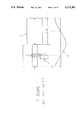
- FIG. 1shows an ultrasonic transducer 1 attached to a horn 2.
- the design and operation of such transducers, powered by piezoelectric crystals 3is well known (see, e.g., Neppiras, Ultrasonics International 1973 Conf. Proc., pp. 295-302).
- Both the transducer and hornare designed to resonate at the same frequency, in which case an extension, ⁇ , produced by the transducer at its ends is communicated to the horn. Since the horn is tuned to the same frequency as the transducer, it expands and contracts along its length in concert with the imposed motion.
- the motion produced at the free face of the hornis then reciprocal, or back and forth in the plane of the page, with an amplitude determined by the electrical voltage 4 applied to the transducer crystals.
- the diagram in FIG. 1shows the variation 12 of extension, ⁇ , along the length of the structure.
- Vibration of any rigid structureis always accompanied by stress. Because the piezoelectric crystals are fabricated from ceramic material they have a very limited tolerance to cyclic stress. For example, metals such as stainless steel or titanium can tolerate an indefinite number of cycles of tension and compression at levels from 10,000 to 40,000 psi. Ceramics, however, can not be exposed to cyclic stress much above 3,000 psi without the production of substantial internal heating and fracture. This limit is particularly pronounced when the stress is produced at ultrasonic frequencies ( ⁇ 18 kHz). In the half wave design shown in FIG. 1, the maximum stress occurs in the crystals, limiting therefore the maximum extension, ⁇ , to about 0.001 inch, p-p (peak to peak) at a frequency of 20 kHz.
- the horn facevibrate with amplitudes in the range of 0.003 to 0.006 inch, p-p.
- vibration amplitudes0.003 to 0.0004 inch, p-p, are commonly used.
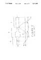
- FIG. 2shows one such transformer or booster horn 5.
- This hornwhich is interposed between the transducer 6 and the working horn 7, and serves to multiply the extension produced by the transducer by a number greater than one.
- the transducer 6, booster horn 5 and working horn 7are each designed to have the same resonant frequency.
- Many designsare available for such boosters and they have been thoroughly reviewed with respect to geometry and performance by others (see, e.g., Eisner, Physical Acoustics, 1964, pp. 353-363).
- the booster shown in FIG. 2is a "stepped" horn in which two solids of constant, but different, cross sectional areas are joined in the region 13 of minimal extension.
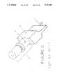
- the input extension 9 produced by the transducer 8is amplified by the horn 10 to produce an increase in output extension at the working face 11.
- This horn 10is also of the stepped design.
- Ultrasonic vibration produced by the structures shown in FIGS. 1 to 3have been commercially applied to continuous industrial processes include laminating, wet or dry cleaning, atomizing, machining or drilling, rolling, densification, grinding, deburring, dewatering, soldering, welding, cutting and the like.
- the Emsinger text referred to aboveprovides additional details of such processes which need not be repeated here.
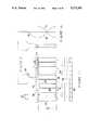
- FIG. 4shows a rectangular structure subjected to a stress, ⁇ , in the direction shown. In a resonator this stress will be a function of the vertical dimension, x. Hence ⁇ , is shown as ⁇ (x). This stress produces a lateral contraction ⁇ that is proportional to ⁇ and the lateral coordinate, w.
- the constant of proportionalityis known as Poisson's Ratio.
- FIG. 5shows the form of motion along the perimeter of the horn that results from a combination of vertical and lateral motion.
- the width of the hornis much smaller than its length, lateral contraction and dilation changes very little the direction and magnitude of the essentially vertical oscillation.
- lateral motionbecomes substantial and begins to contribute a tangential component to the movement of the horn's surfaces.
- the widthis made equal to ⁇ /2 lateral resonance occurs as shown in FIG. 6. Under this condition, the motion of the horn face varies from purely extensional at its center to velocity directed at a 45 degree angle to the face at its ends.
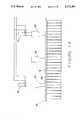
- FIG. 7illustrates a slotted horn attached to a booster 43.
- the slotsare placed at regular intervals ⁇ /6 apart, giving an overall horn width of 7 ⁇ /6, or slightly more than one wavelength.
- the motion imposed at the booster connection 44is purely extensional.
- the unslotted upper and lower regions of hornare not perfectly rigid they do not communicate this motion faithfully to the other portions of the horn which are separated by the slots. Again, a tangential component of motion appears along the horn's edges as shown by arrows 45. The actual displacement of the horn is shown by envelopes for expansion 46 and contraction 47.
- the slotted hornpermits essentially extensional resonance to occur in horns having widths exceeding ⁇ /2, it does not provide a uniform output across the horn face. Variations in the extensional component of motion in such horns are commonly observed to be on the order of 100 percent.
- Such extended width hornswould provide operational advantages in a wide variety of commercial processes, primarily in applications where material having an extended width must be subjected to ultrasonic vibration for a particular process purpose. Such advantages are obtained for processes which utilize the extended width horn in a stationary position over which the material would pass, or for situations when the extended width horn is moved across the surface of a material to be treated.
- a major disadvantage as to the use of ultrasonic transducers for continuous processingrelates to the removal of heat generated by the vibrating piezoelectric crystals.
- the perimeter of the crystalmust be exposed to the atmosphere in order to allow the air to cool the crystal.
- the transduceris open to contact by moisture or fluid if used in a wet environment, with short circuiting or other damage to the crystal being possible.
- the inventionrelates to a vibration apparatus comprising means for generating vibrations in a first direction, and a spine member having first and second ends and being operatively associated with the vibration generating means.
- the spine memberis oriented perpendicular to the direction of the generated vibrations.
- a plurality of tine memberseach having a working end for transmitting the generated vibrations.
- Each tine memberextends perpendicularly from the spine member in the direction of the generated vibrations, and is positioned and attached at an antinode location along the spine member.
- Each tine membershould have a length of n ⁇ /2 wherein n is an integer and ⁇ is equal to c/f where c is the velocity of sound in the apparatus and f is the chosen frequency of vibration.
- first and second tine members positioned on the spine member opposite the attachment of the vibration generation meansare attached at their working end but are otherwise separated by a space extending along their length. Every other tine member is connected to adjacent tine members only at a points along their length of n ⁇ /4 wherein n is an odd integer. These other tine members form a symmetrical pattern on each side of a plane passing vertically between the first and second tine members.
- each tine member other than the first and second tineis separated from the working end of each adjacent tine members.
- the space between the first and second tine membersis generally in the shape of a T.
- a first portion of adjacent tine members other than the first and second tine membersis spaced by a T shaped slot, each slot having a length of about n ⁇ /4, while the T shaped space between the first and second tine members has a length of about n ⁇ /2.
- the second portions of adjacent tine membersare spaced by an elongated slot, with the first portion of the tine members being adjacent the spine member with the second portion of the tine members being adjacent to their working ends.
- the working end of each tine membermay also have a non-uniform shape, such as one of tapered, rounded, angled, or patterned, to impart other performance characteristics to the apparatus.
- the apparatushas a width of at least 1.2 ⁇ , such as at least 12 inches, for frequencies above 18 kHz.
- each tine memberhas a width of less than one half of the flexual wavelength, and preferably less than 1.414 inches.
- the working end of each separated tine memberincludes a longitudinal space extending at an angle to its width.
- the first and second ends of the spine memberwhich each extend beyond the width of the outermost tine members, may be tapered.
- the length of each tine membermay have a first cross sectional area adjacent the spine member and a second cross sectional area adjacent the working end, with the first cross-sectional area being greater than the second cross sectional area.
- the tine memberswould provide amplification to the generated vibrations.
- the generated vibrationshave a uniformity of ⁇ 10% across the width of the apparatus. This is a significant improvement since the width of the apparatus is increased compared to prior art devices.
- means for boosting the generated vibrationsmay be included, and such boosting means may be located between the vibration generating means and the spine member.
- each tine membermay be positioned and attached at every other antinode location along the spine member so that each tine member vibrates in the same direction, thus forming a unitary working end for the apparatus.
- each tine memberis attached at its working end to each adjacent tine member but is separated therefrom by a slot extending substantially along its length. Again, the slot between adjacent tine members has the shape of a T.
- the apparatusincludes a plurality of half wavelength extensional resonators mounted symmetrically on the spine member.
- a plurality of the membersare attached to the spine member with the space between each tine member having a T shape.
- an odd number of resonatorsis utilized and the vibration generating means is associated with the even numbered resonators. It is also possible to utilize an odd number of resonators wherein the vibration generating means is associated with the odd numbered resonators.
- the T shaped space between tine members opposite the resonators associated with the vibration meansis of a longer length than the T shaped space between other tine members.
- the working end of the other tine membersis separated from that of adjacent tine members as described above.
- the term "associated" used in connection with the relationship between the vibration generating means and the resonatorsrefers to whether or not the resonators are vibrated.
- the vibration generating means associated with a resonatorwould be a separate ultrasonic transducer mounted upon the resonator.
- the vibration generating meansis associated with a predetermined number of resonators.
- a preferred arrangementis obtained when the vibration generating means is associated with each resonator.
- the spine membermay have a smaller thickness than it has in the other embodiments by connecting the tines at every other antinode.
- each T shaped space between adjacent tine membershas substantially the same length.
- Another aspect of the inventionrelates to a vibration generating apparatus comprising a plurality of piezoelectric crystals in adjacent spatial relation, means for energizing the crystals in a manner which causes vibration thereof a support for transmitting vibrations generated by the crystals, means for mechanically coupling the crystals to the support, and means for removing heat caused by vibration of the crystals.
- the plurality of crystalscomprises a number of pairs of stacked piezoelectric disks with means disposed between each pair of stacked disks for providing an electrical connection to one side of each disk.
- the electrical connection meanscomprises a metallic electrode.
- Each of these stacked disksincludes a central aperture and the mechanical coupling means comprises an elongated member having a head portion of a cross-section which is larger than that of the disk apertures, a body portion capable of passing through the disk apertures, and a forward end for attachment to the support, thus fastening the disks thereto.
- the heat removing meansmay be an enclosure mounted upon the support and positioned about the crystals, which includes a heat transfer medium contained therewithin.
- the most preferred heat transfer mediumis boron nitride powder, and the enclosure may include a plurality of fin members for dissipating heat.
- the enclosuremay include a jacket for forming a sealed fluid passage for cooling the powder.
- a cooling coil within the enclosuremay also be used, although such a construction is not preferred.
- the inventionalso relates to a cleaning apparatus comprising one of the vibration generating apparatus described above, means for dispensing a cleaning solution adjacent a first side of the vibration generating apparatus toward an item to be cleaned, and means for removing the cleaning solution from the item to be cleaned.
- the removing meansis located adjacent a second the of the vibration generating apparatus and the cleaning solution is dispensed upon the item prior to contact by the vibration generating apparatus and then is removed from the item after contact by the vibration generating apparatus.
- the dispensing meansis a nozzle and the removing means includes a vacuum source.
- a method for subjecting at least one material having a width of at least about 12 inches to ultrasonic vibrationscomprises constructing a unitary vibration generating apparatus having a width which is substantially the same as the material to be treated, generating vibrations from the vibration generating apparatus which do not vary by more than ⁇ 10% across the width, and passing the material between the vibration generating apparatus and a support member to subject a portion of the material to the ultrasonic vibrations.
- the materialmay comprise two separate sheet materials which can be at least partially bonded together.
- the support membermay be a rotating element and at least a portion of the material can be compressed between the rotating element and vibration generating apparatus.
- the methodfurther comprises at least partially laminating these sheet materials together.
- one of the rotating element or vibration generating apparatusmay include a pattern which is imparted to the laminate.
- the methodis also useful wherein the material is discontinuous, and it further comprises forming the material as an integral sheet by passing the vibrations through the discontinuous material.
- the methodmay be used to cut the material in one or more locations as the material passes between or along the vibration generation apparatus and support member.
- this methodmay include separating the liquid component from the solid component as the material passes between the vibration generation apparatus and the support member.
- the support membermay be spaced by a predetermined distance from the material, and vacuum may be applied to the support to assist in the separation of the liquid component from the solid component.
- the methodmay further comprise conveying the fibers to the vibration generating apparatus and forming a fabric as the fibers pass between the vibration generating apparatus and support member. Also, a pattern may be imparted into the fabric, if desired.
- Another methodincludes constructing the support member as a rotating element in combination with means for scraping the material from the rotating element.
- the methodmay further comprise atomizing the material into particles as it passes by the rotating element, scraping means and vibration generating apparatus.
- the methodmay include finishing the metal sheet to a final dimension and condition. This finishing step may include one or more of rolling, grinding, deburring, machining or cleaning the material.
- the materialmay be a particulate solid of metal or otherwise, and the method further comprises compacting the particulate solid as it passes between or along the vibration generating apparatus and support member.
- the method of joining two sheets of material as they pass between the vibration generating apparatus and support membercan also be achieved by this method. These sheets may be welded or soldered together by passing between the vibration generating apparatus and support member.
- Another aspect to the methodrelates to cleaning the material as it passes between the vibration generating apparatus and support member.
- a liquidmay be applied to the material before or as it passes between said vibration generating apparatus and support member, and the applied liquid may be removed as or after the material passes between the vibration generating apparatus and support member.
- FIG. 1is a schematic illustration of a conventional ultrasonic transducer and the variation of extension produced along the length of the device;
- FIG. 2is a schematic illustration of a conventional transducer and booster assembly also illustrating the variation of extension produced along the length of the device;
- FIG. 3is a perspective view of an ultrasonic transducer assembly which includes a stepped working horn;
- FIGS. 4-6are schematic illustrations of solid rectangular structures which are subjected to vibrational stress
- FIG. 7is an illustration of a conventional ultrasonic horn
- FIG. 8is a schematic illustration of various modes of flexural resonance for beams of different thicknesses
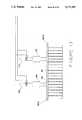
- FIG. 9is a front view of an ultrasonic horn in accordance with the teachings of the invention.
- FIG. 10is a side view of the horn of FIG. 9;
- FIG. 11is a bottom view of the horn of FIG. 9;
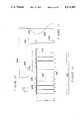
- FIG. 12is a perspective view of another ultrasonic horn according to the invention.
- FIG. 13is an exploded view of the piezoelectric crystals which drive the ultrasonic horn of FIG. 12;
- FIG. 14is a front view of an extended width ultrasonic horn according to the invention which includes both operational and idle resonators;
- FIG. 15is a front view of an extended width ultrasonic horn according to the invention using dual operational resonators
- FIG. 16is a front view of an extended width ultrasonic horn according to the invention where the tines are attached at every other spine antinode;
- FIG. 17is a side view of the horn of FIG. 16;
- FIG. 18is a bottom view of the horn of FIG. 16;
- FIG. 19is a view, partially in cross section, of a preferred piezoelectric crystal configuration for the transducers associated with the operational resonators of the invention.
- FIG. 20is a view, partially in cross section, of a fluid cooled housing for the piezoelectric crystal configuration of FIG. 19;
- FIG. 21is a top view of the housing of FIG. 20;
- FIG. 22is a side view of the housing of FIG. 20;
- FIG. 23is a view, partially in cross section, of an air cooled housing for the crystal configuration of FIG. 19;
- FIG. 24is a side view of the housing of FIG. 23;
- FIG. 25is a side view of the housing of FIG. 23;
- FIG. 26is a perspective view of an apparatus for forming a fabric from raw fibers using an ultrasonic horn according to the invention.
- FIG. 27is a perspective view of an apparatus for drying a fluid laden web which includes an ultrasonic horn according to the invention.
- FIG. 28is a perspective view of an ultrasonic cleaning device according to the invention.
- FIG. 29is a perspective view of an apparatus for atomizing solid material utilizing an ultrasonic horn according to the invention.
- the present inventionachieves an ultrasonic horn which can generate uniform vibrations over a width of ⁇ or greater.
- the horns of the inventionare useful over a frequency range of between 10 and 50 kHz, although ultrasonic frequencies of above 18 to 40 kHz are preferred.
- the width of the devicecan be 10" or greater, with 12 or up to 16" or more easily being achieved in a device which is suitable for continuous operation.
- FIG. 8shows a large mass 48 supporting cantilevered beams 51, each of the same length L but of different thickness T. If this mass is caused to oscillate up and down in the plane of the page as shown 49, a frequency of oscillation will be found where the beams execute the motion shown by curves 52.
- This deformationis produced by standing waves whose wavelength, ⁇ f , bears a direct relation to beam's length, L.
- ⁇ fis also a function of the beam thickness. Consequently, beams of different thickness will execute different motions when excited at the same frequency.
- there are specific frequencieswhere each of the deformation patterns shown in FIG. 8 can be obtained. Each of these patterns is a mode.
- FIG. 8illustrates the first six modes of flexural resonance in a cantilevered beam driven by oscillation at its attachment. All modes are characterized by at least one point of no motion 54, termed a flexural node, and, except for the first mode, at least one point of maximum motion 53 where the slope of the deflection is zero, termed a flexural antinode.
- the vibrational motion at the antinodesis perpendicular to the beam. If a working horn is attached to the beam at any of these points, and its resonant frequency equal to that of the beam, this flexural motion will excite extensional vibration in the horn, acting exactly as does a booster or transducer at its point of attachment in conventional systems.
- FIGS. 9-11illustrates how the flexural resonance of a bar can be used to equitably distribute excitation to an array of extensionally resonant horns.
- the beam 56is an integral part of the booster 55.
- the beamis fabricated as a separate part and attached by a bolt 67 to the booster.
- the booster and the portion of the beam in direct contact with the boosterform an extensionally resonant structure.
- the two portions of the beam whose surfaces are not in contact with the boosterform flexural resonators called a spine member or spine 56.
- the thickness, T, and length, L, of these spinesare adjusted so that they resonate in a given mode at the same frequency as the booster with the beam portion attachment.
- the spine deformation shown 58is the fifth flexural mode disclosed in FIG. 8.
- ⁇ f /2represents half a fifth mode flexural wavelength in the spine, and is substantially equal to the distance between nodes and antinodes.
- extensional hornsare attached to the spine at each antinode 59.
- These horns 60are called tine members or tines in this specification.
- Eachis one half wave of a first mode extensional wavelength, ⁇ 1 , in length.
- the center two tinesare not driven by the spine, but directly from the booster and beam portion. Because the motion of adjacent antinodes is opposite 61, the tines cannot be joined at their output face, nor anywhere else except at their own nodes.
- diagonal slits 62are made through the material joining the tines and into the separating slot 90.
- the slitscan be made very small, on the order of 0.02 inches. Because the motion of the two center tines is in the same direction, these tines, and only these tines are joined at the output face, 67. Preferably, the width of these tines is less than one half the flexural wavelength ( ⁇ f ) of the system (typically about 2 inches), and more specifically, less than 1.414 inches. The most advantageous tine width is about 1 to 1.2 inches. These dimensions reduce lateral motion due to vibration across the width of the tines to a value which does not affect transmission of vibrations along the length of the tines.
- the tinesare thus suspended from the spine, but, as previously mentioned, with the exception of the two center tines, they can be joined at their motional nodes 63.
- This attachmentis possible because the Poisson induced lateral contraction (dilation) of one tine is exactly in the direction of the lateral dilation (contraction) of the adjacent tine.
- Such jointshave important practical utility in serving to make the overall structure sufficiently rigid to withstand, without appreciable deflection, the forces imposed upon the output face during continuous processing. Because the motion of the center tines is identical, a nodal attachment cannot be made, but, as discussed, it is permissible to join these two horns at their output face.
- the motional pattern of the hornis shown 64 reversing direction at every horn, except for the center region. This reversal in motion has no effect upon ultrasonic processes, such as drying, welding, atomizing or cleaning, where the important characteristic of the vibration is the uniformity of the root mean square value of vibration, which is shown as a line 65.
- the curves shown in the profile view of the horndepict the extension of the booster 75 and of two adjacent tines 76, 77.
- the comb horn of FIGS. 9-11has no amplification.
- spine dimensions L and Tare determined by equation (3). Therefore the tines attached to the last antinodes of the spine have an amplitude some 6.5 percent less than the others. In the interest of providing a uniform vibration amplitude over the entire width of the horn, this diminution at the ends may be remedied by taperinq the spine near its free end.
- FIG. 12illustrates this modification. By reducing the mass of the spine at this point 66, the amplitude of last antinode is increased and can be made equal to the others.
- FIGS. 12-13also illustrate the use of tines with amplification, obtained by a reduction in their cross sectional area in the region of their extensional node 91.
- the spine 68is driven by transducer 93 which contains two piezoelectric crystals 69, 70 sandwiched between and electrode 72. The crystals are driven by an alternating current voltage source as shown.
- the tinesare joined together at their nodes 71 and saw slits 72 in the output face maintain separation of adjacent tines while ensuring uniform exposure of vibration to processed media.
- the two center tinesare not joined at their nodes 73, but because they move in the same direction they can be attached at their output face 74.
- the curve 75depicts the deflection of the spine for this particular comb horn.
- the spine and tines of the apparatusare preferably made of a metal such as aluminum or titanium.
- the apparatusis machined from a solid block of such material in a manner which is known by one skilled in that art.
- FIG. 14illustrates a comb horn in which the analysis summarized by equations (3) and (4) both apply.
- This structureis driven by two transducers 78, 79 and companion boosters 84, 85, since a horn of this width may require more power than can be provided by single source.
- the crystals of each transducerare driven by a common voltage source such that both transducers execute the same motion.
- an idle or dummy extensional resonator 80has been added in the center of the spine 81. Spine deflection is shown by the superimposed curve 82.
- the sections of the spine between the transducers 78, 79 and the idle resonator 80are governed by equation (4). In these regions the antinodes are everywhere equal and tine output amplitude is identical.
- the sections of the spine to the right and leftare governed by equation (3), and so have been tapered at their ends to compensate for the dimunition in vibration that would otherwise be encountered.
- the idle resonatormay be replaced by a transducer and booster, identical to those on its right and left, if the power requirement for a process mandated the use of three sources. Any number of transducers and boosters may be used.
- FIG. 15illustrates dual transducers (178, 179) and boosters (184, 185) upon spine 181 wherein tines are attached at each antinode of the vibration wave 182. Again, the ends of the spine 183A, 183B are tapered.
- the idle resonator of FIG. 14serves to allow the use of a spine having a thickness, T, which is greater than it would be if only the two operational transducers were employed.
- Tthickness
- the spine's mode of vibrationhas to be raised, an accomplishment that can only be attained, for any given frequency, by reducing its thickness and thus its static strength in the face of processing forces imposed upon the face of the horn.
- useful hornscan be produced, for the same width spine, the overall length of the horn is somewhat shorter than for horns which include idle transducers.
- the comb hornlike any other ultrasonic horn, must be mounted into the machinery frame so that the requisite force may be applied to the output face of the horn and thereby on the media being processed.
- the nodal regions of the boostersare normally used for this purpose, since in that part of their structure there is little ultrasonic motion.
- This methodis also the preferred arrangement for holding and applying force to the comb horn.
- the motional node on the dummy resonator 80also serves as an intermediate point of support, resisting deflection that might otherwise occur in the center of the horn and thereby ensuring a uniform distribution of contact pressure with the subject media.
- tines 210 in a comb horn 200to every other spine antinode 205, as shown in FIGS. 16-18.
- every tinevibrates in the same direction, precluding joints at their nodes.
- the tinesmay be integrally attached at the horn face 215 and each T shaped slot 225 between adjacent tines would have essentially the same length and configuration.
- the tines 210since they must span two antinodes, are necessarily of greater width than are those in a comb horn using attachments at every antinode. As a result, Poisson coupled lateral motion will be greater is such a structure and the likelihood of a lateral component in the motion of the tines is therefore increased.
- Resonator 230is attached to spine 235 at threaded stud 240.
- Resonator 230is provided with an aperture having mating threads for reception of stud 240.
- the thickness T of spine 235is approximately 1/4 of the thickness of the spine 68 of the apparatus of FIGS. 12-13. Since the value of ⁇ in equation (2) is doubled, the thickness T for spine 235 must be quartered.
- the operation of the comb horns of the inventionare not specific to any particular transducer, although sandwich type piezoelectric designs are shown in FIGS. 1-3 and 12-18.
- Other piezoelectric transducers using tubular crystals, or stacks of cylindrical crystals as well as magnetostrictive transducersmay be used as motive sources for powering the horn.
- the hornmay also be excited by an ultrasonic transmission line, consisting of multiple wavelength rods or tubes connected remotely to the transducers.
- FIGS. 19-25illustrate a preferred piezoelectric crystal assembly 300 for the transducers of the invention, along with two variations for cooling such crystals.
- boron nitride powder 311is used to fill the space around the crystals 306. Since the crystals are porous, liquid coolants such as glycols in contact with the crystals are not preferred, because they may cause cracking of the crystals during extended operation over time. Suitable boron nitride powders are available from Duramic Products, Inc., Palisades Park, N.J. in a variety of mesh sizes which can be used depending upon the specific size of the device. These powders are preferred because they are not electrically conductive, but have a natural lubricity and a thermal conductivity on the order of copper. Thus, the crystals 306 and powder 311 may be hermetically sealed inside enclosure 325 so that the horns of the invention can be successfully used in wet or moist environments.
- FIGS. 19, 20 and 23illustrate the stacking of four disks of piezoelectric crystals 306 with a metal electrode 326 positioned between each disk. Alternate electrodes 326 are connected to different polarity as shown to provide electrical excitation across the planar surfaces of the disks. The electrical connections terminate at ports 308A and 308B for further connection to a suitable power source.
- the assemblyis held under compression by a central bolt 304 and washer 307 which are connected to support 330.
- the supportis also provided with a shoulder 335, to which an outer housing may be attached at a nodal location where minimal vibration is present.
- FIGS. 20-22illustrate an enclosure 325 which is attached to support 330 at shoulder 325.
- O-rings 303are utilized to further isolate enclosure 325 from vibration.
- Enclosure 325is provided with a plurality of channels 312 on its exterior surface.
- jacket 310is provided about enclosure 325 to form a boundary for channels 312.
- Jacket 310 and enclosure 325are connected by the use of pins 302, and O-rings 301 are included for providing a seal which retains fluids therein.
- a suitable cooling fluidsuch as water or a glycol, can be introduced at port 305A, and passes through channels 312 and interconnection 313 in contact with the outer surface of enclosure 325 to remove heat therefrom.
- the enclosurein turn removes heat from powder 311, which in turn removes heat from vibrating crystals 306.
- These channels 312also pass over the top of enclosure 325 for maximum cooling effect.
- this inventioncan be applied to a horn of any width, employing only as many transducers, singly or in combination, as are necessary to perform the intended function. Further, the output face vibration amplitude may be adjusted through either (1) the use of boosters attached to the transducer and horn or (2) by incorporating amplification into the horn itself. As such, this horn is capable of replacing the several or many separate ultrasonic systems now required in continuous processes. Furthermore, unlike an array of separate ultrasonic stations, this invention provides an exactly uniform output vibration that is adjustable from a single power source operated by a single set of controls.
- a wide variety of processescan be conducted with the ultrasonic comb horns of this invention.
- the greatest advantage for the devices of the inventionis for use in processes which must treat materials having extended widths.
- the horns of the present inventioncan be prepared in any width for such applications, to cover widths to be treated of between 60 to 360 inches or greater.
- the working end of the horncan be provided with any of a wide variety of shapes, including flat, rounded, patterns, ridges, angles, etc. for achieving the intended treatment of the material. When angled working ends are provided, any angle can be used, although certain angles or tapers of 30, 45 or 60 degrees (or 90° multiples thereof) are generally advantageous.
- FIG. 26illustrates the use of the horn 350 similar to that of FIG. 15 except that it includes three ultrasonic transducers 355 and is used to laminate and emboss two separate thermoplastic films 360 and 370.
- These filmswhich may be of the same or different materials such as polyester and polyethylene, are sandwiched together between the array of working horns and a rotating drum 380 revolving about axis 390 in the direction shown.
- the working surface of the hornoverlap due to the diagonal slits described above to ensure complete exposure of the films to vibration.
- the drum surfacemay bear a pattern 385 which is engraved or machined upon its surface.
- FIG. 28shows another application for continuous ultrasonic processing.
- an ultrasonic system 450comprising transducer 455, resonator 457 and horn 460 are applied in combination with the administration of a detergent and vacuum to clean materials such as carpets, wall coverings, upholstery and even clothes.
- the ultrasonic system 450is attached to a vacuum wand 465 and detergent nozzle or jet 470.
- the detergententers the jet via hose 472.
- Vacuum 467is applied to the wand 465.
- the whole assemblyis drawn across the soiled material 475 in the direction D shown.
- FIG. 29shows yet another application of ultrasonic vibration to a continuous process.
- waste 480such as sludge is conveyed on a belt 485 over a drum 490 rotating in the direction shown.
- the wasteis then doctored off the drum by a scraping blade 492 onto the working face of the ultrasonic horn assembly 500, which includes transducer 501, resonator 502 and the horn 503 of FIG. 15.
- the intense vibrationatomizes the waste 480 and expels it in the form of a mist 484 which is directed by an air stream 486 to an incinerator where it is combusted.
- Such ultrasonic atomizationgreatly increases the rate at which the waste dries and converts its solid condition on the belt into a form that, because of greatly increased surface area, can more readily burn.
Landscapes
- Engineering & Computer Science (AREA)
- Mechanical Engineering (AREA)
- Physics & Mathematics (AREA)
- Thermal Sciences (AREA)
- Apparatuses For Generation Of Mechanical Vibrations (AREA)
Abstract
Description
Ω=A Sin h(φα)+B Cos h(φα)+C Sin (φα)+D Cos (φα) (1)
φ=βL/E (2)
Tan (φ)=-Tan h(φ) (3)
Cos (φ)=±1
φ=nπ (4)
Ω=ε Cos (φα) (5)
Area=Ae.sup.-aL
Area=Be.sup.-by.sup.2
Claims (31)
Priority Applications (1)
| Application Number | Priority Date | Filing Date | Title |
|---|---|---|---|
| US07/698,764US5171387A (en) | 1990-01-19 | 1991-05-10 | Ultrasonic comb horn and methods for using same |
Applications Claiming Priority (2)
| Application Number | Priority Date | Filing Date | Title |
|---|---|---|---|
| US07/467,624US5057182A (en) | 1990-01-19 | 1990-01-19 | Ultrasonic comb horn and methods for using same |
| US07/698,764US5171387A (en) | 1990-01-19 | 1991-05-10 | Ultrasonic comb horn and methods for using same |
Related Parent Applications (1)
| Application Number | Title | Priority Date | Filing Date |
|---|---|---|---|
| US07/467,624DivisionUS5057182A (en) | 1990-01-19 | 1990-01-19 | Ultrasonic comb horn and methods for using same |
Publications (1)
| Publication Number | Publication Date |
|---|---|
| US5171387Atrue US5171387A (en) | 1992-12-15 |
Family
ID=27042119
Family Applications (1)
| Application Number | Title | Priority Date | Filing Date |
|---|---|---|---|
| US07/698,764Expired - Fee RelatedUS5171387A (en) | 1990-01-19 | 1991-05-10 | Ultrasonic comb horn and methods for using same |
Country Status (1)
| Country | Link |
|---|---|
| US (1) | US5171387A (en) |
Cited By (52)
| Publication number | Priority date | Publication date | Assignee | Title |
|---|---|---|---|---|
| WO1996033758A1 (en)* | 1995-04-26 | 1996-10-31 | Needle Incinerator Company Limited | Apparatus for disposing of hypodermic needles |
| WO1998028115A1 (en)* | 1996-12-20 | 1998-07-02 | Ima Montagetechnik Gmbh | Method and device for compressing and smoothing surfaces of work pieces made of wood or similar |
| US5811909A (en)* | 1996-01-11 | 1998-09-22 | Wuchinich; David G. | Superthermoelastic resonators |
| US6103325A (en)* | 1994-04-15 | 2000-08-15 | Angelica Corporation | Ultrasonically bonded seam in an autoclavable fabric |
| US6203151B1 (en)* | 1999-06-08 | 2001-03-20 | Hewlett-Packard Company | Apparatus and method using ultrasonic energy to fix ink to print media |
| US6376145B1 (en)* | 2000-10-30 | 2002-04-23 | Xerox Corporation | Ultrasonic drying of saturated porous solids via second sound |
| US20020056589A1 (en)* | 2000-10-17 | 2002-05-16 | Wuchinich David G. | Rolling pin horn |
| US6481493B1 (en)* | 1998-08-04 | 2002-11-19 | Dr. Heilscher Gmbh | Arrangement for heat discharge, particularly for ultrasonic transducers with high performance |
| EP1097869A4 (en)* | 1998-03-23 | 2002-12-11 | ||
| US6551337B1 (en) | 1999-10-05 | 2003-04-22 | Omnisonics Medical Technologies, Inc. | Ultrasonic medical device operating in a transverse mode |
| US20030116291A1 (en)* | 2001-12-21 | 2003-06-26 | Sca Hygiene Products Ab | Method for bonding at least two tissue papers to each other |
| US6660013B2 (en) | 1999-10-05 | 2003-12-09 | Omnisonics Medical Technologies, Inc. | Apparatus for removing plaque from blood vessels using ultrasonic energy |
| US6695782B2 (en) | 1999-10-05 | 2004-02-24 | Omnisonics Medical Technologies, Inc. | Ultrasonic probe device with rapid attachment and detachment means |
| US20040079580A1 (en)* | 2002-10-28 | 2004-04-29 | Manna Ronald R. | Ultrasonic horn |
| US20040084995A1 (en)* | 2002-11-04 | 2004-05-06 | Stegelmann Norman R. | Ultrasonic horn assembly stack component connector |
| US6733451B2 (en) | 1999-10-05 | 2004-05-11 | Omnisonics Medical Technologies, Inc. | Apparatus and method for an ultrasonic probe used with a pharmacological agent |
| US20050028942A1 (en)* | 2002-02-12 | 2005-02-10 | Magnus Rabe | Ultrasound horn |
| US20050209076A1 (en)* | 2002-06-19 | 2005-09-22 | Mars Incorporated | Apparatus for producing scored lines in a film |
| US20060241470A1 (en)* | 2005-03-23 | 2006-10-26 | Misonix Incorporated | Ultrasonic wound debrider probe and method of use |
| DE102005038344A1 (en)* | 2005-08-13 | 2007-02-15 | Tetra Laval Holdings & Finance S.A. | Device for ultrasonic machining of workpieces |
| US20080058775A1 (en)* | 2006-08-29 | 2008-03-06 | Darian Alexander L | Ultrasonic debrider probe and method of use |
| US20080063806A1 (en)* | 2006-09-08 | 2008-03-13 | Kimberly-Clark Worldwide, Inc. | Processes for curing a polymeric coating composition using microwave irradiation |
| US20080155764A1 (en)* | 2006-12-28 | 2008-07-03 | Kimberly-Clark Worldwide, Inc. | Process for dyeing a textile web |
| US20080155763A1 (en)* | 2006-12-28 | 2008-07-03 | Kimberly-Clark Worldwide, Inc. | Process for dyeing a textile web |
| US20080155766A1 (en)* | 2006-12-28 | 2008-07-03 | Kimberly-Clark Worldwide, Inc. | Process for dyeing a textile web |
| US20080156428A1 (en)* | 2006-12-28 | 2008-07-03 | Kimberly-Clark Worldwide, Inc. | Process For Bonding Substrates With Improved Microwave Absorbing Compositions |
| US20080156157A1 (en)* | 2006-12-28 | 2008-07-03 | Kimberly-Clark Worldwide, Inc. | Process For Cutting Textile Webs With Improved Microwave Absorbing Compositions |
| FR2910826A1 (en)* | 2007-01-02 | 2008-07-04 | Sodeva Sa | Device for production of longitudinal ultrasonic acoustic vibrations in user element e.g. tube, comprises electro-acoustic converter with pair of piezo-electric ceramics, and intermediate element between the converter and user element |
| US20080192568A1 (en)* | 2004-05-24 | 2008-08-14 | Dr. Hielscher Gmbh | Method and Device For Introducing Ultrasound Into a Flowable Medium |
| US20080286178A1 (en)* | 2007-05-16 | 2008-11-20 | Steris Inc. | Microbial deactivation apparatus having integrated ultrasonic drying system |
| US7503895B2 (en) | 1999-10-05 | 2009-03-17 | Omnisonics Medical Technologies, Inc. | Ultrasonic device for tissue ablation and sheath for use therewith |
| US20090165223A1 (en)* | 2007-12-27 | 2009-07-02 | Kimberly-Clark Worldwide, Inc. | Process for applying one or more treatment agents to a textile web |
| US20100020646A1 (en)* | 2008-07-24 | 2010-01-28 | Donald Patrick Massa | Ultrasonic transducer with improved method of beam angle control |
| US20100024493A1 (en)* | 2007-01-10 | 2010-02-04 | Seong Hae Jeong | Multiple laundry treating machine |
| US7674300B2 (en) | 2006-12-28 | 2010-03-09 | Kimberly-Clark Worldwide, Inc. | Process for dyeing a textile web |
| US20100208553A1 (en)* | 2008-07-24 | 2010-08-19 | Donald Patrick Massa | Hidden ultrasonic transducer with beam angle control for non-contact target detection systems |
| US7794414B2 (en) | 2004-02-09 | 2010-09-14 | Emigrant Bank, N.A. | Apparatus and method for an ultrasonic medical device operating in torsional and transverse modes |
| US20100320255A1 (en)* | 2009-06-22 | 2010-12-23 | Ultex Corporation | Resonator for joining metal members together utilizing ultrasonic vibration |
| US20100324581A1 (en)* | 2006-12-08 | 2010-12-23 | Alcon, Inc. | Torsional Ultrasound Hand Piece That Eliminates Chatter |
| US20110222975A1 (en)* | 2010-03-11 | 2011-09-15 | Edison Welding Institute, Inc. | Ultrasonic machining module |
| US8207651B2 (en) | 2009-09-16 | 2012-06-26 | Tyco Healthcare Group Lp | Low energy or minimum disturbance method for measuring frequency response functions of ultrasonic surgical devices in determining optimum operating point |
| US20130042960A1 (en)* | 2010-04-30 | 2013-02-21 | Orthodyne Electronics Corporation | Ultrasonic bonding systems and methods of using the same |
| US20130253557A1 (en)* | 2012-03-26 | 2013-09-26 | Dana Llc | Surgical instrument ringing a titanium needle with a node of minimum amplitude in a substantially cylindrical portion of the needle |
| US8790359B2 (en) | 1999-10-05 | 2014-07-29 | Cybersonics, Inc. | Medical systems and related methods |
| US20140249555A1 (en)* | 2011-11-11 | 2014-09-04 | Artech Ultrasonic Systems Ag | Ultrasound cutting device |
| US8905689B2 (en) | 2010-04-29 | 2014-12-09 | Edison Welding Institute | Ultrasonic machining assembly for use with portable devices |
| DE102013217362A1 (en)* | 2013-08-30 | 2015-03-05 | Robert Bosch Gmbh | sensor arrangement |
| WO2015116587A1 (en) | 2014-01-28 | 2015-08-06 | Frito-Lay North America, Inc. | Ultrasonic sonotrode for transversely aligned transducer |
| CN109365713A (en)* | 2018-11-10 | 2019-02-22 | 杭州捷能科技有限公司 | A punch auxiliary device suitable for self-piercing riveting and self-piercing riveting method |
| US11191669B2 (en) | 2012-03-26 | 2021-12-07 | Johnson & Johnson Surgical Vision, Inc. | Tapered structure in a phacoemulsification device for node placement |
| US11197778B2 (en) | 2012-03-26 | 2021-12-14 | Johnson & Johnson Surgical Vision, Inc. | Tapered structure in a phacoemulsification device for node placement |
| US12133816B2 (en) | 2012-03-26 | 2024-11-05 | Johnson & Johnson Surgical Vision, Inc. | Phacoemulsification circuit |
Citations (43)
| Publication number | Priority date | Publication date | Assignee | Title |
|---|---|---|---|---|
| US2242120A (en)* | 1939-07-04 | 1941-05-13 | Simmonds Dev Corp Ltd | Holder for piezoelectric devices |
| US2270922A (en)* | 1938-09-12 | 1942-01-27 | Telefunken Gmbh | Piezoelectric crystal holder |
| US2321358A (en)* | 1941-06-30 | 1943-06-08 | Rca Corp | Art of mounting piezoelectric crystals |
| US3056698A (en)* | 1959-11-02 | 1962-10-02 | Cavitron Ultrasonics Inc | Method and apparatus for cleaning porous objects |
| US3089790A (en)* | 1960-06-09 | 1963-05-14 | Cavitron Ultrasonics Inc | Ultrasonic cleaning devices and method of cleaning |
| US3113225A (en)* | 1960-06-09 | 1963-12-03 | Cavitron Ultrasonics Inc | Ultrasonic vibration generator |
| US3524085A (en)* | 1968-05-09 | 1970-08-11 | Branson Instr | Sonic transducer |
| US3660186A (en)* | 1969-04-08 | 1972-05-02 | Kimberly Clark Co | Method for bonding webs employing ultrasonic energy |
| US3939033A (en)* | 1974-12-16 | 1976-02-17 | Branson Ultrasonics Corporation | Ultrasonic welding and cutting apparatus |
| US4011474A (en)* | 1974-10-03 | 1977-03-08 | Pz Technology, Inc. | Piezoelectric stack insulation |
| US4012647A (en)* | 1974-01-31 | 1977-03-15 | Ultrasonic Systems, Inc. | Ultrasonic motors and converters |
| US4044174A (en)* | 1970-09-03 | 1977-08-23 | Eastman Kodak Company | Ultrasonically smoothing a magnetic layer on a web |
| US4069541A (en)* | 1976-04-23 | 1978-01-24 | U.S. Floor Systems, Inc. | Cleaning method and apparatus |
| US4225803A (en)* | 1975-07-04 | 1980-09-30 | Goof Sven Karl Lennart | Apparatus for removing material coatings from interior surfaces of containers |
| US4315181A (en)* | 1980-04-22 | 1982-02-09 | Branson Ultrasonics Corporation | Ultrasonic resonator (horn) with skewed slots |
| US4326903A (en)* | 1980-12-05 | 1982-04-27 | Branson Ultrasonics Corporation | Method for securing parts together by ultrasonic energy |
| US4334168A (en)* | 1979-07-18 | 1982-06-08 | Etat Francais | High frequency, thermostatically self controlled oscillator |
| US4352570A (en)* | 1980-05-27 | 1982-10-05 | Applied Plastics Co., Inc. | Vibratory treatment apparatus and method |
| US4356590A (en)* | 1980-07-31 | 1982-11-02 | Aaron Goldsmith | Carpet cleaning system |
| US4363992A (en)* | 1981-01-26 | 1982-12-14 | Branson Ultrasonics Corporation | Resonator exhibiting uniform motional output |
| US4385413A (en)* | 1980-06-24 | 1983-05-31 | Aaron Goldsmith | Carpet cleaning system |
| US4414045A (en)* | 1982-02-22 | 1983-11-08 | Burlington Industries, Inc. | High speed ultrasonic bonding |
| US4483571A (en)* | 1982-05-12 | 1984-11-20 | Tage Electric Co., Ltd. | Ultrasonic processing device |
| US4529115A (en)* | 1983-04-12 | 1985-07-16 | Fairchild Industries, Inc. | Thermally assisted ultrasonic welding apparatus and process |
| US4530138A (en)* | 1982-09-30 | 1985-07-23 | Westinghouse Electric Corp. | Method of making a transducer assembly |
| US4534819A (en)* | 1983-11-28 | 1985-08-13 | Springs Industries, Inc. | Woven textile fabric having an ultrasonically cut and sealed edge and apparatus and process for producing same |
| US4583365A (en)* | 1979-08-23 | 1986-04-22 | Georgina C. Hirtle | Reticulated electrothermal fluid motor |
| US4605454A (en)* | 1982-09-01 | 1986-08-12 | Kimberly-Clark Corporation | Method of ultrasonically bonding nonwoven webs |
| US4607185A (en)* | 1985-02-01 | 1986-08-19 | American Hospital Supply Corporation | Ultrasonic horn assembly |
| US4633119A (en)* | 1984-07-02 | 1986-12-30 | Gould Inc. | Broadband multi-resonant longitudinal vibrator transducer |
| US4647336A (en)* | 1985-03-08 | 1987-03-03 | Kimberly-Clark Corporation | Rebuildable support assembly |
| US4651043A (en)* | 1985-10-23 | 1987-03-17 | Branson Ultrasonics Corporation | Resonator exhibiting uniform motional output |
| US4652785A (en)* | 1983-09-20 | 1987-03-24 | Skoda, Koncernovy Podnik | Acoustic piezoelectric power transducer |
| US4690722A (en)* | 1986-10-24 | 1987-09-01 | Branson Ultrasonics Corporation | Ultrasonic apparatus for joining and severing sheet material |
| US4713132A (en)* | 1986-05-08 | 1987-12-15 | Kimberly-Clark Corporation | Apparatus and method for ultrasonic bonding of a moving web |
| US4715078A (en)* | 1982-11-29 | 1987-12-29 | Web Systems, Inc. | Paperboard edge buffer and cleaner |
| US4749437A (en)* | 1987-04-06 | 1988-06-07 | American Technology, Inc. | Variably-weighted ultrasonic welding horn |
| US4750488A (en)* | 1986-05-19 | 1988-06-14 | Sonomed Technology, Inc. | Vibration apparatus preferably for endoscopic ultrasonic aspirator |
| US4758293A (en)* | 1986-06-25 | 1988-07-19 | Kimberly-Clark Corporation | Ultrasonic bonding apparatus and method |
| US4762668A (en)* | 1986-04-24 | 1988-08-09 | Westinghouse Electric Corp. | Venturi flow nozzle ultrasonic cleaning device |
| US4770730A (en)* | 1987-09-29 | 1988-09-13 | Tachi-S. Co., Ltd. | Ultrasonic welding method for soft elastic foam body |
| US4823783A (en)* | 1986-02-28 | 1989-04-25 | The Procter & Gamble Company | Adhesive-free bonding of continuously moving webs to form laminate web and products cut therefrom |
| US4885499A (en)* | 1988-02-12 | 1989-12-05 | Ngk Spark Plug Co., Inc. | Ultrasonic driven type motor |
- 1991
- 1991-05-10USUS07/698,764patent/US5171387A/ennot_activeExpired - Fee Related
Patent Citations (43)
| Publication number | Priority date | Publication date | Assignee | Title |
|---|---|---|---|---|
| US2270922A (en)* | 1938-09-12 | 1942-01-27 | Telefunken Gmbh | Piezoelectric crystal holder |
| US2242120A (en)* | 1939-07-04 | 1941-05-13 | Simmonds Dev Corp Ltd | Holder for piezoelectric devices |
| US2321358A (en)* | 1941-06-30 | 1943-06-08 | Rca Corp | Art of mounting piezoelectric crystals |
| US3056698A (en)* | 1959-11-02 | 1962-10-02 | Cavitron Ultrasonics Inc | Method and apparatus for cleaning porous objects |
| US3089790A (en)* | 1960-06-09 | 1963-05-14 | Cavitron Ultrasonics Inc | Ultrasonic cleaning devices and method of cleaning |
| US3113225A (en)* | 1960-06-09 | 1963-12-03 | Cavitron Ultrasonics Inc | Ultrasonic vibration generator |
| US3524085A (en)* | 1968-05-09 | 1970-08-11 | Branson Instr | Sonic transducer |
| US3660186A (en)* | 1969-04-08 | 1972-05-02 | Kimberly Clark Co | Method for bonding webs employing ultrasonic energy |
| US4044174A (en)* | 1970-09-03 | 1977-08-23 | Eastman Kodak Company | Ultrasonically smoothing a magnetic layer on a web |
| US4012647A (en)* | 1974-01-31 | 1977-03-15 | Ultrasonic Systems, Inc. | Ultrasonic motors and converters |
| US4011474A (en)* | 1974-10-03 | 1977-03-08 | Pz Technology, Inc. | Piezoelectric stack insulation |
| US3939033A (en)* | 1974-12-16 | 1976-02-17 | Branson Ultrasonics Corporation | Ultrasonic welding and cutting apparatus |
| US4225803A (en)* | 1975-07-04 | 1980-09-30 | Goof Sven Karl Lennart | Apparatus for removing material coatings from interior surfaces of containers |
| US4069541A (en)* | 1976-04-23 | 1978-01-24 | U.S. Floor Systems, Inc. | Cleaning method and apparatus |
| US4334168A (en)* | 1979-07-18 | 1982-06-08 | Etat Francais | High frequency, thermostatically self controlled oscillator |
| US4583365A (en)* | 1979-08-23 | 1986-04-22 | Georgina C. Hirtle | Reticulated electrothermal fluid motor |
| US4315181A (en)* | 1980-04-22 | 1982-02-09 | Branson Ultrasonics Corporation | Ultrasonic resonator (horn) with skewed slots |
| US4352570A (en)* | 1980-05-27 | 1982-10-05 | Applied Plastics Co., Inc. | Vibratory treatment apparatus and method |
| US4385413A (en)* | 1980-06-24 | 1983-05-31 | Aaron Goldsmith | Carpet cleaning system |
| US4356590A (en)* | 1980-07-31 | 1982-11-02 | Aaron Goldsmith | Carpet cleaning system |
| US4326903A (en)* | 1980-12-05 | 1982-04-27 | Branson Ultrasonics Corporation | Method for securing parts together by ultrasonic energy |
| US4363992A (en)* | 1981-01-26 | 1982-12-14 | Branson Ultrasonics Corporation | Resonator exhibiting uniform motional output |
| US4414045A (en)* | 1982-02-22 | 1983-11-08 | Burlington Industries, Inc. | High speed ultrasonic bonding |
| US4483571A (en)* | 1982-05-12 | 1984-11-20 | Tage Electric Co., Ltd. | Ultrasonic processing device |
| US4605454A (en)* | 1982-09-01 | 1986-08-12 | Kimberly-Clark Corporation | Method of ultrasonically bonding nonwoven webs |
| US4530138A (en)* | 1982-09-30 | 1985-07-23 | Westinghouse Electric Corp. | Method of making a transducer assembly |
| US4715078A (en)* | 1982-11-29 | 1987-12-29 | Web Systems, Inc. | Paperboard edge buffer and cleaner |
| US4529115A (en)* | 1983-04-12 | 1985-07-16 | Fairchild Industries, Inc. | Thermally assisted ultrasonic welding apparatus and process |
| US4652785A (en)* | 1983-09-20 | 1987-03-24 | Skoda, Koncernovy Podnik | Acoustic piezoelectric power transducer |
| US4534819A (en)* | 1983-11-28 | 1985-08-13 | Springs Industries, Inc. | Woven textile fabric having an ultrasonically cut and sealed edge and apparatus and process for producing same |
| US4633119A (en)* | 1984-07-02 | 1986-12-30 | Gould Inc. | Broadband multi-resonant longitudinal vibrator transducer |
| US4607185A (en)* | 1985-02-01 | 1986-08-19 | American Hospital Supply Corporation | Ultrasonic horn assembly |
| US4647336A (en)* | 1985-03-08 | 1987-03-03 | Kimberly-Clark Corporation | Rebuildable support assembly |
| US4651043A (en)* | 1985-10-23 | 1987-03-17 | Branson Ultrasonics Corporation | Resonator exhibiting uniform motional output |
| US4823783A (en)* | 1986-02-28 | 1989-04-25 | The Procter & Gamble Company | Adhesive-free bonding of continuously moving webs to form laminate web and products cut therefrom |
| US4762668A (en)* | 1986-04-24 | 1988-08-09 | Westinghouse Electric Corp. | Venturi flow nozzle ultrasonic cleaning device |
| US4713132A (en)* | 1986-05-08 | 1987-12-15 | Kimberly-Clark Corporation | Apparatus and method for ultrasonic bonding of a moving web |
| US4750488A (en)* | 1986-05-19 | 1988-06-14 | Sonomed Technology, Inc. | Vibration apparatus preferably for endoscopic ultrasonic aspirator |
| US4758293A (en)* | 1986-06-25 | 1988-07-19 | Kimberly-Clark Corporation | Ultrasonic bonding apparatus and method |
| US4690722A (en)* | 1986-10-24 | 1987-09-01 | Branson Ultrasonics Corporation | Ultrasonic apparatus for joining and severing sheet material |
| US4749437A (en)* | 1987-04-06 | 1988-06-07 | American Technology, Inc. | Variably-weighted ultrasonic welding horn |
| US4770730A (en)* | 1987-09-29 | 1988-09-13 | Tachi-S. Co., Ltd. | Ultrasonic welding method for soft elastic foam body |
| US4885499A (en)* | 1988-02-12 | 1989-12-05 | Ngk Spark Plug Co., Inc. | Ultrasonic driven type motor |
Non-Patent Citations (10)
| Title |
|---|
| Eisner, Physical Acoustics, 1964, pp. 353 363.* |
| Eisner, Physical Acoustics, 1964, pp. 353-363. |
| Emsinger, Ultrasonics, 1988, pp. 419 492.* |
| Emsinger, Ultrasonics, 1988, pp. 419-492. |
| Neppiras, The Pre Stressed Piezoelectric Sandwich Transducer, 1973, pp. 295 302.* |
| Neppiras, The Pre-Stressed Piezoelectric Sandwich Transducer, 1973, pp. 295-302. |
| Rayleigh, The Theory of Sound, vol. 1., 1894, pp. 255 305.* |
| Rayleigh, The Theory of Sound, vol. 1., 1894, pp. 255-305. |
| Rozenberg, Sources of High Intensity Ultrasound, vol. 2., 1973, pp. 111 114.* |
| Rozenberg, Sources of High-Intensity Ultrasound, vol. 2., 1973, pp. 111-114. |
Cited By (94)
| Publication number | Priority date | Publication date | Assignee | Title |
|---|---|---|---|---|
| US6103325A (en)* | 1994-04-15 | 2000-08-15 | Angelica Corporation | Ultrasonically bonded seam in an autoclavable fabric |
| US6148742A (en)* | 1995-04-26 | 2000-11-21 | Needle Incinerator Company Limited | Apparatus for disposing of hypodermic needles |
| WO1996033758A1 (en)* | 1995-04-26 | 1996-10-31 | Needle Incinerator Company Limited | Apparatus for disposing of hypodermic needles |
| US5811909A (en)* | 1996-01-11 | 1998-09-22 | Wuchinich; David G. | Superthermoelastic resonators |
| WO1998028115A1 (en)* | 1996-12-20 | 1998-07-02 | Ima Montagetechnik Gmbh | Method and device for compressing and smoothing surfaces of work pieces made of wood or similar |
| US6605178B1 (en) | 1998-03-23 | 2003-08-12 | Shikoku Kakoki Co., Ltd. | Ultrasonic sealer |
| EP1097869A4 (en)* | 1998-03-23 | 2002-12-11 | ||
| US6481493B1 (en)* | 1998-08-04 | 2002-11-19 | Dr. Heilscher Gmbh | Arrangement for heat discharge, particularly for ultrasonic transducers with high performance |
| US6203151B1 (en)* | 1999-06-08 | 2001-03-20 | Hewlett-Packard Company | Apparatus and method using ultrasonic energy to fix ink to print media |
| US6431702B2 (en) | 1999-06-08 | 2002-08-13 | Hewlett-Packard Company | Apparatus and method using ultrasonic energy to fix ink to print media |
| US6660013B2 (en) | 1999-10-05 | 2003-12-09 | Omnisonics Medical Technologies, Inc. | Apparatus for removing plaque from blood vessels using ultrasonic energy |
| US6551337B1 (en) | 1999-10-05 | 2003-04-22 | Omnisonics Medical Technologies, Inc. | Ultrasonic medical device operating in a transverse mode |
| US7494468B2 (en) | 1999-10-05 | 2009-02-24 | Omnisonics Medical Technologies, Inc. | Ultrasonic medical device operating in a transverse mode |
| US20030125645A1 (en)* | 1999-10-05 | 2003-07-03 | Omnisonics Medical Technologies, Inc. | Ultrasonic medical device operating in a transverse mode |
| US6695782B2 (en) | 1999-10-05 | 2004-02-24 | Omnisonics Medical Technologies, Inc. | Ultrasonic probe device with rapid attachment and detachment means |
| US20040073244A1 (en)* | 1999-10-05 | 2004-04-15 | Omnisonics Medical Technologies, Inc. | Method and apparatus for removing plaque from blood vessels using ultrasonic energy |
| US7503895B2 (en) | 1999-10-05 | 2009-03-17 | Omnisonics Medical Technologies, Inc. | Ultrasonic device for tissue ablation and sheath for use therewith |
| US8790359B2 (en) | 1999-10-05 | 2014-07-29 | Cybersonics, Inc. | Medical systems and related methods |
| US6733451B2 (en) | 1999-10-05 | 2004-05-11 | Omnisonics Medical Technologies, Inc. | Apparatus and method for an ultrasonic probe used with a pharmacological agent |
| US6866670B2 (en) | 1999-10-05 | 2005-03-15 | Omnisonics Medical Technologies, Inc. | Apparatus for removing plaque from blood vessels using ultrasonic energy |
| US20020056589A1 (en)* | 2000-10-17 | 2002-05-16 | Wuchinich David G. | Rolling pin horn |
| US6877975B2 (en) | 2000-10-17 | 2005-04-12 | David G. Wuchinich | Rolling pin horn |
| US6376145B1 (en)* | 2000-10-30 | 2002-04-23 | Xerox Corporation | Ultrasonic drying of saturated porous solids via second sound |
| US20050082022A1 (en)* | 2001-12-21 | 2005-04-21 | Sca Hygiene Products Gmbh | Method for bonding at least two tissue papers to each other |
| US20030116291A1 (en)* | 2001-12-21 | 2003-06-26 | Sca Hygiene Products Ab | Method for bonding at least two tissue papers to each other |
| US7122097B2 (en)* | 2002-02-12 | 2006-10-17 | Tetra Laval Holdings & Finance S.A. | Ultrasound horn |
| US20050028942A1 (en)* | 2002-02-12 | 2005-02-10 | Magnus Rabe | Ultrasound horn |
| US20050209076A1 (en)* | 2002-06-19 | 2005-09-22 | Mars Incorporated | Apparatus for producing scored lines in a film |
| US7004282B2 (en)* | 2002-10-28 | 2006-02-28 | Misonix, Incorporated | Ultrasonic horn |
| WO2004040530A1 (en)* | 2002-10-28 | 2004-05-13 | Misonix Incorporated | Ultrasonic horn |
| US20040079580A1 (en)* | 2002-10-28 | 2004-04-29 | Manna Ronald R. | Ultrasonic horn |
| US20050110370A1 (en)* | 2002-11-04 | 2005-05-26 | Kimberly-Clark Worldwide, Inc. | Ultrasonic horn assembly stack component connector |
| WO2004041449A1 (en)* | 2002-11-04 | 2004-05-21 | Kimberly-Clark Worldwide, Inc. | Ultrasonic horn assembly stack component connector |
| US20040084995A1 (en)* | 2002-11-04 | 2004-05-06 | Stegelmann Norman R. | Ultrasonic horn assembly stack component connector |
| US20070194661A1 (en)* | 2002-11-04 | 2007-08-23 | Kimberly-Clark Worldwide, Inc. | Ultrasonic Horn Assembly Stack Component Connector Having Threadless Segment |
| US7514846B2 (en) | 2002-11-04 | 2009-04-07 | Kimberly-Clark Worldwide, Inc. | Ultrasonic horn assembly stack component connector having threadless segment |
| US6841921B2 (en) | 2002-11-04 | 2005-01-11 | Kimberly-Clark Worldwide, Inc. | Ultrasonic horn assembly stack component connector |
| US7794414B2 (en) | 2004-02-09 | 2010-09-14 | Emigrant Bank, N.A. | Apparatus and method for an ultrasonic medical device operating in torsional and transverse modes |
| US20080192568A1 (en)* | 2004-05-24 | 2008-08-14 | Dr. Hielscher Gmbh | Method and Device For Introducing Ultrasound Into a Flowable Medium |
| US8235579B2 (en)* | 2004-05-24 | 2012-08-07 | Dr. Hielscher Gmbh | Device for introducing ultrasound into a flowable medium |
| US7931611B2 (en) | 2005-03-23 | 2011-04-26 | Misonix, Incorporated | Ultrasonic wound debrider probe and method of use |
| US20060241470A1 (en)* | 2005-03-23 | 2006-10-26 | Misonix Incorporated | Ultrasonic wound debrider probe and method of use |
| DE102005038344A1 (en)* | 2005-08-13 | 2007-02-15 | Tetra Laval Holdings & Finance S.A. | Device for ultrasonic machining of workpieces |
| US20080058775A1 (en)* | 2006-08-29 | 2008-03-06 | Darian Alexander L | Ultrasonic debrider probe and method of use |
| US20080063806A1 (en)* | 2006-09-08 | 2008-03-13 | Kimberly-Clark Worldwide, Inc. | Processes for curing a polymeric coating composition using microwave irradiation |
| US20100324581A1 (en)* | 2006-12-08 | 2010-12-23 | Alcon, Inc. | Torsional Ultrasound Hand Piece That Eliminates Chatter |
| US8579929B2 (en)* | 2006-12-08 | 2013-11-12 | Alcon Research, Ltd. | Torsional ultrasound hand piece that eliminates chatter |
| US7674300B2 (en) | 2006-12-28 | 2010-03-09 | Kimberly-Clark Worldwide, Inc. | Process for dyeing a textile web |
| US8182552B2 (en) | 2006-12-28 | 2012-05-22 | Kimberly-Clark Worldwide, Inc. | Process for dyeing a textile web |
| US20080155763A1 (en)* | 2006-12-28 | 2008-07-03 | Kimberly-Clark Worldwide, Inc. | Process for dyeing a textile web |
| US20080155766A1 (en)* | 2006-12-28 | 2008-07-03 | Kimberly-Clark Worldwide, Inc. | Process for dyeing a textile web |
| US7568251B2 (en) | 2006-12-28 | 2009-08-04 | Kimberly-Clark Worldwide, Inc. | Process for dyeing a textile web |
| US20080156428A1 (en)* | 2006-12-28 | 2008-07-03 | Kimberly-Clark Worldwide, Inc. | Process For Bonding Substrates With Improved Microwave Absorbing Compositions |
| US20080156157A1 (en)* | 2006-12-28 | 2008-07-03 | Kimberly-Clark Worldwide, Inc. | Process For Cutting Textile Webs With Improved Microwave Absorbing Compositions |
| US20080155764A1 (en)* | 2006-12-28 | 2008-07-03 | Kimberly-Clark Worldwide, Inc. | Process for dyeing a textile web |
| US7740666B2 (en) | 2006-12-28 | 2010-06-22 | Kimberly-Clark Worldwide, Inc. | Process for dyeing a textile web |
| WO2008081360A1 (en)* | 2006-12-28 | 2008-07-10 | Kimberly-Clark Worldwide, Inc. | Process for dyeing a textile web |
| TWI413553B (en)* | 2007-01-02 | 2013-11-01 | Sodeva | Device for producing ultrasonic vibrations |
| FR2910826A1 (en)* | 2007-01-02 | 2008-07-04 | Sodeva Sa | Device for production of longitudinal ultrasonic acoustic vibrations in user element e.g. tube, comprises electro-acoustic converter with pair of piezo-electric ceramics, and intermediate element between the converter and user element |
| WO2008080888A1 (en)* | 2007-01-02 | 2008-07-10 | Heraeus Psp France Sas | Device for producing ultrasonic vibrations |
| US20100024493A1 (en)* | 2007-01-10 | 2010-02-04 | Seong Hae Jeong | Multiple laundry treating machine |
| US8641966B2 (en) | 2007-05-16 | 2014-02-04 | American Sterilizer Company | Method for removing moisture from a container |
| US8420016B2 (en) | 2007-05-16 | 2013-04-16 | American Sterilizer Company | Microbial deactivation apparatus having integrated ultrasonic drying system |
| US20080286178A1 (en)* | 2007-05-16 | 2008-11-20 | Steris Inc. | Microbial deactivation apparatus having integrated ultrasonic drying system |
| US20090165223A1 (en)* | 2007-12-27 | 2009-07-02 | Kimberly-Clark Worldwide, Inc. | Process for applying one or more treatment agents to a textile web |
| US8632613B2 (en) | 2007-12-27 | 2014-01-21 | Kimberly-Clark Worldwide, Inc. | Process for applying one or more treatment agents to a textile web |
| US20100208553A1 (en)* | 2008-07-24 | 2010-08-19 | Donald Patrick Massa | Hidden ultrasonic transducer with beam angle control for non-contact target detection systems |
| US8320218B2 (en)* | 2008-07-24 | 2012-11-27 | Massa Products Corporation | Hidden ultrasonic transducer with beam angle control for non-contact target detection systems |
| US20100020646A1 (en)* | 2008-07-24 | 2010-01-28 | Donald Patrick Massa | Ultrasonic transducer with improved method of beam angle control |
| US8085621B2 (en)* | 2008-07-24 | 2011-12-27 | Massa Products Corporation | Ultrasonic transducer with improved method of beam angle control |
| US20100320255A1 (en)* | 2009-06-22 | 2010-12-23 | Ultex Corporation | Resonator for joining metal members together utilizing ultrasonic vibration |
| US8201722B2 (en)* | 2009-06-22 | 2012-06-19 | Ultex Corporation | Resonator for joining metal members together utilizing ultrasonic vibration |
| US8390169B2 (en) | 2009-09-16 | 2013-03-05 | Covidien Lp | Low energy or minimum disturbance method for measuring frequency response functions of ultrasonic surgical devices in determining optimum operating point |
| US8569925B2 (en) | 2009-09-16 | 2013-10-29 | Covidien Lp | Low energy or minimum disturbance method for measuring frequency response functions of ultrasonic surgical devices in determining optimum operating point |
| US8207651B2 (en) | 2009-09-16 | 2012-06-26 | Tyco Healthcare Group Lp | Low energy or minimum disturbance method for measuring frequency response functions of ultrasonic surgical devices in determining optimum operating point |
| US8870500B2 (en) | 2010-03-11 | 2014-10-28 | Edison Welding Institute | Ultrasonic machining module |
| US20110222975A1 (en)* | 2010-03-11 | 2011-09-15 | Edison Welding Institute, Inc. | Ultrasonic machining module |
| US8905689B2 (en) | 2010-04-29 | 2014-12-09 | Edison Welding Institute | Ultrasonic machining assembly for use with portable devices |
| US8544717B2 (en)* | 2010-04-30 | 2013-10-01 | Orthodyne Electronics Corporation | Ultrasonic bonding systems and methods of using the same |
| US8573468B1 (en) | 2010-04-30 | 2013-11-05 | Orthodyne Electronics Corporation | Ultrasonic bonding systems and methods of using the same |
| US20130042960A1 (en)* | 2010-04-30 | 2013-02-21 | Orthodyne Electronics Corporation | Ultrasonic bonding systems and methods of using the same |
| US20140249555A1 (en)* | 2011-11-11 | 2014-09-04 | Artech Ultrasonic Systems Ag | Ultrasound cutting device |
| US10717204B2 (en)* | 2011-11-11 | 2020-07-21 | Artech Ultrasonic Systems Ag | Ultrasound cutting device |
| US9216035B2 (en)* | 2012-03-26 | 2015-12-22 | Alex Urich | Surgical instrument ringing a titanium needle with a node of minimum amplitude in a substantially cylindrical portion of the needle |
| US20130253557A1 (en)* | 2012-03-26 | 2013-09-26 | Dana Llc | Surgical instrument ringing a titanium needle with a node of minimum amplitude in a substantially cylindrical portion of the needle |
| US11191669B2 (en) | 2012-03-26 | 2021-12-07 | Johnson & Johnson Surgical Vision, Inc. | Tapered structure in a phacoemulsification device for node placement |
| US11197778B2 (en) | 2012-03-26 | 2021-12-14 | Johnson & Johnson Surgical Vision, Inc. | Tapered structure in a phacoemulsification device for node placement |
| US12133816B2 (en) | 2012-03-26 | 2024-11-05 | Johnson & Johnson Surgical Vision, Inc. | Phacoemulsification circuit |
| CN105492924A (en)* | 2013-08-30 | 2016-04-13 | 罗伯特·博世有限公司 | sensor device |
| DE102013217362A1 (en)* | 2013-08-30 | 2015-03-05 | Robert Bosch Gmbh | sensor arrangement |
| US10151828B2 (en) | 2013-08-30 | 2018-12-11 | Robert Bosch Gmbh | Sensor system |
| WO2015116587A1 (en) | 2014-01-28 | 2015-08-06 | Frito-Lay North America, Inc. | Ultrasonic sonotrode for transversely aligned transducer |
| EP3099468A4 (en)* | 2014-01-28 | 2017-09-27 | Edison Welding Institute, Inc. | Ultrasonic sonotrode for transversely aligned transducer |
| CN109365713A (en)* | 2018-11-10 | 2019-02-22 | 杭州捷能科技有限公司 | A punch auxiliary device suitable for self-piercing riveting and self-piercing riveting method |
Similar Documents
| Publication | Publication Date | Title |
|---|---|---|
| US5171387A (en) | Ultrasonic comb horn and methods for using same | |
| US5057182A (en) | Ultrasonic comb horn and methods for using same | |
| KR100415135B1 (en) | Stacked Rotary Sound Horns | |
| KR101095912B1 (en) | Megasonic Processor with Frequency Sweep of Thickness Mode Transducer | |
| US3688527A (en) | Apparatus for cleaning resilient webs | |
| US4315181A (en) | Ultrasonic resonator (horn) with skewed slots | |
| US3490584A (en) | Method and apparatus for high frequency screening of materials | |
| US2891178A (en) | Support for vibratory devices | |
| US9610617B2 (en) | Megasonic multifrequency apparatus with matched transducer | |
| WO2008080888A1 (en) | Device for producing ultrasonic vibrations | |
| KR19990014005A (en) | Ultrasonic devices | |
| Ide et al. | A low-profile design for the noncontact ultrasonically levitated stage | |
| US3829328A (en) | Method for cleaning resilient webs | |
| RU2100313C1 (en) | Method of manufacturing items from powder | |
| JP5245064B2 (en) | ULTRASONIC VIBRATION ELEMENT, ITS MANUFACTURING METHOD, AND ULTRASONIC CLEANING DEVICE | |
| CN112588713A (en) | Contact through type ultrasonic cleaning device | |
| JP2010253948A (en) | Cleaning device | |
| Gallego-Juarez | Transducer needs for macrosonics | |
| JPS6227657B2 (en) | ||
| JPH03232575A (en) | Composite vibration driving method of ultrasonic vibrator | |
| JPH03234498A (en) | Composite vibrating ultrasonic cutter | |
| JPS6224256B2 (en) | ||
| JPS62196000A (en) | Langevin type transducer for high frequency | |
| JP2004179944A (en) | Ultrasonic vibration radiating body | |
| FI60259C (en) | FOERFARANDE OCH APPARAT FOER RENGOERING AV FLEXIBLA BANOR |
Legal Events
| Date | Code | Title | Description |
|---|---|---|---|
| AS | Assignment | Owner name:SONOKINETICS, INC. Free format text:TERMINATING, RELEASE AND REASSIGNMENT OF PATENT ASSETS.;ASSIGNORS:TDW TWO, INC.;DJB TWO, INC.;SONOKINETICS GROUP;REEL/FRAME:006962/0149 Effective date:19940121 | |
| AS | Assignment | Owner name:SONOKINETICS GROUP, NEW JERSEY Free format text:TERMINATION, RELEASE AND REASSIGNMENT OF PATENT ASSETS.;ASSIGNORS:TDW TWO, INC.;DJB TWO, INC.;SONOKINETICS GROUP;REEL/FRAME:006909/0047 Effective date:19940315 Owner name:SONOKINETICS INC., NEW JERSEY Free format text:ASSIGNMENT OF ASSIGNORS INTEREST;ASSIGNOR:SONOKINETICS GROUP;REEL/FRAME:006903/0158 Effective date:19940121 | |
| REMI | Maintenance fee reminder mailed | ||
| LAPS | Lapse for failure to pay maintenance fees | ||
| FPAY | Fee payment | Year of fee payment:4 | |
| SULP | Surcharge for late payment | ||
| FP | Lapsed due to failure to pay maintenance fee | Effective date:19961218 | |
| FPAY | Fee payment | Year of fee payment:8 | |
| FPAY | Fee payment | Year of fee payment:12 | |
| FEPP | Fee payment procedure | Free format text:PAYOR NUMBER ASSIGNED (ORIGINAL EVENT CODE: ASPN); ENTITY STATUS OF PATENT OWNER: SMALL ENTITY | |
| FEPP | Fee payment procedure | Free format text:PAYER NUMBER DE-ASSIGNED (ORIGINAL EVENT CODE: RMPN); ENTITY STATUS OF PATENT OWNER: SMALL ENTITY Free format text:PAYOR NUMBER ASSIGNED (ORIGINAL EVENT CODE: ASPN); ENTITY STATUS OF PATENT OWNER: SMALL ENTITY | |
| STCH | Information on status: patent discontinuation | Free format text:PATENT EXPIRED DUE TO NONPAYMENT OF MAINTENANCE FEES UNDER 37 CFR 1.362 |