US5171245A - Surgical apparatus including a spring activated locking device - Google Patents
Surgical apparatus including a spring activated locking deviceDownload PDFInfo
- Publication number
- US5171245A US5171245AUS07/589,418US58941890AUS5171245AUS 5171245 AUS5171245 AUS 5171245AUS 58941890 AUS58941890 AUS 58941890AUS 5171245 AUS5171245 AUS 5171245A
- Authority
- US
- United States
- Prior art keywords
- tool
- lock
- sleeve
- lock housing
- housing
- Prior art date
- Legal status (The legal status is an assumption and is not a legal conclusion. Google has not performed a legal analysis and makes no representation as to the accuracy of the status listed.)
- Expired - Lifetime
Links
- 230000002093peripheral effectEffects0.000claimsdescription5
- 239000011248coating agentSubstances0.000claims1
- 238000000576coating methodMethods0.000claims1
- 239000007788liquidSubstances0.000description9
- 238000001356surgical procedureMethods0.000description6
- 230000006835compressionEffects0.000description3
- 238000007906compressionMethods0.000description3
- 239000012530fluidSubstances0.000description3
- 239000000463materialSubstances0.000description3
- 238000004891communicationMethods0.000description2
- 230000009969flowable effectEffects0.000description2
- 238000003780insertionMethods0.000description2
- 230000037431insertionEffects0.000description2
- 230000002262irrigationEffects0.000description2
- 238000003973irrigationMethods0.000description2
- 239000000853adhesiveSubstances0.000description1
- 230000001070adhesive effectEffects0.000description1
- 238000013459approachMethods0.000description1
- 238000006073displacement reactionMethods0.000description1
- 238000007689inspectionMethods0.000description1
- 238000009434installationMethods0.000description1
- 210000000629knee jointAnatomy0.000description1
- 238000012986modificationMethods0.000description1
- 230000004048modificationEffects0.000description1
- 230000008707rearrangementEffects0.000description1
- 210000001519tissueAnatomy0.000description1
- 238000012549trainingMethods0.000description1
- 230000007704transitionEffects0.000description1
Images


Classifications
- A—HUMAN NECESSITIES
- A61—MEDICAL OR VETERINARY SCIENCE; HYGIENE
- A61B—DIAGNOSIS; SURGERY; IDENTIFICATION
- A61B17/00—Surgical instruments, devices or methods
- A61B17/34—Trocars; Puncturing needles
- A61B17/3417—Details of tips or shafts, e.g. grooves, expandable, bendable; Multiple coaxial sliding cannulas, e.g. for dilating
- A—HUMAN NECESSITIES
- A61—MEDICAL OR VETERINARY SCIENCE; HYGIENE
- A61B—DIAGNOSIS; SURGERY; IDENTIFICATION
- A61B17/00—Surgical instruments, devices or methods
- A61B17/34—Trocars; Puncturing needles
- A61B17/3494—Trocars; Puncturing needles with safety means for protection against accidental cutting or pricking, e.g. limiting insertion depth, pressure sensors
- A61B17/3496—Protecting sleeves or inner probes; Retractable tips
- A—HUMAN NECESSITIES
- A61—MEDICAL OR VETERINARY SCIENCE; HYGIENE
- A61B—DIAGNOSIS; SURGERY; IDENTIFICATION
- A61B17/00—Surgical instruments, devices or methods
- A61B17/34—Trocars; Puncturing needles
- A61B2017/347—Locking means, e.g. for locking instrument in cannula
Definitions
- This inventionrelates to a surgical apparatus including a locking device for axially releasably locating an inner surgical tool within an outer sleeve.
- the sleevefor connection to an irrigation liquid source for injecting irrigation liquid therethrough into the surgical site, and for connection to a suction source for removing flowable material from the surgical site.
- the sleeveextending into the surgical site, acts as a conduit of access to the surgical site from outside the body of the patient and permits a variety of surgical procedures to be performed without requiring more than the very small incision needed to insert the sleeve.
- a threaded memberIn one such prior locking device, a threaded member must be rotated with respect to the sleeve to lock and unlock a tool with respect to the sleeve.
- some surgeonshave confused the lock and unlock rotation directions. Further, the threaded member may become slippery during surgery and require extra care to lock and unlock. Further, a surgeon may fail to fully rotate the threaded member and thus need to repeat the rotation.
- the objects and purposes of this inventioninclude provision of a locking device for axially releasably locating an inner surgical tool within an outer sleeve, in which it is intended to improve upon prior locking devices, in which locking and unlocking of the tool with respect to the sleeve can be done with one hand, in which locking and unlocking require distinctively different kinds of manipulation and can readily be done without significant training by surgical personnel and despite the presence of liquids or slippery materials on the tool and sleeve, in which the locking is positive and will retain a tool in the sleeve despite feeding of liquid under pressure into a space between the sleeve and tool and toward the wound and despite possible liquid pressure tending to push the tool outwardly out of the sleeve.
- a surgical apparatusin which a locking device releasably secures a surgical tool in a sleeve, comprises a tool receiving sleeve and a lock housing on the sleeve.
- the lock housing headhas an opening through which the tool is insertable into the sleeve.
- a lock memberis actuable for opening the lock housing to release a previously loaded tool or receive a tool.
- the lock housingis actuable for locking received tool in the sleeve.
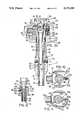
- FIG. 1is an elevational view of a surgical apparatus embodying the invention.
- FIG. 2is an enlarged, exploded view of the tool lock device of the apparatus of FIG. 1.
- FIGS. 3A, 3B and 3Care enlarged fragmentary central cross sectional views each taken on the line 3--3 of FIG. 1 and showing a sequence of positions of parts taken during installation of a tool in the sleeve and tool lock device from which the sleeve extends.
- FIG. 4is an enlarged fragmentary exploded view of a portion of a tool as it approaches the open lock plate of the tool lock device prior to locking.
- FIG. 5is an enlarged exploded view similar to FIG. 4 but with the lock plate in its closed position for locking together the tool and sleeve in their FIG. 1 use position.
- FIG. 6is an enlarged exploded view of the release pin and its spring of FIGS. 4 and 5.
- FIG. 7is an enlarged exploded view of the lock plate unit of FIGS. 4 and 5.
- FIG. 8is a fragmentary elevational view of the locking device of FIG. 1 and substantially taken on the line 8--8 of FIG. 1.
- FIG. 9is a sectional view substantially taken on the line 9--9 of FIG. 8.
- FIGS. 10 and 11are sectional views substantially taken on the line 10--10 of FIG. 3A and 11--11 of FIG. 3C, respectively.
- a surgical apparatus 10(FIG. 1), particularly usable in arthroscopic surgery, comprises a hollow, elongate sleeve 11 having a central passage 15.
- the sleeve 11includes an elongate hollow sleeve element 12 having a lower end 13 insertable into the tissue of a patient, namely into an inspection or surgical site (not shown) therein.
- the sleeve 11further includes a fitting 14 (FIG. 3C) fixed, as by press fit, over the top of the sleeve element 12.
- the fitting 14is hollow and continues the central passage 15 through the sleeve.
- Stopcocks 16 and 17extend radially and fixedly from the fitting 14, on opposite sides thereof, and are connectable to sources L and S respectively of irrigant liquid and suction, or to other suitable fluid connections.
- the stopcockscommunicate, as generally indicated at 18 (FIGS. 1 and 3C) with the central passage 15 of the sleeve 11.
- the stopcocksare equipped with valves 20 and 21 manually actuable to open and close communication between the central passage 15 and sources L and S, respectively, and thereby with the surgical site into which the lower end 13 of the sleeve 11 extends during surgery.
- the central passage 15continues upward coaxially through the sleeve 11 and its upper end portion widens upwardly to form a widened frustoconical mouth 22 to facilitate downward reception of a tool therethrough.
- the sleeve 11is intended to alternatively receive a variety of tools during the course of a surgical procedure.
- toolsinclude a trocar, an arthroscope or an obturator, among others.
- the tool 30 shown in FIGS. 1 and 3Cis a trocar.
- Each tool 30has an elongate shank 31 which is installed by inserting its patient engaging, bottom end 32 (FIG. 1) downward into the upward opening, frustoconical mouth 22 of the sleeve 11 and then allowing the tool shank 31 to slide downwardly through the central passage 15 until its patient engaging bottom end 32 reaches substantially the lower end 13 of the sleeve 11 (in the embodiment shown, protruding down and slightly therebeyond).
- the shank 31fits within the central passage 15 of the shell 11 closely, but with enough clearance to permit fluid flow in the annular space between the shank 31 and the peripheral wall of the central passage 15.
- Such flowis axially between the stopcocks 16 and 17 and the lower end 13 of the sleeve 11, for example, to permit irrigant liquid from the source L to travel down the outside of the shank 31 to the surgical site or to allow suction by the source S of flowable materials from the wound site toward the suction source S.
- the passage 15 and shank 31are both substantially cylindrical.
- the tool 30Integral with the upper end portion of the shank 31, the tool 30 includes a downward tapering, frustoconical portion 33 (FIG. 3C) for seating snugly and sealingly in the frustoconical mouth 22 when the shank 31 is inserted fully into the sleeve 11.
- a lock device 40is provided atop the sleeve 11 and interacts between the sleeve 11 and tool 30.
- the surgical apparatus 10is substantially conventional.
- the tool 30includes a cylindrical portion 34 (FIGS. 1 and 3C). Spaced between the ends of the cylindrical portion 34 is an annular lock groove 35.
- the tool 30includes a radially enlarged head 36 extending upward integrally and coaxially from the cylindrical portion 34, in spaced relation above the annular lock groove 35.
- the head 36is shaped for convenient hand engagement by the user, particularly in inserting the tool 30 into the sleeve 15 and withdrawing same upwardly out of the sleeve.
- an upstanding, eccentrically located lug 41(FIG. 1) is engagable with a shallow notch 42 (FIG. 3C) in the bottom peripheral edge of the head 36.
- the sleeve 11includes an upward extension 50 (FIG. 3C) having a lower end portion sealingly fixed by set screws 51 in an upward opening bore 43 in the fitting 14.
- the extension 50(or taper housing) thus sealingly continues upward the central passage 15, and indeed, at its upper end, carries the frustoconical mouth 22. In the embodiment shown, it is the interior of the sleeve extension 50 which communicates at 18 with the stopcocks 16 and 17.
- the snug connection of the sleeve element 12 and sleeve extension 50 in coaxially communicating recesses in the fitting 14assures a continuous leak-proof liquid or gas communication between the fitting 14 and the lower end 13 of the sleeve element 12.
- the lock device 40 in the preferred embodiment of the inventionincludes a lock housing 52 (FIGS. 1 and 3C).
- the lock housing 52has upper, mid and lower parts respectively defining a substantially cylindrical body 53, a radial flange 54 and a depending tubular skirt 55.
- the lock housing 52has a central bore 56 in which is received the upward extension 50 of the sleeve 11.
- the lower end of the skirt 55is snugly but slidably received coaxially in an upward opening annular recess 57 (FIG. 3C) in the top of the fitting 14.
- a coil compression spring 60(FIGS. 3B and 3C) urges the lock housing 52 downward with respect to the sleeve 11, to bottom the skirt 55 in the annular recess 57 as seen in FIG. 3A.
- the spring 60is housed in an annular space 61 (FIG. 3B) defined axially between a downward facing radial step 62 in the upward extension 50 of the sleeve 11 and an upward facing radial step 63 in the central bore 56 of the lock housing 52.
- the annular space 61is located axially near the bottom of the body 53 and below the frustoconical mouth 22.
- the opposing steps 62 and 63have a radial width somewhat exceeding the radial extent of the spring 60 so that the spring 60 clears the proposed inner and outer cylindrical surfaces of the body 53 and sleeve extension 50 sufficient to enable free telescoping movement of the lock housing 52 on the sleeve extension 50.
- the spring 60resiliently bottoms the lower end of the skirt 55 in the annular recess 57 to prevent the lock housing 52 from escaping upwardly off the top of the sleeve 11, and for determining the lowermost position of the lock housing 52, on the upward sleeve extension 50, as shown in FIG. 3A.
- a radially outwardly facing, axially extending, axially blind groove 64 in the sleeve extension 50is vertically spaced between the spring annular space 61 and the frustoconical mouth 22.
- An anti-rotate pin 65(FIGS. 2 and 9) is inserted through a radial hole 66 in the body 53 of the lock housing 52 and enters the groove 64 to prevent relative rotation between the lock housing 52 and sleeve 11.
- a set screw 67is threaded into the outside portion of the hole 66 to prevent non-intended escape of the pin 65 from the groove 64.
- the top and bottom of the groove 64may be located to provide an additional or alternative set of limits of vertical displacement of the lock housing 52 on the sleeve 11.
- the central bore 56 of the lock housing 52forms a deep, somewhat enlarged diameter, recess 70 into which the somewhat enlarged diameter top portion 71 (FIGS. 2 and 3C) of the sleeve upward extension 50 is snugly but slidably received.
- An undercut groove 72(FIGS. 1, 2 and 9) extends diametrally across the top of the lock housing body 53.
- the open top 73 of the grooveis of lateral width slightly exceeding the diameter of the recess 70.
- the undercut groove 72opens at its opposite ends diametrally through the periphery of the lock housing body 53.
- the length edges 74 of the undercut portion of the undercut groove 72are spaced laterally apart a distance substantially exceeding the diameter of the recess 70, as can be seen from FIGS. 2, 10 and 11.
- a lock member 75(FIG. 7) comprises a lock plate 76 having a lock cup 77 at one end thereof.
- the lock plate 76is snugly but slidably received diametrally in the undercut groove 72 as indicated in FIGS. 1, 2, 3C and 8-11.
- the lock cup 77depends from one end (the left end in FIG. 3C) of the lock plate 76 in a rigid fashion, extends leftwardly beyond the lock plate 76 and opens rightwardly into the space under the lock plate and along the length direction of the lock plate. With the lock plate 76 extending along the undercut groove as shown in FIGS. 3C, 10 and 11, the cup 77 opens rightwardly toward a radially shallow recess 80 (FIGS. 2, 3C and 10) in the peripheral wall of the lock housing body 53.
- the recess 80is generally U-shaped in elevation as seen in FIG. 2 and is sized to laterally receive the lock cup 77 in at least partially recessed relation therein throughout the normal range of lateral movement of the lock plate 76 in the undercut groove 72.
- a lock spring 81here a coil spring of compression type, is compressed diametrally of the lock housing body 53, between the closed leftward end 82 of the lock cup 77 and the opposed upstanding wall of the recess 80, so as to continuously resiliently urge the lock plate 76 leftwardly in FIGS. 3C, 10 and 11, and thereby in the normal direction of withdrawal of the lock plate 76 from the undercut groove 72 during disassembly of the apparatus.
- the spring 81is prevented from sliding the lock member 75 leftwardly (FIG. 3C) off the lock housing 52, and indeed the lateral position of the lock plate 76 in the undercut groove 72 is determined, by a release unit 83.
- the release unit 83(FIGS. 3C, 4-6, 10 and 11) comprises a release pin 84 (FIGS. 4-6) comprising a cylindrical base 85 (FIG. 6) which defines the maximum diameter of the pin. Above the cylindrical base 85, the pin 84 has two successive upward facing steps 86 and 87 (FIG. 6) which are separated by medium width part 88 of substantially cylindrical configuration, topped by an upward tapering annular bevel 90.
- the release pin 84further comprises a cylindrical narrow width part 91 topped by an enlarged diameter head 92.
- the release pin 84is receivable for its entire length downward into an upward opening blind hole 93 (FIGS. 2 and 3C) in the lock device body 53.
- the blind hole 93opens upward through the bottom 94 of the undercut groove 72 adjacent the end thereof furthest from the recess 80.
- the blind hole 93is generally centered in the undercut groove 72 and is closely spaced from the recess 70.
- a coil compression spring 95is trapped axially between a downward opening recess 96 (FIG. 3C) in the bottom of the release pin 94 and the bottom of the blind hole 93 in the body 53.
- the spring 95is sized to continuously urge the release pin 84 upward out of the blind hole 93.
- the lock plate 76has a relatively large diameter hole 100 (FIG. 7) opening therethrough.
- the hole 100is laterally centered between the side edges of the lock plate 76 and is nearer to the lock cup 77 than to the opposite end of the lock plate.
- a notch 101communicates with the hole 100, is centered between the side edges of the lock plate, and extends from the hole 100 in a direction away from the cup 77.
- a notch extension 102(FIG. 7) communicates with and extends beyond the closed end of the notch 101 in a direction away from the cup 75. The notch extension 102 is centered between the side edges of the lock plate 76.
- the blind end of the notch extension 102is close to but spaced from the end of the lock plate 76 remote from the cup 77 (the right end in FIG. 7).
- the lateral widths of the hole 100, notch 101 and notch extension 102are, respectively, relatively wide, of medium width and of relatively narrow width.
- the hole 100is circular and of diameter a bit larger than the diameter of the cylindrical portion 34 of the tool 30 (FIG. 4), so as to allow insertion of the portions 31, 33, 34 and 35 of the tool downward therethrough, in the manner seen, for example, in FIG. 3C.
- the notch 101is of lateral width to permit snug but slidable reception therein of the medium width part 88 of the release pin, as shown in FIGS. 3A, 3B, 4 and 10.
- the notch extension 102is of width sufficient to snugly but slidably receive the narrow width portion 91 of the release pin 84 as seen, for example, in FIGS. 3C, 5 and 11.
- the notch extension 102is too narrow to receive the medium width portion 88 or head 92 of the release pin 84.
- the apparatus 10(FIGS. 2 and 3C) can be assembled as follows.
- the top of the sleeve element 12is fixed, as by a press fit or an adhesive or as desired, in the bottom of the fitting 14.
- the fitting 14receives the lock housing skirt 55 downward into its annular recess 57 (FIG. 3C).
- the relaxed spring 60is dropped into the upfacing recess 70 in the body 53, to rest on the upward facing step 63 (FIG. 3B).
- the sleeve upward extension 50with its top portion 71 upward, is then dropped into the recess 70 of body 53 and its step 62 comes to rest upon the top of the spring 60.
- Set screws 51affix the sleeve upward extension 50 within the fitting 14.
- the skirt 55preferably has a downward facing step 103 (FIGS. 2 and 3C) which seats upon the bottom of the annular recess 57 in the fitting 14.
- the pin 65 and set screw 67(FIG. 9) are installed in the body 53 with the pin 65 slidably lodged in the groove 64 in the sleeve extension 50, so as to prevent rotation of the sleeve extension 50 within the lock housing body 53.
- the release pin spring 95 and release pin 84are successively dropped into the blind hole 93 (FIG. 3C) in the top of the body 53.
- the lock plate 76with the spring 81 captive in the cup 77, is slid (rightwardly in FIG. 3C) into the undercut groove 72 in the body 53.
- the release pin 84is manually held down with its head 92 below the bottom 94 of the undercut groove 72, thereby allowing the lock plate to slide rightwardly (FIG. 3C) over the top of the release pin 84.
- Continued rightward sliding of the lock plate 76brings the notch extension 102 and then the notch 101 over the top of the release pin 84.
- the release pinWhen the notch 101 is over the top of the release pin, the release pin is allowed to rise into the notch 101 until its lower step 86 hits the bottom of the lock plate 76, as in FIGS. 3A, 3B, 4 and 10. In this position, the release pin 84 prevents leftward (FIG. 3C) escape of the lock member 75 from atop the body 53, and the bottom of the lock plate 76 bears upon the lower step 86 of the release pin 84 to prevent upward escape of the release pin from the body 53.
- a tool 30can be installed therein as follows.
- the lock member 75Prior to inserting the tool 30, the lock member 75 is shifted to its open position (with its hole 100 coaxial with the sleeve 11), shown in FIGS. 3A and 10. Then, the bottom end 32 (FIG. 1) of the tool 30 is dropped into the frustoconical mouth 22 of the sleeve central passage 15, until the bottom of the head 36 of the tool 30 comes to rest upon the upward protruding lug 41 (FIGS. 2 and 9).
- the open lock member 75permits tool shank 31 and frustoconical portion 33 and the lower cylindrical portion 34 (FIG. 4) to pass downward through the lock plate hole 100.
- the tool head 36is then rotated sufficient to bring one of the notches 42 into position above the lug 41 (as in FIG.
- the tool 30is locked into the lock device 40 and sleeve 11 as follows. With one of the notches 42 receiving the lug 41, the head 36 of the tool 30 can be palmed by the user and the first two fingers of the user's same hand can straddle the skirt 55 and then pull up on the underside of the radial flange 54 of the lock housing 52 to raise the lock housing 52 from its FIG. 3A position to its FIG. 3B position to its FIG. 3C position on the sleeve 11. This compresses the spring 60 and causes the bottom of the tool head 36 to depress the release pin 84 sufficient to drop its medium width portion 88 and bevel 90 below the lock plate 76 (see the transition from FIG. 3B to FIG. 3C and from FIG. 4 to FIG. 5).
- the spring 81is free to displace the lock plate 76 leftward from its FIG. 3B and 10 open position to its FIG. 3C and 11 closed position. This brings the ear-like edges 104 (FIG. 11) of the lock plate 76, where the hole 100 meets the notch 101, into the annular groove 35 in the tool 30, as shown in FIGS. 3C and 11, and thereby prevents the tool 30 from being pulled upward out of the lock housing 52 and sleeve 11.
- the lock member 40is then be released and the spring 60 will push same downward on the sleeve upward extension 50, enough to resiliently urge the lock plate 76 firmly down upon the bottom of the annular groove 35 in the tool 30.
- the tool 30is thus axially and circumferentially locked within the lock device 40 and sleeve 11. This places the apparatus 10 in condition for surgical use.
Landscapes
- Health & Medical Sciences (AREA)
- Surgery (AREA)
- Life Sciences & Earth Sciences (AREA)
- Biomedical Technology (AREA)
- Nuclear Medicine, Radiotherapy & Molecular Imaging (AREA)
- Engineering & Computer Science (AREA)
- Pathology (AREA)
- Heart & Thoracic Surgery (AREA)
- Medical Informatics (AREA)
- Molecular Biology (AREA)
- Animal Behavior & Ethology (AREA)
- General Health & Medical Sciences (AREA)
- Public Health (AREA)
- Veterinary Medicine (AREA)
- Surgical Instruments (AREA)
Abstract
Description
Claims (14)
Priority Applications (1)
| Application Number | Priority Date | Filing Date | Title |
|---|---|---|---|
| US07/589,418US5171245A (en) | 1990-09-27 | 1990-09-27 | Surgical apparatus including a spring activated locking device |
Applications Claiming Priority (1)
| Application Number | Priority Date | Filing Date | Title |
|---|---|---|---|
| US07/589,418US5171245A (en) | 1990-09-27 | 1990-09-27 | Surgical apparatus including a spring activated locking device |
Publications (1)
| Publication Number | Publication Date |
|---|---|
| US5171245Atrue US5171245A (en) | 1992-12-15 |
Family
ID=24357934
Family Applications (1)
| Application Number | Title | Priority Date | Filing Date |
|---|---|---|---|
| US07/589,418Expired - LifetimeUS5171245A (en) | 1990-09-27 | 1990-09-27 | Surgical apparatus including a spring activated locking device |
Country Status (1)
| Country | Link |
|---|---|
| US (1) | US5171245A (en) |
Cited By (37)
| Publication number | Priority date | Publication date | Assignee | Title |
|---|---|---|---|---|
| US5308350A (en)* | 1990-04-11 | 1994-05-03 | Mikhail Michael W E | Femoral distractor for use in knee surgery |
| US5342363A (en)* | 1992-11-30 | 1994-08-30 | Wright Medical Technology, Inc. | Medical instrument and procedure |
| EP0648470A1 (en)* | 1993-10-08 | 1995-04-19 | United States Surgical Corporation | Surgical instrument positioning device |
| US5456673A (en)* | 1994-03-23 | 1995-10-10 | Stryker Corporation | Locking cannula for endoscopic surgery |
| US5602449A (en)* | 1992-04-13 | 1997-02-11 | Smith & Nephew Endoscopy, Inc. | Motor controlled surgical system and method having positional control |
| USD381425S (en)* | 1995-10-31 | 1997-07-22 | Smith & Nephew Endoscopy Inc. | Hub for a surgical instrument |
| US5672945A (en)* | 1992-04-13 | 1997-09-30 | Smith & Nephew Endoscopy, Inc. | Motor controlled surgical system and method having self clearing motor control |
| US5707363A (en)* | 1996-02-29 | 1998-01-13 | Becton Dickinson And Company | Guidewire retention device |
| US5712543A (en)* | 1995-10-31 | 1998-01-27 | Smith & Nephew Endoscopy Inc. | Magnetic switching element for controlling a surgical device |
| USD390956S (en) | 1996-10-23 | 1998-02-17 | Smith & Nephew, Inc. | Hub for a surgical instrument |
| USD390955S (en) | 1996-10-23 | 1998-02-17 | Smith & Nephew, Inc. | Hub for a surgical instrument |
| EP0746358A4 (en)* | 1993-08-30 | 1998-12-16 | Surgin Surgical Instrumentatio | Safety device for laparoscopic instruments |
| US5871493A (en)* | 1995-10-31 | 1999-02-16 | Smith & Nephew Endoscopy Inc. | Surgical instrument handpiece and system |
| WO2001001871A1 (en)* | 1999-07-02 | 2001-01-11 | Smith & Nephew, Inc. | Cannula with coupling interface |
| US6245084B1 (en) | 1998-10-20 | 2001-06-12 | Promex, Inc. | System for controlling a motor driven surgical cutting instrument |
| EP1069924B1 (en)* | 1998-04-09 | 2004-02-04 | Becton, Dickinson and Company | Catheter and introducer needle assembly with needle shield |
| US20040064141A1 (en)* | 2001-02-10 | 2004-04-01 | Andre Lechot | Modular tool connection assembly |
| US20050192585A1 (en)* | 2004-02-27 | 2005-09-01 | Medtronic, Inc. | Surgical saw collet with closed drive ring |
| US20090088600A1 (en)* | 2007-09-27 | 2009-04-02 | Superdimension, Ltd. | Bronchoscope Adapter and Method |
| WO2009141099A1 (en)* | 2008-05-23 | 2009-11-26 | Alexander Reuter | Thoracic trocar |
| US20110202059A1 (en)* | 2006-11-17 | 2011-08-18 | Webb Lawrence X | External fixation assembly and method of use |
| US8663088B2 (en) | 2003-09-15 | 2014-03-04 | Covidien Lp | System of accessories for use with bronchoscopes |
| US8764725B2 (en) | 2004-02-09 | 2014-07-01 | Covidien Lp | Directional anchoring mechanism, method and applications thereof |
| US20140277056A1 (en)* | 2013-01-16 | 2014-09-18 | Pacesetter, Inc. | Medical device and method for accessing space along an interior surface of an anatomic layer |
| CN104068922A (en)* | 2014-06-27 | 2014-10-01 | 浙江天松医疗器械股份有限公司 | Protective puncture needle |
| US8870749B2 (en) | 2011-09-02 | 2014-10-28 | Stryker Corporation | Arrangement for minimal access surgery |
| US20140336634A1 (en)* | 2013-05-13 | 2014-11-13 | New Wave Surgical Corp. | Multifunctional attachment for electrocautery surgical device |
| US9055881B2 (en) | 2004-04-26 | 2015-06-16 | Super Dimension Ltd. | System and method for image-based alignment of an endoscope |
| US9131832B2 (en) | 2012-08-15 | 2015-09-15 | Stryker Corporation | Cannula arrangement for minimally invasive surgery |
| DE102014205080A1 (en)* | 2014-03-19 | 2015-09-24 | Richard Wolf Gmbh | Medical instrument |
| US20160206181A1 (en)* | 2013-10-02 | 2016-07-21 | Olympus Winter & Ibe Gmbh | Endoscope shaft |
| CN109771004A (en)* | 2019-01-15 | 2019-05-21 | 朱晓峰 | A pleural effusion drainage and puncture device for thoracic surgery |
| WO2019183491A1 (en)* | 2018-03-22 | 2019-09-26 | Dignity Health | Apparatus and bone cutting device for removal of bone tissue |
| US10582834B2 (en) | 2010-06-15 | 2020-03-10 | Covidien Lp | Locatable expandable working channel and method |
| US10952593B2 (en) | 2014-06-10 | 2021-03-23 | Covidien Lp | Bronchoscope adapter |
| US11219743B2 (en)* | 2018-02-20 | 2022-01-11 | Boston Scientific Scimed, Inc. | Puncture devices, and systems and methods for accessing tissue |
| US11464400B2 (en)* | 2014-09-29 | 2022-10-11 | Cook Medical Technologies Llc | Endoscope mountable visualization device quick-connect/release handle attachment mechanism |
Citations (4)
| Publication number | Priority date | Publication date | Assignee | Title |
|---|---|---|---|---|
| US4586496A (en)* | 1984-03-05 | 1986-05-06 | Waldemar Link Gmbh & Co. | Surgical chisel |
| US4589414A (en)* | 1983-04-27 | 1986-05-20 | Olympus Optical Co., Ltd. | Surgical cutting instrument |
| US4697586A (en)* | 1986-06-24 | 1987-10-06 | Gazale William J | Combined chisel-guide surgical instrument |
| US4798213A (en)* | 1987-09-09 | 1989-01-17 | Doppelt Samuel H | Bone biopsy apparatus |
- 1990
- 1990-09-27USUS07/589,418patent/US5171245A/ennot_activeExpired - Lifetime
Patent Citations (4)
| Publication number | Priority date | Publication date | Assignee | Title |
|---|---|---|---|---|
| US4589414A (en)* | 1983-04-27 | 1986-05-20 | Olympus Optical Co., Ltd. | Surgical cutting instrument |
| US4586496A (en)* | 1984-03-05 | 1986-05-06 | Waldemar Link Gmbh & Co. | Surgical chisel |
| US4697586A (en)* | 1986-06-24 | 1987-10-06 | Gazale William J | Combined chisel-guide surgical instrument |
| US4798213A (en)* | 1987-09-09 | 1989-01-17 | Doppelt Samuel H | Bone biopsy apparatus |
Non-Patent Citations (7)
| Title |
|---|
| FIGS. 1 and 2, partially broken and central cross sectional view (1 sheet).* |
| FIGS. 1 and 2, partially broken and central cross-sectional view (1 sheet). |
| FIGS. 3 and 4, side elevational and central cross sectional view (1 sheet).* |
| FIGS. 3 and 4, side elevational and central cross-sectional view (1 sheet). |
| Sketch 1, pictorial view of a tool (1 sheet).* |
| Sketches 2 and 3, aligned and non aligned flange (1 sheet).* |
| Sketches 2 and 3, aligned and non-aligned flange (1 sheet). |
Cited By (62)
| Publication number | Priority date | Publication date | Assignee | Title |
|---|---|---|---|---|
| US5308350A (en)* | 1990-04-11 | 1994-05-03 | Mikhail Michael W E | Femoral distractor for use in knee surgery |
| US5602449A (en)* | 1992-04-13 | 1997-02-11 | Smith & Nephew Endoscopy, Inc. | Motor controlled surgical system and method having positional control |
| US5672945A (en)* | 1992-04-13 | 1997-09-30 | Smith & Nephew Endoscopy, Inc. | Motor controlled surgical system and method having self clearing motor control |
| US5342363A (en)* | 1992-11-30 | 1994-08-30 | Wright Medical Technology, Inc. | Medical instrument and procedure |
| EP0746358A4 (en)* | 1993-08-30 | 1998-12-16 | Surgin Surgical Instrumentatio | Safety device for laparoscopic instruments |
| EP0648470A1 (en)* | 1993-10-08 | 1995-04-19 | United States Surgical Corporation | Surgical instrument positioning device |
| US5437645A (en)* | 1993-10-08 | 1995-08-01 | United States Surgical Corporation | Surgical instrument positioning device |
| US5456673A (en)* | 1994-03-23 | 1995-10-10 | Stryker Corporation | Locking cannula for endoscopic surgery |
| USD381425S (en)* | 1995-10-31 | 1997-07-22 | Smith & Nephew Endoscopy Inc. | Hub for a surgical instrument |
| US6328752B1 (en) | 1995-10-31 | 2001-12-11 | Smith & Nephew, Inc. | Method for positioning a surgical instrument relative to a surgical handpiece |
| US5712543A (en)* | 1995-10-31 | 1998-01-27 | Smith & Nephew Endoscopy Inc. | Magnetic switching element for controlling a surgical device |
| US6090122A (en)* | 1995-10-31 | 2000-07-18 | Smith & Nephew, Inc. | Surgical instrument handpiece and system |
| US5871493A (en)* | 1995-10-31 | 1999-02-16 | Smith & Nephew Endoscopy Inc. | Surgical instrument handpiece and system |
| US5707363A (en)* | 1996-02-29 | 1998-01-13 | Becton Dickinson And Company | Guidewire retention device |
| USD390955S (en) | 1996-10-23 | 1998-02-17 | Smith & Nephew, Inc. | Hub for a surgical instrument |
| USD390956S (en) | 1996-10-23 | 1998-02-17 | Smith & Nephew, Inc. | Hub for a surgical instrument |
| EP1069924B1 (en)* | 1998-04-09 | 2004-02-04 | Becton, Dickinson and Company | Catheter and introducer needle assembly with needle shield |
| US6245084B1 (en) | 1998-10-20 | 2001-06-12 | Promex, Inc. | System for controlling a motor driven surgical cutting instrument |
| US6358263B2 (en) | 1998-10-20 | 2002-03-19 | Promex, Inc. | System for controlling a motor driven surgical cutting instrument |
| US6450992B1 (en)* | 1999-07-02 | 2002-09-17 | Smith & Nephew, Inc. | Cannula interface |
| WO2001001871A1 (en)* | 1999-07-02 | 2001-01-11 | Smith & Nephew, Inc. | Cannula with coupling interface |
| US6695816B2 (en) | 1999-07-02 | 2004-02-24 | Smith & Nephew, Inc. | Cannula interface |
| US20040064141A1 (en)* | 2001-02-10 | 2004-04-01 | Andre Lechot | Modular tool connection assembly |
| US7150751B2 (en)* | 2001-02-10 | 2006-12-19 | Precimed S.A. | Modular tool connection assembly |
| US10383509B2 (en) | 2003-09-15 | 2019-08-20 | Covidien Lp | System of accessories for use with bronchoscopes |
| US9089261B2 (en) | 2003-09-15 | 2015-07-28 | Covidien Lp | System of accessories for use with bronchoscopes |
| US8663088B2 (en) | 2003-09-15 | 2014-03-04 | Covidien Lp | System of accessories for use with bronchoscopes |
| US8764725B2 (en) | 2004-02-09 | 2014-07-01 | Covidien Lp | Directional anchoring mechanism, method and applications thereof |
| US20050192585A1 (en)* | 2004-02-27 | 2005-09-01 | Medtronic, Inc. | Surgical saw collet with closed drive ring |
| US9055881B2 (en) | 2004-04-26 | 2015-06-16 | Super Dimension Ltd. | System and method for image-based alignment of an endoscope |
| US10321803B2 (en) | 2004-04-26 | 2019-06-18 | Covidien Lp | System and method for image-based alignment of an endoscope |
| US9050136B2 (en) | 2006-11-17 | 2015-06-09 | Wake Forest University Health Sciences | External fixation assembly and method of use |
| US8454603B2 (en)* | 2006-11-17 | 2013-06-04 | Wake Forest University Health Sciences | External fixation assembly and method of use |
| US20110202059A1 (en)* | 2006-11-17 | 2011-08-18 | Webb Lawrence X | External fixation assembly and method of use |
| US10390686B2 (en) | 2007-09-27 | 2019-08-27 | Covidien Lp | Bronchoscope adapter and method |
| US8905920B2 (en)* | 2007-09-27 | 2014-12-09 | Covidien Lp | Bronchoscope adapter and method |
| US10980400B2 (en) | 2007-09-27 | 2021-04-20 | Covidien Lp | Bronchoscope adapter and method |
| US20090088600A1 (en)* | 2007-09-27 | 2009-04-02 | Superdimension, Ltd. | Bronchoscope Adapter and Method |
| US9986895B2 (en) | 2007-09-27 | 2018-06-05 | Covidien Lp | Bronchoscope adapter and method |
| US9668639B2 (en) | 2007-09-27 | 2017-06-06 | Covidien Lp | Bronchoscope adapter and method |
| WO2009141099A1 (en)* | 2008-05-23 | 2009-11-26 | Alexander Reuter | Thoracic trocar |
| US10582834B2 (en) | 2010-06-15 | 2020-03-10 | Covidien Lp | Locatable expandable working channel and method |
| US8870749B2 (en) | 2011-09-02 | 2014-10-28 | Stryker Corporation | Arrangement for minimal access surgery |
| US9131832B2 (en) | 2012-08-15 | 2015-09-15 | Stryker Corporation | Cannula arrangement for minimally invasive surgery |
| US20160228139A1 (en)* | 2013-01-16 | 2016-08-11 | Pacesetter, Inc. | Medical device and method for accessing space along an interior surface of an anatomic layer |
| US20140277056A1 (en)* | 2013-01-16 | 2014-09-18 | Pacesetter, Inc. | Medical device and method for accessing space along an interior surface of an anatomic layer |
| US9339292B2 (en)* | 2013-01-16 | 2016-05-17 | Pacesetter, Inc. | Medical device for accessing space along an interior surface of an anatomic layer |
| US20140336634A1 (en)* | 2013-05-13 | 2014-11-13 | New Wave Surgical Corp. | Multifunctional attachment for electrocautery surgical device |
| US20160206181A1 (en)* | 2013-10-02 | 2016-07-21 | Olympus Winter & Ibe Gmbh | Endoscope shaft |
| DE102014205080B4 (en) | 2014-03-19 | 2023-07-13 | Richard Wolf Gmbh | medical instrument |
| US10080553B2 (en) | 2014-03-19 | 2018-09-25 | Richard Wolf Gmbh | Medical instrument |
| DE102014205080A1 (en)* | 2014-03-19 | 2015-09-24 | Richard Wolf Gmbh | Medical instrument |
| US10952593B2 (en) | 2014-06-10 | 2021-03-23 | Covidien Lp | Bronchoscope adapter |
| CN104068922A (en)* | 2014-06-27 | 2014-10-01 | 浙江天松医疗器械股份有限公司 | Protective puncture needle |
| CN104068922B (en)* | 2014-06-27 | 2016-07-06 | 浙江天松医疗器械股份有限公司 | Protection puncture needle |
| US11464400B2 (en)* | 2014-09-29 | 2022-10-11 | Cook Medical Technologies Llc | Endoscope mountable visualization device quick-connect/release handle attachment mechanism |
| US11219743B2 (en)* | 2018-02-20 | 2022-01-11 | Boston Scientific Scimed, Inc. | Puncture devices, and systems and methods for accessing tissue |
| US12090284B2 (en) | 2018-02-20 | 2024-09-17 | Bosto Scientific Scimed, Inc. | Puncture devices, and systems and methods for accessing tissue |
| WO2019183491A1 (en)* | 2018-03-22 | 2019-09-26 | Dignity Health | Apparatus and bone cutting device for removal of bone tissue |
| US11096698B2 (en) | 2018-03-22 | 2021-08-24 | Dignity Health | Apparatus and bone cutting device for removal of bone tissue |
| US12324596B2 (en) | 2018-03-22 | 2025-06-10 | Dignity Health | Apparatus and bone cutting device for removal of bone tissue |
| CN109771004A (en)* | 2019-01-15 | 2019-05-21 | 朱晓峰 | A pleural effusion drainage and puncture device for thoracic surgery |
Similar Documents
| Publication | Publication Date | Title |
|---|---|---|
| US5171245A (en) | Surgical apparatus including a spring activated locking device | |
| US5456673A (en) | Locking cannula for endoscopic surgery | |
| US5871471A (en) | Disposable value assembly for reusable surgical trocar | |
| EP0135364B1 (en) | Trocar assembly | |
| US5207681A (en) | Drill guide apparatus for perpendicular perforation of the cranium | |
| US5312363A (en) | Low friction slit valve | |
| US4944728A (en) | Intravenous catheter placement device | |
| US5405323A (en) | Catheter check valve assembly | |
| US5702369A (en) | Extendable device for enclosing cutting surfaces of surgical instruments | |
| US5496289A (en) | Surgical cannula system | |
| US6319266B1 (en) | Trocar system and method of use | |
| DE69325427T2 (en) | Adapter seal for laparoscopic cannula | |
| EP0542432B1 (en) | Trocar apparatus | |
| US5478329A (en) | Trocarless rotational entry cannula | |
| US5439455A (en) | Combination introducer cannula and reducer for use therein | |
| US9566052B2 (en) | Tissue retractor apparatus and methods | |
| US6228061B1 (en) | Trocar seal system having dual seals | |
| US4955906A (en) | Mammary prosthesis injector | |
| JPH0698146B2 (en) | Velez needle instrument | |
| JP2001508678A (en) | Catheter device provided with valved catheter receptacle and needle protector | |
| US5261895A (en) | Apparatus for guiding surgical instruments into a surgical site and blocking escape of fluids from the site | |
| MXPA05003555A (en) | Trocar system. | |
| EP1689302A2 (en) | Magnetic devices and apparatus for medical/surgical procedures and methods for using same | |
| MXPA05003675A (en) | Iv catheter introducer with retractable needle. | |
| WO2009068661A1 (en) | Device for thoracostomy |
Legal Events
| Date | Code | Title | Description |
|---|---|---|---|
| AS | Assignment | Owner name:STRYKER CORPORATION, MICHIGAN Free format text:ASSIGNMENT OF ASSIGNORS INTEREST.;ASSIGNOR:CEZANA, HAIM;REEL/FRAME:005466/0981 Effective date:19900926 | |
| STCF | Information on status: patent grant | Free format text:PATENTED CASE | |
| CC | Certificate of correction | ||
| FPAY | Fee payment | Year of fee payment:4 | |
| AS | Assignment | Owner name:BANK OF AMERICA NATIONAL TRUST AND SAVINGS ASSOCIA Free format text:SECURITY INTEREST;ASSIGNORS:STRYKER CORPORATION;STRYKER FAR EAST, INC.;STRYKER INTERNATIONAL INC.;AND OTHERS;REEL/FRAME:009817/0001 Effective date:19981204 Owner name:BANK OF AMERICA NATIONAL TRUST AND SAVINGS ASSOCIA Free format text:SECURITY AGREEMENT;ASSIGNORS:STRYKER CORPORATION;STRYKER FAR EAST, INC.;REEL/FRAME:014137/0212 Effective date:19981204 | |
| FEPP | Fee payment procedure | Free format text:PAYOR NUMBER ASSIGNED (ORIGINAL EVENT CODE: ASPN); ENTITY STATUS OF PATENT OWNER: LARGE ENTITY | |
| REFU | Refund | Free format text:REFUND - PAYMENT OF MAINTENANCE FEE, 4TH YEAR, LARGE ENTITY (ORIGINAL EVENT CODE: R183); ENTITY STATUS OF PATENT OWNER: LARGE ENTITY | |
| FPAY | Fee payment | Year of fee payment:8 | |
| AS | Assignment | Owner name:STRYKER CORPORATION, MICHIGAN Free format text:RELEASE OF SECURITY INTEREST;ASSIGNOR:BANK OF AMERICA, N.A. (F/K/A BANK OF AMERICA NATIONAL TRUST AND SAVINGS ASSOCIATION);REEL/FRAME:012539/0557 Effective date:20020124 Owner name:STRYKER FAR EAST, INC., MICHIGAN Free format text:RELEASE OF SECURITY INTEREST;ASSIGNOR:BANK OF AMERICA, N.A. (F/K/A BANK OF AMERICA NATIONAL TRUST AND SAVINGS ASSOCIATION);REEL/FRAME:012539/0557 Effective date:20020124 Owner name:STRYKER INTERNATIONAL, INC., MICHIGAN Free format text:RELEASE OF SECURITY INTEREST;ASSIGNOR:BANK OF AMERICA, N.A. (F/K/A BANK OF AMERICA NATIONAL TRUST AND SAVINGS ASSOCIATION);REEL/FRAME:012539/0557 Effective date:20020124 Owner name:HOWMEDICA OSTEONICS CORPORATION, MICHIGAN Free format text:RELEASE OF SECURITY INTEREST;ASSIGNOR:BANK OF AMERICA, N.A. (F/K/A BANK OF AMERICA NATIONAL TRUST AND SAVINGS ASSOCIATION);REEL/FRAME:012539/0557 Effective date:20020124 Owner name:PHYSIOTHERAPY ASSOCIATES, INC., MICHIGAN Free format text:RELEASE OF SECURITY INTEREST;ASSIGNOR:BANK OF AMERICA, N.A. (F/K/A BANK OF AMERICA NATIONAL TRUST AND SAVINGS ASSOCIATION);REEL/FRAME:012539/0557 Effective date:20020124 Owner name:STRYKER PUERTO RICO INC., MICHIGAN Free format text:RELEASE OF SECURITY INTEREST;ASSIGNOR:BANK OF AMERICA, N.A. (F/K/A BANK OF AMERICA NATIONAL TRUST AND SAVINGS ASSOCIATION);REEL/FRAME:012539/0557 Effective date:20020124 Owner name:STRYKER SALES CORPORATION, MICHIGAN Free format text:RELEASE OF SECURITY INTEREST;ASSIGNOR:BANK OF AMERICA, N.A. (F/K/A BANK OF AMERICA NATIONAL TRUST AND SAVINGS ASSOCIATION);REEL/FRAME:012539/0557 Effective date:20020124 Owner name:STRYKER TECHNOLOGIES CORPORATION, MICHIGAN Free format text:RELEASE OF SECURITY INTEREST;ASSIGNOR:BANK OF AMERICA, N.A. (F/K/A BANK OF AMERICA NATIONAL TRUST AND SAVINGS ASSOCIATION);REEL/FRAME:012539/0557 Effective date:20020124 Owner name:STRYKER FOREIGN HOLDCO, INC., MICHIGAN Free format text:RELEASE OF SECURITY INTEREST;ASSIGNOR:BANK OF AMERICA, N.A. (F/K/A BANK OF AMERICA NATIONAL TRUST AND SAVINGS ASSOCIATION);REEL/FRAME:012539/0557 Effective date:20020124 Owner name:SMD CORPORATION, MICHIGAN Free format text:RELEASE OF SECURITY INTEREST;ASSIGNOR:BANK OF AMERICA, N.A. (F/K/A BANK OF AMERICA NATIONAL TRUST AND SAVINGS ASSOCIATION);REEL/FRAME:012539/0557 Effective date:20020124 Owner name:HOWMEDICAL LEIBINGER, INC., MICHIGAN Free format text:RELEASE OF SECURITY INTEREST;ASSIGNOR:BANK OF AMERICA, N.A. (F/K/A BANK OF AMERICA NATIONAL TRUST AND SAVINGS ASSOCIATION);REEL/FRAME:012539/0557 Effective date:20020124 | |
| FPAY | Fee payment | Year of fee payment:12 |