US5171230A - Fast flush catheter valve - Google Patents
Fast flush catheter valveDownload PDFInfo
- Publication number
- US5171230A US5171230AUS07/800,126US80012691AUS5171230AUS 5171230 AUS5171230 AUS 5171230AUS 80012691 AUS80012691 AUS 80012691AUS 5171230 AUS5171230 AUS 5171230A
- Authority
- US
- United States
- Prior art keywords
- valve
- bore
- tube
- longitudinal bore
- actuating member
- Prior art date
- Legal status (The legal status is an assumption and is not a legal conclusion. Google has not performed a legal analysis and makes no representation as to the accuracy of the status listed.)
- Expired - Lifetime
Links
- 239000012530fluidSubstances0.000claimsabstractdescription26
- 230000000903blocking effectEffects0.000claimsabstractdescription6
- 238000004519manufacturing processMethods0.000claimsdescription4
- 238000000034methodMethods0.000claims3
- 238000000465mouldingMethods0.000claims1
- 230000000881depressing effectEffects0.000abstract1
- FAPWRFPIFSIZLT-UHFFFAOYSA-MSodium chlorideChemical compound[Na+].[Cl-]FAPWRFPIFSIZLT-UHFFFAOYSA-M0.000description9
- 239000008280bloodSubstances0.000description8
- 210000004369bloodAnatomy0.000description8
- 239000000463materialSubstances0.000description6
- 206010053567CoagulopathiesDiseases0.000description4
- 230000035602clottingEffects0.000description4
- 230000036772blood pressureEffects0.000description3
- 238000003780insertionMethods0.000description3
- 230000037431insertionEffects0.000description3
- 238000012986modificationMethods0.000description3
- 230000004048modificationEffects0.000description3
- 238000004891communicationMethods0.000description2
- 238000011010flushing procedureMethods0.000description2
- 238000010276constructionMethods0.000description1
- 239000002872contrast mediaSubstances0.000description1
- 230000000994depressogenic effectEffects0.000description1
- 230000003467diminishing effectEffects0.000description1
- 239000003814drugSubstances0.000description1
- 229940079593drugDrugs0.000description1
- 230000006870functionEffects0.000description1
- 239000012535impuritySubstances0.000description1
- 238000002347injectionMethods0.000description1
- 239000007924injectionSubstances0.000description1
- 239000004816latexSubstances0.000description1
- 229920000126latexPolymers0.000description1
- 239000007788liquidSubstances0.000description1
- 239000002991molded plasticSubstances0.000description1
- 229920001296polysiloxanePolymers0.000description1
- 238000010926purgeMethods0.000description1
- 239000012858resilient materialSubstances0.000description1
- 230000000630rising effectEffects0.000description1
- 239000011780sodium chlorideSubstances0.000description1
- 238000011144upstream manufacturingMethods0.000description1
Images

Classifications
- A—HUMAN NECESSITIES
- A61—MEDICAL OR VETERINARY SCIENCE; HYGIENE
- A61M—DEVICES FOR INTRODUCING MEDIA INTO, OR ONTO, THE BODY; DEVICES FOR TRANSDUCING BODY MEDIA OR FOR TAKING MEDIA FROM THE BODY; DEVICES FOR PRODUCING OR ENDING SLEEP OR STUPOR
- A61M39/00—Tubes, tube connectors, tube couplings, valves, access sites or the like, specially adapted for medical use
- A61M39/22—Valves or arrangement of valves
- A61M39/225—Flush valves, i.e. bypass valves for flushing line
Definitions
- This inventionrelates generally to valves used in medical applications, and more particularly, to valves having both drip and flush flow rates.
- Fast flush valvesare used in catheter systems in which the blood pressure of a patient is monitored.
- a typical catheter systemincludes a saline solution source that is connected by tubing to an inlet of a fast flush valve and an outlet of the valve is connected to a pressure transducer. Downstream of the pressure transducer, a three way stopcock is typically connected by tubing between the pressure transducer and a catheter that is inserted in the patient. This catheter system permits the flow of saline solution from the source through the valve, transducer, and stopcock to the catheter and then the patient.
- a capillary mounted within the fast flush valvereduces the saline solution flow to a drip rate that prevents the blood of the patient at the catheter insertion site from clotting.
- the saline solution in the tubing connecting the pressure transducer to the catheterremains in fluid communication with the blood of the patient.
- the fluid communication between the saline solution at the pressure transducer with the blood of the patientpermits the blood pressure of the patient to be monitored.
- the valveis actuated to provide a flush flow through the valve which clears the system out.
- the object of the present inventionis achieved in a flush valve easily constructed from a few simple components.
- the valve of the preferred embodiment of the inventionincludes a valve body having a longitudinal bore through the body for fluid flow.
- An elastomeric tubeis mounted through the valve body and transversely to the bore to normally block the flow of fluid through the longitudinal bore.
- a capillaryis inserted through the tube so that it is aligned with the longitudinal bore and transverse to the tube. The capillary provides a drip flow rate through the valve when the tube is in the normally fluid blocking position.
- An actuatoris mounted on the valve body and has an end that is proximate the tube. The other end of the actuator extends from the valve body and terminates in a button surface.
- the buttonmay be depressed to cause the other end of the actuator to deform the tube and thereby open the longitudinal bore to permit a flush flow through the bore of the valve.
- the actuatorfurther includes a pair of hinged wings that have plugs mounted along a surface of each wing. The wings are pivoted towards the valve body so the plugs may be inserted into the ends of the tube to secure the actuator to the valve body and to urge the tube outwardly into fluid tight engagement with the longitudinal bore.
- the valve of the present inventionis simple to assemble.
- the valve bodyis formed with the longitudinal bore, actuator bore, and valve core bore at right angles to each other.
- the tubeis press fitted into the valve core bore and an O-ring seal is inserted in a well surrounding the actuator bore.
- the O-ring sealis secured in the well by a snap-fit cap 10 and the actuator is placed in the actuator bore.
- a radial diaphragmextends from one end of the actuator to a collar which rests on the valve body.
- Two wings pivotably joined to the collarare rotated towards the valve to insert a plug extending from each wing into each end of the tubular valve core. Integral hooks formed on the outboard end of the wings engage grooves in the valve body to hold the wings and plugs in place.
- One advantage of the present inventionis a valve having relatively few components with relatively simple geometries.
- Another advantage of the present inventionis the use of relatively inexpensive materials to form the components of the valve.
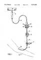
- FIG. 1is a perspective of a fast flush valve constructed in accordance with the principles of the present invention
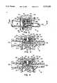
- FIG. 2is a cut-away view of the valve shown in FIG. 1;
- FIG. 3is a cross-sectional view of the valve in FIG. 2 taken along lines 3--3;
- FIG. 4is a cross-sectional view of the valve as shown in FIG. 3 showing the valve in a fast flush mode
- FIG. 5is an exploded view of the valve showing the assembly of the components to form the valve.
- FIG. 1shows a fast flush valve 10 constructed in accordance with the principles of the present invention in its most typical use.
- a fluid source 12such as a saline bottle or bag is connected via tubing 14 to flush valve 10.
- Tubing 14leads from valve 10 to a pressure transducer 16 which is used to measure the patient's blood pressure. Downstream of the transducer 16 is a stopcock 17 that may be used to withdraw blood samples or infuse medicines or contrast agents into the patient.
- Tubing 14leads from the stopcock 17 to a catheter 18 that is inserted into the arm 20 of a patient.
- valve 10performs two functions. The first is to permit a relatively high volume flow rate of fluid to clear air from the tubing and needle downstream of the valve prior to insertion into the patient's arm or to clear blood from the line to prevent clotting after a blood sample withdrawal through the stopcock. The second is the provision of a steady drip rate of the fluid from source 12 through valve 10 to keep blood from clotting at the needle in the patient's arm.
- the construction of the fast flush valve 10is shown in more detail in FIG. 2.
- the valve 10has a valve body 22 having an exterior surface 24 and an interior 26.
- a longitudinal bore 28connects an inlet 30 through the interior 26 of the valve body 22 to an outlet 32.
- a valve core bore 38Transversely oriented with respect to the bore 28 is a valve core bore 38 (best shown in FIG. 5).
- Press fitted within the valve core boreis an elastic tube 40 which blocks bore 28 from the outlet 32.
- a capillary 42extends through valve core 40 to provide a drip flow of fluid through the longitudinal bore 28 of valve 10.
- Valve core tube 40is preferably formed from a resilient, deformable material with an elastic memory.
- core 40is formed from SilasticTM tubes manufactured by Dow Corning Plastic Co. of Hemlock, Mich. and preferably has a rating of 35-50 on the Durometer scale.
- the valve coremay be made of latex or silicone having the same Durometer rating.
- Capillary 42is formed from deformable tubing such as PEEKTM tubing manufactured by The Munhill Company of Worthington, Ohio so that it is not destroyed by the deforming of the valve core 40.
- the capillaryis preferably a standard size tube with a 0.0025 inch inner diameter with a tolerance of ⁇ 0.0005 inch.
- Capillary 42preferably provides a drip flow rate of a nominal 3 cc per hour for an adult care system and 30 cc for a neonatal care system as is well known within the art.
- a pushbutton actuator 44that is mounted to the top of the valve body.
- the actuator 44includes a central actuating member 46 slidingly received in a vertical actuator member bore 48 in the body 22.
- the actuating member 46has an upper end 50 and a lower end 52.
- Radially extending from the upper end 50 to a collar 54is a biasing diaphragm 56.
- the collar 54rests on a ridge 55 on the body and has two diametrically opposed mounting wings 58 that are hinged to the collar 54 at joint 60 (best shown in FIG. 5).
- a plug 62extends from each of the wings 58 and the plug is pressed into the ends of the tube 40 to further expand the tube 40 into a fluid tight engagement with bore 38 and to secure actuator 44 to the valve body 22.
- hooks 61that seat within grooves 63 which are located on the valve body 22 below valve core bore 38.
- the securement of the hooks 61 within the grooves 63helps prevent the plugs 62 from being pushed out of the valve core 40.
- the tight fit of the actuator 44 to valve body 22helps ensure the liquid tightness of the valve 10.
- the actuator 44is made of a resilient material with elastic memory. This provides radial diaphragm 56 with sufficient flex to return actuator member 46 to the position in FIG. 3 when actuating member 46 is released from a vertically displaced position.
- Valve body 22is preferably formed from molded plastic with bore 28, valve core bore 38, and actuator member bore 48 formed therein, preferably at right angles to one another.
- O-ring seal 66is concentrically mounted about the actuating member 46 within seal cavity 70 to prevent fluids within longitudinal bore 28 from rising upwardly through vertical bore 48.
- Snap fitted into a circular groove 72 along the circumference of a well 73 in the valve body 22is a rounded flange 77 formed along the circumference of a cap 74. The fit of the flange 77 within the groove 72 further ensures the fluid integrity of the valve 10 and the secure attachment of the actuator 44 to the valve body 22.
- a relief area 33is provided in bore 28 on the inlet side of valve core 40.
- This relief areaprovides an area for back flow through the valve if an attendant injects material into the tubing 14 through stopcock 17 with the stopcock in a position which directs the material upstream.
- the pressure created from the injectionmay be sufficient to damage the pressure transducer 16 if the material is not allowed to pass back through the bore 28. Because the valve 10 permits this back flow, the transducer is not damaged and the attendant can correct the error by turning the stopcock 17 to the correct position and flushing the injected material from the tubing into the patient.
- valve 10In the operation of valve 10, the inlet 30 is connected to a fluid source 12 via tubing 14 as shown in FIG. 1. Outlet 32 is connected to transducer 16 via tubing 14 which is in turn connected by tubing 14 to the stopcock 17 as shown in FIG. 1 and thence to the catheter 18 which is inserted into the patient's arm. Prior to insertion, the actuator 44 is activated to provide a flush flow, described below, to push the air from the tubing 14 and to fill the tubing with saline solution. Once the catheter 18 is inserted and actuator 44 released, fluid from the source 12 enters into inlet 30 and is blocked in the longitudinal bore 28 by the valve core 40 (FIG. 3).
- the pressure difference between the fluid source and the patientpushes fluid at a drip rate through the capillary 42 extending through the valve core 40 to the outlet 32.
- This drip rate flow of saline solutionis transmitted through the stopcock and catheter to the bloodstream of the patient to keep the blood surrounding the catheter from clotting.
- FIG. 4Flushing the tubing 14 downstream of valve 10 is best shown in FIG. 4.
- the upper end 50 of actuating member 46When the upper end 50 of actuating member 46 is pushed downwardly, the lower end 52 of actuating member 46 is urged against the valve core 40 to deform the valve core. Fluid from the inlet 30 of the valve 10 flows through bore 28 by going around actuator member 46 and over the upper surface of the deformed valve core 40 to the outlet 32. This flow is larger in volume than the flow through capillary 42 and is sufficient to flush the tubing and catheter downstream of the valve 10. This flow continues as long as actuator member 46 is held in the position shown in FIG. 4.
- the radial flange 56Upon release, the radial flange 56 returns to the position shown in FIG. 3 which causes the actuator member 46 to withdraw within the vertical bore 48 so lower end 52 is proximate the valve core 40.
- the valve core 40also returns to the shape depicted in FIG. 3 to block bore 2 and terminate the flush flow. The drip flow continues through capillary 42.
- valve core 40is press fitted into the valve core bore 38 in valve body 22 to create a fluid tight seal around the valve core in longitudinal bore 28.
- Capillary 42is inserted through the open end of a hypodermic type needle and housed within the needle. The needle is inserted through the valve core 40 fitted in bore 38 that is blocking longitudinal bore 28 until the needle point extends through the valve core. Capillary 42 is pushed through the needle until it extends past the needle point and the needle is withdrawn from the valve core to permit the valve core 40 to close about the capillary 42.
- O-ring seal 66is dropped within cavity 70 and cap 74 is snap fitted into groove 72.
- the lower end 52 of actuator member 46is inserted through actuator member bore 48 until collar 54 comes to rest on ridge 55.
- Wings 58are pivoted about joint 60 to engage plugs 62 in the open ends of the valve core 40 and secure actuator 44 to valve body 22. Wings 58 are pushed until hooks 61 engage grooves 63 to hold the plugs 62 within the core 40.
Landscapes
- Health & Medical Sciences (AREA)
- Heart & Thoracic Surgery (AREA)
- Pulmonology (AREA)
- Engineering & Computer Science (AREA)
- Anesthesiology (AREA)
- Biomedical Technology (AREA)
- Hematology (AREA)
- Life Sciences & Earth Sciences (AREA)
- Animal Behavior & Ethology (AREA)
- General Health & Medical Sciences (AREA)
- Public Health (AREA)
- Veterinary Medicine (AREA)
- Infusion, Injection, And Reservoir Apparatuses (AREA)
Abstract
Description
Claims (10)
Priority Applications (5)
| Application Number | Priority Date | Filing Date | Title |
|---|---|---|---|
| US07/800,126US5171230A (en) | 1991-11-29 | 1991-11-29 | Fast flush catheter valve |
| PCT/US1992/010148WO1993010833A1 (en) | 1991-11-29 | 1992-11-25 | Fast flush catheter valve |
| CA002123896ACA2123896A1 (en) | 1991-11-29 | 1992-11-25 | Fast flush catheter valve |
| EP93900614AEP0614381A1 (en) | 1991-11-29 | 1992-11-25 | Fast flush catheter valve |
| AU32238/93AAU3223893A (en) | 1991-11-29 | 1992-11-25 | Fast flush catheter valve |
Applications Claiming Priority (1)
| Application Number | Priority Date | Filing Date | Title |
|---|---|---|---|
| US07/800,126US5171230A (en) | 1991-11-29 | 1991-11-29 | Fast flush catheter valve |
Publications (1)
| Publication Number | Publication Date |
|---|---|
| US5171230Atrue US5171230A (en) | 1992-12-15 |
Family
ID=25177552
Family Applications (1)
| Application Number | Title | Priority Date | Filing Date |
|---|---|---|---|
| US07/800,126Expired - LifetimeUS5171230A (en) | 1991-11-29 | 1991-11-29 | Fast flush catheter valve |
Country Status (5)
| Country | Link |
|---|---|
| US (1) | US5171230A (en) |
| EP (1) | EP0614381A1 (en) |
| AU (1) | AU3223893A (en) |
| CA (1) | CA2123896A1 (en) |
| WO (1) | WO1993010833A1 (en) |
Cited By (94)
| Publication number | Priority date | Publication date | Assignee | Title |
|---|---|---|---|---|
| US5360413A (en)* | 1991-12-06 | 1994-11-01 | Filtertek, Inc. | Needleless access device |
| US5725503A (en)* | 1996-08-07 | 1998-03-10 | Aeroquip Corporation | Ratcheting needle protector assembly |
| WO1998024495A1 (en) | 1996-12-02 | 1998-06-11 | Medex, Inc. | Two-part medical pressure transducer with diaphragm stand-offs |
| US5817069A (en)* | 1996-02-28 | 1998-10-06 | Vadus, Inc. | Valve assembly |
| US5820565A (en)* | 1996-11-04 | 1998-10-13 | Merit Medical System, Inc. | Flush valve with interlocking seal |
| US5823967A (en)* | 1996-11-04 | 1998-10-20 | Merit Medical Systems, Inc. | Flush valve with cable attachment |
| US5851196A (en)* | 1996-08-07 | 1998-12-22 | Vadus, Inc. | Needle protector |
| US5891110A (en)* | 1997-10-15 | 1999-04-06 | Scimed Life Systems, Inc. | Over-the-wire catheter with improved trackability |
| US5895376A (en)* | 1996-10-23 | 1999-04-20 | Mayo Foundation For Medical Education And Research | Hemostasis valve, system and assembly |
| US5954698A (en)* | 1997-01-08 | 1999-09-21 | Vadus, Inc. | Catheter apparatus having valved catheter hub and needle protector |
| US6048338A (en)* | 1997-10-15 | 2000-04-11 | Scimed Life Systems, Inc. | Catheter with spiral cut transition member |
| US6080137A (en)* | 1997-01-08 | 2000-06-27 | Vadus, Inc. | Needle protector |
| US6113579A (en)* | 1998-03-04 | 2000-09-05 | Scimed Life Systems, Inc. | Catheter tip designs and methods for improved stent crossing |
| US6264630B1 (en) | 1998-12-23 | 2001-07-24 | Scimed Life Systems, Inc. | Balloon catheter having an oscillating tip configuration |
| US6517515B1 (en) | 1998-03-04 | 2003-02-11 | Scimed Life Systems, Inc. | Catheter having variable size guide wire lumen |
| US6623504B2 (en) | 2000-12-08 | 2003-09-23 | Scimed Life Systems, Inc. | Balloon catheter with radiopaque distal tip |
| US6755391B2 (en) | 2000-10-23 | 2004-06-29 | Nypro Inc. | Anti-drawback medical valve |
| US20040172008A1 (en)* | 2002-11-19 | 2004-09-02 | Gmp/Cardiac Care, Inc. | Hemostasis valve and method of using a hemostasis valve |
| US6830563B1 (en) | 2001-08-24 | 2004-12-14 | Scott Singer | Syringe tip providing nonlaminar spiral flow and method of use for flushing catheters |
| US6869426B2 (en) | 2001-11-13 | 2005-03-22 | Nypro Inc. | Anti-drawback medical valve |
| US6883778B1 (en) | 1996-11-18 | 2005-04-26 | Nypro Inc. | Apparatus for reducing fluid drawback through a medical valve |
| US7172572B2 (en) | 2001-10-04 | 2007-02-06 | Boston Scientific Scimed, Inc. | Manifold system for a medical device |
| US7201763B2 (en) | 2001-10-24 | 2007-04-10 | Boston Scientific Scimed, Inc. | Distal balloon waist material relief and method of manufacture |
| US20070088313A1 (en)* | 1995-03-20 | 2007-04-19 | Medimop Medical Projects, Ltd. | Fluid transfer device |
| US7314462B2 (en) | 2005-04-12 | 2008-01-01 | Span-America Medical Systems, Inc. | Passive needle-stick protector |
| US20080009789A1 (en)* | 2004-04-29 | 2008-01-10 | Medimop Medical Projects Ltd. | Liquid Drug Medical Devices and Needle Shield Removal Device |
| US7357792B2 (en) | 2002-10-29 | 2008-04-15 | Nypro Inc. | Positive push medical valve with internal seal |
| US7396348B2 (en) | 2001-08-22 | 2008-07-08 | Nypro Inc. | Medical valve with expandable member |
| US20090082750A1 (en)* | 2006-03-16 | 2009-03-26 | Medimop Medical Projects Ltd. | Fluid transfer devices for use with cartridges |
| US20090177177A1 (en)* | 2005-08-11 | 2009-07-09 | Medimop Medical Projects Ltd. | Liquid Drug Transfer Devices for Failsafe Correct Snap Fitting Onto Medicinal Vials |
| US20090265000A1 (en)* | 2004-12-29 | 2009-10-22 | Jerome Vaudant | Small incision intraocular lens with anti-pco feature |
| US7744574B2 (en) | 2004-12-16 | 2010-06-29 | Boston Scientific Scimed, Inc. | Catheter tip to reduce wire lock |
| US20100168664A1 (en)* | 2007-04-17 | 2010-07-01 | Medimop Medical Projects Ltd. | Fluid control device with manually depressed actuator |
| US7753892B2 (en) | 2001-11-13 | 2010-07-13 | Nypro Inc. | Anti-drawback medical valve |
| US20100198148A1 (en)* | 2007-09-25 | 2010-08-05 | Medimop Medical Projects Ltd. | Liquid drug delivery devices for use with syringes with widened distal tips |
| US20100204679A1 (en)* | 2007-09-18 | 2010-08-12 | Medimop Medical Projects Ltd. | Medicament mixing and injection apparatus |
| US7789864B2 (en) | 1996-11-18 | 2010-09-07 | Nypro Inc. | Luer-activated valve |
| US20100234759A1 (en)* | 2006-06-14 | 2010-09-16 | William Wekell | Reusable Invasive Fluid Pressure Monitoring Apparatus and Method |
| US7815168B2 (en) | 2006-04-11 | 2010-10-19 | Nypro Inc. | Medical valve with rotating member and method |
| US7837658B2 (en) | 2001-11-13 | 2010-11-23 | Nypro Inc. | Anti-drawback medical valve |
| US7887519B2 (en) | 2005-01-14 | 2011-02-15 | Nypro Inc. | Valve with internal lifter |
| US7914502B2 (en) | 2003-07-31 | 2011-03-29 | Nypro Inc. | Anti-drawback medical valve |
| USD641080S1 (en)* | 2009-03-31 | 2011-07-05 | Medimop Medical Projects Ltd. | Medical device having syringe port with locking mechanism |
| US8100869B2 (en) | 2006-08-11 | 2012-01-24 | Nypro Inc. | Medical valve with expandable member |
| USD669980S1 (en) | 2010-10-15 | 2012-10-30 | Medimop Medical Projects Ltd. | Vented vial adapter |
| USD674088S1 (en) | 2012-02-13 | 2013-01-08 | Medimop Medical Projects Ltd. | Vial adapter |
| US8568371B2 (en) | 2009-06-22 | 2013-10-29 | Np Medical Inc. | Medical valve with improved back-pressure sealing |
| US8608723B2 (en) | 2009-11-12 | 2013-12-17 | Medimop Medical Projects Ltd. | Fluid transfer devices with sealing arrangement |
| US8684994B2 (en) | 2010-02-24 | 2014-04-01 | Medimop Medical Projects Ltd. | Fluid transfer assembly with venting arrangement |
| US8752598B2 (en) | 2011-04-17 | 2014-06-17 | Medimop Medical Projects Ltd. | Liquid drug transfer assembly |
| US8753325B2 (en) | 2010-02-24 | 2014-06-17 | Medimop Medical Projects, Ltd. | Liquid drug transfer device with vented vial adapter |
| US8852145B2 (en) | 2010-11-14 | 2014-10-07 | Medimop Medical Projects, Ltd. | Inline liquid drug medical device having rotary flow control member |
| US8905994B1 (en) | 2011-10-11 | 2014-12-09 | Medimop Medical Projects, Ltd. | Valve assembly for use with liquid container and drug vial |
| USD720451S1 (en) | 2012-02-13 | 2014-12-30 | Medimop Medical Projects Ltd. | Liquid drug transfer assembly |
| US8979792B2 (en) | 2009-11-12 | 2015-03-17 | Medimop Medical Projects Ltd. | Inline liquid drug medical devices with linear displaceable sliding flow control member |
| US8998875B2 (en) | 2009-10-01 | 2015-04-07 | Medimop Medical Projects Ltd. | Vial assemblage with vial and pre-attached fluid transfer device |
| USD734868S1 (en) | 2012-11-27 | 2015-07-21 | Medimop Medical Projects Ltd. | Drug vial adapter with downwardly depending stopper |
| USD737436S1 (en) | 2012-02-13 | 2015-08-25 | Medimop Medical Projects Ltd. | Liquid drug reconstitution assembly |
| US9138572B2 (en) | 2010-06-24 | 2015-09-22 | Np Medical Inc. | Medical valve with fluid volume alteration |
| US20150314074A1 (en)* | 2008-09-23 | 2015-11-05 | Becton, Dickinson And Company | Apparatus And Methods For Purging Catheter Systems |
| US9283324B2 (en) | 2012-04-05 | 2016-03-15 | Medimop Medical Projects, Ltd | Fluid transfer devices having cartridge port with cartridge ejection arrangement |
| US9339438B2 (en) | 2012-09-13 | 2016-05-17 | Medimop Medical Projects Ltd. | Telescopic female drug vial adapter |
| USD757933S1 (en) | 2014-09-11 | 2016-05-31 | Medimop Medical Projects Ltd. | Dual vial adapter assemblage |
| USD765837S1 (en) | 2013-08-07 | 2016-09-06 | Medimop Medical Projects Ltd. | Liquid transfer device with integral vial adapter |
| USD767124S1 (en) | 2013-08-07 | 2016-09-20 | Medimop Medical Projects Ltd. | Liquid transfer device with integral vial adapter |
| US9795536B2 (en) | 2012-08-26 | 2017-10-24 | Medimop Medical Projects, Ltd. | Liquid drug transfer devices employing manual rotation for dual flow communication step actuations |
| USD801522S1 (en) | 2015-11-09 | 2017-10-31 | Medimop Medical Projects Ltd. | Fluid transfer assembly |
| US9801786B2 (en) | 2013-04-14 | 2017-10-31 | Medimop Medical Projects Ltd. | Drug container closure for mounting on open-topped drug container to form drug reconstitution assemblage for use with needleless syringe |
| US9839580B2 (en) | 2012-08-26 | 2017-12-12 | Medimop Medical Projects, Ltd. | Liquid drug transfer devices |
| US9943463B2 (en) | 2013-05-10 | 2018-04-17 | West Pharma. Services IL, Ltd. | Medical devices including vial adapter with inline dry drug module |
| US20180110966A1 (en)* | 2016-10-24 | 2018-04-26 | St. Jude Medical, Cardiology Division, Inc. | Catheter insertion devices |
| US9956377B2 (en) | 2002-09-20 | 2018-05-01 | Angiodynamics, Inc. | Method and apparatus for intra-aortic substance delivery to a branch vessel |
| USD832430S1 (en) | 2016-11-15 | 2018-10-30 | West Pharma. Services IL, Ltd. | Dual vial adapter assemblage |
| US10279112B2 (en) | 2012-09-24 | 2019-05-07 | Angiodynamics, Inc. | Power injector device and method of use |
| US10278897B2 (en) | 2015-11-25 | 2019-05-07 | West Pharma. Services IL, Ltd. | Dual vial adapter assemblage including drug vial adapter with self-sealing access valve |
| US10285907B2 (en) | 2015-01-05 | 2019-05-14 | West Pharma. Services IL, Ltd. | Dual vial adapter assemblages with quick release drug vial adapter for ensuring correct usage |
| US10357429B2 (en) | 2015-07-16 | 2019-07-23 | West Pharma. Services IL, Ltd. | Liquid drug transfer devices for secure telescopic snap fit on injection vials |
| US10646404B2 (en) | 2016-05-24 | 2020-05-12 | West Pharma. Services IL, Ltd. | Dual vial adapter assemblages including identical twin vial adapters |
| US10688295B2 (en) | 2013-08-07 | 2020-06-23 | West Pharma. Services IL, Ltd. | Liquid transfer devices for use with infusion liquid containers |
| US10765604B2 (en) | 2016-05-24 | 2020-09-08 | West Pharma. Services IL, Ltd. | Drug vial adapter assemblages including vented drug vial adapter and vented liquid vial adapter |
| US10772797B2 (en) | 2016-12-06 | 2020-09-15 | West Pharma. Services IL, Ltd. | Liquid drug transfer devices for use with intact discrete injection vial release tool |
| US10806671B2 (en) | 2016-08-21 | 2020-10-20 | West Pharma. Services IL, Ltd. | Syringe assembly |
| US10806667B2 (en) | 2016-06-06 | 2020-10-20 | West Pharma. Services IL, Ltd. | Fluid transfer devices for filling drug pump cartridges with liquid drug contents |
| US10945921B2 (en) | 2017-03-29 | 2021-03-16 | West Pharma. Services IL, Ltd. | User actuated liquid drug transfer devices for use in ready-to-use (RTU) liquid drug transfer assemblages |
| USD917693S1 (en) | 2018-07-06 | 2021-04-27 | West Pharma. Services IL, Ltd. | Medication mixing apparatus |
| USD923782S1 (en) | 2019-01-17 | 2021-06-29 | West Pharma. Services IL, Ltd. | Medication mixing apparatus |
| USD923812S1 (en) | 2019-01-16 | 2021-06-29 | West Pharma. Services IL, Ltd. | Medication mixing apparatus |
| USD954253S1 (en) | 2019-04-30 | 2022-06-07 | West Pharma. Services IL, Ltd. | Liquid transfer device |
| US11369739B2 (en) | 2013-01-21 | 2022-06-28 | Medline Industries, Lp | Method to provide injection system parameters for injecting fluid into patient |
| USD956958S1 (en) | 2020-07-13 | 2022-07-05 | West Pharma. Services IL, Ltd. | Liquid transfer device |
| US11642285B2 (en) | 2017-09-29 | 2023-05-09 | West Pharma. Services IL, Ltd. | Dual vial adapter assemblages including twin vented female vial adapters |
| US11918542B2 (en) | 2019-01-31 | 2024-03-05 | West Pharma. Services IL, Ltd. | Liquid transfer device |
| US12274670B2 (en) | 2019-04-09 | 2025-04-15 | West Pharma. Services IL, Ltd. | Liquid transfer device with integrated syringe |
| US12427091B2 (en) | 2019-01-18 | 2025-09-30 | West Pharma. Services IL, Ltd. | Liquid transfer devices for use with intravenous (IV) bottles |
Citations (8)
| Publication number | Priority date | Publication date | Assignee | Title |
|---|---|---|---|---|
| US2934314A (en)* | 1957-01-18 | 1960-04-26 | Electro Way Corp | Valve |
| US4624662A (en)* | 1982-11-24 | 1986-11-25 | Transamerica Delaval Inc. | Catheter flushing systems |
| US4648868A (en)* | 1985-09-30 | 1987-03-10 | American Hospital Supply Corporation | Apparatus for controlling flow and pressure measurement |
| US4696305A (en)* | 1985-07-15 | 1987-09-29 | Peter von Berg Extrakorporale Systems-Medizintechnik GmbH | Flow controller |
| US4739770A (en)* | 1986-05-21 | 1988-04-26 | Hewlett-Packard Company | Flush device |
| GB2207736A (en)* | 1987-08-06 | 1989-02-08 | Concord Lab Inc | Control valve |
| US4934375A (en)* | 1988-03-04 | 1990-06-19 | Spectramed, Inc. | Flush-valve assembly for blood pressure measurement catheter |
| US4960259A (en)* | 1987-09-17 | 1990-10-02 | Joka Kathetertechnik Gmbh | Shut-off valve for a liquid flow line or infusion device |
Family Cites Families (3)
| Publication number | Priority date | Publication date | Assignee | Title |
|---|---|---|---|---|
| US4210178A (en)* | 1977-08-10 | 1980-07-01 | Basta Michael I | Perpetual by-pass flushing device |
| US4497468A (en)* | 1982-04-26 | 1985-02-05 | Graphic Controls Corporation | Catheter patency flush flow controller |
| DE3417257A1 (en)* | 1984-05-10 | 1985-11-14 | B. Braun Melsungen Ag, 3508 Melsungen | RINSING DEVICE FOR A CATHETER |
- 1991
- 1991-11-29USUS07/800,126patent/US5171230A/ennot_activeExpired - Lifetime
- 1992
- 1992-11-25WOPCT/US1992/010148patent/WO1993010833A1/ennot_activeApplication Discontinuation
- 1992-11-25CACA002123896Apatent/CA2123896A1/ennot_activeAbandoned
- 1992-11-25EPEP93900614Apatent/EP0614381A1/ennot_activeWithdrawn
- 1992-11-25AUAU32238/93Apatent/AU3223893A/ennot_activeAbandoned
Patent Citations (8)
| Publication number | Priority date | Publication date | Assignee | Title |
|---|---|---|---|---|
| US2934314A (en)* | 1957-01-18 | 1960-04-26 | Electro Way Corp | Valve |
| US4624662A (en)* | 1982-11-24 | 1986-11-25 | Transamerica Delaval Inc. | Catheter flushing systems |
| US4696305A (en)* | 1985-07-15 | 1987-09-29 | Peter von Berg Extrakorporale Systems-Medizintechnik GmbH | Flow controller |
| US4648868A (en)* | 1985-09-30 | 1987-03-10 | American Hospital Supply Corporation | Apparatus for controlling flow and pressure measurement |
| US4739770A (en)* | 1986-05-21 | 1988-04-26 | Hewlett-Packard Company | Flush device |
| GB2207736A (en)* | 1987-08-06 | 1989-02-08 | Concord Lab Inc | Control valve |
| US4960259A (en)* | 1987-09-17 | 1990-10-02 | Joka Kathetertechnik Gmbh | Shut-off valve for a liquid flow line or infusion device |
| US4934375A (en)* | 1988-03-04 | 1990-06-19 | Spectramed, Inc. | Flush-valve assembly for blood pressure measurement catheter |
Cited By (132)
| Publication number | Priority date | Publication date | Assignee | Title |
|---|---|---|---|---|
| US5360413A (en)* | 1991-12-06 | 1994-11-01 | Filtertek, Inc. | Needleless access device |
| US7879018B2 (en) | 1995-03-20 | 2011-02-01 | Medimop Medical Projects, Ltd. | Fluid transfer device |
| US20070088313A1 (en)* | 1995-03-20 | 2007-04-19 | Medimop Medical Projects, Ltd. | Fluid transfer device |
| US5817069A (en)* | 1996-02-28 | 1998-10-06 | Vadus, Inc. | Valve assembly |
| US5851196A (en)* | 1996-08-07 | 1998-12-22 | Vadus, Inc. | Needle protector |
| US5725503A (en)* | 1996-08-07 | 1998-03-10 | Aeroquip Corporation | Ratcheting needle protector assembly |
| US5895376A (en)* | 1996-10-23 | 1999-04-20 | Mayo Foundation For Medical Education And Research | Hemostasis valve, system and assembly |
| US6221057B1 (en) | 1996-10-23 | 2001-04-24 | Mayo Foundation For Medical Education And Research | Hemostasis valve, system and assembly |
| US5823967A (en)* | 1996-11-04 | 1998-10-20 | Merit Medical Systems, Inc. | Flush valve with cable attachment |
| US5820565A (en)* | 1996-11-04 | 1998-10-13 | Merit Medical System, Inc. | Flush valve with interlocking seal |
| US7789864B2 (en) | 1996-11-18 | 2010-09-07 | Nypro Inc. | Luer-activated valve |
| US7100890B2 (en) | 1996-11-18 | 2006-09-05 | Nypro Inc. | Swabbable luer-activated valve |
| US6883778B1 (en) | 1996-11-18 | 2005-04-26 | Nypro Inc. | Apparatus for reducing fluid drawback through a medical valve |
| WO1998024495A1 (en) | 1996-12-02 | 1998-06-11 | Medex, Inc. | Two-part medical pressure transducer with diaphragm stand-offs |
| EP1400254A1 (en) | 1996-12-02 | 2004-03-24 | Medex, Incorporated | Two-part medical pressure transducer with diaphragm stand-offs |
| US5954698A (en)* | 1997-01-08 | 1999-09-21 | Vadus, Inc. | Catheter apparatus having valved catheter hub and needle protector |
| US6080137A (en)* | 1997-01-08 | 2000-06-27 | Vadus, Inc. | Needle protector |
| US6475209B1 (en) | 1997-10-15 | 2002-11-05 | Scimed Life Systems, Inc. | Catheter with spiral cut transition member |
| US8206372B2 (en) | 1997-10-15 | 2012-06-26 | Boston Scientific Scimed, Inc. | Catheter with spiral cut transition member |
| US20100241154A1 (en)* | 1997-10-15 | 2010-09-23 | Boston Scientific Scimed, Inc. | Catheter with Spiral Cut Transition Member |
| US7744586B2 (en) | 1997-10-15 | 2010-06-29 | Boston Scientific Scimed, Inc. | Catheter with spiral cut transition member |
| US6048338A (en)* | 1997-10-15 | 2000-04-11 | Scimed Life Systems, Inc. | Catheter with spiral cut transition member |
| US7115183B2 (en) | 1997-10-15 | 2006-10-03 | Scimed Life Systems, Inc. | Catheter with spiral cut transition member |
| US5891110A (en)* | 1997-10-15 | 1999-04-06 | Scimed Life Systems, Inc. | Over-the-wire catheter with improved trackability |
| US6113579A (en)* | 1998-03-04 | 2000-09-05 | Scimed Life Systems, Inc. | Catheter tip designs and methods for improved stent crossing |
| US6517515B1 (en) | 1998-03-04 | 2003-02-11 | Scimed Life Systems, Inc. | Catheter having variable size guide wire lumen |
| US6264630B1 (en) | 1998-12-23 | 2001-07-24 | Scimed Life Systems, Inc. | Balloon catheter having an oscillating tip configuration |
| US6755391B2 (en) | 2000-10-23 | 2004-06-29 | Nypro Inc. | Anti-drawback medical valve |
| US7014169B2 (en) | 2000-10-23 | 2006-03-21 | Nypro Inc. | Anti-drawback medical valve |
| US6623504B2 (en) | 2000-12-08 | 2003-09-23 | Scimed Life Systems, Inc. | Balloon catheter with radiopaque distal tip |
| US7396348B2 (en) | 2001-08-22 | 2008-07-08 | Nypro Inc. | Medical valve with expandable member |
| US6830563B1 (en) | 2001-08-24 | 2004-12-14 | Scott Singer | Syringe tip providing nonlaminar spiral flow and method of use for flushing catheters |
| US7172572B2 (en) | 2001-10-04 | 2007-02-06 | Boston Scientific Scimed, Inc. | Manifold system for a medical device |
| US7201763B2 (en) | 2001-10-24 | 2007-04-10 | Boston Scientific Scimed, Inc. | Distal balloon waist material relief and method of manufacture |
| US7753892B2 (en) | 2001-11-13 | 2010-07-13 | Nypro Inc. | Anti-drawback medical valve |
| US8876784B2 (en) | 2001-11-13 | 2014-11-04 | Np Medical Inc. | Anti-drawback medical valve |
| US7837658B2 (en) | 2001-11-13 | 2010-11-23 | Nypro Inc. | Anti-drawback medical valve |
| US6869426B2 (en) | 2001-11-13 | 2005-03-22 | Nypro Inc. | Anti-drawback medical valve |
| US9956377B2 (en) | 2002-09-20 | 2018-05-01 | Angiodynamics, Inc. | Method and apparatus for intra-aortic substance delivery to a branch vessel |
| US7357792B2 (en) | 2002-10-29 | 2008-04-15 | Nypro Inc. | Positive push medical valve with internal seal |
| US20040172008A1 (en)* | 2002-11-19 | 2004-09-02 | Gmp/Cardiac Care, Inc. | Hemostasis valve and method of using a hemostasis valve |
| US9604047B2 (en) | 2003-07-31 | 2017-03-28 | Np Medical Inc. | Anti-drawback medical valve |
| US7914502B2 (en) | 2003-07-31 | 2011-03-29 | Nypro Inc. | Anti-drawback medical valve |
| US20100228220A1 (en)* | 2004-04-29 | 2010-09-09 | Medimop Medical Projects Ltd. | Liquid drug medical device |
| US8021325B2 (en) | 2004-04-29 | 2011-09-20 | Medimop Medical Projects Ltd. | Liquid drug medical device |
| US8066688B2 (en) | 2004-04-29 | 2011-11-29 | Medimop Medical Projects Ltd. | Liquid drug medical device |
| US20080009789A1 (en)* | 2004-04-29 | 2008-01-10 | Medimop Medical Projects Ltd. | Liquid Drug Medical Devices and Needle Shield Removal Device |
| US7744574B2 (en) | 2004-12-16 | 2010-06-29 | Boston Scientific Scimed, Inc. | Catheter tip to reduce wire lock |
| US20090265000A1 (en)* | 2004-12-29 | 2009-10-22 | Jerome Vaudant | Small incision intraocular lens with anti-pco feature |
| US7887519B2 (en) | 2005-01-14 | 2011-02-15 | Nypro Inc. | Valve with internal lifter |
| US7314462B2 (en) | 2005-04-12 | 2008-01-01 | Span-America Medical Systems, Inc. | Passive needle-stick protector |
| US20090177177A1 (en)* | 2005-08-11 | 2009-07-09 | Medimop Medical Projects Ltd. | Liquid Drug Transfer Devices for Failsafe Correct Snap Fitting Onto Medicinal Vials |
| US8070739B2 (en) | 2005-08-11 | 2011-12-06 | Medimop Medical Projects Ltd. | Liquid drug transfer devices for failsafe correct snap fitting onto medicinal vials |
| US20090082750A1 (en)* | 2006-03-16 | 2009-03-26 | Medimop Medical Projects Ltd. | Fluid transfer devices for use with cartridges |
| US7857284B2 (en) | 2006-04-11 | 2010-12-28 | Nypro Inc. | Medical valve with movable member |
| US7879012B2 (en) | 2006-04-11 | 2011-02-01 | Nypro Inc. | Medical valve with resilient sealing member |
| US7815168B2 (en) | 2006-04-11 | 2010-10-19 | Nypro Inc. | Medical valve with rotating member and method |
| US8002755B2 (en) | 2006-04-11 | 2011-08-23 | Nypro Inc. | Anti-drawback medical valve and method |
| US8968261B2 (en) | 2006-04-11 | 2015-03-03 | Np Medical Inc. | Medical valve with resilient biasing member |
| US20100234759A1 (en)* | 2006-06-14 | 2010-09-16 | William Wekell | Reusable Invasive Fluid Pressure Monitoring Apparatus and Method |
| US8100869B2 (en) | 2006-08-11 | 2012-01-24 | Nypro Inc. | Medical valve with expandable member |
| US20100168664A1 (en)* | 2007-04-17 | 2010-07-01 | Medimop Medical Projects Ltd. | Fluid control device with manually depressed actuator |
| US8435210B2 (en) | 2007-04-17 | 2013-05-07 | Medimop Medical Projects Ltd. | Fluid control device with manually depressed actuator |
| US8317743B2 (en) | 2007-09-18 | 2012-11-27 | Medimop Medical Projects Ltd. | Medicament mixing and injection apparatus |
| US20100204679A1 (en)* | 2007-09-18 | 2010-08-12 | Medimop Medical Projects Ltd. | Medicament mixing and injection apparatus |
| US20100198148A1 (en)* | 2007-09-25 | 2010-08-05 | Medimop Medical Projects Ltd. | Liquid drug delivery devices for use with syringes with widened distal tips |
| US8016809B2 (en) | 2007-09-25 | 2011-09-13 | Medimop Medical Projects Ltd. | Liquid drug delivery devices for use with syringes with widened distal tips |
| US11964139B2 (en) | 2008-09-23 | 2024-04-23 | Becton, Dickinson And Company | Apparatus and methods for purging catheter systems |
| US11266790B2 (en) | 2008-09-23 | 2022-03-08 | Becton, Dickinson And Company | Apparatus and methods for purging catheter systems |
| US10561796B2 (en) | 2008-09-23 | 2020-02-18 | Beckton, Dickinson And Company | Apparatus and methods for purging catheter systems |
| US9889289B2 (en)* | 2008-09-23 | 2018-02-13 | Becton, Dickinson And Company | Apparatus and methods for purging catheter systems |
| US20150314074A1 (en)* | 2008-09-23 | 2015-11-05 | Becton, Dickinson And Company | Apparatus And Methods For Purging Catheter Systems |
| USD641080S1 (en)* | 2009-03-31 | 2011-07-05 | Medimop Medical Projects Ltd. | Medical device having syringe port with locking mechanism |
| US8568371B2 (en) | 2009-06-22 | 2013-10-29 | Np Medical Inc. | Medical valve with improved back-pressure sealing |
| US10744314B2 (en) | 2009-06-22 | 2020-08-18 | Np Medical Inc. | Medical valve with improved back-pressure sealing |
| US9259565B2 (en) | 2009-06-22 | 2016-02-16 | Np Medical Inc. | Medical valve with improved back-pressure sealing |
| US9849274B2 (en) | 2009-06-22 | 2017-12-26 | Np Medical Inc. | Medical valve with improved back-pressure sealing |
| US8998875B2 (en) | 2009-10-01 | 2015-04-07 | Medimop Medical Projects Ltd. | Vial assemblage with vial and pre-attached fluid transfer device |
| US8979792B2 (en) | 2009-11-12 | 2015-03-17 | Medimop Medical Projects Ltd. | Inline liquid drug medical devices with linear displaceable sliding flow control member |
| US8608723B2 (en) | 2009-11-12 | 2013-12-17 | Medimop Medical Projects Ltd. | Fluid transfer devices with sealing arrangement |
| US9132063B2 (en) | 2009-11-12 | 2015-09-15 | Medimop Medical Projects Ltd. | Inline liquid drug medical devices with linear displaceable sliding flow control member |
| US8753325B2 (en) | 2010-02-24 | 2014-06-17 | Medimop Medical Projects, Ltd. | Liquid drug transfer device with vented vial adapter |
| US8684994B2 (en) | 2010-02-24 | 2014-04-01 | Medimop Medical Projects Ltd. | Fluid transfer assembly with venting arrangement |
| US9138572B2 (en) | 2010-06-24 | 2015-09-22 | Np Medical Inc. | Medical valve with fluid volume alteration |
| USD669980S1 (en) | 2010-10-15 | 2012-10-30 | Medimop Medical Projects Ltd. | Vented vial adapter |
| US8852145B2 (en) | 2010-11-14 | 2014-10-07 | Medimop Medical Projects, Ltd. | Inline liquid drug medical device having rotary flow control member |
| US8752598B2 (en) | 2011-04-17 | 2014-06-17 | Medimop Medical Projects Ltd. | Liquid drug transfer assembly |
| US8905994B1 (en) | 2011-10-11 | 2014-12-09 | Medimop Medical Projects, Ltd. | Valve assembly for use with liquid container and drug vial |
| USD674088S1 (en) | 2012-02-13 | 2013-01-08 | Medimop Medical Projects Ltd. | Vial adapter |
| USD737436S1 (en) | 2012-02-13 | 2015-08-25 | Medimop Medical Projects Ltd. | Liquid drug reconstitution assembly |
| USD720451S1 (en) | 2012-02-13 | 2014-12-30 | Medimop Medical Projects Ltd. | Liquid drug transfer assembly |
| US9283324B2 (en) | 2012-04-05 | 2016-03-15 | Medimop Medical Projects, Ltd | Fluid transfer devices having cartridge port with cartridge ejection arrangement |
| US9795536B2 (en) | 2012-08-26 | 2017-10-24 | Medimop Medical Projects, Ltd. | Liquid drug transfer devices employing manual rotation for dual flow communication step actuations |
| US10299990B2 (en) | 2012-08-26 | 2019-05-28 | West Pharma. Services IL, Ltd. | Liquid drug transfer devices |
| US9839580B2 (en) | 2012-08-26 | 2017-12-12 | Medimop Medical Projects, Ltd. | Liquid drug transfer devices |
| US9339438B2 (en) | 2012-09-13 | 2016-05-17 | Medimop Medical Projects Ltd. | Telescopic female drug vial adapter |
| US10279112B2 (en) | 2012-09-24 | 2019-05-07 | Angiodynamics, Inc. | Power injector device and method of use |
| USD734868S1 (en) | 2012-11-27 | 2015-07-21 | Medimop Medical Projects Ltd. | Drug vial adapter with downwardly depending stopper |
| US11369739B2 (en) | 2013-01-21 | 2022-06-28 | Medline Industries, Lp | Method to provide injection system parameters for injecting fluid into patient |
| US9801786B2 (en) | 2013-04-14 | 2017-10-31 | Medimop Medical Projects Ltd. | Drug container closure for mounting on open-topped drug container to form drug reconstitution assemblage for use with needleless syringe |
| US9943463B2 (en) | 2013-05-10 | 2018-04-17 | West Pharma. Services IL, Ltd. | Medical devices including vial adapter with inline dry drug module |
| USD765837S1 (en) | 2013-08-07 | 2016-09-06 | Medimop Medical Projects Ltd. | Liquid transfer device with integral vial adapter |
| USD767124S1 (en) | 2013-08-07 | 2016-09-20 | Medimop Medical Projects Ltd. | Liquid transfer device with integral vial adapter |
| US10688295B2 (en) | 2013-08-07 | 2020-06-23 | West Pharma. Services IL, Ltd. | Liquid transfer devices for use with infusion liquid containers |
| USD757933S1 (en) | 2014-09-11 | 2016-05-31 | Medimop Medical Projects Ltd. | Dual vial adapter assemblage |
| US10285907B2 (en) | 2015-01-05 | 2019-05-14 | West Pharma. Services IL, Ltd. | Dual vial adapter assemblages with quick release drug vial adapter for ensuring correct usage |
| US10357429B2 (en) | 2015-07-16 | 2019-07-23 | West Pharma. Services IL, Ltd. | Liquid drug transfer devices for secure telescopic snap fit on injection vials |
| USD801522S1 (en) | 2015-11-09 | 2017-10-31 | Medimop Medical Projects Ltd. | Fluid transfer assembly |
| US10278897B2 (en) | 2015-11-25 | 2019-05-07 | West Pharma. Services IL, Ltd. | Dual vial adapter assemblage including drug vial adapter with self-sealing access valve |
| US10646404B2 (en) | 2016-05-24 | 2020-05-12 | West Pharma. Services IL, Ltd. | Dual vial adapter assemblages including identical twin vial adapters |
| US10765604B2 (en) | 2016-05-24 | 2020-09-08 | West Pharma. Services IL, Ltd. | Drug vial adapter assemblages including vented drug vial adapter and vented liquid vial adapter |
| US10806667B2 (en) | 2016-06-06 | 2020-10-20 | West Pharma. Services IL, Ltd. | Fluid transfer devices for filling drug pump cartridges with liquid drug contents |
| US10806671B2 (en) | 2016-08-21 | 2020-10-20 | West Pharma. Services IL, Ltd. | Syringe assembly |
| US11786705B2 (en)* | 2016-10-24 | 2023-10-17 | St. Jude Medical, Cardiology Division, Inc. | Catheter insertion devices |
| US20180110966A1 (en)* | 2016-10-24 | 2018-04-26 | St. Jude Medical, Cardiology Division, Inc. | Catheter insertion devices |
| USD832430S1 (en) | 2016-11-15 | 2018-10-30 | West Pharma. Services IL, Ltd. | Dual vial adapter assemblage |
| US10772798B2 (en) | 2016-12-06 | 2020-09-15 | West Pharma Services Il, Ltd. | Liquid transfer device with integral telescopic vial adapter for use with infusion liquid container and discrete injection vial |
| US10772797B2 (en) | 2016-12-06 | 2020-09-15 | West Pharma. Services IL, Ltd. | Liquid drug transfer devices for use with intact discrete injection vial release tool |
| US11786443B2 (en) | 2016-12-06 | 2023-10-17 | West Pharma. Services IL, Ltd. | Liquid transfer device with integral telescopic vial adapter for use with infusion liquid container and discrete injection vial |
| US10945921B2 (en) | 2017-03-29 | 2021-03-16 | West Pharma. Services IL, Ltd. | User actuated liquid drug transfer devices for use in ready-to-use (RTU) liquid drug transfer assemblages |
| US11642285B2 (en) | 2017-09-29 | 2023-05-09 | West Pharma. Services IL, Ltd. | Dual vial adapter assemblages including twin vented female vial adapters |
| USD917693S1 (en) | 2018-07-06 | 2021-04-27 | West Pharma. Services IL, Ltd. | Medication mixing apparatus |
| USD923812S1 (en) | 2019-01-16 | 2021-06-29 | West Pharma. Services IL, Ltd. | Medication mixing apparatus |
| USD923782S1 (en) | 2019-01-17 | 2021-06-29 | West Pharma. Services IL, Ltd. | Medication mixing apparatus |
| US12427091B2 (en) | 2019-01-18 | 2025-09-30 | West Pharma. Services IL, Ltd. | Liquid transfer devices for use with intravenous (IV) bottles |
| US11918542B2 (en) | 2019-01-31 | 2024-03-05 | West Pharma. Services IL, Ltd. | Liquid transfer device |
| US12274670B2 (en) | 2019-04-09 | 2025-04-15 | West Pharma. Services IL, Ltd. | Liquid transfer device with integrated syringe |
| US11484470B2 (en) | 2019-04-30 | 2022-11-01 | West Pharma. Services IL, Ltd. | Liquid transfer device with dual lumen IV spike |
| US11786442B2 (en) | 2019-04-30 | 2023-10-17 | West Pharma. Services IL, Ltd. | Liquid transfer device with dual lumen IV spike |
| USD954253S1 (en) | 2019-04-30 | 2022-06-07 | West Pharma. Services IL, Ltd. | Liquid transfer device |
| USD1043974S1 (en) | 2019-04-30 | 2024-09-24 | West Pharma. Services IL, Ltd. | Liquid transfer device |
| USD956958S1 (en) | 2020-07-13 | 2022-07-05 | West Pharma. Services IL, Ltd. | Liquid transfer device |
Also Published As
| Publication number | Publication date |
|---|---|
| AU3223893A (en) | 1993-06-28 |
| EP0614381A1 (en) | 1994-09-14 |
| CA2123896A1 (en) | 1993-06-10 |
| WO1993010833A1 (en) | 1993-06-10 |
Similar Documents
| Publication | Publication Date | Title |
|---|---|---|
| US5171230A (en) | Fast flush catheter valve | |
| US4684364A (en) | Safety arrangement for preventing air embolism during intravenous procedures | |
| US5535771A (en) | Valved PRN adapter for infusion devices | |
| US4535818A (en) | Valve assembly | |
| KR960012362B1 (en) | Liquid injector | |
| US4449693A (en) | Catheter check valve | |
| EP0497576B1 (en) | Combination valve | |
| KR100446676B1 (en) | Medical connector | |
| US5660205A (en) | One-way valve | |
| US6758833B2 (en) | Medical value | |
| US5190067A (en) | Directional flow control | |
| US5465938A (en) | Universal fluid flow control | |
| US6168137B1 (en) | Swabbable check valve | |
| US5573516A (en) | Needleless connector | |
| US4044793A (en) | Relief valve | |
| US4904239A (en) | Infusor having a distal flow regulator | |
| US4064882A (en) | Tracheostomy tube with pressure relief valve | |
| US5730418A (en) | Minimum fluid displacement medical connector | |
| US4741733A (en) | Infusor having a distal flow regulator | |
| US4456223A (en) | Flow control apparatus | |
| JPH05123404A (en) | Therapeutic catheter group | |
| JP4116785B2 (en) | connector | |
| US20040034331A1 (en) | Integrated medication delivery system | |
| JPS62243563A (en) | Injection blocking valve | |
| JPH1015079A (en) | Adapter with valve for medical instrument |
Legal Events
| Date | Code | Title | Description |
|---|---|---|---|
| AS | Assignment | Owner name:MEDEX, INC., OHIO Free format text:ASSIGNMENT OF ASSIGNORS INTEREST.;ASSIGNORS:ELAND, MICHAEL;PATZER, CHARLES R.;SHORT, JON F.;REEL/FRAME:005934/0154 Effective date:19911125 | |
| STCF | Information on status: patent grant | Free format text:PATENTED CASE | |
| FPAY | Fee payment | Year of fee payment:4 | |
| FPAY | Fee payment | Year of fee payment:8 | |
| AS | Assignment | Owner name:PNC BANK, NATIONAL ASSOCIATION, AS AGENT, NEW JERS Free format text:SECURITY INTEREST;ASSIGNOR:MEDEX, INC.;REEL/FRAME:011533/0897 Effective date:20010209 | |
| AS | Assignment | Owner name:STONEHENGE OPPORTUNITY FUND, LLC, OHIO Free format text:SECURITY INTEREST;ASSIGNOR:MEDEX, INC.;REEL/FRAME:011590/0069 Effective date:20010209 Owner name:SAINT-GOBAIN PERFORMANCE PLASTICS CORPORATION, NEW Free format text:SECURITY INTEREST;ASSIGNOR:MEDEX, INC., CORPORATION OF OHIO;REEL/FRAME:011590/0476 Effective date:20010209 | |
| AS | Assignment | Owner name:MEZZANINE OPPORTUNITIES LLC, AS AGENT, OHIO Free format text:SECURITY AGREEMENT;ASSIGNOR:MEDEX, INC.;REEL/FRAME:013599/0022 Effective date:20021218 Owner name:HUNTINGTON NATIONAL BANK, THE, AS ADMINISTRATIVE A Free format text:SECURITY AGREEMENT;ASSIGNOR:MEDEX, INC.;REEL/FRAME:013599/0311 Effective date:20021218 | |
| FPAY | Fee payment | Year of fee payment:12 |