US5171198A - Lateral raise exercise machine - Google Patents
Lateral raise exercise machineDownload PDFInfo
- Publication number
- US5171198A US5171198AUS07/621,053US62105390AUS5171198AUS 5171198 AUS5171198 AUS 5171198AUS 62105390 AUS62105390 AUS 62105390AUS 5171198 AUS5171198 AUS 5171198A
- Authority
- US
- United States
- Prior art keywords
- lever
- seat
- backrest
- frame
- lateral
- Prior art date
- Legal status (The legal status is an assumption and is not a legal conclusion. Google has not performed a legal analysis and makes no representation as to the accuracy of the status listed.)
- Expired - Lifetime
Links
- 230000033001locomotionEffects0.000claimsabstractdescription39
- 210000000852deltoid muscleAnatomy0.000claimsabstractdescription21
- 210000000245forearmAnatomy0.000claimsabstractdescription6
- 208000027418Wounds and injuryDiseases0.000description3
- 230000006378damageEffects0.000description3
- 210000003414extremityAnatomy0.000description3
- 208000014674injuryDiseases0.000description3
- 210000001503jointAnatomy0.000description3
- 230000003387muscularEffects0.000description3
- 230000009286beneficial effectEffects0.000description2
- 230000008878couplingEffects0.000description2
- 238000010168coupling processMethods0.000description2
- 238000005859coupling reactionMethods0.000description2
- 238000012423maintenanceMethods0.000description2
- 210000003205muscleAnatomy0.000description2
- 210000000323shoulder jointAnatomy0.000description2
- 239000004606Fillers/ExtendersSubstances0.000description1
- 230000000386athletic effectEffects0.000description1
- 230000008933bodily movementEffects0.000description1
- 150000001875compoundsChemical class0.000description1
- 230000005484gravityEffects0.000description1
- 239000010687lubricating oilSubstances0.000description1
- 239000002184metalSubstances0.000description1
- 238000000034methodMethods0.000description1
- 230000021688musculoskeletal movementEffects0.000description1
- 230000002265preventionEffects0.000description1
- 238000011084recoveryMethods0.000description1
- 238000005728strengtheningMethods0.000description1
Images


Classifications
- A—HUMAN NECESSITIES
- A63—SPORTS; GAMES; AMUSEMENTS
- A63B—APPARATUS FOR PHYSICAL TRAINING, GYMNASTICS, SWIMMING, CLIMBING, OR FENCING; BALL GAMES; TRAINING EQUIPMENT
- A63B23/00—Exercising apparatus specially adapted for particular parts of the body
- A63B23/035—Exercising apparatus specially adapted for particular parts of the body for limbs, i.e. upper or lower limbs, e.g. simultaneously
- A63B23/12—Exercising apparatus specially adapted for particular parts of the body for limbs, i.e. upper or lower limbs, e.g. simultaneously for upper limbs or related muscles, e.g. chest, upper back or shoulder muscles
- A63B23/1245—Primarily by articulating the shoulder joint
- A—HUMAN NECESSITIES
- A63—SPORTS; GAMES; AMUSEMENTS
- A63B—APPARATUS FOR PHYSICAL TRAINING, GYMNASTICS, SWIMMING, CLIMBING, OR FENCING; BALL GAMES; TRAINING EQUIPMENT
- A63B21/00—Exercising apparatus for developing or strengthening the muscles or joints of the body by working against a counterforce, with or without measuring devices
- A63B21/06—User-manipulated weights
- A63B21/0615—User-manipulated weights pivoting about a fixed horizontal fulcrum
- A—HUMAN NECESSITIES
- A63—SPORTS; GAMES; AMUSEMENTS
- A63B—APPARATUS FOR PHYSICAL TRAINING, GYMNASTICS, SWIMMING, CLIMBING, OR FENCING; BALL GAMES; TRAINING EQUIPMENT
- A63B21/00—Exercising apparatus for developing or strengthening the muscles or joints of the body by working against a counterforce, with or without measuring devices
- A63B21/06—User-manipulated weights
- A63B21/08—User-manipulated weights anchored at one end
- A—HUMAN NECESSITIES
- A63—SPORTS; GAMES; AMUSEMENTS
- A63B—APPARATUS FOR PHYSICAL TRAINING, GYMNASTICS, SWIMMING, CLIMBING, OR FENCING; BALL GAMES; TRAINING EQUIPMENT
- A63B21/00—Exercising apparatus for developing or strengthening the muscles or joints of the body by working against a counterforce, with or without measuring devices
- A63B21/40—Interfaces with the user related to strength training; Details thereof
- A63B21/4041—Interfaces with the user related to strength training; Details thereof characterised by the movements of the interface
- A63B21/4047—Pivoting movement
- A—HUMAN NECESSITIES
- A63—SPORTS; GAMES; AMUSEMENTS
- A63B—APPARATUS FOR PHYSICAL TRAINING, GYMNASTICS, SWIMMING, CLIMBING, OR FENCING; BALL GAMES; TRAINING EQUIPMENT
- A63B23/00—Exercising apparatus specially adapted for particular parts of the body
- A63B23/035—Exercising apparatus specially adapted for particular parts of the body for limbs, i.e. upper or lower limbs, e.g. simultaneously
- A63B23/03516—For both arms together or both legs together; Aspects related to the co-ordination between right and left side limbs of a user
- A63B23/03533—With separate means driven by each limb, i.e. performing different movements
- A63B23/03541—Moving independently from each other
- A—HUMAN NECESSITIES
- A63—SPORTS; GAMES; AMUSEMENTS
- A63B—APPARATUS FOR PHYSICAL TRAINING, GYMNASTICS, SWIMMING, CLIMBING, OR FENCING; BALL GAMES; TRAINING EQUIPMENT
- A63B23/00—Exercising apparatus specially adapted for particular parts of the body
- A63B23/035—Exercising apparatus specially adapted for particular parts of the body for limbs, i.e. upper or lower limbs, e.g. simultaneously
- A63B23/12—Exercising apparatus specially adapted for particular parts of the body for limbs, i.e. upper or lower limbs, e.g. simultaneously for upper limbs or related muscles, e.g. chest, upper back or shoulder muscles
- A63B23/1245—Primarily by articulating the shoulder joint
- A63B23/1272—Rotation around an axis perpendicular to the frontal body-plane of the user, i.e. moving the arms in the plane of the body, to and from the sides of the body
- A—HUMAN NECESSITIES
- A63—SPORTS; GAMES; AMUSEMENTS
- A63B—APPARATUS FOR PHYSICAL TRAINING, GYMNASTICS, SWIMMING, CLIMBING, OR FENCING; BALL GAMES; TRAINING EQUIPMENT
- A63B2208/00—Characteristics or parameters related to the user or player
- A63B2208/02—Characteristics or parameters related to the user or player posture
- A63B2208/0228—Sitting on the buttocks
- A63B2208/0233—Sitting on the buttocks in 90/90 position, like on a chair
Definitions
- This inventionrelates to a lateral raise exercise machine.
- weight training exercisesare also performed with a number of specialized exercise machines that work a particular muscle group through a prescribed motion or exercise maneuver.
- exercise machinestend to be safer.
- certain exercise maneuversare simply more efficient and beneficial when performed on an exercise machine, particularly when the major purpose for performing weight training is to rehabilitate an injured limb.
- Another purpose of weight trainingis the prevention of injuries. By building up the muscles associated with a particular movement and the joints involved with that movement, the likelihood of injury can be reduced.
- the deltoid muscles on the tops of the shouldersare exercised during a movement referred to as lateral shoulder abduction.
- An exercisermay exercise the deltoid muscles by grasping dumbbells in each hand and laterally raising them upwardly through a lateral shoulder abduction movement, with the arms bent or extended at the elbows.
- dumbbellsit is difficult to perform this exercise with dumbbells in a steady, controlled manner. Rather, the movement is somewhat jerky, and if the exerciser is using too much weight, this manner of performing this exercise may cause injury.
- steady lateral abductive movement through a relatively large range of motionis desirable.
- the above-described dumbbell exercisedoes not provide either steady movement or movement through an extended range of motion.
- One known lateral raise exercise machineaddresses some of the disadvantages associated with the use of dumbbells to exercise the deltoid muscles through a lateral shoulder abduction.
- This methodlocates the exerciser in a seated position, with graspable handles located on opposite sides of the seat.
- the handlesare connected to arms which extend forwardly from rotatable eccentric cams located behind the seat.
- the camsrotate in a vertical plane that is perpendicular to the forward facing direction of the seat.
- Each camis connected to a chain, with one end of each chain adapted to ride around the respective cam and an opposite end of each chain connected to a selectable number of stacked weight plates.
- an exerciser supported on the seatlaterally raises the arms in a lateral shoulder abduction to exercise the deltoid muscles.
- the exerciseris able to work the deltoid muscles in a smooth manner through a relatively large range of lateral shoulder abductive motion.
- this exercise machinesuffers from a number of disadvantages.
- this exercise machinedoes allow separate exercise of the deltoid muscle on either side of the body, this manner of single side exercise is inconvenient because it requires disconnection of one of the cams from the weight stack and a change to a lesser weight.
- this lateral raise exercise machinedoes not seem to quite "fit" the actual musculoskeletal make-up of a human being when performing a lateral shoulder abduction movement.
- the plane of lateral movementcauses some impingement of the shoulder joint, and as a result, use of this exercise machine may feel awkward or uncomfortable.
- a lateral raise exercise machineincludes a frame, a seat and backrest connected to the frame and a pair of independently pivotal levers connected to the frame on opposite sides of the seat and backrest.
- the leversare upwardly pivotal through a lateral shoulder abductive motion by an exerciser supported on the seat, with the pivot axes of the levers converging with respect to the forward facing direction of the seat and and tilting downwardly toward the seat backrest.
- the leversmove through planes that are perpendicular to the forwardly converging and downwardly tilting pivot axes, so that the levers move through planes of motion that also angle forwardly and tilt downwardly.
- This lateral raise exercise machineenables an exerciser to perform lateral shoulder abduction against a selectable weight resistance in a steady manner, through a relatively large range of motion, thereby maximizing the muscular benefit to the deltoid muscles.
- the structural orientation of the machine componentsprovide natural positioning for coupling an applied lateral raising force to angled planes of motion.
- this lateral raise exercise machineincludes a frame, a seat and backrest connected to the frame and bisected by a vertical midplane, and two levers pivotally connected to the frame on opposite sides of the midplane behind the seat and backrest.
- the leverspivot along axes that converge with respect to the forward facing direction of the seat and backrest.
- Each leverincludes a hub adapted to hold at least one removable weight, a counterweight located opposite of the pivot point from the hub, a connector that extends forwardly from the lever alongside the seat and an actuating pad secured to an inside surface of the connector.
- the connectorextends forwardly at a downwardly tilting angle.
- An inwardly directed surface of the actuating padis adapted to be acted upon by the outside portion of a forearm of an exerciser supported on the seat and backrest during lateral shoulder abduction.
- the exerciseris able to exercise the deltoid muscles without experiencing the shoulder joint impingement generally associated with one known, prior lateral raise exercise machine.
- the exerciserAfter placing a selectable number of weight plates on the hubs, the exerciser sits on the seat and leans back against the backrest. With the outer portions of the forearms contacting the inside surfaces of the pads, the exerciser pivotally raises the levers upwardly and outwardly against the weight supported by the hubs through a lateral shoulder abductive motion.
- This lateral raise exercisemay be performed for both sides of the body simultaneously, alternately with both sides of the body or simply one side of the body at a time, without requiring a changing of weight.
- the deltoid muscles on one side of the bodymay be exercised with relatively low weight, a feature that is particularly advantageous during rehabilitation because it facilitates comparison of relative strength between the right and left deltoid muscles.
- the counterweightcounterbalances the weight of the hub, the connector and the actuating pad. Therefore, without any weight plates held on the hub, the weight resistance felt by the exerciser during movement of the levers is very low.
- This featureis also advantageous for rehabilitation because it enables the exerciser to exercise a deltoid muscle against an extremely low weight resistance and to accurately measure progress or recovery of a deltoid muscle through small incremental increases in weight resistance.
- the structural orientation of the individual components of this lateral raise exercise machineare particularly designed to more naturally accommodate the musculoskeletal make-up of the human body during exercise of the deltoid muscles through a lateral raise motion or lateral shoulder abductive motion.
- the leversare pivotally connected to the frame such that their pivot axes are non-parallel with a vertical midplane through the center of the frame and seat. Rather, the axes of pivotal motion converge forwardly and tilt downwardly with respect to the declining seat.
- the leversmove through planes that are perpendicular with the converging axes.
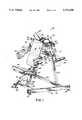
- FIG. 1is a perspective view of a lateral raise exercise machine in accordance with a preferred embodiment of the invention.
- FIG. 2is a top plan view of the lateral raise exercise machine shown in FIG. 1.
- FIG. 3is a side view of the lateral raise exercise machine shown in FIG. 1.
- FIG. 4is a perspective view, shown from the back, of the lateral raise exercise machine shown in FIG. 1.
- FIGS. 1-4show a lateral raise exercise machine 10 in accordance with a preferred embodiment of the invention.
- the machine 10includes a frame 11 of metal parts either connected together by nut and bolt connections or welds.
- the frame 11includes a backrest 14, a seat 15, and pivotal levers 17 and 18 which are pivotally connected to the frame 11 and located behind the backrest 14.
- the frame 11is supported by bottom side sections 21 and 22 which are interconnected with front and back bottom sections 23 and 24, respectively.
- side section 21is supported by plates 27 and 29, and side section 22 is supported by plates 28 and 30.
- Legs 33 and 34have bottom ends welded to back bottom section 24. Legs extend upwardly at an angle, with their top ends nearer to each other than the bottom ends.
- a center leg 35is welded at its bottom end to front and bottom section 23. The upper end of center leg 35 is supported by center plate 36. Center plate 36 is supported by rear plates 41 and 42 which are connected to the upper ends of legs 33 and 34, respectively. The forward portion of center plate 36 supports weights 43 and 44, which are parallel to, and in spaced relationship with plates 41 and 42, respectively.
- a brace 48is welded in horizontal disposition to the rear surface of center leg 35, and spaced uprights 49 and 50 extend upwardly from opposite sides of brace 48 to connect with plates 43 and 44, respectively.
- the lever 17also includes a connector 63 which extends forwardly alongside the seat 15 to support an actuating pad 65 that is acted upon by the exerciser (not shown) during performance of a lateral raise.
- An inner end of lever 17includes a counterweight 67 which substantially counterbalances the weight of the hub 57, the connector 63 and the pad 65 when no weighted plates 59 are held.
- lever 18includes a hub 58 for holding one or more weighted plates (not shown), a forwardly extending connector 64, an actuating pad 66 supported at the forward end of the connector 64 and a counterweight 68.
- the connector and the actuating padserve as an actuating means for performing a lateral raise exercise.
- FIG. 2also shows a rearward brace 71 that extends between legs 33 and 34. As best depicted in FIG. 4, the rearward brace 71 is connected to legs 33 and 34 by horizontally oriented rods 73 and 74, respectively. The ends of rearward brace 71 include rubber stops or bumpers 75 and 76. The stops 75 and 76 limit downward movement of levers 17 and 18, respectively.
- FIG. 2also shows the axes of pivotal movement of the levers, i.e., axis 79 for lever 17 and axis 80 for lever 18, each of which is non-parallel with the vertical midplane 70. These axes converge forwardly and tilt downwardly with respect to frame 11. This angle of forward convergence is designated by numeral 81 and is preferably about 8°.
- FIG. 3shows a side view of the frame 11.
- connector 63extends forwardly from the lever 17 at an angle designated by numeral 83, an angle which is preferably about 100°, or about 20° downward from horizontal.
- Legs 33 and 34also tilt downwardly about 2° toward the front of the frame 11, or toward the bottom side sections 21 and 22.
- Numeral 95designates the angle between bottom side section 21 and leg 33, an angle which is preferably about 88°. Because the plates 41 and 43 are parallel with leg 33, and because axle 53 is perpendicular with plates 41 and 43, axle 53 also tilts downwardly from horizontal at an angle of about 2°, an angle designated by numeral 96.
- the converging angle 81 and tilting angle 96 of the lever 17, along with the downward tilt of connector 63 toward the front of the frame 11locates the actuating pad 65 in a more natural position for an exerciser supported on the seat 15 and backrest 14.
- leg 34 and plates 42 and 44also tilt downwardly at the same angles.
- the orientation of the pivot axisprovides a natural position for coupling an applied lateral raise force to a forwardly and downwardly angled plane of motion.
- Numeral 84designates the angle between center leg 35 and the bottom sections of frame 11. Preferably, this angle is about 70°.
- Numeral 85designates the rearward tilt from horizontal of seat 15. Preferably this angle of rearward tilt is about 25°.
- seat 15is adjustable along leg 35. Adjustability is provided by mounting resilient, parallel members 87 and 88 on forward and rear portions, respectively, of leg 35. Parallel, spaced seat supports 89 and 90 are interconnected by parallel rods 91 and 92 which abut against and frictionally engage the outer surfaces of members 87 and 88, respectively, to maintain seat 15 in a selected position with respect to leg 35. Seat 15 is rigidly connected to a base 93 that is connected to seat supports 89 and 90.
- a forward edge of seat 15is lifted upwardly to provide clearance between rods 91 and 92 and members 87 and 88, respectively. With the forward edge held up in this manner, the seat 15 may be moved along center leg 35 to a desired location. When the forward edge of seat 15 is released, gravity will cause the seat 15 to rotate slightly in a forward direction until rods 91 and 92 frictionally engage plates members 87 and 88, respectively.
Landscapes
- Health & Medical Sciences (AREA)
- Orthopedic Medicine & Surgery (AREA)
- General Health & Medical Sciences (AREA)
- Physical Education & Sports Medicine (AREA)
- Life Sciences & Earth Sciences (AREA)
- Biophysics (AREA)
- Rehabilitation Tools (AREA)
Abstract
Description
Claims (13)
Priority Applications (1)
| Application Number | Priority Date | Filing Date | Title |
|---|---|---|---|
| US07/621,053US5171198A (en) | 1990-11-30 | 1990-11-30 | Lateral raise exercise machine |
Applications Claiming Priority (1)
| Application Number | Priority Date | Filing Date | Title |
|---|---|---|---|
| US07/621,053US5171198A (en) | 1990-11-30 | 1990-11-30 | Lateral raise exercise machine |
Publications (1)
| Publication Number | Publication Date |
|---|---|
| US5171198Atrue US5171198A (en) | 1992-12-15 |
Family
ID=24488521
Family Applications (1)
| Application Number | Title | Priority Date | Filing Date |
|---|---|---|---|
| US07/621,053Expired - LifetimeUS5171198A (en) | 1990-11-30 | 1990-11-30 | Lateral raise exercise machine |
Country Status (1)
| Country | Link |
|---|---|
| US (1) | US5171198A (en) |
Cited By (33)
| Publication number | Priority date | Publication date | Assignee | Title |
|---|---|---|---|---|
| US5409438A (en)* | 1987-06-11 | 1995-04-25 | Medx Corporation | Lateral raise exercise machine |
| WO1996009093A1 (en)* | 1994-09-22 | 1996-03-28 | Calibro Corporation | Deltoid muscle exercise device |
| US5554089A (en)* | 1994-09-16 | 1996-09-10 | Hammer Strength Corporation | Military press exercise machine |
| US5554084A (en)* | 1994-08-18 | 1996-09-10 | Hammer Strength Corporation | Abdominal/hip flex exercise machine |
| US5580341A (en)* | 1995-03-01 | 1996-12-03 | Lumex, Inc. | Shoulder press exercise machine and method of exercising |
| US6059701A (en)* | 1994-05-19 | 2000-05-09 | Cline Children Class Trust | Apparatus for exercising the lower back |
| WO2000078406A1 (en) | 1998-06-23 | 2000-12-28 | Brunswick Corporation | Multi-function exercise machine |
| US6533709B1 (en) | 1997-09-18 | 2003-03-18 | Brunswick Corp. | Standing push/pull exercise machine and method of using the same |
| USD497190S1 (en) | 2003-02-21 | 2004-10-12 | Cybex International, Inc. | Lateral raise exercise machine |
| US20040209746A1 (en)* | 2003-04-18 | 2004-10-21 | Amy Spiegel | Exercise machine and method for exercising the anterior deltoid muscle group |
| US20050009676A1 (en)* | 2003-07-11 | 2005-01-13 | Turnbull R. Gray | Exercise system for use within a vehicle |
| US20060035759A1 (en)* | 2004-08-16 | 2006-02-16 | Satterfield Artus L | Crank weights |
| US7070545B2 (en) | 2002-07-01 | 2006-07-04 | Nautilus, Inc. | Leg press and abdominal crunch exercise machine |
| US7070543B1 (en) | 2002-09-03 | 2006-07-04 | Randy Rindfleisch | Exercise machine with leverage arm |
| US7070544B1 (en) | 2003-01-30 | 2006-07-04 | Randy Rindfleisch | Isolation exercise machine with leverage arm |
| US7083554B1 (en) | 1997-02-27 | 2006-08-01 | Nautilus, Inc. | Exercise machine with infinite position range limiter and automatic belt tensioning system |
| US7086991B2 (en) | 2002-07-19 | 2006-08-08 | Michael Edward Williams | Rope climbing simulator |
| US7108641B2 (en) | 2000-05-03 | 2006-09-19 | Nautilus, Inc. | Exercise equipment with multi-positioning handles |
| US7115080B2 (en) | 2002-08-01 | 2006-10-03 | Nautilus, Inc. | Collapsible seat for combination hack squat and leg press machine |
| US7662074B2 (en) | 2004-10-04 | 2010-02-16 | Nautilus, Inc. | Exercise machine having rotatable weight selection index |
| US7736283B2 (en) | 2006-10-04 | 2010-06-15 | Nautilus, Inc. | Exercise machine having rotatable weight selection index |
| US7922635B2 (en) | 2000-03-10 | 2011-04-12 | Nautilus, Inc. | Adjustable-load unitary multi-position bench exercise unit |
| US8177695B2 (en)* | 2010-05-19 | 2012-05-15 | Fabio Dellino | Abdominal training machine and method |
| US8388499B1 (en) | 2009-06-30 | 2013-03-05 | Crazy Train, LLC | User controlled exercise machine |
| US8568279B2 (en) | 2010-03-31 | 2013-10-29 | Nautilus, Inc. | Engagement interface for an exercise machine |
| US8845498B2 (en) | 2010-03-31 | 2014-09-30 | Nautilus, Inc. | Lockout mechanism for a weight stack exercise machine |
| US8876674B2 (en) | 2010-03-31 | 2014-11-04 | Nautilus, Inc. | Selectable weight stack |
| US9017230B1 (en)* | 2013-03-13 | 2015-04-28 | Desmond Charlton Pitts | Upper body strengthening system |
| WO2017174872A1 (en)* | 2016-04-04 | 2017-10-12 | David Health Solutions Ltd. | Rehabilitation device and its use for exercising the shoulder region |
| KR102296498B1 (en)* | 2020-11-27 | 2021-09-01 | (주)뉴텍웰니스 | Lateral Raise Machine |
| US20240173590A1 (en)* | 2022-11-29 | 2024-05-30 | Jeffrey Rhein | Portable strength training equipment with variable lever system |
| KR20240086137A (en)* | 2022-12-09 | 2024-06-18 | 주식회사 대한스포츠 | Health machine for deltoid exercise |
| USD1084171S1 (en)* | 2023-03-15 | 2025-07-15 | Shandong Li De Fitness Co., Ltd | Machine for physical exercise |
Citations (4)
| Publication number | Priority date | Publication date | Assignee | Title |
|---|---|---|---|---|
| US3858873A (en)* | 1971-08-17 | 1975-01-07 | Arthur A Jones | Weight lifting exercising devices |
| US3998454A (en)* | 1973-05-15 | 1976-12-21 | Jones Arthur A | Force receiving exercising member |
| US4720099A (en)* | 1984-11-27 | 1988-01-19 | The Toro Company | Exercise machine |
| US4854578A (en)* | 1988-08-01 | 1989-08-08 | Fulks Kent B | Multi-purpose exercise machine |
- 1990
- 1990-11-30USUS07/621,053patent/US5171198A/ennot_activeExpired - Lifetime
Patent Citations (4)
| Publication number | Priority date | Publication date | Assignee | Title |
|---|---|---|---|---|
| US3858873A (en)* | 1971-08-17 | 1975-01-07 | Arthur A Jones | Weight lifting exercising devices |
| US3998454A (en)* | 1973-05-15 | 1976-12-21 | Jones Arthur A | Force receiving exercising member |
| US4720099A (en)* | 1984-11-27 | 1988-01-19 | The Toro Company | Exercise machine |
| US4854578A (en)* | 1988-08-01 | 1989-08-08 | Fulks Kent B | Multi-purpose exercise machine |
Non-Patent Citations (5)
| Title |
|---|
| Cybex Marketing brochure p. 4 Lateral Raise Titled Cybex Strength Systems Dec. 1989.* |
| Cybex Marketing brochure--p. 4--Lateral Raise Titled Cybex Strength Systems Dec. 1989. |
| High Intensity Strength Training Equipment, The Nautilus Book, pp. 151 & 153.* |
| Instruction Manual by Nautilus, p. 12.* |
| Nautilus Instruction Manual; Catalog Digest; Jun. 14, 1979; pp. 29 and 39.* |
Cited By (53)
| Publication number | Priority date | Publication date | Assignee | Title |
|---|---|---|---|---|
| US5409438A (en)* | 1987-06-11 | 1995-04-25 | Medx Corporation | Lateral raise exercise machine |
| US6059701A (en)* | 1994-05-19 | 2000-05-09 | Cline Children Class Trust | Apparatus for exercising the lower back |
| US5554084A (en)* | 1994-08-18 | 1996-09-10 | Hammer Strength Corporation | Abdominal/hip flex exercise machine |
| US5554089A (en)* | 1994-09-16 | 1996-09-10 | Hammer Strength Corporation | Military press exercise machine |
| WO1996009093A1 (en)* | 1994-09-22 | 1996-03-28 | Calibro Corporation | Deltoid muscle exercise device |
| US5540640A (en)* | 1994-09-22 | 1996-07-30 | Povilaitis; Darius A. | Deltoid muscle exercise device |
| US5788614A (en)* | 1995-03-01 | 1998-08-04 | Simonson; Roy | Plate-loaded chest press exercise machine and method of exercise |
| US5620402A (en)* | 1995-03-01 | 1997-04-15 | Cybex International, Inc. | Rear deltoid and rowing exercise machine and method of exercising |
| US5643152A (en)* | 1995-03-01 | 1997-07-01 | Cybex International, Inc. | Chest press exercise machine and method of exercising |
| US5667464A (en)* | 1995-03-01 | 1997-09-16 | Simonson; Roy | Plate-loaded shoulder press exercise machine and method of exercise |
| US5597375A (en)* | 1995-03-01 | 1997-01-28 | Simonson; Roy | Lat pulldown exercise machine and method of exercise |
| US5580341A (en)* | 1995-03-01 | 1996-12-03 | Lumex, Inc. | Shoulder press exercise machine and method of exercising |
| US7083554B1 (en) | 1997-02-27 | 2006-08-01 | Nautilus, Inc. | Exercise machine with infinite position range limiter and automatic belt tensioning system |
| US6533709B1 (en) | 1997-09-18 | 2003-03-18 | Brunswick Corp. | Standing push/pull exercise machine and method of using the same |
| WO2000078406A1 (en) | 1998-06-23 | 2000-12-28 | Brunswick Corporation | Multi-function exercise machine |
| US7922635B2 (en) | 2000-03-10 | 2011-04-12 | Nautilus, Inc. | Adjustable-load unitary multi-position bench exercise unit |
| US7608028B2 (en) | 2000-05-03 | 2009-10-27 | Nautilus, Inc. | Exercise equipment with multi-positioning handles |
| US7108641B2 (en) | 2000-05-03 | 2006-09-19 | Nautilus, Inc. | Exercise equipment with multi-positioning handles |
| US7608022B2 (en) | 2002-07-01 | 2009-10-27 | Nautilus, Inc. | Leg press and abdominal crunch exercise machine |
| US7070545B2 (en) | 2002-07-01 | 2006-07-04 | Nautilus, Inc. | Leg press and abdominal crunch exercise machine |
| US7086991B2 (en) | 2002-07-19 | 2006-08-08 | Michael Edward Williams | Rope climbing simulator |
| US7115080B2 (en) | 2002-08-01 | 2006-10-03 | Nautilus, Inc. | Collapsible seat for combination hack squat and leg press machine |
| US7070543B1 (en) | 2002-09-03 | 2006-07-04 | Randy Rindfleisch | Exercise machine with leverage arm |
| US20060205572A1 (en)* | 2003-01-30 | 2006-09-14 | Randy Rindfleisch | Isolation exercise machine with leverage arm |
| US7070544B1 (en) | 2003-01-30 | 2006-07-04 | Randy Rindfleisch | Isolation exercise machine with leverage arm |
| USD497190S1 (en) | 2003-02-21 | 2004-10-12 | Cybex International, Inc. | Lateral raise exercise machine |
| US7156793B2 (en) | 2003-04-18 | 2007-01-02 | Amy Spiegel | Exercise machine and method for exercising the anterior deltoid muscle group |
| US20040209746A1 (en)* | 2003-04-18 | 2004-10-21 | Amy Spiegel | Exercise machine and method for exercising the anterior deltoid muscle group |
| US7229392B2 (en)* | 2003-07-11 | 2007-06-12 | Turnbull R Gary | Exercise system for use within a vehicle |
| US20050009676A1 (en)* | 2003-07-11 | 2005-01-13 | Turnbull R. Gray | Exercise system for use within a vehicle |
| WO2005007247A3 (en)* | 2003-07-11 | 2005-10-06 | R Gary Turnbull | Exercise system for use within a vehicle |
| US7699762B2 (en) | 2003-07-11 | 2010-04-20 | Turnbull R Gary | Exercise system for use within a vehicle |
| US20050143231A1 (en)* | 2003-07-11 | 2005-06-30 | Turnbull R. G. | Exercise system for use within a vehicle |
| US20060035759A1 (en)* | 2004-08-16 | 2006-02-16 | Satterfield Artus L | Crank weights |
| US7662074B2 (en) | 2004-10-04 | 2010-02-16 | Nautilus, Inc. | Exercise machine having rotatable weight selection index |
| US7740568B2 (en) | 2004-10-04 | 2010-06-22 | Nautilus, Inc. | Exercise machine having rotatable weight selection index |
| US8016729B2 (en) | 2004-10-04 | 2011-09-13 | Nautilus, Inc. | Exercise machine having rotatable weight selection index |
| US7736283B2 (en) | 2006-10-04 | 2010-06-15 | Nautilus, Inc. | Exercise machine having rotatable weight selection index |
| US8388499B1 (en) | 2009-06-30 | 2013-03-05 | Crazy Train, LLC | User controlled exercise machine |
| US8845498B2 (en) | 2010-03-31 | 2014-09-30 | Nautilus, Inc. | Lockout mechanism for a weight stack exercise machine |
| US8568279B2 (en) | 2010-03-31 | 2013-10-29 | Nautilus, Inc. | Engagement interface for an exercise machine |
| US8876674B2 (en) | 2010-03-31 | 2014-11-04 | Nautilus, Inc. | Selectable weight stack |
| US8177695B2 (en)* | 2010-05-19 | 2012-05-15 | Fabio Dellino | Abdominal training machine and method |
| US9017230B1 (en)* | 2013-03-13 | 2015-04-28 | Desmond Charlton Pitts | Upper body strengthening system |
| US10881901B2 (en) | 2016-04-04 | 2021-01-05 | David Health Solutions Ltd. | Rehabilitation device and its use for exercising the shoulder region |
| CN108883332A (en)* | 2016-04-04 | 2018-11-23 | 戴维健康解决方案有限公司 | Rehabilitation device and its use for exercising the shoulder area |
| WO2017174872A1 (en)* | 2016-04-04 | 2017-10-12 | David Health Solutions Ltd. | Rehabilitation device and its use for exercising the shoulder region |
| CN108883332B (en)* | 2016-04-04 | 2021-05-25 | 戴维健康解决方案有限公司 | Rehabilitation device and its use for exercising the shoulder region |
| KR102296498B1 (en)* | 2020-11-27 | 2021-09-01 | (주)뉴텍웰니스 | Lateral Raise Machine |
| WO2022114616A1 (en)* | 2020-11-27 | 2022-06-02 | (주)뉴텍웰니스 | Lateral raise machine |
| US20240173590A1 (en)* | 2022-11-29 | 2024-05-30 | Jeffrey Rhein | Portable strength training equipment with variable lever system |
| KR20240086137A (en)* | 2022-12-09 | 2024-06-18 | 주식회사 대한스포츠 | Health machine for deltoid exercise |
| USD1084171S1 (en)* | 2023-03-15 | 2025-07-15 | Shandong Li De Fitness Co., Ltd | Machine for physical exercise |
Similar Documents
| Publication | Publication Date | Title |
|---|---|---|
| US5171198A (en) | Lateral raise exercise machine | |
| US5125881A (en) | Rear deltoid excercise machine | |
| US5554089A (en) | Military press exercise machine | |
| USRE35470E (en) | Incline press exercise machine | |
| US5044631A (en) | Decline press exercise machine | |
| US5044632A (en) | Dumbbell press exercise machine | |
| US5273504A (en) | Behind the neck pulldown exercise machine | |
| US5135449A (en) | Rowing exercise machine | |
| US5810701A (en) | Motion translation arrangement for exercise machine | |
| US5066003A (en) | Leg curl exercise machine | |
| US5273505A (en) | High row exercise machine | |
| US5180354A (en) | Rotary cuff exercise machine | |
| US7833138B1 (en) | Apparatus for bi-directional upper body exercise movements | |
| US5554084A (en) | Abdominal/hip flex exercise machine | |
| US5050873A (en) | Pulldown exercise machine | |
| US5135456A (en) | Low row exercise machine | |
| US6203474B1 (en) | Multi-function exercise machine | |
| US6394936B1 (en) | Convergent exercise machine and method | |
| US5106080A (en) | Leg press exercise machine | |
| US6010437A (en) | Standing push/pull exercise machine | |
| CA2230945A1 (en) | Upper body exercise machine | |
| US5788615A (en) | Body extension exercise machine | |
| KR102296498B1 (en) | Lateral Raise Machine | |
| US6656092B1 (en) | Method and apparatus for exercise with forced pronation or supination | |
| US20030092543A1 (en) | Upper torso exercise machine |
Legal Events
| Date | Code | Title | Description |
|---|---|---|---|
| AS | Assignment | Owner name:HAMMER CORPORATION, 2245 GILBERT AVE., CINCINNATI, Free format text:ASSIGNMENT OF ASSIGNORS INTEREST.;ASSIGNOR:JONES, GARY A.;REEL/FRAME:005583/0053 Effective date:19901206 | |
| AS | Assignment | Owner name:HAMMER STRENGTH CORPORATION Free format text:CHANGE OF NAME;ASSIGNOR:HAMMER CORPORATION;REEL/FRAME:005941/0365 Effective date:19910516 | |
| STCF | Information on status: patent grant | Free format text:PATENTED CASE | |
| AS | Assignment | Owner name:PNC BANK, OHIO, NATIONAL ASSOCIATION ATTN: METR Free format text:SECURITY INTEREST;ASSIGNOR:HAMMER STRENGTH CORPORATION;REEL/FRAME:006573/0326 Effective date:19930430 | |
| FPAY | Fee payment | Year of fee payment:4 | |
| AS | Assignment | Owner name:BRUNSWICK CORPORATION, ILLINOIS Free format text:ASSIGNMENT OF ASSIGNORS INTEREST;ASSIGNOR:HAMMER STRENGTH CORPORATION;REEL/FRAME:008907/0326 Effective date:19971112 Owner name:HAMMER STRENGTH CORPORATION, OHIO Free format text:RELEASE OF SECURITY INTEREST;ASSIGNOR:PNC BANK, OHIO, NATIONAL ASSOCIATION;REEL/FRAME:008896/0163 Effective date:19960818 | |
| FEPP | Fee payment procedure | Free format text:PAT HLDR NO LONGER CLAIMS SMALL ENT STAT AS SMALL BUSINESS (ORIGINAL EVENT CODE: LSM2); ENTITY STATUS OF PATENT OWNER: LARGE ENTITY | |
| FPAY | Fee payment | Year of fee payment:8 | |
| FPAY | Fee payment | Year of fee payment:12 |