US5171103A - Arrangement for expelling highly volatile impurities from ground water - Google Patents
Arrangement for expelling highly volatile impurities from ground waterDownload PDFInfo
- Publication number
- US5171103A US5171103AUS07/768,633US76863391AUS5171103AUS 5171103 AUS5171103 AUS 5171103AUS 76863391 AUS76863391 AUS 76863391AUS 5171103 AUS5171103 AUS 5171103A
- Authority
- US
- United States
- Prior art keywords
- nozzle body
- pipe
- arrangement
- pipe member
- well shaft
- Prior art date
- Legal status (The legal status is an assumption and is not a legal conclusion. Google has not performed a legal analysis and makes no representation as to the accuracy of the status listed.)
- Expired - Fee Related
Links
- 239000003673groundwaterSubstances0.000titleclaimsabstractdescription37
- 239000012535impuritySubstances0.000titleclaimsabstractdescription8
- XLYOFNOQVPJJNP-UHFFFAOYSA-NwaterSubstancesOXLYOFNOQVPJJNP-UHFFFAOYSA-N0.000claimsabstractdescription20
- 239000002689soilSubstances0.000claimsabstractdescription5
- 238000004140cleaningMethods0.000claimsdescription11
- 238000010276constructionMethods0.000description2
- 239000007788liquidSubstances0.000description2
- 238000004873anchoringMethods0.000description1
- 230000015572biosynthetic processEffects0.000description1
- 150000008280chlorinated hydrocarbonsChemical class0.000description1
- 239000000356contaminantSubstances0.000description1
- 230000002349favourable effectEffects0.000description1
- 238000000034methodMethods0.000description1
- 238000012986modificationMethods0.000description1
- 230000004048modificationEffects0.000description1
- 230000000630rising effectEffects0.000description1
- 125000006850spacer groupChemical group0.000description1
Images
Classifications
- C—CHEMISTRY; METALLURGY
- C02—TREATMENT OF WATER, WASTE WATER, SEWAGE, OR SLUDGE
- C02F—TREATMENT OF WATER, WASTE WATER, SEWAGE, OR SLUDGE
- C02F1/00—Treatment of water, waste water, or sewage
- C02F1/58—Treatment of water, waste water, or sewage by removing specified dissolved compounds
- C02F1/62—Heavy metal compounds
- C02F1/64—Heavy metal compounds of iron or manganese
- C02F1/645—Devices for iron precipitation and treatment by air
- C—CHEMISTRY; METALLURGY
- C02—TREATMENT OF WATER, WASTE WATER, SEWAGE, OR SLUDGE
- C02F—TREATMENT OF WATER, WASTE WATER, SEWAGE, OR SLUDGE
- C02F1/00—Treatment of water, waste water, or sewage
- C02F1/20—Treatment of water, waste water, or sewage by degassing, i.e. liberation of dissolved gases
Definitions
- the inventionis directed to an arrangement for expelling highly volatile impurities from the ground water and the soil through which the latter flows. More particularly, it relates to an arrangement for expelling highly volatile impurities from the ground water and the soil through which the water flows by means of producing a vacuum in a well shaft which is driven into the area of the contaminated ground water and by means of directing a gas below the water level into the well shaft.
- Such an arrangementis already known from DE-PS No. 38 11 962.
- a vertical flow of ground water in the well shaftcan be benefitted by means of this arrangement.
- the object of the inventionis to develop an arrangement of this kind in such a way that the vertical flow of ground water is more greatly benefitted and also controllable.
- a nozzle bodyis provided for distributing the supplied gas along the well shaft cross-section via an upper defining wall of the nozzle body provided with through-openings
- the nozzle bodyis arranged below the water level and defines an air chamber and also is held by means of a floating body
- a pipewhich is guided centrally relative to the nozzle body for guiding air and is securely connected with the nozzle body
- the pipehas at least one air outlet opening in the area of the air chamber of the nozzle body
- the pipehas a continuation pipe area for guiding water down and out via the nozzle body, a conveyor screw is arranged in this pipe area
- the continuation pipeis additionally provided with at least one water through-opening in the area between the nozzle body and the conveyor screw.
- the driven conveyor screw located in the pipe arranged below the nozzle body in the ground water areacan produce a liquid movement in the well shaft below the nozzle body and accordingly also below the cleaning area of the well shaft.
- This liquid flowconveys ground water either downward out of the cleaning area or upward from the bottom into the cleaning area -- depending on the rotating direction of the conveyor screw -- which then compulsorily triggers a counter-movement of ground water either back toward the top or back toward the bottom from the upper cleaning area and accelerates the exchange of cleaned ground water and contaminated ground water in the cleaning area.
- This arrangementhas proven particularly advantageous in cases where impurities are concentrated in deeper layers of earth through which ground water flows and where precautions must be taken against higher layers of earth being additionally contaminated subsequently when driving a well shaft.
- an intermediate floorcan be inserted in the well shaft above the more heavily contaminated layers of earth.
- the continuation part of the pipe provided with the conveyor screwis guided through this intermediate floor and allows contaminated ground water to be conveyed upward from below the intermediate floor in an advisably metered manner into the cleaning area of the well shaft located above the nozzle body.
- a continuous pipewhich serves to guide air up into the nozzle body and to guide water below the latter and comprises corresponding openings for the passage of air and for the passage of water.
- the pipecan also be divided into its air-guiding portion, its water-guiding portion and continuation portion which is provided with the conveyor screw, wherein the divided portions can also have different diameters.
- the conveyor screwcan be advantageously arranged on a shaft which is guided concentrically in the pipe and connected with a motor placed on the upper end of the pipe.
- a guide ringcan be fastened at the pipe above the nozzle body at a distance from the latter and concentric to and at a distance from the pipe.
- the guide ringbenefits a rising of the ground water in the interior of the shaft area penetrated by air in the cleaning area and a return flow of the ground water in the outer area near the wall of the shaft.
- an additional guide ringcan also be arranged concentric to and at a distance from the nozzle body. The additional guide ring influences the ground water flow in the area of the nozzle body.
- This additional guide ringcan be connected at the bottom with the waterguiding continuation part of the pipe by means of a base extending at a distance from the nozzle body and can accordingly form a catch basin for the purified ground water which is to be guided down by means of the conveyor screw.
- the continuation part of the pipecan serve simultaneously as a guide for an intermediate floor of the well shaft, which has already been mentioned.
- At least one inflatable clamping hosecan be fastened in an advantageous manner at the outer pot wall of the intermediate floor insert, which is advisably constructed in a pot-shaped manner, as fastening member for anchoring the intermediate floor at the well shaft wall.
- the nozzle bodycan be penetrated by nozzle shafts which are known from DE-PS No. 38 11 962 and are provided with air inlet openings in their walls in the area of the air chamber and can exert an additional suction action on the ground water in the area of the nozzle body.
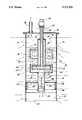
- FIGURE of the drawingsis a view schematically showing a longitudinal section of an arrangement for expelling highly volatile impurities in accordance with the present invention.
- a well shaft 10which leads into ground water and is driven e.g. through soil 11 which is contaminated by chlorinated hydrocarbons is faced partly with closed pipe portions 12 and partly with water-permeable sieve pipe portions 13.
- the upper end of the well shaft 10is closed by a cover 14.
- a central opening 15 for the free passage of a central pipe 16 and an eccentrically positioned opening 17 for a suction pipeare formed in the cover 14.
- the suction pipe 18leads to a ventilator, not shown, by means of which a vacuum is produced in the well shaft above the ground water table 19 formed in the latter.
- the arrangement for expelling highly volatile contaminants from the ground water 20 collecting in the well shaftis inserted into the well shaft 10. It primarily has a nozzle body 21 whose upper defining wall 21.1 is provided with nozzle openings 22.
- the nozzle body 21is fastened at the lower end of the central pipe 16 air can flow in through the central pipe 16 and particularly through upper outer openings 23 into the interior 24 of the nozzle body, air then rises up through the nozzle openings 22 through the ground water 20 in the form of fine bubbles 25 under the action of the vacuum 10 produced above the ground water level 19.
- An annular floating body 26which holds the nozzle body 21 so as to float at a desired distance from the water level 19 is constructed around the central pipe 16.
- the central pipe 16continues below the nozzle body 21 in a central pipe portion or pipe member 27 which is located entirely in the ground water area.
- a conveyor screw 28is arranged in this pipe member.
- the conveyor screw 28is fastened on a shaft 29 which is guided through the pipe member 27, the nozzle body 21 and the pipe 16 and is driven by a drive motor 30 placed on the upper outer end of the pipe 16.
- the pipe 16 and the pipe member 27can also consist of a continuous pipe in one piece which would have to comprise air outlet openings in the area of the nozzle body 21 and ground water through-openings below the latter.
- the lower pipe portionis fastened in a central water through-opening 31 of a base wall 32 of a guide ring 33 which extends concentric to and at a distance from the nozzle body 21 and is fastened at the nozzle body 21 by means of retaining webs, not shown.
- a guide ring 34is arranged above the nozzle body 21 so as to be concentric to the pipe 26 and is fastened at the floating body 26 by means of individual spacer webs, not shown.
- the pipe member 27is guided through a central opening 35 of an intermediate floor 36 so as to be freely movable.
- the intermediate floor 36is arranged in the well shaft 10. and constructed in a pot-shaped manner. Its pot wall 37, which extends parallel to the shaft walls, is provided at the outside with two inflatable clamping hoses 38.
- the hoses 38are inflatable via hose lines, not shown, and fasten the intermediate floor 36 at the well shaft wall.
- Flow arrowsshow the through-flow of air in the arrangement and in the well shaft caused by the vacuum, as well as the flowing of ground water through the sieve wall portions 13 of the well shaft and inside the well shaft under the action of a vacuum in the well shaft.
- the vertical flow of the ground wateris increased in the well shaft by means of the conveyor screw 28.
- a suction of ground water from the cleaning area located above the sieve body 21 downward through the pipe portion 27is indicated in the drawing.
- the ground watercan also be conveyed from below the intermediate floor 36 upward into the cleaning area of the arrangement by reversing the direction of rotation of the conveyor screw 28.
- eccentric additional nozzle shaftssuch as are shown and described in DE-PS No. 38 11 962, can be arranged in the nozzle body.
Landscapes
- Life Sciences & Earth Sciences (AREA)
- Hydrology & Water Resources (AREA)
- Engineering & Computer Science (AREA)
- Environmental & Geological Engineering (AREA)
- Water Supply & Treatment (AREA)
- Chemical & Material Sciences (AREA)
- Organic Chemistry (AREA)
- Processing Of Solid Wastes (AREA)
- Physical Water Treatments (AREA)
Abstract
Description
Claims (11)
Applications Claiming Priority (2)
| Application Number | Priority Date | Filing Date | Title |
|---|---|---|---|
| DE3910990ADE3910990C1 (en) | 1989-04-05 | 1989-04-05 | |
| DE3910990 | 1989-04-05 |
Publications (1)
| Publication Number | Publication Date |
|---|---|
| US5171103Atrue US5171103A (en) | 1992-12-15 |
Family
ID=6377903
Family Applications (1)
| Application Number | Title | Priority Date | Filing Date |
|---|---|---|---|
| US07/768,633Expired - Fee RelatedUS5171103A (en) | 1989-04-05 | 1990-03-24 | Arrangement for expelling highly volatile impurities from ground water |
Country Status (5)
| Country | Link |
|---|---|
| US (1) | US5171103A (en) |
| EP (1) | EP0466721B1 (en) |
| DE (1) | DE3910990C1 (en) |
| ES (1) | ES2049470T3 (en) |
| WO (1) | WO1990011811A1 (en) |
Cited By (14)
| Publication number | Priority date | Publication date | Assignee | Title |
|---|---|---|---|---|
| US5345655A (en)* | 1992-02-19 | 1994-09-13 | Ieg Industrie-Engineering Gmbh | Method of and arrangement for obtaining liquids and/or gases from ground or rock layers |
| US5348420A (en)* | 1991-12-24 | 1994-09-20 | Ieg Industrie-Engineering Gmbh | Method and arrangement for influencing liquid in ground |
| US5380126A (en)* | 1992-06-03 | 1995-01-10 | Ieg Industrie-Engineering Gmbh | Method of and arrangement for rinsing out impurities from ground |
| US5383747A (en)* | 1993-08-23 | 1995-01-24 | International Technology Corporation | System for treating a subterranean formation having an aquifer contaminated with organics |
| US5403476A (en)* | 1992-05-29 | 1995-04-04 | Ieg Industrie-Engineering Gmbh | Arrangement for removing impurities from ground water |
| US5439594A (en)* | 1993-06-23 | 1995-08-08 | Geraghty & Miller, Inc. | Method for subsurface vapor extraction |
| US5613242A (en)* | 1994-12-06 | 1997-03-18 | Oddo; John E. | Method and system for disposing of radioactive solid waste |
| US5622450A (en)* | 1995-03-24 | 1997-04-22 | Grant, Jr.; Richard P. | Pressure extraction process for removing soil and groundwater contaminants |
| US5795474A (en)* | 1995-03-06 | 1998-08-18 | Tolan; Peter J. | Method and apparatus for the separation of hazardous waste from groundwater |
| US6102623A (en) | 1997-05-19 | 2000-08-15 | Arcadis Geraghty & Miller, Inc. | In-well air stripping, oxidation, and adsorption |
| US6116816A (en) | 1998-08-26 | 2000-09-12 | Arcadis Geraghty & Miller, Inc. | In situ reactive gate for groundwater remediation |
| US6143177A (en) | 1995-04-11 | 2000-11-07 | Arcadis Geraghty & Miller, Inc. | Engineered in situ anaerobic reactive zones |
| RU2370455C1 (en)* | 2008-03-18 | 2009-10-20 | Государственное унитарное предприятие города Москвы "Институт МосводоканалНИИпроект" | Device for water deironing |
| US8101089B2 (en) | 2007-08-15 | 2012-01-24 | Liquid Separation Technologies And Equipment, Llc | Apparatus for aeration of contaminated liquids |
Families Citing this family (4)
| Publication number | Priority date | Publication date | Assignee | Title |
|---|---|---|---|---|
| DE4017642C1 (en)* | 1990-05-31 | 1991-12-12 | Santec Gmbh Ingenieurbuero Fuer Sanierungstechnologien, 1000 Berlin, De | |
| DE4027304C2 (en)* | 1990-08-29 | 1993-12-09 | Ieg Ind Engineering Gmbh | Arrangement for expelling volatile contaminants from the groundwater |
| DE4039824C1 (en)* | 1990-12-13 | 1991-12-19 | Ieg - Industrie-Engineering Gmbh, 7410 Reutlingen, De | |
| DE4204059C2 (en)* | 1992-02-07 | 1994-05-05 | Koester Hans Herbert Dipl Geol | Remediation wells for removing groundwater contamination |
Citations (6)
| Publication number | Priority date | Publication date | Assignee | Title |
|---|---|---|---|---|
| GB782823A (en)* | 1953-08-04 | 1957-09-11 | Smith Paper Mills Ltd Howard | Method and apparatus for separating dirt from aqueous suspensions of pulp fibres |
| FR1167397A (en)* | 1956-03-03 | 1958-11-24 | C Aug Schmidt Sohne | Thermal degasser for liquids, in particular for boiler feed water |
| US4045336A (en)* | 1974-08-23 | 1977-08-30 | Pauli Henrik Isteri | Method and device for oxygenating water with vibrations and under pressure strokes |
| US4632601A (en)* | 1985-11-01 | 1986-12-30 | Kuwada James T | System and method for disposal of noncondensable gases from geothermal wells |
| US4850745A (en)* | 1988-06-17 | 1989-07-25 | Sybron Chemicals, Inc. | Bioremediation system |
| US4943305A (en)* | 1988-06-23 | 1990-07-24 | Bruno Bernhardt | Aerating apparatus for expelling volatile impurities from ground water |
Family Cites Families (2)
| Publication number | Priority date | Publication date | Assignee | Title |
|---|---|---|---|---|
| DE3805200C1 (en)* | 1988-02-19 | 1988-09-29 | Ieg - Industrie-Engineering Gmbh, 7410 Reutlingen, De | Arrangement for expelling readily volatile impurities from groundwater |
| DE3811962C1 (en)* | 1988-04-11 | 1989-02-16 | Ieg - Industrie-Engineering Gmbh, 7410 Reutlingen, De | Arrangement for expelling highly volatile impurities from ground water |
- 1989
- 1989-04-05DEDE3910990Apatent/DE3910990C1/denot_activeExpired
- 1990
- 1990-03-24ESES90904820Tpatent/ES2049470T3/ennot_activeExpired - Lifetime
- 1990-03-24EPEP90904820Apatent/EP0466721B1/ennot_activeExpired - Lifetime
- 1990-03-24USUS07/768,633patent/US5171103A/ennot_activeExpired - Fee Related
- 1990-03-24WOPCT/EP1990/000479patent/WO1990011811A1/enactiveIP Right Grant
Patent Citations (6)
| Publication number | Priority date | Publication date | Assignee | Title |
|---|---|---|---|---|
| GB782823A (en)* | 1953-08-04 | 1957-09-11 | Smith Paper Mills Ltd Howard | Method and apparatus for separating dirt from aqueous suspensions of pulp fibres |
| FR1167397A (en)* | 1956-03-03 | 1958-11-24 | C Aug Schmidt Sohne | Thermal degasser for liquids, in particular for boiler feed water |
| US4045336A (en)* | 1974-08-23 | 1977-08-30 | Pauli Henrik Isteri | Method and device for oxygenating water with vibrations and under pressure strokes |
| US4632601A (en)* | 1985-11-01 | 1986-12-30 | Kuwada James T | System and method for disposal of noncondensable gases from geothermal wells |
| US4850745A (en)* | 1988-06-17 | 1989-07-25 | Sybron Chemicals, Inc. | Bioremediation system |
| US4943305A (en)* | 1988-06-23 | 1990-07-24 | Bruno Bernhardt | Aerating apparatus for expelling volatile impurities from ground water |
Cited By (21)
| Publication number | Priority date | Publication date | Assignee | Title |
|---|---|---|---|---|
| US5348420A (en)* | 1991-12-24 | 1994-09-20 | Ieg Industrie-Engineering Gmbh | Method and arrangement for influencing liquid in ground |
| US5345655A (en)* | 1992-02-19 | 1994-09-13 | Ieg Industrie-Engineering Gmbh | Method of and arrangement for obtaining liquids and/or gases from ground or rock layers |
| US5403476A (en)* | 1992-05-29 | 1995-04-04 | Ieg Industrie-Engineering Gmbh | Arrangement for removing impurities from ground water |
| US5380126A (en)* | 1992-06-03 | 1995-01-10 | Ieg Industrie-Engineering Gmbh | Method of and arrangement for rinsing out impurities from ground |
| US5439594A (en)* | 1993-06-23 | 1995-08-08 | Geraghty & Miller, Inc. | Method for subsurface vapor extraction |
| US5383747A (en)* | 1993-08-23 | 1995-01-24 | International Technology Corporation | System for treating a subterranean formation having an aquifer contaminated with organics |
| US5613242A (en)* | 1994-12-06 | 1997-03-18 | Oddo; John E. | Method and system for disposing of radioactive solid waste |
| US5795474A (en)* | 1995-03-06 | 1998-08-18 | Tolan; Peter J. | Method and apparatus for the separation of hazardous waste from groundwater |
| US5622450A (en)* | 1995-03-24 | 1997-04-22 | Grant, Jr.; Richard P. | Pressure extraction process for removing soil and groundwater contaminants |
| US6632364B1 (en) | 1995-04-11 | 2003-10-14 | Arcadis G & M | Engineered in situ anaerobic reactive zones |
| US6322700B1 (en) | 1995-04-11 | 2001-11-27 | Arcadis Geraghty & Miller | Engineered in situ anaerobic reactive zones |
| US6143177A (en) | 1995-04-11 | 2000-11-07 | Arcadis Geraghty & Miller, Inc. | Engineered in situ anaerobic reactive zones |
| US6283674B1 (en)* | 1997-05-19 | 2001-09-04 | Arcadis Geraghty & Miller | In-well air stripping, oxidation, and adsorption |
| US6254310B1 (en) | 1997-05-19 | 2001-07-03 | Arcadis Geraghty & Miller, Inc. | In-well air stripping and adsorption |
| US6174108B1 (en)* | 1997-05-19 | 2001-01-16 | Arcadis Geraghty & Miller, Inc. | In-well air stripping and gas adsorption |
| US6102623A (en) | 1997-05-19 | 2000-08-15 | Arcadis Geraghty & Miller, Inc. | In-well air stripping, oxidation, and adsorption |
| US6280118B1 (en) | 1998-08-26 | 2001-08-28 | Arcadis Geraghty & Miller, Inc. | In situ reactive gate |
| US6116816A (en) | 1998-08-26 | 2000-09-12 | Arcadis Geraghty & Miller, Inc. | In situ reactive gate for groundwater remediation |
| US8101089B2 (en) | 2007-08-15 | 2012-01-24 | Liquid Separation Technologies And Equipment, Llc | Apparatus for aeration of contaminated liquids |
| US9079785B2 (en) | 2007-08-15 | 2015-07-14 | Liquid Separation Technologies And Equipment, Llc | Apparatus for aeration of contaminated liquids |
| RU2370455C1 (en)* | 2008-03-18 | 2009-10-20 | Государственное унитарное предприятие города Москвы "Институт МосводоканалНИИпроект" | Device for water deironing |
Also Published As
| Publication number | Publication date |
|---|---|
| EP0466721A1 (en) | 1992-01-22 |
| EP0466721B1 (en) | 1994-02-23 |
| ES2049470T3 (en) | 1994-04-16 |
| DE3910990C1 (en) | 1989-12-21 |
| WO1990011811A1 (en) | 1990-10-18 |
Similar Documents
| Publication | Publication Date | Title |
|---|---|---|
| US5171103A (en) | Arrangement for expelling highly volatile impurities from ground water | |
| US4950394A (en) | Arrangement for driving out volatile impurities from ground water | |
| US4278546A (en) | Treatment of a liquid by circulation and gas contacting | |
| US5095975A (en) | Arrangement for driving volatile impurities from ground water | |
| US5085809A (en) | Apparatus for gas absorption in a liquid | |
| RU1811422C (en) | Machine for flotation of minerals or analogous materials from pulp | |
| US4259267A (en) | Aeration apparatus by means of vortex action | |
| US4618426A (en) | Retrievable jet mixing systems | |
| KR880004759A (en) | Beverage making equipment | |
| US2669440A (en) | Apparatus for the aeration of water for purification purposes | |
| US4200597A (en) | Device for revolving liquids and supplying gas thereto | |
| US4139579A (en) | Apparatus for introducing air into a liquid including a liquid pump mounted within an aerator pressure chamber | |
| US2616676A (en) | Aerator | |
| US4940534A (en) | Froth flotation column | |
| US4859325A (en) | Waste material treatment apparatus | |
| US20070193955A1 (en) | Aquarium protein skimmer | |
| CA2100638C (en) | Aerator device | |
| GB1424245A (en) | Device for dissolving a poorly soluble gas in a liquid | |
| US706473A (en) | Dish-washing machine. | |
| US4189384A (en) | Gas treatment of liquid | |
| EP0602762B1 (en) | Apparatus for dissolving gas in a liquid | |
| RU2038332C1 (en) | Liquid aerating equipment | |
| US4049549A (en) | Liquid condition and settling tanks | |
| US3862279A (en) | Subsurface aerator and mixer | |
| US4720361A (en) | Immersible aerator and/or mixer apparatus |
Legal Events
| Date | Code | Title | Description |
|---|---|---|---|
| FEPP | Fee payment procedure | Free format text:PAYOR NUMBER ASSIGNED (ORIGINAL EVENT CODE: ASPN); ENTITY STATUS OF PATENT OWNER: SMALL ENTITY | |
| FPAY | Fee payment | Year of fee payment:4 | |
| AS | Assignment | Owner name:PARIBAS, TEXAS Free format text:SECURITY INTEREST;ASSIGNOR:MACTEC, INC.;REEL/FRAME:010175/0953 Effective date:19990624 Owner name:MACTEC, INC., COLORADO Free format text:ASSIGNMENT OF ASSIGNORS INTEREST;ASSIGNOR:INDUSTRIE-ENGINEERING GMBH, A/K/A IEGMBH;REEL/FRAME:010180/0155 Effective date:19990628 | |
| AS | Assignment | Owner name:MACTEC ENVIRONMENTAL TECHNOLOGIES COMPANY, L.L.C., Free format text:ASSIGNMENT OF ASSIGNORS INTEREST;ASSIGNOR:MACTEC, INC.;REEL/FRAME:010188/0001 Effective date:19990707 | |
| AS | Assignment | Owner name:PARIBAS, TEXAS Free format text:ASSIGNMENT OF ASSIGNORS INTEREST;ASSIGNOR:MACTEC ENVIRONMENTAL TECHNOLOGIES COMPANY, L.L.C.;REEL/FRAME:010247/0434 Effective date:19990826 | |
| AS | Assignment | Owner name:INDUSTRIE-ENGINEERING GMBH, GERMANY Free format text:ASSIGNMENT OF ASSIGNORS INTEREST;ASSIGNOR:MACTEC ENVIRONMENTAL TECHNOLOGIES COMPANY, L.L.C.;REEL/FRAME:010927/0736 Effective date:20000621 | |
| REMI | Maintenance fee reminder mailed | ||
| LAPS | Lapse for failure to pay maintenance fees | ||
| FP | Lapsed due to failure to pay maintenance fee | Effective date:20001215 | |
| STCH | Information on status: patent discontinuation | Free format text:PATENT EXPIRED DUE TO NONPAYMENT OF MAINTENANCE FEES UNDER 37 CFR 1.362 |