US5170817A - Support device for fluid delivery system and case therefore - Google Patents
Support device for fluid delivery system and case thereforeDownload PDFInfo
- Publication number
- US5170817A US5170817AUS07/679,886US67988691AUS5170817AUS 5170817 AUS5170817 AUS 5170817AUS 67988691 AUS67988691 AUS 67988691AUS 5170817 AUS5170817 AUS 5170817A
- Authority
- US
- United States
- Prior art keywords
- support device
- compartment
- container
- pump
- rigid body
- Prior art date
- Legal status (The legal status is an assumption and is not a legal conclusion. Google has not performed a legal analysis and makes no representation as to the accuracy of the status listed.)
- Expired - Lifetime
Links
Images


Classifications
- A—HUMAN NECESSITIES
- A61—MEDICAL OR VETERINARY SCIENCE; HYGIENE
- A61M—DEVICES FOR INTRODUCING MEDIA INTO, OR ONTO, THE BODY; DEVICES FOR TRANSDUCING BODY MEDIA OR FOR TAKING MEDIA FROM THE BODY; DEVICES FOR PRODUCING OR ENDING SLEEP OR STUPOR
- A61M5/00—Devices for bringing media into the body in a subcutaneous, intra-vascular or intramuscular way; Accessories therefor, e.g. filling or cleaning devices, arm-rests
- A61M5/14—Infusion devices, e.g. infusing by gravity; Blood infusion; Accessories therefor
- A61M5/1413—Modular systems comprising interconnecting elements
- A—HUMAN NECESSITIES
- A61—MEDICAL OR VETERINARY SCIENCE; HYGIENE
- A61M—DEVICES FOR INTRODUCING MEDIA INTO, OR ONTO, THE BODY; DEVICES FOR TRANSDUCING BODY MEDIA OR FOR TAKING MEDIA FROM THE BODY; DEVICES FOR PRODUCING OR ENDING SLEEP OR STUPOR
- A61M5/00—Devices for bringing media into the body in a subcutaneous, intra-vascular or intramuscular way; Accessories therefor, e.g. filling or cleaning devices, arm-rests
- A61M5/14—Infusion devices, e.g. infusing by gravity; Blood infusion; Accessories therefor
- A61M5/1414—Hanging-up devices
- A61M5/1415—Stands, brackets or the like for supporting infusion accessories
- A—HUMAN NECESSITIES
- A61—MEDICAL OR VETERINARY SCIENCE; HYGIENE
- A61M—DEVICES FOR INTRODUCING MEDIA INTO, OR ONTO, THE BODY; DEVICES FOR TRANSDUCING BODY MEDIA OR FOR TAKING MEDIA FROM THE BODY; DEVICES FOR PRODUCING OR ENDING SLEEP OR STUPOR
- A61M2205/00—General characteristics of the apparatus
- A61M2205/60—General characteristics of the apparatus with identification means
- A61M2205/6018—General characteristics of the apparatus with identification means providing set-up signals for the apparatus configuration
- A—HUMAN NECESSITIES
- A61—MEDICAL OR VETERINARY SCIENCE; HYGIENE
- A61M—DEVICES FOR INTRODUCING MEDIA INTO, OR ONTO, THE BODY; DEVICES FOR TRANSDUCING BODY MEDIA OR FOR TAKING MEDIA FROM THE BODY; DEVICES FOR PRODUCING OR ENDING SLEEP OR STUPOR
- A61M2209/00—Ancillary equipment
- A61M2209/08—Supports for equipment
- Y—GENERAL TAGGING OF NEW TECHNOLOGICAL DEVELOPMENTS; GENERAL TAGGING OF CROSS-SECTIONAL TECHNOLOGIES SPANNING OVER SEVERAL SECTIONS OF THE IPC; TECHNICAL SUBJECTS COVERED BY FORMER USPC CROSS-REFERENCE ART COLLECTIONS [XRACs] AND DIGESTS
- Y10—TECHNICAL SUBJECTS COVERED BY FORMER USPC
- Y10S—TECHNICAL SUBJECTS COVERED BY FORMER USPC CROSS-REFERENCE ART COLLECTIONS [XRACs] AND DIGESTS
- Y10S128/00—Surgery
- Y10S128/12—Pressure infusion
- Y—GENERAL TAGGING OF NEW TECHNOLOGICAL DEVELOPMENTS; GENERAL TAGGING OF CROSS-SECTIONAL TECHNOLOGIES SPANNING OVER SEVERAL SECTIONS OF THE IPC; TECHNICAL SUBJECTS COVERED BY FORMER USPC CROSS-REFERENCE ART COLLECTIONS [XRACs] AND DIGESTS
- Y10—TECHNICAL SUBJECTS COVERED BY FORMER USPC
- Y10T—TECHNICAL SUBJECTS COVERED BY FORMER US CLASSIFICATION
- Y10T137/00—Fluid handling
- Y10T137/6851—With casing, support, protector or static constructional installations
- Y10T137/6918—With hose storage or retrieval means
- Y10T137/6962—Basket or holder for folded coiled hose
Definitions
- This inventionrelates generally to a fluid delivery system. More specifically, the present invention relates to a support device used as a part of a fluid delivery system for supporting and protecting elements thereof, e.g. pump, fluid container, tubing, drip chamber, etc. of a fluid infusion system.
- a support deviceused as a part of a fluid delivery system for supporting and protecting elements thereof, e.g. pump, fluid container, tubing, drip chamber, etc. of a fluid infusion system.
- a further improvementhas been to develop an infusion system which can not only automatically infuse preset volumes of fluid into the patient on a predetermined time table, but also allow the patient to be ambulatory.
- U.S. Pat. No. 4,657,486 to Stemple et al.is exemplary of portable infusion systems of this type. Stemple discloses a portable infusion device which is automatically operable at selected time intervals to inject accurate amounts of fluid medication into a patient's body, and is also sufficiently compact and portable to allow the patient to be ambulatory while being attached to the infusion system.
- U.S. Pat. No. 4,688,595 to Srebnik et al.is also exemplary of fluid delivery systems of this type.
- Srebnikdiscloses a delivery system which includes an integrally molded base to which elements of the delivery system, i.e., the pump, the fluid container, etc. can be connected.
- the baseallows the entire fluid delivery system to be transportable as a unit and makes it possible for the patient to move about without the inconvenience of transporting a more cumbersome apparatus such as a prior art type infusion system affixed to a pole mounted on wheels.
- fluid infusion systemsgenerally include a programmable pump and a fluid delivery set comprising a fluid container, tubing, a pinch clamp, a drip chamber, etc. all connected as an integral unit.
- the container of the fluid delivery setsmay be a flexible bag, a rigid glass or plastic bottle or a burette.
- standard fluid delivery setsi.e. sets intended for non-ambulatory use
- These setsare generally ill suited for placement in a portable device such as that described by Srebnik et al.
- the present inventionprovides for ambulatory use of a "standard" pump and fluid delivery set of a fluid delivery system while reliably preventing kinking or occlusion of excess tubing thereof and other inadvertent damage to the system.
- a support deviceformed of a rigid body having a receptacle for receiving and locking a standard infusion pump in place therein, and a generically-shaped area for receiving and retaining a container of a fluid delivery set in a fixed position relative to the pump.
- the support devicealso includes an elongated channel extending around a substantial portion of the perimeter of the rigid body into which the tubing of the fluid delivery set can be inserted.
- the elongate channelis designed to match the length of the tubing included on a "standard" fluid delivery set so that tubing between the container and the pump is protected against kinking or occlusion along its entire length.
- the rigid bodyalso includes straps, brackets, and clamps which are strategically positioned to provide maximum support for anyone of several types of containers, such as soft bags, glass bottles, blow molded plastic bottles, burettes, etc.
- the rigid bodyalso includes a base which can be used to support the entire fluid delivery system, and which may include extendable legs to increase the stability thereof.
- the rigid bodymay include a hole which allows it to be suspended from a standard infusion pole.
- a carrying case designed to allow ready access to operation of the pump or visualization of fluid levels in the containercan be placed about the support device.
- the casemay include a strap or other type of handle to allow the patient to transport the entire fluid delivery system without concern for kinking or occlusion of the fluid set tubing, or for other damage to the system.
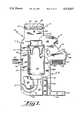
- FIG. 1is a front view of a support device made in accordance with the principles of the present invention
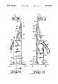
- FIG. 2is a side view of the support device of FIG. 1;
- FIG. 3is a side view of the support device of FIG. 1 opposite the side view of FIG. 2;
- FIG. 4is a cross-sectional view of the tube channel of the support device taken along line IV--IV of FIG. 3;
- FIGS. 5(a-d)are perspective views of a preferred embodiment of the support device of the present invention showing a pump and fluid set of a fluid delivery system in various stages of attachment and assembly to the support device;
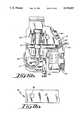
- FIG. 6(a)is a front view of a support device made in accordance with the principles of the present invention including a soft bag-type container of a fluid delivery set;
- FIG. 6(b)is a front view of a support device made in accordance with the principles of the present invention including a burette-type fluid container of a fluid delivery set attached thereto;
- FIG. 7(a)is a top view of a lid clamp made in accordance with the principles of the present invention.
- FIG. 7(b)is a front view of a lid clamp of FIG. 7(a);
- FIG. 8(a)is a bottom view of a transfusion pump
- FIG. 8(b)is a cross-sectional view of a portion of the base of the support device showing the pump locking mechanism
- FIG. 9(a)is a partially cut away perspective view of a portion of the support device of the present invention showing the operation of the saddle bracket thereof;
- FIG. 9(b)is a cross-sectional view of the saddle bracket of the present invention taken along line IX--IX of FIG. 9(a);
- FIG. 10is a perspective view of a leg of the support device in its extended position
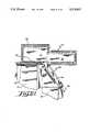
- FIG. 11(a)is a front view of a case for protecting the fluid delivery system of the present invention.
- FIGS. 11(b) and 11(c)are side views of the case of FIG. 11(a);
- FIG. 11(d)is top view of the case of FIG. 11(a);
- FIG. 12is perspective view of the case showing a preferred embodiment of the cover thereof in its open position.
- FIG. 13is a perspective view of the case of the present invention as described in FIGS. 11(c-d), with an alternative opening and closing design.
- an embodiment of a support device made in accordance with the principles of the present inventionreferred to generally by the reference numeral 10, is provided for convenient support of a standard (non-ambulatory type) fluid set and an infusion pump of a fluid delivery system for ambulatory use.
- the support device 10includes a generally rectangular rigid body 11 formed of rigid polymeric material or other lightweight material such as wood, metal alloy, etc.
- the body 11is adapted to receive and retain a fluid delivery set and infusion pump of a fluid delivery system.
- the body 11forms a pump compartment 12 adapted to receive a standard infusion pump 30 (as shown in FIG. 5(a), a container compartment 13 adapted to partially receive a container from a standard fluid set 16 (as shown for example in FIG. 5(a), a tube channel 14 adapted to receive the tube of a standard fluid set, and a valve compartment 15 adapted to receive a pinch valve located on the tube of the fluid set.
- the support device 10also includes a plurality of fastening elements which are adapted for use in securing the fluid delivery system to the body 11 during use. These elements include a lid clamp 17 which is permanently affixed to a lid clamp extension 18 of the body 11, a securing strap 19 which is secured to the body 11, a saddle bracket 21 which is secured in a flush mount position in the bottom of container compartment 13, and a pump locking mechanism 25 (best shown in FIG. 2 and FIG. 8(b)) formed as a part of the base 23 of the body 11.
- the body 11is also integrally formed with an elevated section 22 which, in cooperation with a similarly elevated section 26, forms part of the tube channel 14. Elevated section 22 also forms pump compartment 12.
- an extendable leg 20may be located in elevated section 22 so as to be flush therewith when the leg is in its retracted position, and to be extendable to a position perpendicular therewith and parallel to base 23 in its extended position.
- Leg 20may also have an identical counterpart on the back surface 45 of the body 11 (as best seen in FIGS. 2 and 3).
- the body 11is preferably formed by a vacuum forming process well known in the prior art which includes vacuum forming a front surface 39 separate and apart from the back surface 45 and then permanently interconnecting the surfaces to complete the formation of the rigid body 11 in a well known manner.
- a reaction injection or other injection or other injection molding technologymay be used.
- the pump compartment 12is formed of a generally C-shaped cavity having an upper and lower U-shaped channel 27 and 28, respectively, which are sized to receive a pump 30 in a sliding relationship (as shown in FIG. 5(a).
- U-shaped channels 27 and 28are designed to allow the pump 30 to slide therein until it abuts with abutment surface 29.
- the pump 30is preferably a peristaltic-type roller pump which includes a hinged receiving arm 31 for receiving the tubing of a fluid set 16 (as shown in FIG. 5(a) in a manner as will be described momentarily.
- the lower U-shaped channel 28is formed contiguously with the base 23 of the body 11 and includes the pump locking mechanism 25.
- the pump locking mechanism 25includes an upwardly extending locking pin 32 integrally formed with a lever arm 33 which in turn is connected to base 23 at an end 34 thereof. It is intended that the arm 33 be somewhat flexible and may be a separate component affixed to the base 23 or may be integrally molded therewith.
- the opposite end 35 of the lever arm, adjacent lock pin 32includes a release tab 35 which can be accessed through base opening 36 by a users finger in order to move the lock pin 32 into and out of locking position.
- a stop member 106is positioned to engage with release tube 35 when the lock pin 32 is moved out of locking position in order to prevent over extension of the locking mechanism 25.
- the pump 30, on bottom surface 37 thereofincludes a detent 38 which is sized and positioned so as to allow lock pin 32 to snap thereinto when pump 30 is properly positioned within the pump compartment 12. Positioning of the pump 30 within pump compartment 12 is accomplished by sliding the top and bottom of pump 30 into the upper and lower U-shaped channels 27 and 28, respectively. While the pump 30 is moving into the pump compartment 12, the bottom surface 37 thereof initially pushes lock pin 32 in a downward direction until the detent 38 becomes positioned thereover, after which the locking pin 32 snaps into position into the detent 38. The locking pin 32 then holds the pump within the pump compartment 12 until such time as the user pulls release tab 35 downwardly to withdraw lock pin 32 from the detent 38 and slides the pump 30 out of the pump compartment 12.
- the container compartment 13is located generally centrally within the front surface 39 of the body 11.
- Container compartment 13forms a generally rectangular recess within body 11 and is specifically sized to receive at least a portion of a fluid container of a fluid delivery set 16 in a manner as will be described momentarily.
- Located below container compartment 13are the elevated sections 22 and 26 of the body 11 which are oriented to form a tube path 40 for passing a tube from a container placed in container compartment 13 to the entrance 41 of the tube channel 14.
- the tube channel 14 of the support device 10extends around approximately two thirds of the circumference of the body 11.
- the tube channel 14is generally U-shaped in cross-section and includes a base 42, a front wall 43, and a back wall 44.
- the tube channel 14is essentially a channel between the front and back surfaces 39 and 45, respectively.
- the channel 14extends from entrance opening 41 across the top and partially down the opposite side of body 11 to exit opening 46. Slightly above exit opening 46 the channel 14 is interrupted by a pinch clamp compartment 15 which is sized to receive a standard type pinch clamp commonly attached to the tubing of a fluid delivery set 16.
- the pinch clamp compartment 15is formed by a cut out section of body 11 which is sufficiently large to allow a pinch clamp 99 (see FIG. 5(a)) to rest therein when the tubing to which it is attached is located in the tube channel 14 in a manner as will be demonstrated below.
- the channel 14is designed to allow accommodation of the tubing of the fluid set 16 even though slight variations in length thereof may occur. This is because the channel 14 is of sufficient depth (d) to allow some "snaking" of the tube within the channel 14 if necessary to accommodate its entire length.
- the channel 14is also designed to retain the tubing therein once place, even though some "snaking" may occur.
- the channelis generally of a width (w) which is slightly larger than the diameter of the tube.
- the width (R)is restricted to a dimension less than the diameter of the tube.
- the restrictionis in the form of a lip 113 which ensures that the tubing stays with the channel. Without the pressure of the lip 113, the tube would have the mechanical inclination to bow outwardly and at least partially escape the channel at various locations around the body 11.
- the tubeDue to the restricted width (R) of the channel 14 caused by the lip 113, the tube becomes resiliently deformed into an oval cross-sectional shape while passing into the channel 14. Once the tube is entirely in place within the channel 14, it will return to its circular cross-sectional shape and the tube will thereafter be retained within the channel 14 until forcibly withdrawn therefrom.
- the forward sloping section 24 of the body 11causes the exit opening 46 of the tube channel 14 to be positioned somewhat centrally over the pump compartment 12. This is advantageous in that it allows the tubing of the fluid delivery set to exit channel 14 at exit opening 46 in the proper position for reception into the hinged pump arm 31 of the pump 30 in the manner as also will be demonstrated below.
- the support device 10 of the present inventionis adapted to be able to receive and secure several different types of containers commonly used with standard fluid delivery sets 16.
- container compartment 13is recessed below front surface 39 of body 11, and shaped to receive a portion of a rigid blow molded type plastic bottle 47.
- the body 11can include a lid clamp extension 18 on its front surface 39, which extends above the container compartment 13 and which includes a lid clamp 17 oriented to receive the lid 48 of a soft flexible bag 49.
- the lid clamp 17operates to secure the lid 48 of bag 49 in its proper position to allow the bag 49 to be properly located within container compartment 13. Also, and more importantly, the lid clamp 17 operates to prevent inadvertent bursting open of the lid 48 during use, such as may occur due to an exterior pressure being inadvertently applied to the bag 49.
- the lid clamp 17includes a inner clamp jaw 50 permanently attached to the lid clamp extension 18.
- the inner jaw 50is permanently attached through hinge 51 to an outer clamp jaw 52.
- a fastenersuch as a strap 107 including the pile portion 53 of a hook and pile type fastener may be attached to jaw 52, with the hook portion 54 of the fastener attached to jaw 50.
- the strap 107allows the clamp 17 to be securely fixed in a closed position.
- the jaws 50 and 52 of the clamp 17When in the closed position, the jaws 50 and 52 of the clamp 17 form a circular opening for receiving the mouth and lid 48 of the bag 49.
- the circular opening of the inner clamp jaw 50forms an inner lip channel 55
- the outer clamp jaw 52forms an outer lip channel 56 which will receive the circumferential edges of mouth and lid 48 of the bag 49.
- the lid 48generally includes an opening tab 57 thereon, the outer clamp jaw 52 is formed with a tab opening 58 through which the tab 57 can extend when the clamp 17 is closed about the lid 48.
- the lid clamp 17can be positioned above container compartment 13 a sufficient distance to allow the accommodation of the desired size of bag 49.
- the lid clamp extension 18can be of a sufficient length to allow sufficient room in container compartment 13 to accept a bag 49 of the standard 1000 ml. volume.
- the lid clamp extension 18may be somewhat shorter to allow the container compartment 13 to accept and properly position a bag 49 of standard 600 ml. volume.
- a burette-type container 59commonly used with standard fluid delivery sets 16, can be partially fitted within container compartment 13 and held in place with the aid of strap 19 and saddle bracket 21.
- the saddle bracket 21is located within compartment 13 and flush mounted with the bottom 60 thereof.
- the bracket 21includes a cross bar 61 and a pair of bracket arms 62 which extend perpendicularly therefrom and which are spaced apart from each other a distance slightly greater than the diameter of the burette 59.
- the bracket 21can remain flush mounted within bottom 60 of the container compartment when not in use, and can be rotated 90 degrees to cause the bracket arm 62 to extend perpendicularly from bottom 60 of the container compartment 13 when used with the burette 59.
- the saddle bracket 21can be used in a similar manner to support the mouth and lid 115 of the rigid plastic bottle 47 when used with the device 10 as will be explained below.
- saddle bracket 21rests within a cavity 63 in the bottom 60 of the container compartment 13.
- the cross bar 61extends beyond the bracket arms 62 to pass into bracket arm mounting holes 64.
- the saddle bracket 21can be lifted into its upright position by pulling bracket arm 62 upwardly from the cavity 63. This is most easily accomplished by inserting a finger into the cavity extension 108 and leveraging the arm 62 slightly out of the cavity 63. Bracket arm 62 can then be gripped from the container compartment 13 and rotated until they are in a perpendicular position relative to bottom 60.
- the cross bar 61 and the bracket arm mounting hole 64may be formed into square cross-sectional shapes with a large tolerance between the size of the mounting holes 64 and the cross bar 61 to allow a slight resilient deformation of the mounting hole 64 as the cross bar is rotated therein.
- Such a designcauses the arms 62 of the bracket 21 to be biased into a flush position with bottom 60 of the container compartment 13 until they are rotated a full ninety degrees at which point the cross bar 61 is again properly oriented within mounting hole 64.
- Such a mounting designis commonly referred to as a "snap up” and/or “snap down” type mounting.
- a strap 19is located on the front surface 39 of the body 11 in a position adjacent the container compartment 13 and is of sufficient length to cross over a container placed in container compartment 13 and be attached to the upper U-shaped channel 27 of the pump compartment 12 in a convenient manner such as by hook and pile fastener 65 and 66, respectively.
- the support device 10is adapted to be used with a pump 30 and fluid delivery set 16 in a variety of environments.
- body 11 of the support device 10includes a mounting hole 109 to allow the device 10 to be attached to a standard infusion pole for use with bed ridden or ambulatory patients.
- the device 10may be placed on its base 23 on a level surface such as a table or the like without the need for any other mounting aid.
- the elevated section 22 of the front surface 39, and a generally opposing area of the back surface 45may include support legs 20 flush mounted in recesses 67. The legs 20 can be rotated to an open position parallel with the surface 39 and flush with base 23.
- the leg 20extends away from the front surface 39 of the body 11 to substantially increase the stability of the support device 10 when placed on a level surface.
- another leg 20can extend away from the back surface 45 in an identical manner.
- Each leg 20rotates between its extended and retracted positions by means of hinges 110.
- a locking mechanism 111adjacent at least one hinge 110 on each leg 20 is a locking mechanism 111 which will flex into interfering position with the front surface 39 (or back surface 45) when the leg 20 is fully extended and will prevent inadvertent retraction of the leg 20.
- the locking mechanism 111can be pushed laterally by the user to cause it to resiliently bend away interference with the surface 39 (or 45) and the leg 20 is simultaneously rotated into the recess 67 to its retracted position flush with surface 39 (or 45).
- a case 68may be utilized to store the device 10, along with the pump 30 and fluid delivery set 16 attached thereto, in order to allow complete and convenient ambulatory use thereof.
- the case 68is formed generally to conform to the exterior shape of the support device 10 and includes semi-rigid foam lined walls 69 and cover 70.
- the front 71 of the case 68includes a visual access opening 72, covered with a clear plastic panel 73, which allows visual access to the container when mounted to the support device 10 for use.
- Front 71 of the case 68also includes a control panel opening 74 which allows visual and physical access to the control panel 75 and display 76 of the pump 30.
- the opening 72is covered by a flap 77 which is sized so as to cover the entire opening 72 in a protective manner.
- the flap 77can include an opening tab 78 and a fastening means such as hook and pile fasteners 79 and 80, respectively.
- Control panel opening 74also includes a flap 81 sized to completely cover the opening 74 to protect the pump 30. Flap 81 may also include an opening tab 82 and hook and pile type fasteners 83 and 84, respectively. Further, as best shown in FIG. 11(c), flap 81 may also include a semi-rigid protection panel 85 which will supply added protection against accidental control panel activation or damage to the pump 30 due to an inadvertent blow to the case 68. As best shown in FIGS. 11(b and c), the case 68 can include a carrying strap 86 for allowing the case to be carried on the shoulder, back or around the waist of the patient while ambulatory.
- the casealso includes a tube outlet 87 to allow tubing 103 (see FIG. 5(a)) exiting the pump to pass outside of the case 68 to be attached to the patient.
- the cover 70 of the case 68can be formed to accommodate the irregularly shaped case opening 88.
- the cover 70may include hooks 89 around the entire inner circumference thereof which can fasten to piles 90 located around the outer perimeter of the top of the case 68.
- the cover 70may also include a first portion 91 sized to cover a first portion 92 of the case opening 88 while a second portion 93 of the cover may be adapted to conform to a second portion 94 of the case opening 88 which is oriented at an angle relative to the first portion 92.
- the entire cover 70may be attached to the case 68 such as by the stitching 95 to secure a single flap 96 of the cover 70 to the back surface 97 of the case 68.
- the flaps 77 and 81may be stitched or otherwise permanently attached at the upper most portions thereof, and carrying strap 86 may be riveted or otherwise permanently secured to the case 68.
- FIG. 13An alternative embodiment of the case 68 is shown in FIG. 13.
- the case 68'is substantially similar to case 68 except that there is no cover 70.
- the case 68'is formed substantially in two halves which are fixed together at a single common side thereof.
- the case 68'thus opens and closes in a "clam-shell” fashion.
- the case 68'may be secured in its closed position in any well known manner, preferably by a zipper 112 which extends around the majority of the circumference of the case 68'.
- the fluid delivery setincludes a container such as the plastic bottle 47, with a standard length of tubing 98 extending therefrom which is in fluid communication with the bottom thereof.
- the tubing 98includes a pinch valve 99 thereon and a drip chamber 100 attached at the end thereof.
- the opposite end of the drip chamber 100is attached to an extensible relatively thin-walled pump roller tube 101 which especially adapted for use with the pump 30.
- An extension ring 102is attached to pump tubing 101 and functions to insure that the pump tubing 101 is properly stretched over the rollers (not shown) of the pump 30. Beyond extension ring 102 is an infusion tube 103 which is intended to be attached to the patient.
- FIGS. 5(a-d)the method attachment of a fluid delivery set 16 including the rigid bottle 47, and a pump 30 to the support device 10 of the present invention is described as follows.
- the pump 30is inserted into pump compartment 12 until it is locked in position by pump locking mechanism 25.
- the saddle bracket 21is lifted to its "pop-up" position and the bottle 47 is inserted into the container compartment 13 until tubing 98 thereof can extend into the tube path 40.
- the bracket 21secures the mouth and lid 115 of the bottle 37 against lateral movement.
- the strapis then secured over bottle 37 to prevent its escape from the compartment 13.
- the tube 98is then grasped and forced into entrance 41 of tube channel 14 and drawn the entire length of channel 14 until pinch valve 99 is reached.
- pinch valve 99is adjusted along tubing 98 until it is oriented properly to be received in pinch valve compartment 15. Tubing 98 is then extended through the remainder of tubing channel 14 and allowed to extend beyond exit 46.
- the drip chamber 100is inserted into the hinged arm 31 of the pump 30 and pump tubing 101 is passed around the pump rotors until the retention ring 102 is properly positioned in a slot within the arm 31 in such a manner as will cause the tube 101 to be stretched over the rollers of the pump 30 when the arm 31 is moved to its closed position.
- the pump arm 31is then rotated into its closed and operating position and the infusion tube 103 extends away from the pump arm toward the patient.
- the support devicemay be placed on an infusion pole by inserting a hook thereof (not shown) through hole 109.
- legs 20may be extended and the support device 10 may be rested on its base 23 on a horizontal surface such as a table or the like.
- the support devicemay be inserted into the case 68 or 68' with the infusion tube 103 extending out of the case by passing it through the tubing outlet opening 87.
- a fluid delivery set including a flexible bag 49is attached to the support device 10 in an manner similar to that described in FIGS. 5(a-d) with respect to the rigid bottle type fluid infusion set 16, except that the lid 48 of the flexible bag 49 is inserted into the lid clamp 17 and securely clamped in place.
- a fluid infusion set 16 including a burette type containercan be positioned in the support device 10 in a manner similar to that described with respect to the rigid bottle in FIGS. 5(a-d), except that the saddle bracket 21 is first rotated to its "snap up" position and the burette 59 is placed between the bracket arms 62.
- the strap 19may be used to secure the container and the container compartment 13.
- other standard fluid sets 16, such as spike sets, etc.can be similarly used with the support device 10 of the present invention.
Landscapes
- Health & Medical Sciences (AREA)
- Vascular Medicine (AREA)
- Engineering & Computer Science (AREA)
- Anesthesiology (AREA)
- Biomedical Technology (AREA)
- Heart & Thoracic Surgery (AREA)
- Hematology (AREA)
- Life Sciences & Earth Sciences (AREA)
- Animal Behavior & Ethology (AREA)
- General Health & Medical Sciences (AREA)
- Public Health (AREA)
- Veterinary Medicine (AREA)
- Infusion, Injection, And Reservoir Apparatuses (AREA)
Abstract
Description
Claims (27)
Priority Applications (16)
| Application Number | Priority Date | Filing Date | Title |
|---|---|---|---|
| IL101445AIL101445A (en) | 1991-04-03 | 1991-04-01 | Ambulatory fluid delivery system |
| US07/679,886US5170817A (en) | 1991-04-03 | 1991-04-03 | Support device for fluid delivery system and case therefore |
| US07/818,194US5168892A (en) | 1991-04-03 | 1992-01-08 | Adjustable carrying case for a fluid delivery system |
| US07/819,300US5236004A (en) | 1991-04-03 | 1992-01-09 | Ambulatory support device for a fluid delivery system |
| DK92910842.1TDK0578775T3 (en) | 1991-04-03 | 1992-03-31 | Fluid delivery system for ambulatories |
| CA002107370ACA2107370A1 (en) | 1991-04-03 | 1992-03-31 | Ambulatory fluid delivery system |
| AU17707/92AAU664033B2 (en) | 1991-04-03 | 1992-03-31 | Ambulatory fluid delivery system |
| PCT/US1992/002619WO1992017226A2 (en) | 1991-04-03 | 1992-03-31 | Ambulatory fluid delivery system |
| DE69205159TDE69205159T2 (en) | 1991-04-03 | 1992-03-31 | MOBILE LIQUID DISPENSING SYSTEM. |
| AT92910842TATE128367T1 (en) | 1991-04-03 | 1992-03-31 | MOVABLE LIQUID DISPENSING SYSTEM. |
| JP4510009AJPH07508181A (en) | 1991-04-03 | 1992-03-31 | portable fluid supply system |
| EP92910842AEP0578775B1 (en) | 1991-04-03 | 1992-03-31 | Ambulatory fluid delivery system |
| IL101445AIL101445A0 (en) | 1991-04-03 | 1992-04-01 | Ambulatory fluid delivery system |
| IE921046AIE68320B1 (en) | 1991-04-03 | 1992-04-02 | Ambulatory fluid delivery system |
| MX9201541AMX9201541A (en) | 1991-04-03 | 1992-04-03 | SYSTEM FOR THE SUPPLY OF A FLUID AND SUPPORT DEVICE FOR THE SAME. |
| AU30405/95AAU676972B2 (en) | 1991-04-03 | 1995-09-01 | Ambulatory fluid delivery system |
Applications Claiming Priority (1)
| Application Number | Priority Date | Filing Date | Title |
|---|---|---|---|
| US07/679,886US5170817A (en) | 1991-04-03 | 1991-04-03 | Support device for fluid delivery system and case therefore |
Related Child Applications (2)
| Application Number | Title | Priority Date | Filing Date |
|---|---|---|---|
| US07/818,194Continuation-In-PartUS5168892A (en) | 1991-04-03 | 1992-01-08 | Adjustable carrying case for a fluid delivery system |
| US07/819,300Continuation-In-PartUS5236004A (en) | 1991-04-03 | 1992-01-09 | Ambulatory support device for a fluid delivery system |
Publications (1)
| Publication Number | Publication Date |
|---|---|
| US5170817Atrue US5170817A (en) | 1992-12-15 |
Family
ID=24728789
Family Applications (1)
| Application Number | Title | Priority Date | Filing Date |
|---|---|---|---|
| US07/679,886Expired - LifetimeUS5170817A (en) | 1991-04-03 | 1991-04-03 | Support device for fluid delivery system and case therefore |
Country Status (1)
| Country | Link |
|---|---|
| US (1) | US5170817A (en) |
Cited By (25)
| Publication number | Priority date | Publication date | Assignee | Title |
|---|---|---|---|---|
| US5370622A (en)* | 1994-04-28 | 1994-12-06 | Minimed Inc. | Proctective case for a medication infusion pump |
| US5429602A (en)* | 1992-04-29 | 1995-07-04 | Hauser; Jean-Luc | Programmable portable infusion pump system |
| US5478211A (en)* | 1994-03-09 | 1995-12-26 | Baxter International Inc. | Ambulatory infusion pump |
| US5782611A (en)* | 1994-10-06 | 1998-07-21 | Neftel; Frederic | Portable pump assembly |
| US5873853A (en)* | 1995-05-23 | 1999-02-23 | Baxter International Inc. | Portable pump apparatus for continuous ambulatory peritoneal dialysis and a method for providing same |
| WO2000016825A3 (en)* | 1998-09-18 | 2000-08-24 | Baxter Int | Support devices for surgical systems |
| US20050224534A1 (en)* | 2003-03-18 | 2005-10-13 | Hudson Joseph A | Portable enteral feeding apparatus |
| US20090247993A1 (en)* | 2008-03-27 | 2009-10-01 | Kirschenman Mark B | Robotic catheter system |
| US20090247944A1 (en)* | 2008-03-27 | 2009-10-01 | Kirschenman Mark B | Robotic catheter rotatable device cartridge |
| US20090248042A1 (en)* | 2008-03-27 | 2009-10-01 | Kirschenman Mark B | Model catheter input device |
| US20090247943A1 (en)* | 2008-03-27 | 2009-10-01 | Kirschenman Mark B | Robotic catheter device cartridge |
| US20090247942A1 (en)* | 2008-03-27 | 2009-10-01 | Kirschenman Mark B | Robotic catheter manipulator assembly |
| USD622377S1 (en) | 2008-12-05 | 2010-08-24 | Mark Jackson | Support stand for a feeding tube |
| US20100256558A1 (en)* | 2008-03-27 | 2010-10-07 | Olson Eric S | Robotic catheter system |
| US20110015569A1 (en)* | 2008-03-27 | 2011-01-20 | Kirschenman Mark B | Robotic catheter system input device |
| US20110021984A1 (en)* | 2008-03-27 | 2011-01-27 | Kirschenman Mark B | Robotic catheter system with dynamic response |
| US20110144806A1 (en)* | 2008-03-27 | 2011-06-16 | St. Jude Medical, Atrial Fibrillation Division, Inc. | Intelligent input device controller for a robotic catheter system |
| US20110238010A1 (en)* | 2008-12-31 | 2011-09-29 | Kirschenman Mark B | Robotic catheter system input device |
| US9330497B2 (en) | 2011-08-12 | 2016-05-03 | St. Jude Medical, Atrial Fibrillation Division, Inc. | User interface devices for electrophysiology lab diagnostic and therapeutic equipment |
| US9439736B2 (en) | 2009-07-22 | 2016-09-13 | St. Jude Medical, Atrial Fibrillation Division, Inc. | System and method for controlling a remote medical device guidance system in three-dimensions using gestures |
| US9888973B2 (en) | 2010-03-31 | 2018-02-13 | St. Jude Medical, Atrial Fibrillation Division, Inc. | Intuitive user interface control for remote catheter navigation and 3D mapping and visualization systems |
| USD846756S1 (en)* | 2016-12-01 | 2019-04-23 | Smiths Medical Asd, Inc. | Pole clamp for medical device |
| USD871610S1 (en) | 2018-04-18 | 2019-12-31 | Smiths Medical Asd, Inc. | Pole clamp for medical device |
| US20200179224A1 (en)* | 2017-05-16 | 2020-06-11 | Fresenius Medical Care Deutschland Gmbh | Peritoneal dialysis system |
| US11497579B2 (en) | 2017-04-19 | 2022-11-15 | Smiths Medical Asd, Inc. | Pole clamp assembly for medical devices |
Citations (20)
| Publication number | Priority date | Publication date | Assignee | Title |
|---|---|---|---|---|
| US3228474A (en)* | 1961-08-11 | 1966-01-11 | Jr Charles K Huthsing | Fire extinguisher |
| US3880188A (en)* | 1973-11-15 | 1975-04-29 | Whirlpool Co | Hose retractor for an appliance |
| US3972649A (en)* | 1974-10-30 | 1976-08-03 | Werner Jutte | Method of peristaltic pumping and device for working by such method |
| US4207889A (en)* | 1978-10-27 | 1980-06-17 | The United States Of America As Represented By The Secretary Of The Air Force | Injection system for suspension and solutions |
| US4311050A (en)* | 1979-08-27 | 1982-01-19 | Bessman Samuel P | Reservoir for medicaments |
| US4397639A (en)* | 1980-04-24 | 1983-08-09 | Ferring Arzneimittel Gmbh | Device for the intermittent pulsatory application of fluid medicaments |
| US4416595A (en)* | 1981-03-13 | 1983-11-22 | Baxter Travenol Laboratories, Inc. | Miniature rotary infusion pump with slide latch and detachable power source |
| US4479761A (en)* | 1982-12-28 | 1984-10-30 | Baxter Travenol Laboratories, Inc. | Actuator apparatus for a prepackaged fluid processing module having pump and valve elements operable in response to externally applied pressures |
| US4507112A (en)* | 1982-04-05 | 1985-03-26 | Ipco Corporation | Infusion monitor |
| US4513796A (en)* | 1982-06-24 | 1985-04-30 | Baxter Travenol Laboratories, Inc. | High speed bulk compounder |
| US4545783A (en)* | 1983-07-11 | 1985-10-08 | Warner-Lambert Company | Rigid medical solution container |
| WO1986001413A1 (en)* | 1984-08-29 | 1986-03-13 | Stanley Alexander Schweitzer | Apparatus for feeding metered amount of liquid |
| US4657486A (en)* | 1984-01-13 | 1987-04-14 | Stempfle Julius E | Portable infusion device |
| US4688595A (en)* | 1986-02-20 | 1987-08-25 | Sherwood Medical Company | Enteral nutrition delivery system |
| US4699613A (en)* | 1985-12-23 | 1987-10-13 | Donawick William J | Apparatus for the gravitational administration of fluids and drugs to large animals |
| US4720636A (en)* | 1984-08-06 | 1988-01-19 | Abbott Laboratories | Drop detecting system which operates under different ambient light conditions |
| US4722734A (en)* | 1984-04-14 | 1988-02-02 | Ferring Biotechnik, Gmbh | Device for the intermittent pulsatory application of liquid pharmaceuticals |
| US4832584A (en)* | 1988-01-15 | 1989-05-23 | Corpak, Inc. | Rotor for peristaltic pump |
| US5011378A (en)* | 1988-07-08 | 1991-04-30 | I-Flow Corporation | Pump tube mount and cartridge for infusion pump |
| US5057081A (en)* | 1990-06-15 | 1991-10-15 | Sherwood Medical Company | Peristaltic infusion device |
- 1991
- 1991-04-03USUS07/679,886patent/US5170817A/ennot_activeExpired - Lifetime
Patent Citations (20)
| Publication number | Priority date | Publication date | Assignee | Title |
|---|---|---|---|---|
| US3228474A (en)* | 1961-08-11 | 1966-01-11 | Jr Charles K Huthsing | Fire extinguisher |
| US3880188A (en)* | 1973-11-15 | 1975-04-29 | Whirlpool Co | Hose retractor for an appliance |
| US3972649A (en)* | 1974-10-30 | 1976-08-03 | Werner Jutte | Method of peristaltic pumping and device for working by such method |
| US4207889A (en)* | 1978-10-27 | 1980-06-17 | The United States Of America As Represented By The Secretary Of The Air Force | Injection system for suspension and solutions |
| US4311050A (en)* | 1979-08-27 | 1982-01-19 | Bessman Samuel P | Reservoir for medicaments |
| US4397639A (en)* | 1980-04-24 | 1983-08-09 | Ferring Arzneimittel Gmbh | Device for the intermittent pulsatory application of fluid medicaments |
| US4416595A (en)* | 1981-03-13 | 1983-11-22 | Baxter Travenol Laboratories, Inc. | Miniature rotary infusion pump with slide latch and detachable power source |
| US4507112A (en)* | 1982-04-05 | 1985-03-26 | Ipco Corporation | Infusion monitor |
| US4513796A (en)* | 1982-06-24 | 1985-04-30 | Baxter Travenol Laboratories, Inc. | High speed bulk compounder |
| US4479761A (en)* | 1982-12-28 | 1984-10-30 | Baxter Travenol Laboratories, Inc. | Actuator apparatus for a prepackaged fluid processing module having pump and valve elements operable in response to externally applied pressures |
| US4545783A (en)* | 1983-07-11 | 1985-10-08 | Warner-Lambert Company | Rigid medical solution container |
| US4657486A (en)* | 1984-01-13 | 1987-04-14 | Stempfle Julius E | Portable infusion device |
| US4722734A (en)* | 1984-04-14 | 1988-02-02 | Ferring Biotechnik, Gmbh | Device for the intermittent pulsatory application of liquid pharmaceuticals |
| US4720636A (en)* | 1984-08-06 | 1988-01-19 | Abbott Laboratories | Drop detecting system which operates under different ambient light conditions |
| WO1986001413A1 (en)* | 1984-08-29 | 1986-03-13 | Stanley Alexander Schweitzer | Apparatus for feeding metered amount of liquid |
| US4699613A (en)* | 1985-12-23 | 1987-10-13 | Donawick William J | Apparatus for the gravitational administration of fluids and drugs to large animals |
| US4688595A (en)* | 1986-02-20 | 1987-08-25 | Sherwood Medical Company | Enteral nutrition delivery system |
| US4832584A (en)* | 1988-01-15 | 1989-05-23 | Corpak, Inc. | Rotor for peristaltic pump |
| US5011378A (en)* | 1988-07-08 | 1991-04-30 | I-Flow Corporation | Pump tube mount and cartridge for infusion pump |
| US5057081A (en)* | 1990-06-15 | 1991-10-15 | Sherwood Medical Company | Peristaltic infusion device |
Non-Patent Citations (5)
| Title |
|---|
| Fresenius AG, Frenta System for Continuous Tube Feeding, Instruction For Use, 1983, 13 pages.* |
| Fresenius AG, Frenta-System for Continuous Tube Feeding, Instruction For Use, 1983, 13 pages. |
| Ross Laboratories, Flexiflo Companion Enteral Nutrition Pump Operating Manual, Aug. 1987, pp. 1 16.* |
| Ross Laboratories, Flexiflo Companion Enteral Nutrition Pump Operating Manual, Aug. 1987, pp. 1-16. |
| Ross Laboratories, Introducing Flexiflo Companion Enteral Nutrition Pump, Feb. 1988, 2 pages.* |
Cited By (49)
| Publication number | Priority date | Publication date | Assignee | Title |
|---|---|---|---|---|
| US5429602A (en)* | 1992-04-29 | 1995-07-04 | Hauser; Jean-Luc | Programmable portable infusion pump system |
| US5478211A (en)* | 1994-03-09 | 1995-12-26 | Baxter International Inc. | Ambulatory infusion pump |
| US5370622A (en)* | 1994-04-28 | 1994-12-06 | Minimed Inc. | Proctective case for a medication infusion pump |
| US5782611A (en)* | 1994-10-06 | 1998-07-21 | Neftel; Frederic | Portable pump assembly |
| US5873853A (en)* | 1995-05-23 | 1999-02-23 | Baxter International Inc. | Portable pump apparatus for continuous ambulatory peritoneal dialysis and a method for providing same |
| US5984891A (en)* | 1995-05-23 | 1999-11-16 | Baxter International Inc. | Portable pump apparatus for continuous ambulatory peritoneal dialysis and a method for providing same |
| US6196992B1 (en) | 1995-05-23 | 2001-03-06 | Baxter International Inc. | Portable pump apparatus for continuous ambulatory peritoneal dialysis and a method for providing same |
| WO2000016825A3 (en)* | 1998-09-18 | 2000-08-24 | Baxter Int | Support devices for surgical systems |
| US6632189B1 (en) | 1998-09-18 | 2003-10-14 | Edwards Lifesciences Corporation | Support device for surgical systems |
| US20050224534A1 (en)* | 2003-03-18 | 2005-10-13 | Hudson Joseph A | Portable enteral feeding apparatus |
| US7282044B2 (en) | 2003-03-18 | 2007-10-16 | Sherwood Services Ag | Portable enteral feeding apparatus |
| US20080035694A1 (en)* | 2003-03-18 | 2008-02-14 | Sherwood Services Ag | Concealment device for a feeding device |
| US8317745B2 (en) | 2008-03-27 | 2012-11-27 | St. Jude Medical, Atrial Fibrillation Division, Inc. | Robotic catheter rotatable device cartridge |
| US9241768B2 (en) | 2008-03-27 | 2016-01-26 | St. Jude Medical, Atrial Fibrillation Division, Inc. | Intelligent input device controller for a robotic catheter system |
| US20090248042A1 (en)* | 2008-03-27 | 2009-10-01 | Kirschenman Mark B | Model catheter input device |
| US20090247943A1 (en)* | 2008-03-27 | 2009-10-01 | Kirschenman Mark B | Robotic catheter device cartridge |
| US20090247942A1 (en)* | 2008-03-27 | 2009-10-01 | Kirschenman Mark B | Robotic catheter manipulator assembly |
| WO2009120940A3 (en)* | 2008-03-27 | 2009-12-30 | St. Jude Medical, Atrial Fibrillation Division, Inc. | Robotic catheter system |
| US11717356B2 (en) | 2008-03-27 | 2023-08-08 | St. Jude Medical, Atrial Fibrillation Division, Inc. | System and method of automatic detection of obstructions for a robotic catheter system |
| US20100256558A1 (en)* | 2008-03-27 | 2010-10-07 | Olson Eric S | Robotic catheter system |
| US20110015569A1 (en)* | 2008-03-27 | 2011-01-20 | Kirschenman Mark B | Robotic catheter system input device |
| US20110021984A1 (en)* | 2008-03-27 | 2011-01-27 | Kirschenman Mark B | Robotic catheter system with dynamic response |
| US20110144806A1 (en)* | 2008-03-27 | 2011-06-16 | St. Jude Medical, Atrial Fibrillation Division, Inc. | Intelligent input device controller for a robotic catheter system |
| US10426557B2 (en) | 2008-03-27 | 2019-10-01 | St. Jude Medical, Atrial Fibrillation Division, Inc. | System and method of automatic detection of obstructions for a robotic catheter system |
| US20090247993A1 (en)* | 2008-03-27 | 2009-10-01 | Kirschenman Mark B | Robotic catheter system |
| US8317744B2 (en) | 2008-03-27 | 2012-11-27 | St. Jude Medical, Atrial Fibrillation Division, Inc. | Robotic catheter manipulator assembly |
| US8343096B2 (en) | 2008-03-27 | 2013-01-01 | St. Jude Medical, Atrial Fibrillation Division, Inc. | Robotic catheter system |
| US8641663B2 (en) | 2008-03-27 | 2014-02-04 | St. Jude Medical, Atrial Fibrillation Division, Inc. | Robotic catheter system input device |
| US8641664B2 (en) | 2008-03-27 | 2014-02-04 | St. Jude Medical, Atrial Fibrillation Division, Inc. | Robotic catheter system with dynamic response |
| US8684962B2 (en) | 2008-03-27 | 2014-04-01 | St. Jude Medical, Atrial Fibrillation Division, Inc. | Robotic catheter device cartridge |
| US9161817B2 (en) | 2008-03-27 | 2015-10-20 | St. Jude Medical, Atrial Fibrillation Division, Inc. | Robotic catheter system |
| US20090247944A1 (en)* | 2008-03-27 | 2009-10-01 | Kirschenman Mark B | Robotic catheter rotatable device cartridge |
| US9295527B2 (en) | 2008-03-27 | 2016-03-29 | St. Jude Medical, Atrial Fibrillation Division, Inc. | Robotic catheter system with dynamic response |
| US9301810B2 (en) | 2008-03-27 | 2016-04-05 | St. Jude Medical, Atrial Fibrillation Division, Inc. | System and method of automatic detection of obstructions for a robotic catheter system |
| US9314310B2 (en) | 2008-03-27 | 2016-04-19 | St. Jude Medical, Atrial Fibrillation Division, Inc. | Robotic catheter system input device |
| US9314594B2 (en) | 2008-03-27 | 2016-04-19 | St. Jude Medical, Atrial Fibrillation Division, Inc. | Robotic catheter manipulator assembly |
| US10231788B2 (en) | 2008-03-27 | 2019-03-19 | St. Jude Medical, Atrial Fibrillation Division, Inc. | Robotic catheter system |
| US9795447B2 (en) | 2008-03-27 | 2017-10-24 | St. Jude Medical, Atrial Fibrillation Division, Inc. | Robotic catheter device cartridge |
| USD622377S1 (en) | 2008-12-05 | 2010-08-24 | Mark Jackson | Support stand for a feeding tube |
| US20110238010A1 (en)* | 2008-12-31 | 2011-09-29 | Kirschenman Mark B | Robotic catheter system input device |
| US9439736B2 (en) | 2009-07-22 | 2016-09-13 | St. Jude Medical, Atrial Fibrillation Division, Inc. | System and method for controlling a remote medical device guidance system in three-dimensions using gestures |
| US10357322B2 (en) | 2009-07-22 | 2019-07-23 | St. Jude Medical, Atrial Fibrillation Division, Inc. | System and method for controlling a remote medical device guidance system in three-dimensions using gestures |
| US9888973B2 (en) | 2010-03-31 | 2018-02-13 | St. Jude Medical, Atrial Fibrillation Division, Inc. | Intuitive user interface control for remote catheter navigation and 3D mapping and visualization systems |
| US9330497B2 (en) | 2011-08-12 | 2016-05-03 | St. Jude Medical, Atrial Fibrillation Division, Inc. | User interface devices for electrophysiology lab diagnostic and therapeutic equipment |
| USD846756S1 (en)* | 2016-12-01 | 2019-04-23 | Smiths Medical Asd, Inc. | Pole clamp for medical device |
| US11497579B2 (en) | 2017-04-19 | 2022-11-15 | Smiths Medical Asd, Inc. | Pole clamp assembly for medical devices |
| US20200179224A1 (en)* | 2017-05-16 | 2020-06-11 | Fresenius Medical Care Deutschland Gmbh | Peritoneal dialysis system |
| US11857494B2 (en)* | 2017-05-16 | 2024-01-02 | Fresenius Medical Care Deutschland Gmbh | Peritoneal dialysis system |
| USD871610S1 (en) | 2018-04-18 | 2019-12-31 | Smiths Medical Asd, Inc. | Pole clamp for medical device |
Similar Documents
| Publication | Publication Date | Title |
|---|---|---|
| US5170817A (en) | Support device for fluid delivery system and case therefore | |
| US5342011A (en) | Fluid container attachment adaptor for an ambulatory fluid delivery system | |
| AU2003223283B2 (en) | Portable enteral feeding apparatus | |
| US6267564B1 (en) | Medical reservoir bag and system | |
| US4795441A (en) | Medication administration system | |
| US6142979A (en) | Pinch clip occluder system for infusion sets | |
| US5163909A (en) | Medical fluid delivery system | |
| US8545458B2 (en) | Pinch clamp assembly for an infusion cassette | |
| US5061248A (en) | Injection port safety shield | |
| US5222946A (en) | Compact intravenous fluid delivery system | |
| US6749591B1 (en) | Pinch clip occluder system for infusion sets | |
| US20070156091A1 (en) | Syringe holding system | |
| US5236004A (en) | Ambulatory support device for a fluid delivery system | |
| US5799846A (en) | Holder for a container which administers a feeding product to humans | |
| EP0578775B1 (en) | Ambulatory fluid delivery system | |
| EP3720521B1 (en) | Portable pump and container carrier | |
| US5168892A (en) | Adjustable carrying case for a fluid delivery system | |
| US20160287781A1 (en) | Compact Intravenous Pump and Medication Container Holder | |
| US6913150B1 (en) | Medical tool carrier | |
| US12102788B2 (en) | Portable IV bag suspension device | |
| US5478332A (en) | Intravenous injection cap support method | |
| US7850659B1 (en) | Fluid container holding device, fluid delivery system and method of use therefor | |
| AU676972B2 (en) | Ambulatory fluid delivery system | |
| WO2022115887A1 (en) | Intravenous infusion set and accessory therefor | |
| EP3436107B1 (en) | Enteral feeding bag and pump support |
Legal Events
| Date | Code | Title | Description |
|---|---|---|---|
| AS | Assignment | Owner name:SHERWOOD MEDICAL COMPANY, A CORP. OF DELAWARE, MIS Free format text:ASSIGNMENT OF ASSIGNORS INTEREST.;ASSIGNOR:SUNDERLAND, RICHARD A.;REEL/FRAME:005658/0975 Effective date:19910403 | |
| STCF | Information on status: patent grant | Free format text:PATENTED CASE | |
| FEPP | Fee payment procedure | Free format text:PAYOR NUMBER ASSIGNED (ORIGINAL EVENT CODE: ASPN); ENTITY STATUS OF PATENT OWNER: LARGE ENTITY | |
| FPAY | Fee payment | Year of fee payment:4 | |
| AS | Assignment | Owner name:SHERWOOD SERVICES AG, SWITZERLAND Free format text:ASSIGNMENT OF ASSIGNORS INTEREST;ASSIGNOR:TYCO GROUP S.A.R.L.;REEL/FRAME:010180/0294 Effective date:19990406 Owner name:TYCO GROUP S.A.R.L., LUXEMBOURG Free format text:ASSIGNMENT OF ASSIGNORS INTEREST;ASSIGNOR:SHERWOOD MEDICAL COMPANY;REEL/FRAME:010255/0446 Effective date:19990406 | |
| FPAY | Fee payment | Year of fee payment:8 | |
| FPAY | Fee payment | Year of fee payment:12 | |
| AS | Assignment | Owner name:COVIDIEN AG, SWITZERLAND Free format text:CHANGE OF NAME;ASSIGNOR:SHERWOOD SERVICES AG;REEL/FRAME:021371/0142 Effective date:20070309 |