US5169601A - Immunological agglutination detecting apparatus with separately controlled supplementary light sources - Google Patents
Immunological agglutination detecting apparatus with separately controlled supplementary light sourcesDownload PDFInfo
- Publication number
- US5169601A US5169601AUS07/516,101US51610190AUS5169601AUS 5169601 AUS5169601 AUS 5169601AUS 51610190 AUS51610190 AUS 51610190AUS 5169601 AUS5169601 AUS 5169601A
- Authority
- US
- United States
- Prior art keywords
- point light
- light sources
- agglutination
- row
- reaction vessels
- Prior art date
- Legal status (The legal status is an assumption and is not a legal conclusion. Google has not performed a legal analysis and makes no representation as to the accuracy of the status listed.)
- Expired - Fee Related
Links
Images


Classifications
- B—PERFORMING OPERATIONS; TRANSPORTING
- B01—PHYSICAL OR CHEMICAL PROCESSES OR APPARATUS IN GENERAL
- B01L—CHEMICAL OR PHYSICAL LABORATORY APPARATUS FOR GENERAL USE
- B01L3/00—Containers or dishes for laboratory use, e.g. laboratory glassware; Droppers
- B01L3/50—Containers for the purpose of retaining a material to be analysed, e.g. test tubes
- B01L3/508—Containers for the purpose of retaining a material to be analysed, e.g. test tubes rigid containers not provided for above
- B01L3/5085—Containers for the purpose of retaining a material to be analysed, e.g. test tubes rigid containers not provided for above for multiple samples, e.g. microtitration plates
- G—PHYSICS
- G01—MEASURING; TESTING
- G01N—INVESTIGATING OR ANALYSING MATERIALS BY DETERMINING THEIR CHEMICAL OR PHYSICAL PROPERTIES
- G01N21/00—Investigating or analysing materials by the use of optical means, i.e. using sub-millimetre waves, infrared, visible or ultraviolet light
- G01N21/75—Systems in which material is subjected to a chemical reaction, the progress or the result of the reaction being investigated
- G01N21/77—Systems in which material is subjected to a chemical reaction, the progress or the result of the reaction being investigated by observing the effect on a chemical indicator
- G01N21/82—Systems in which material is subjected to a chemical reaction, the progress or the result of the reaction being investigated by observing the effect on a chemical indicator producing a precipitate or turbidity
- G—PHYSICS
- G01—MEASURING; TESTING
- G01N—INVESTIGATING OR ANALYSING MATERIALS BY DETERMINING THEIR CHEMICAL OR PHYSICAL PROPERTIES
- G01N33/00—Investigating or analysing materials by specific methods not covered by groups G01N1/00 - G01N31/00
- G01N33/48—Biological material, e.g. blood, urine; Haemocytometers
- G01N33/50—Chemical analysis of biological material, e.g. blood, urine; Testing involving biospecific ligand binding methods; Immunological testing
- G01N33/53—Immunoassay; Biospecific binding assay; Materials therefor
- G01N33/5302—Apparatus specially adapted for immunological test procedures
- G—PHYSICS
- G01—MEASURING; TESTING
- G01N—INVESTIGATING OR ANALYSING MATERIALS BY DETERMINING THEIR CHEMICAL OR PHYSICAL PROPERTIES
- G01N21/00—Investigating or analysing materials by the use of optical means, i.e. using sub-millimetre waves, infrared, visible or ultraviolet light
- G01N21/75—Systems in which material is subjected to a chemical reaction, the progress or the result of the reaction being investigated
- G01N21/77—Systems in which material is subjected to a chemical reaction, the progress or the result of the reaction being investigated by observing the effect on a chemical indicator
- G01N21/82—Systems in which material is subjected to a chemical reaction, the progress or the result of the reaction being investigated by observing the effect on a chemical indicator producing a precipitate or turbidity
- G01N2021/825—Agglutination
Definitions
- This devicerelates to an immunological agglutination detecting apparatus, in particular, to an immunological agglutination detecting apparatus suitable to judge various blood types or group from the patterns of agglutination of blood cell particles or corpuscles and to detect antigens and antibodies.
- the immunological agglutination detection apparatus for detecting such blood cell corpuscle agglutination or condensation patternshas been studied and developed in many fields and practiced in the products.
- Japanese Utility Model publication No. 61-45479, Japanese Patent publication No. 61-8934, and Japanese Patent Laid-open No. 59-98708respectively disclose some immunological agglutination detection apparatuses of such kind.
- an image formed on the curved bottom face of a conical reaction vessel illuminated by a point light sourceis projected on a focus or image formation plane through a lens or an optical system.
- the conventional apparatushas a light receiving element placed at the image formation plane in order to receive an image scanned by a scanning mechanism and to convert the image to electrical signals progressively according to the intensity of light along the scanning direction.
- the light receiving elementhas an incident opening substantially identical to or smaller than the image of agglutination pattern formed at the center portion of the bottom face of the reaction vessel when it is non-agglutination, so that it is necessary to install a positioning mechanism for making the scanning light pass through the lowest portion (in which aggregations flock together) of the reaction vessel, resulting in a disadvantageously complicated structure.
- agglutination pattern obtained after being reactedchanges according to the particular kind of the immunological agglutination of an examination item, it is necessary to adjust the open area, shape and the like of the slit or incident opening of the light receiving element. This is troublesome.
- a collimator lens as an illumination lens for making the light beams projected from a fixed point light source to parallel light fluxis used, and the parallel light beam illuminates uniformly a microplate of the reaction vessel through a distribution plate (light diffusion plate) and the image on the conical bottom face of the reaction vessel is focussed on the light receiving face of the moving light receiving element.
- a distribution platelight diffusion plate
- the image on the conical bottom face of the reaction vesselis focussed on the light receiving face of the moving light receiving element.
- the conventional technologyhas such shortcomings as a low precision of the collimator lens and a too large structure of the illumination portion.
- the collimator lensis very expensive, resulting in a disadvantageously high price of the immunological agglutination detection apparatus.
- an agglutination examination plate unitcomprising a number of reaction vessels each having a slanted face of at least a part of the bottom face of the reaction vessel, the reaction vessels are arranged in the manner of a matrix (i.e. a grid) and formed on a base plate, a light source is placed at one side of the agglutination examination plate unit for projection therethrough, and a light receiving portion is situated at another side of the unit.
- a matrixi.e. a grid
- Respective images of the agglutination patterns formed on the bottom faces of the plurality of the reaction vessels due to illuminous light outputted from the luminesce or light emitting portionare focussed on the light receiving face of the light receiving elements constituting the light receiving portion by means of lens, and as a result an output signal is adapted to detect the agglutination patterns.
- the light emitting portion aboveis constructed by at least one point light source associated with each respective reaction vessel of the plurality of reaction vessels in any column or file or a transverse row, which point light source is opposed to a respective reaction vessel. According to the construction of the light emitting portion, subsidiary point light sources are arranged at both ends of the row of these primary light sources.
- the embodimentuses an ABO type judge or examination method of human blood, as an example, with respect to an immunological agglutination.
- ABO type judge or examination method of human bloodas an example, with respect to an immunological agglutination.
- the human beingare classified by the blood group of ABO type, it is possible to divide it to four groups of A, B, AB, and O types.
- O type red blood corpusclesare differed from that of A, B, and AB types red blood corpuscles, and AB type red blood corpuscles have the characters of respective A and B types red blood corpuscles additionally.
- two sample liquidsare prepared by pouring dilution solutions into respective red blood corpuscles of each blood group and then anti A blood sera (B type blood sera) and anti B blood sera (A type blood sera) of examination agents are dropped into respective sample liquids in order to judge the blood type of the subject.
- the blood type of the subjectwas A group and anti A blood sera was added to the blood, so as to carry out agglutination, and no condensation occurred.
- the blood of the subjectis not agglutinated by using anti A blood sera and agglutinated by anti B blood sera, it is B type.
- the blood type of the subjectis of AB type.
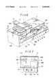
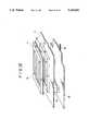
- FIG. 1is a construction view showing a major portion of an immunological agglutination detecting apparatus according to one embodiment of the present device
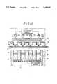
- FIG. 2shows the interior constructions of the light emitting portion and the light receiving portion shown in FIG. 1;
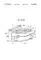
- FIG. 3is a perspective view of the light receiving unit shown in FIG. 1;
- FIG. 4is an explanation view showing an example of the arrangement of the light receiving unit shown in FIG. 1;
- FIG. 5is a view showing the whole structure of the microplate shown in FIG. 1;
- FIG. 6is an outline perspective view showing the whole structure of the embodiment shown in FIG. 1;
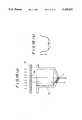
- FIG. 7is a sectional view taken along the line 7--7 of FIG. 6;
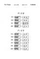
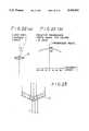
- FIG. 8is an explanation view of the relation between the light intensity control means and the light source shown in the embodiment of FIG. 1;
- FIG. 9is another explanation view of a relation similar to FIG. 8.
- FIG. 10is an explanation view of the operation of the embodiment shown in FIG. 1.
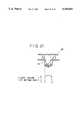
- FIG. 11shows examples of output patterns.
- FIG. 12is a concept view depicting the structure of a second embodiment of the invention.
- FIG. 13is a view of the horizontal plate shown in FIG. 12 and an explanation view depicting the positional relationship between the windows and the reaction vessels.
- FIG. 14is a concept view depicting the structure of a third embodiment of the invention.
- FIG. 15is a view of the horizontal plate and an explanation showing the positional relationship between the windows and the reaction vessels.
- FIG. 16is a concept view showing the structure of a fourth embodiment according to the invention.
- FIG. 17(a)is an explanatory view of the optical filter shown in FIG. 16, and FIG. 17(b) is an explanation of a light reduction effect of the optical filter of FIG. 17(a);
- FIG. 18(a)is an explanation of the condition in which the effect of the shadow generated by the light refraction phenomenon at the lowest point of the reaction vessel shown in FIG. 16 is restricted, and FIG. 18(b) shows the output of the primary CCD sensor when the reaction vessel is vacant;
- FIGS. 19(a)-(c)respectively show the output waves as the primary CCD sensor corresponding to the typical agglutination patterns obtained in the embodiment of FIG. 16.
- FIG. 20is a concept view showing the construction of a fifth embodiment according to the invention.
- FIGS. 21-23are explanations of functional aspects of the apparatus.
- FIGS. 1-10An embodiment of the invention will now be described with reference to FIGS. 1-10.
- the immunological agglutination detecting apparatus shown in FIG. 1includes a microplate 1 as an agglutination examination plate consisting of a number of reaction vessels 1a, respectively formed so as to have a conical shaped bottom plate as shown in FIG. 2, which reaction vessels arearranged in perpendicularly extending rows and columns which in effect define a matrix or grid configuration (see FIGS. 4, 5) on a transparent base plate 1b.
- a light emitting portion 4is placed on a side (upper side in FIG. 1) for projection through the microplate 1, and a light receiving unit 10 constructed as a light receiving portion is placed on the other side (lower side in FIG. 1).
- the light emitting portion 4includes light emitting diodes 2D, 2C, 2B, 2A,2D', 2C', 2B', 2A' defining primary point light sources, respectively placed opposed to reaction vessels 1 1i , 1 2i , 1 3i , 1 4i ,1 5j , 1 6j , 1 7j , 1 8j , forming any column (Column i, conveniently herein) and adjacent column (Column j, conveniently herein) of a number of reaction vessels arranged and formed on the microplate 1 inthe manner of a matrix.
- the light emitting portion 4has otherlight emitting diodes 2E, 2F, 2G, 2H defining supplemental point light sources, respectively arranged with respect to the end light emitting diodes 2A, 2D, 2A', 2D' so as to be disposed adjacent the opposite ends ofeach column of light emitting diodes 2D, 2C, 2B, 2A and 2D', 2C', 2B', 2A'.Between the light emitting portion 4 and the microplate 1, there are light distribution plates 31A, 31B, respectively arranged in parallel with the microplate 1 with a fixed gap or distance therebetween.
- the light receiving unit 10consists of a lens holder 5 provided with several convex lenses 6 arranged at regular intervals so as to oppose respective reaction vessels 1 and a primary CCD sensor 7 is held on the bottom of the lens holder 5 as shown in FIG. 2.
- the lens holder 5practically has an appearance as shown in FIG.3 and a plurality of holes (four in this embodiment) arranged at the same distance as that between the reaction vessels 1a, 1a adjacent to each other along the longitudinal direction of the holder 5.
- the convex lens 6are fixed.
- the primary CCD sensor 7is mounted at a fixed distancefrom the convex lens 6 equal to the focussing distance of the lens 6.
- the primary CCD sensor 7is parallel with the microplate 1.
- two light receiving units 10are used and respective units are arranged on the upper face of a moving plate16 (FIG. 7) which will be described below so as to make respective longitudinal parts of the light receiving units 10 overlap one another along the reaction vessels 1 1i , 1 2i , 1 3i , 1 4i , 1 5j , 1 6j , 1 7j , 1 8j of the Columns i and j.
- these light receiving units 10 and 10are connected by a connector 10A shown in FIGS. 3 and 4.
- these light receiving units 10are arranged as shown in FIG. 4 so as to make the four holes 5a, 5a. . . formed in each lens holder 5 at regular intervals identical to that between the reaction vessels adjacent to each other along the longitudinal direction of the holder 5 agree with the reaction vessels 1 1i , 1 2i , 1 3i , 1 4i , 1 5j , 1 6j , 1 7j , 1 8j .
- a number of reaction vessels 1aare arranged and formed in the microplate 1 in a matrix shape of eight (8) columns and twelve (12) rows (or files), and the microplate 1 with the reaction vessels 1a are mounted on a horizontal plate 11 (FIG. 6) made of transparent material, which horizontal plate 11 constitutes a part of the immunological agglutination detecting apparatus 20 as shown in FIG. 6.
- the immunological agglutination detecting apparatus 20 of the present devicehas an end support member or wall 12A and another end support member or wall 12B supporting the horizontal top plate 11 from the bottom.There is a reinforcement plate 12C extending between these support members 12A and 12B so as to stably connect them to each other.
- a guide shaft 13is installed on the immunological agglutination detecting apparatus of thepresent device along the longitudinal direction of the horizontal plate 11,extending in the space between and supported on the support members 12A and12B.
- another guide shaft 14 having a male thread engaged with a ball screw, which thread is formed along the whole length of the shaft,is rotatably supported on supports 12A and 12B and extends in parallel with the first guide shaft 13.
- Both shafts 13, 14have a box 15 mounted slidably and reciprocally thereon for movement along these shafts.
- the box 15has a hole 15a having a diameter almost identical to that of the shaft 13 and a hole 15b having a diameter substantially identical to that of the shaft 14.
- a moving plate 16 for mounting the light receiving unit 10 thereonis installed on the upper face of the box 15 so as to be parallel with the horizontal plate 11 and fixed thereto.
- Side support plates 18A and 18Bsupport an upper plate 17 at both ends of the upper plate. These support plates are attached to opposite sides of the moving plate 16 at a right angle.
- the light emitting diodes 2A, 2B . . .are fixed on the lower face of the upper plate 17.
- the light distribution plates 31A and 31Bare held integrally on the lower face of the upper plate 17.
- There is a LED driver circuit(see FIG. 12) for driving the light emitting diodes 2A, 2B . . . on the lower face of the upper plate 17.
- the LED driver circuitis constructed with electronic elements, such as IC and the like. According to the embodiment, the LED driver circuit also has light intensity controlmeans 22A-22D for adjusting each light emitting diode 2A, 2B . . . (see FIG. 8).
- the base plate 19On the upper face of the moving plate 16, there is a base plate 19 fixedly arranged in parallel with the moving plate 16.
- the base plate 19has a CCDdriver circuit (see FIG. 12) for driving the primary CCD sensor 7, which circuit is constructed with, for example, IC and the like and is mounted on the base plate 19.
- a motor 21 for rotating the shaft 14 through a gear set or mechanism(not shown ) is installed outside of the support member 12A.
- these plates 16 and 17are adapted to move reciprocally along the transverse rows of the reaction vessels 1a arrangedon the microplate.
- the primary CCD sensor 7employed in the embodiment in a general-purpose primary CCD sensor.
- the sensor 7has a light receiving face on which a plurality of photo electric converting elements of photo sensitivity are arranged in a line.
- the images of agglutination patterns formed on the bottom faces of the reaction vessels 1a, 1a . . .respectively are divided into five parts through a plurality of photoelectric converting elements and they are converted to electric signals through the elements according to the intensity of the light shone unto the sensor 7.
- the electric signalsare sent to a CPU (not shown) through an analog/digital converter (not shown) as known in the conventional system in order to judge the agglutination pattern of the test sample.
- respective light intensity control means 22A, 22B . . .are used to control volume or intensity of light.
- some reaction vessels 1 4i , 1 5j confrontingthe light emitting diodes 2A and 2D'are brighter than other reaction vessels because only these reaction vessels 1 4i , 1 5j are shone from three light emitting diodes, so that the light intensity of these light emitting diodes 2A and 2D' is lowered as is simultaneously the lightintensity of the light emitting diodes 2E and 2H as supplemental light sources.
- the light intensities of the light emitting diodes 2B, 2C, 2D, 2A', 2B', 2C'are accordingly adjusted making these intensities of thesame illumination and then the light emitting diodes 2F and 2G of the supplemental light sources are consequently controlled.
- the moving plate 16starts its motion and a positioning means (not shown) controls the CPU (not shown).
- a positioning means(not shown) controls the CPU (not shown).
- the lightreceiving units 10, 10 shown in FIGS. 1 and 4are moved to a position belowany column of the reaction vessels 1a formed in the microplate 1 and stopped at that position, the light beams from the light emitting diodes 2A, 2B . . . are shone on the microplate 1 through the light distribution plates 31A and 31B.
- respective images ofagglutination patterns formed on the bottom faces of the eight illuminated reaction vesselsfor example, vessels 1 1i , 1 2i , 1 3i , 1 4i , 1 5j , 1 6j , 1 7j , 1 8j .
- the images which are formed by shining light from the light emitting diodes 2A, 2B . . .are focussed on the primary CCD sensor 7 by the respective convex lens 6.
- Output signals from the primary CCD sensors 7, 7are sent to the CPU (not shown) through the analog/digital converter (not shown).
- the CPUcalculates the distance moved or position of the moving plate 16 from the feeding volume or revolution number of the motor in order to determine theparticular column of reaction vessels under examination, and then the agglutination pattern of the test sample in each reaction vessel is automatically judged.
- blood cell particlesare combined to each other or flocked together through blood sera in an agglutination phenomenon and are deposited uniformly on the conical bottomfaces of the reaction vessels 1a looking like snow.
- blood cell particlesare scattered or separated and descend to the conical bottom faces of the reaction vessels, and then these separated particles roll down along the slant walls to the lower central portion of the bottom face for deposit there.
- FIG. 10shows an enlarge view of the bottom face of the reaction vessel 1a.
- the radius of the bottom face of the reaction vessel 1ais 6 mm, the depth of the slanted portion is 1.5 mm, and the slant angle is 30 degree.
- FIG. 10shows the condition of the blood cell particles agglutinated or flockedtogether on the bottom face and deposited uniformly thereon.
- Such uniform deposition patterncan be attained in, for example, the ABO type blood group judging examination process, by adding anti A blood sera (B type blood sera) to A type subject (red blood corpuscles) suspension liquid letting them descend naturally or gravitationally.
- redblood corpusclesare uniformly deposited as described above, these corpuscles are adhered to each other through blood sera, so that there is substantially no rolling-down phenomenon of the red blood corpuscles alongthe slanted face of the reaction vessel and, on the contrary, they are deposited uniformly on the bottom face.
- light transmission volumeis the smallest at the point A, it increases gradually toward the peripheral portion C, and reaches its largest adjacent the peripheral portion C of the reaction vessel 1a. Resultantly, the output of the primary CCD sensor 7 changes according to the particular condition of the light transmission volume, so that the CPUjudges that it is of a uniform deposition pattern of the A type blood groupof the subject.
- FIG. 11depicts the images of agglutination patterns focussed on the light receiving face of the primary CCD sensor 7 and the output of the sensor 7 when such condensation patterns described above are generated.
- the leftmost diagramis an output corresponding to the pattern when no agglutination occurs
- the center diagramdepicts an output corresponding to the uniform deposit pattern
- the rightmost diagramis an output pattern of a vacant bottom face of an empty reaction vessel.
- two light receiving units 10are connected through their longitudinally overlapped parts by means of the connecting member 10A making a crank shape of them and accordingly the primary CCD sensors 7 as mounted to the bottom faces of the light receiving units 10 are arranged or positioned along the columns of the reaction vessels 1a so that it is possible to simultaneously detect several light images, at one time, of agglutinations in one column, which images are formed on the bottom faces of the reaction vessels 1a situated in a matrix shape on the microplate 1.
- the immunological agglutination detecting apparatus of the present deviceis constructed and functions as above, it is possible to shine light of uniform illumination to respective reaction vessels formed in theagglutination examination plate of the detecting apparatus, without any illuminous lens, as in prior devices. Consequently, it is possible to omitfrom the apparatus any illuminous lens, such as collimeter lens, without any decrease of credibility on the examination result.
- the optical systemcan be simplified and the apparatus can be miniaturized, reducing the manufacturing cost of the apparatus.
- FIGS. 12 and 13A second embodiment of the immunological agglutination detecting apparatus will be explained with reference to FIGS. 12 and 13. Corresponding parts of this embodiment are identified by the same reference numbers used to identify the parts of the first-described embodiment.
- the apparatus shown in FIG. 12has a microplate unit 1 of an agglutination examination plate consisting of a light transmittable base plate 1b and a plurality of reaction vessels, each designated 1a for convenience, arranged in a grid-like or matrix shape and having conical bottom faces.
- Arow of light emitting diodes, each designated 2A for convenience, of a light emitting meansis arranged at one side of the microplate 1 (at the upper side in FIG. 12), and the primary CCD sensor 7 of a light receiving means is arranged at the other side thereof (at the lower side in FIG. 12). Between the light emitting diodes 2A, 2A . . .
- the convex lenses 6are held in a lens holder 5 which has a plurality (fourin this embodiment) of holes 5a, 5a . . . separated at a regular distance identical to that between adjacent reaction vessels 1a, 1a and arranged along the longitudinal direction of the lens holder 5. Respective convex lenses 6 are secured to the interior wall of each hole 5a.
- the primary CCD sensor 7At the bottom portion of the lens holder 5, there is the primary CCD sensor 7 verticallyseparated by a fixed distance from the convex lens 4, which distance is substantially identical to the focal distance of the convex lens 4. Sensor7 is parallel to the microplate 1.
- the horizontal mask plate 11'constitutesa part of the horizontal top plate 11 shown in FIG. 6, and the microplate 1is mounted thereon.
- the microplate 1has a plurality of reaction vessels 1a, 1a. . . arranged thereon in a matrix of eight (8) columns and twelve (12) rows or files, such arrangement being shown in FIG. 5.
- the windows 11a, 11a . . . through which light passesare formed in the part 11' of horizontal plate 11, respectively at matrix locations corresponding to thereaction vessels 1a, 1a . . .
- the diameter of the light passing windows 11ais a little smaller than the diameter of the reaction vessel 1a, however, but is large enough for the light from the respective reaction vessel 1a to pass therethrough (see FIG. 12).
- the horizontal plate 11 including part 11'is wholly made of transparent plastic material and a light preventing seal plate or film 11bhaving said windows 11a therein is adhered to the plate 11 in order to prevent light from transmitting through the portion of the horizontal plate other than the windows. It is possible, in place of applying the seal 11b, to color the necessary parts of the horizontal plate 11, or to manufacture the windows 11a by transparent glass panes or resin and other portions by shading material and then combining them. Also a so-called optical filter can be used for the purpose.
- the light prevention shield or film 11b having windows 11ais adhered to the transparent member defining the horizontal plate Il, so that it is possible to effectively prevent light, other than that passing through the reaction vessels, from entering into the convex lens 6 (see arrows E, E' in FIG. 11), thus improving the examination precision of the test samples.
- the light emitting diodes 2A and the primary CCD sensor 7are adapted to integrally move in a fixed positional relationship, it is possible to further improve the examination precision.
- the microplate 1is of a stationary type, agglutinated and deposited corpuscles in the reaction vessel 1a are not subjected to vibration and other disadvantageous effects leading to distribution of them, so that the reaction result can be preferably sustained stably. Eventhough foreign matters are accidentally dropped on the apparatus before mounting the microplate 1, the horizontal plate 11 prevents the foreign matters from invading the lens holder 5 and the convex lens 6, and the ball screw portion for driving the optical system of the apparatus.
- the horizontal top plate 11mounts thereon the side support flanges 1c of the microplate 1, and the horizontal plate 11 has a raised plate part 41 which extends under and is generally parallel to plate 1b.
- This raised plate part 41functions as a light preventing mask and has thereon a plurality of round holes 41a used as windows through which light passes.
- the round holes 41acorrespond to and are aligned withthe reaction vessels 1a of the microplate 1.
- the diameter of the round hole41ais determined so as to permit a part of the conical bottom portion of the respective reaction vessel 1a to project downwardly into and through the round hole 41a with a small annular gap therebetween, when the microplate 1 is placed on the horizontal plate 11.
- Hole 41ais of slightlysmaller diameter than the outer diameter of the reaction vessel 1a.
- the plate 41is generally nontransparent to prevent transmission of light therethrough.
- the third embodiment constructed as describe abovehas substantially the same function and effect as that of the second embodiment.
- this third embodimentbecause the tapered part of the bottom portion of the reactionvessel 1a mutually reacts with the respective round hole 41a, it is possible to prevent the microplate 1 from being mounted at an erroneous position without difficulties.
- FIGS. 16-19A fourth embodiment of the invention will be explained with reference to FIGS. 16-19. Corresponding parts of this embodiment are again identified by the same reference numbers used above.
- FIGS. 21-23Normally the conical bottom face of the reaction vessel 1a is shone uniformly, so that the light volume at the central bottom portion of the reaction vessel 1a becomes the largest and it becomes rather non-enough atthe peripheral portion of the vessel.
- the light transmission ratiosdiffer according to the incident angle to the convex lens 6 and the pattern images projected on the primary CCD sensor essentially are bright at the central portion and becomes darker toward the peripheral portion according to the particular opening of the lens and some restriction on the focal distance, etc. Accordingly, the precision in reading function of the primary CCD sensor 7 is high at the central portion and low at the peripheral portion. On the contrary, practically, as shown in FIG.
- a light distribution plate 31 and an optical filter plate 61are arranged so as tobe in parallel with the microplate 1 with a fixed gap therebetween.
- the optical filter 61has as seen in FIG. 15 light reducing portions 62 respectively arranged so as to face and be generally aligned with the central portions of respective reaction vessels 1a. These portions 62 permit less light to be transmitted therethrough than do the adjacent portions of the filter plate 61.
- the light distribution plate 31 and the optical filter 61are integrally secured to the lower face of an upper plate (such as plate 17 in FIG. 6).
- FIG. 19(a)shows the output from the sensor generated when no agglutination or condensation has occurred and blood cell corpuscles descend separately rolling down along the slant bottom face and being deposited around the center portion of the bottom portion of the vessel.
- FIG. 19(b)depicts the output obtained when the uniform deposit pattern asshown in FIG. 10 are obtained
- FIG. 19(c)shows the case in which thereis no substance in the reaction vessel.
- the output signals from the primary CCD sensor 7are sent to the CPU (not shown) through the analog/digital convertor (not shown).
- the movement distance of the moving plate 16is calculated by thefeeding speed (R.P.M.) of the motor in order to determine the particular columns of reaction vessels under examination to automatically judge the agglutination patterns of the samples in respective reaction vessels.
- the optical filter 61having light reducing portions 62 corresponding to the centers of respective reaction vessels 1a on the microplate 1
- the disadvantageous effect of the shadow generated at the lowest summit portion of the bottom face of the reaction vessel 1acan be restricted, improving preferably the precision of the examination of blood.
- a set of light emitting diodes 2A and the primary CCD sensor 7are fixed in their positional relationship and moved integrally as a unit,so that it is possible to further improve the examination precision.
- the microplate 1is fixed or of stationary type, the blood cell corpuscles agglutinated in the reaction vessels 1a and deposited on their bottom portions are not distributed or scattered due tovibration or the like, as a result it is possible to preferably keep the result of agglutination in a stable condition.
- the light receiving unit 10is mounted so as to be slanted by an angle ⁇ from the vertical line and correspondingly the light emitting diodes 2A is slanted by an angle ⁇ relative to the vertical.
- the light distribution plate 31 and the optical filter 61are placed on planes perpendicular to the line connecting the centers of the light emitting diodes 2A and the convex lenses 6 installed in the light receiving unit 10. In consequence, it is possible to detect agglutination patterns obtained in places other than the centers of the reaction vessels.
- the construction of the fifth embodimentis otherwise substantially the same as that of the fourth embodiment.
- the functional effect of the immunological agglutination detecting apparatus according to the fourth embodimentis substantially the same as that of the fifth embodiment.
- substantially no effectof the shadow generated by light refraction at the lowest summits of the reaction vesselsis created, it is advantageously possible to judge agglutination patterns at a higher precision.
- the optical filter including light reducing portions formed therein so as to face the centers of respective reaction vessels in the agglutination examination plateis placed between the lightemitting means and the examination plate, it is possible to make or set illumination on the center of the bottom face of the reaction vessel to bea little darker or weaker than the peripheral portion of the bottom face due to the special effect of the optical filter. In consequence, it is possible to reduce or restrict any effect of light refraction due to the particular shape of the lowest summit of the reaction vessel, so that the immunological agglutination detecting apparatus is improved considerably in the examination precision of the blood cell corpuscles agglutination patterns.
- CCDCharge Coupled Device which was invented Mr. Boyle and his fellow men of the U.S.A. Bell Laboratory in 1970, which is a semiconductor function element.
Landscapes
- Health & Medical Sciences (AREA)
- Chemical & Material Sciences (AREA)
- Life Sciences & Earth Sciences (AREA)
- Immunology (AREA)
- Engineering & Computer Science (AREA)
- General Health & Medical Sciences (AREA)
- Hematology (AREA)
- Physics & Mathematics (AREA)
- Analytical Chemistry (AREA)
- Pathology (AREA)
- Molecular Biology (AREA)
- Biochemistry (AREA)
- Urology & Nephrology (AREA)
- Chemical Kinetics & Catalysis (AREA)
- General Physics & Mathematics (AREA)
- Biomedical Technology (AREA)
- Biotechnology (AREA)
- Cell Biology (AREA)
- Microbiology (AREA)
- Clinical Laboratory Science (AREA)
- Plasma & Fusion (AREA)
- Food Science & Technology (AREA)
- Medicinal Chemistry (AREA)
- Investigating Or Analysing Materials By Optical Means (AREA)
- Automatic Analysis And Handling Materials Therefor (AREA)
Abstract
Description
TABLE 1 ______________________________________ Agglutination due to red blood corpuscles and blood sera Red blood corpuscles Blood type O A B AB ______________________________________ Blood sera O X ◯ ◯ ◯ A X X ◯ ◯ B X ◯ X ◯ AB X X X X ______________________________________
Claims (10)
Applications Claiming Priority (1)
| Application Number | Priority Date | Filing Date | Title |
|---|---|---|---|
| DE4013586ADE4013586C2 (en) | 1990-04-27 | 1990-04-27 | Device for the detection of immunological agglutination |
Publications (1)
| Publication Number | Publication Date |
|---|---|
| US5169601Atrue US5169601A (en) | 1992-12-08 |
Family
ID=6405289
Family Applications (1)
| Application Number | Title | Priority Date | Filing Date |
|---|---|---|---|
| US07/516,101Expired - Fee RelatedUS5169601A (en) | 1990-04-27 | 1990-04-27 | Immunological agglutination detecting apparatus with separately controlled supplementary light sources |
Country Status (2)
| Country | Link |
|---|---|
| US (1) | US5169601A (en) |
| DE (1) | DE4013586C2 (en) |
Cited By (99)
| Publication number | Priority date | Publication date | Assignee | Title |
|---|---|---|---|---|
| US5284623A (en)* | 1991-06-25 | 1994-02-08 | Falco Biosystems, Inc. | Division directing device for blood testing |
| US5290513A (en)* | 1991-07-18 | 1994-03-01 | Laboratorium Prof. Dr. Rudolf Berthold Gmbh & Co. Kg | Radiation measuring device, particularly for luminescence measurements |
| US5594808A (en)* | 1993-06-11 | 1997-01-14 | Ortho Diagnostic Systems Inc. | Method and system for classifying agglutination reactions |
| US5702915A (en)* | 1993-03-15 | 1997-12-30 | Nec Corporation | Toxicity detecting biosensor system |
| WO1999054711A1 (en)* | 1998-04-17 | 1999-10-28 | Ljl Biosystems, Inc. | Sample-holding devices and systems |
| US6024920A (en)* | 1998-04-21 | 2000-02-15 | Bio-Rad Laboratories, Inc. | Microplate scanning read head |
| US6025985A (en)* | 1997-07-16 | 2000-02-15 | Ljl Biosystems, Inc. | Moveable control unit for high-throughput analyzer |
| US6043880A (en)* | 1997-09-15 | 2000-03-28 | Becton Dickinson And Company | Automated optical reader for nucleic acid assays |
| US6097025A (en)* | 1997-10-31 | 2000-08-01 | Ljl Biosystems, Inc. | Light detection device having an optical-path switching mechanism |
| WO2001003833A1 (en)* | 1999-07-13 | 2001-01-18 | Commissariat A L'energie Atomique | Analysis support with fluorescent light transmission |
| US6197575B1 (en)* | 1998-03-18 | 2001-03-06 | Massachusetts Institute Of Technology | Vascularized perfused microtissue/micro-organ arrays |
| US6258326B1 (en) | 1997-09-20 | 2001-07-10 | Ljl Biosystems, Inc. | Sample holders with reference fiducials |
| US6297018B1 (en) | 1998-04-17 | 2001-10-02 | Ljl Biosystems, Inc. | Methods and apparatus for detecting nucleic acid polymorphisms |
| US6310337B1 (en) | 1998-08-13 | 2001-10-30 | Joseph M. Chiapperi | Method of preselecting flashlamp voltages for assays |
| US6317207B2 (en) | 1999-02-23 | 2001-11-13 | Ljl Biosystems, Inc. | Frequency-domain light detection device |
| US6326605B1 (en) | 1998-02-20 | 2001-12-04 | Ljl Biosystems, Inc. | Broad range light detection system |
| WO2002006796A2 (en) | 2000-07-14 | 2002-01-24 | Applera Corporation | Scanning system and method for scanning a plurality of samples |
| US6466316B2 (en) | 1998-07-27 | 2002-10-15 | Ljl Biosystems, Inc. | Apparatus and methods for spectroscopic measurements |
| US6469311B1 (en) | 1997-07-16 | 2002-10-22 | Molecular Devices Corporation | Detection device for light transmitted from a sensed volume |
| US6483582B2 (en) | 1998-07-27 | 2002-11-19 | Ljl Biosystems, Inc. | Apparatus and methods for time-resolved spectroscopic measurements |
| US20020192808A1 (en)* | 1998-05-16 | 2002-12-19 | Gambini Michael R. | Instrument for monitoring polymerase chain reaction of DNA |
| US6576476B1 (en) | 1998-09-02 | 2003-06-10 | Ljl Biosystems, Inc. | Chemiluminescence detection method and device |
| US6597450B1 (en) | 1997-09-15 | 2003-07-22 | Becton, Dickinson And Company | Automated Optical Reader for Nucleic Acid Assays |
| US20030142309A1 (en)* | 1998-04-03 | 2003-07-31 | Symyx Technologies, Inc. | Fiber optic apparatus and use thereof in combinatorial material science |
| US6605813B1 (en)* | 1999-10-09 | 2003-08-12 | Bhk, Inc. | Benchtop fluorescence molecular beacons detector and reader |
| US20030160957A1 (en)* | 2000-07-14 | 2003-08-28 | Applera Corporation | Scanning system and method for scanning a plurality of samples |
| US6630108B1 (en)* | 1998-10-08 | 2003-10-07 | Maxmat Sa | Optical measuring head, in particular for automatic chemical or biological reaction analyzer |
| US20040009586A1 (en)* | 1998-05-16 | 2004-01-15 | Oldham Mark F. | Instrument for monitoring nucleic acid sequence amplification reaction |
| US20040014202A1 (en)* | 2001-11-29 | 2004-01-22 | King Howard G. | Apparatus and method for differentiating multiple fluorescence signals by excitation wavelength |
| US20040038390A1 (en)* | 1999-05-17 | 2004-02-26 | Boege Steven J. | Optical instrument including excitation source |
| US20040072335A1 (en)* | 1999-05-17 | 2004-04-15 | Boege Steven J. | Optical instrument including excitation source |
| US6723290B1 (en)* | 1998-03-07 | 2004-04-20 | Levine Robert A | Container for holding biologic fluid for analysis |
| US6821787B2 (en) | 2000-11-17 | 2004-11-23 | Thermogenic Imaging, Inc. | Apparatus and methods for infrared calorimetric measurements |
| US6825921B1 (en) | 1999-11-10 | 2004-11-30 | Molecular Devices Corporation | Multi-mode light detection system |
| US20040258563A1 (en)* | 2003-06-23 | 2004-12-23 | Applera Corporation | Caps for sample wells and microcards for biological materials |
| US6835574B2 (en) | 2000-11-17 | 2004-12-28 | Flir Systems Boston, Inc. | Apparatus and methods for infrared calorimetric measurements |
| US20050260745A1 (en)* | 2004-05-19 | 2005-11-24 | Massachusetts Institute Of Technology | Perfused three-dimensional cell/tissue disease models |
| US20050279949A1 (en)* | 1999-05-17 | 2005-12-22 | Applera Corporation | Temperature control for light-emitting diode stabilization |
| US6982431B2 (en) | 1998-08-31 | 2006-01-03 | Molecular Devices Corporation | Sample analysis systems |
| US6992761B2 (en) | 1997-09-20 | 2006-01-31 | Molecular Devices Corporation | Broad range light detection system |
| US20060121602A1 (en)* | 2001-11-29 | 2006-06-08 | Hoshizaki Jon A | Optical scanning configurations, systems, and methods |
| US20070238161A1 (en)* | 1998-05-16 | 2007-10-11 | Applera Corporation | Instrument for monitoring polymerase chain reaction of DNA |
| CN100389326C (en)* | 2004-12-31 | 2008-05-21 | 中山大学 | Biological detection device and detection method using immunomagnetic beads |
| US20080151363A1 (en)* | 2005-01-31 | 2008-06-26 | Wallac Oy | Arrangement in an Imaging System for Microtitre Wells |
| US20090032743A1 (en)* | 2005-09-28 | 2009-02-05 | Eppendorf Ag | Laboratory apparatus for simultaneously carrying out reactions in a plurality of samples |
| WO2010081536A1 (en)* | 2009-01-13 | 2010-07-22 | Bcs Biotech S.P.A. | A biochip reader for qualitative and quantitative analysis of images, in particular for the analysis of single or multiple biochips |
| US20100216143A1 (en)* | 2002-05-17 | 2010-08-26 | Life Technology Corporation | Apparatus and Method for Differentiating Multiple Fluorescence Signals by Excitation Wavelength |
| US20110200991A1 (en)* | 2002-05-17 | 2011-08-18 | Hansen Timothy R | Automated system for isolating, amplifying and detecting a target nucleic acid sequence |
| BE1018827A3 (en)* | 2009-07-16 | 2011-09-06 | Praet Peter Van | LED DENSITOMETER FOR MICRO TITER PLATE. |
| US20130034857A1 (en)* | 2011-08-03 | 2013-02-07 | Sony Corporation | Optical analysis apparatus and optical analysis method |
| US20130286381A1 (en)* | 2012-04-27 | 2013-10-31 | Wyatt Technology Corporation | Method and apparatus to illuminate sample and containing vessel in a light scattering detector |
| PT106367A (en)* | 2012-06-06 | 2013-12-06 | Univ Do Minho | SYSTEM FOR DETERMINING THE BLOOD TYPE OF HUMANS AND RESPECT METHOD OF USE |
| US20140072475A1 (en)* | 2012-09-10 | 2014-03-13 | Maestrogen Inc. | Protein assay apparatus |
| US8797527B2 (en) | 2011-08-24 | 2014-08-05 | Abbott Point Of Care, Inc. | Biologic fluid sample analysis cartridge |
| US20150080256A1 (en)* | 1999-07-21 | 2015-03-19 | Applied Biosystems, Llc | Luminescence detecting apparatuses and methods |
| US20150177236A1 (en)* | 2013-03-15 | 2015-06-25 | Gold Standard Diagnostics | Combined chemiluminescence and elisa automated sample reader |
| US9199233B2 (en) | 2010-03-31 | 2015-12-01 | Abbott Point Of Care, Inc. | Biologic fluid analysis cartridge with deflecting top panel |
| US20160035090A1 (en)* | 2013-04-08 | 2016-02-04 | Universidade Do Minho | Device and method for blood analysis by image processing |
| EP2875354A4 (en)* | 2012-07-18 | 2016-03-02 | Theranos Inc | METHODS OF DETECTION AND AGGREGATION MEASUREMENT |
| US9360433B1 (en) | 2013-05-21 | 2016-06-07 | Indevr, Inc. | Detection of agglutination by optical density measurement |
| DE102015106633A1 (en) | 2015-04-29 | 2016-11-03 | Leibniz-Institut für Photonische Technologien e. V. | Fiber-optic laser generator |
| US9579651B2 (en) | 2009-12-18 | 2017-02-28 | Abbott Point Of Care, Inc. | Biologic fluid analysis cartridge |
| WO2017194628A1 (en)* | 2016-05-10 | 2017-11-16 | Commissariat à l'énergie atomique et aux énergies alternatives | System for observing a well plate |
| US9873118B2 (en) | 2010-12-30 | 2018-01-23 | Abbott Point Of Care, Inc. | Biologic fluid analysis cartridge with sample handling portion and analysis chamber portion |
| US10132794B2 (en) | 2015-09-14 | 2018-11-20 | Essenlix Corporation | Device and system for collecting and analyzing vapor condensate, particularly exhaled breath condensate, as well as method of using the same |
| US20180340889A1 (en)* | 2013-08-09 | 2018-11-29 | Lester F. Ludwig | Optical tomography optoelectronic arrangements for microplate wells |
| US10324009B2 (en) | 2015-08-10 | 2019-06-18 | Essenlix Corporation | Bio/chemical assay devices and methods for simplified steps, small samples, accelerated speed, and ease-of-use |
| US10473591B2 (en)* | 2017-05-01 | 2019-11-12 | Wyatt Technology Corporation | High throughput method and apparatus for measuring multiple optical properties of a liquid sample |
| US10605805B2 (en) | 2015-09-14 | 2020-03-31 | Essenlix Corporation | Device and system for analyzing a sample, particularly blood, as well as methods of using the same |
| US10628693B2 (en) | 2016-12-21 | 2020-04-21 | Essenlix Corporation | Devices and methods for authenticating a sample and use of the same |
| US10807095B2 (en) | 2017-10-26 | 2020-10-20 | Essenlix Corporation | Making and tracking assay card |
| EP3719481A3 (en)* | 2015-02-06 | 2020-11-25 | Life Technologies Corporation | An optical instrument for biological analysis |
| WO2021175239A1 (en)* | 2020-03-04 | 2021-09-10 | 重庆大学 | Automatic multi-blood-group system test card and test method |
| US11156606B2 (en) | 2018-01-11 | 2021-10-26 | Essenlix Corporation | Homogeneous assay (II) |
| US11237113B2 (en) | 2017-10-26 | 2022-02-01 | Essenlix Corporation | Rapid pH measurement |
| US11243201B2 (en) | 2017-08-01 | 2022-02-08 | Essenlix Corporation | Sample collection, holding and assaying |
| US11274996B2 (en) | 2017-02-07 | 2022-03-15 | Essenlix Corporation | Compressed open flow assay and use |
| US11280706B2 (en) | 2017-08-01 | 2022-03-22 | Essenlix Corporation | Dilution calibration |
| US11366062B2 (en)* | 2015-09-14 | 2022-06-21 | Shenzhen Genorivision Technology Co., Ltd. | Biosensor |
| US20220203372A1 (en)* | 2020-12-31 | 2022-06-30 | Q-State Biosciences, Inc. | Optical plate controller and reader |
| US11393561B2 (en) | 2017-10-13 | 2022-07-19 | Essenlix Corporation | Devices and methods for authenticating a medical test and use of the same |
| US11454591B2 (en)* | 2015-12-07 | 2022-09-27 | Shenzhen Genorivision Technology Co., Ltd. | Biosensor |
| US11510608B2 (en) | 2017-12-14 | 2022-11-29 | Essenlix Corporation | Devices, systems, and methods for monitoring hair |
| US11523752B2 (en) | 2017-02-16 | 2022-12-13 | Essenlix Corporation | Assay for vapor condensates |
| US11604148B2 (en) | 2017-02-09 | 2023-03-14 | Essenlix Corporation | Colorimetric assays |
| US11609224B2 (en) | 2017-10-26 | 2023-03-21 | Essenlix Corporation | Devices and methods for white blood cell analyses |
| US11648551B2 (en) | 2017-12-12 | 2023-05-16 | Essenlix Corporation | Sample manipulation and assay with rapid temperature change |
| US11725227B2 (en) | 2017-08-01 | 2023-08-15 | Essenlix Corporation | Devices and methods for examining drug effects on microorganisms |
| US11885952B2 (en) | 2018-07-30 | 2024-01-30 | Essenlix Corporation | Optics, device, and system for assaying and imaging |
| US11883824B2 (en) | 2017-02-09 | 2024-01-30 | Essenlix Corporation | Assay using different spacing heights |
| US11927560B2 (en) | 2017-02-08 | 2024-03-12 | Essenlix Corporation | Bio/chemical material extraction and assay |
| US11940382B2 (en) | 2017-02-09 | 2024-03-26 | Essenlix Corporation | Assay with amplification |
| US12007315B2 (en) | 2017-02-08 | 2024-06-11 | Essenlix Corporation | Sample collection and handling for delayed analysis |
| US12038403B2 (en) | 2017-08-17 | 2024-07-16 | Abbott Point Of Care Inc. | Devices, systems, and methods for performing optical and electrochemical assays |
| US12066434B2 (en) | 2017-02-08 | 2024-08-20 | Essenlix Corporation | QMAX assays and applications |
| US12151246B2 (en) | 2017-02-08 | 2024-11-26 | Essenlix Corporation | Molecular manipulation and assay with controlled temperature |
| US12181472B2 (en) | 2017-06-12 | 2024-12-31 | Essenlix Corporation | Homogeneous assay |
| US12350680B2 (en) | 2017-02-15 | 2025-07-08 | Essenlix Corporation | Assay with rapid temperature change |
| US12403465B2 (en) | 2017-10-11 | 2025-09-02 | Essenlix Corporation | Containing a liquid sample |
Families Citing this family (3)
| Publication number | Priority date | Publication date | Assignee | Title |
|---|---|---|---|---|
| JP3157601B2 (en)* | 1992-04-27 | 2001-04-16 | オリンパス光学工業株式会社 | Automatic blood analyzer |
| AU686604B2 (en)* | 1993-05-17 | 1998-02-12 | Fujirebio Inc. | Method and apparatus for performing an indirect agglutination immunoassay |
| DE4411661A1 (en)* | 1994-04-05 | 1995-10-12 | Schoettler Markus Dipl Geol | Multi-parameter video technical analysis process for fluid media |
Citations (5)
| Publication number | Priority date | Publication date | Assignee | Title |
|---|---|---|---|---|
| US4448534A (en)* | 1978-03-30 | 1984-05-15 | American Hospital Corporation | Antibiotic susceptibility testing |
| JPS5998708A (en)* | 1982-11-29 | 1984-06-07 | Olympus Optical Co Ltd | Method for judging particle agglomeration pattern |
| JPS6145479A (en)* | 1984-08-08 | 1986-03-05 | Sanyo Electric Co Ltd | Recording control circuit of tape recorder having radio |
| JPS618934B2 (en)* | 1979-06-21 | 1986-03-18 | Olympus Optical Co | |
| US4710031A (en)* | 1985-07-31 | 1987-12-01 | Lancraft, Inc. | Microtiter plate reader |
Family Cites Families (4)
| Publication number | Priority date | Publication date | Assignee | Title |
|---|---|---|---|---|
| FR2488691A1 (en)* | 1980-08-14 | 1982-02-19 | Commissariat Energie Atomique | METHOD AND DEVICE FOR DETECTION AND QUANTIFICATION OF REAL-TIME AGGLUTINATES |
| JPS57186169A (en)* | 1981-05-12 | 1982-11-16 | Olympus Optical Co Ltd | Detector for particle coagulation pattern |
| DE3246274C2 (en)* | 1981-12-14 | 1985-05-30 | Olympus Optical Co., Ltd., Tokio/Tokyo | Analyzer working with immunological agglutination reaction |
| JPS58105065A (en)* | 1981-12-17 | 1983-06-22 | Olympus Optical Co Ltd | Analyzer based on emmunological agglutination |
- 1990
- 1990-04-27USUS07/516,101patent/US5169601A/ennot_activeExpired - Fee Related
- 1990-04-27DEDE4013586Apatent/DE4013586C2/ennot_activeExpired - Fee Related
Patent Citations (5)
| Publication number | Priority date | Publication date | Assignee | Title |
|---|---|---|---|---|
| US4448534A (en)* | 1978-03-30 | 1984-05-15 | American Hospital Corporation | Antibiotic susceptibility testing |
| JPS618934B2 (en)* | 1979-06-21 | 1986-03-18 | Olympus Optical Co | |
| JPS5998708A (en)* | 1982-11-29 | 1984-06-07 | Olympus Optical Co Ltd | Method for judging particle agglomeration pattern |
| JPS6145479A (en)* | 1984-08-08 | 1986-03-05 | Sanyo Electric Co Ltd | Recording control circuit of tape recorder having radio |
| US4710031A (en)* | 1985-07-31 | 1987-12-01 | Lancraft, Inc. | Microtiter plate reader |
Cited By (180)
| Publication number | Priority date | Publication date | Assignee | Title |
|---|---|---|---|---|
| US5284623A (en)* | 1991-06-25 | 1994-02-08 | Falco Biosystems, Inc. | Division directing device for blood testing |
| US5290513A (en)* | 1991-07-18 | 1994-03-01 | Laboratorium Prof. Dr. Rudolf Berthold Gmbh & Co. Kg | Radiation measuring device, particularly for luminescence measurements |
| US5702915A (en)* | 1993-03-15 | 1997-12-30 | Nec Corporation | Toxicity detecting biosensor system |
| US5594808A (en)* | 1993-06-11 | 1997-01-14 | Ortho Diagnostic Systems Inc. | Method and system for classifying agglutination reactions |
| US5768407A (en)* | 1993-06-11 | 1998-06-16 | Ortho Diagnostic Systems, Inc. | Method and system for classifying agglutination reactions |
| US6071748A (en)* | 1997-07-16 | 2000-06-06 | Ljl Biosystems, Inc. | Light detection device |
| US6187267B1 (en) | 1997-07-16 | 2001-02-13 | Ljl Biosystems, Inc. | Chemiluminescence detection device |
| US6025985A (en)* | 1997-07-16 | 2000-02-15 | Ljl Biosystems, Inc. | Moveable control unit for high-throughput analyzer |
| US6033100A (en)* | 1997-07-16 | 2000-03-07 | Ljl Biosystems, Inc. | Floating head assembly |
| US6499366B1 (en) | 1997-07-16 | 2002-12-31 | Ljl Biosystems, Inc. | Sample feeder |
| US6313960B2 (en) | 1997-07-16 | 2001-11-06 | Ljl Biosystems, Inc. | Optical filter holder assembly |
| US6469311B1 (en) | 1997-07-16 | 2002-10-22 | Molecular Devices Corporation | Detection device for light transmitted from a sensed volume |
| US6159425A (en)* | 1997-07-16 | 2000-12-12 | Ljl Biosystems, Inc. | Sample transporter |
| US6597450B1 (en) | 1997-09-15 | 2003-07-22 | Becton, Dickinson And Company | Automated Optical Reader for Nucleic Acid Assays |
| US6043880A (en)* | 1997-09-15 | 2000-03-28 | Becton Dickinson And Company | Automated optical reader for nucleic acid assays |
| US6992761B2 (en) | 1997-09-20 | 2006-01-31 | Molecular Devices Corporation | Broad range light detection system |
| US6258326B1 (en) | 1997-09-20 | 2001-07-10 | Ljl Biosystems, Inc. | Sample holders with reference fiducials |
| US6097025A (en)* | 1997-10-31 | 2000-08-01 | Ljl Biosystems, Inc. | Light detection device having an optical-path switching mechanism |
| US6326605B1 (en) | 1998-02-20 | 2001-12-04 | Ljl Biosystems, Inc. | Broad range light detection system |
| US6498335B2 (en) | 1998-02-20 | 2002-12-24 | Ljl Biosystems, Inc. | Broad range light detection system |
| US6723290B1 (en)* | 1998-03-07 | 2004-04-20 | Levine Robert A | Container for holding biologic fluid for analysis |
| US20040156755A1 (en)* | 1998-03-07 | 2004-08-12 | Robert Levine | Container for holding biologic fluid for analysis |
| US6197575B1 (en)* | 1998-03-18 | 2001-03-06 | Massachusetts Institute Of Technology | Vascularized perfused microtissue/micro-organ arrays |
| US20030142309A1 (en)* | 1998-04-03 | 2003-07-31 | Symyx Technologies, Inc. | Fiber optic apparatus and use thereof in combinatorial material science |
| US6819420B2 (en)* | 1998-04-03 | 2004-11-16 | Symyx Technologies, Inc. | Fiber optic apparatus and use thereof in combinatorial material science |
| US6297018B1 (en) | 1998-04-17 | 2001-10-02 | Ljl Biosystems, Inc. | Methods and apparatus for detecting nucleic acid polymorphisms |
| US6488892B1 (en) | 1998-04-17 | 2002-12-03 | Ljl Biosystems, Inc. | Sample-holding devices and systems |
| WO1999054711A1 (en)* | 1998-04-17 | 1999-10-28 | Ljl Biosystems, Inc. | Sample-holding devices and systems |
| US6024920A (en)* | 1998-04-21 | 2000-02-15 | Bio-Rad Laboratories, Inc. | Microplate scanning read head |
| US9823195B2 (en) | 1998-05-16 | 2017-11-21 | Life Technologies Corporation | Optical instrument comprising multi-notch beam splitter |
| US20070238161A1 (en)* | 1998-05-16 | 2007-10-11 | Applera Corporation | Instrument for monitoring polymerase chain reaction of DNA |
| US8921098B2 (en) | 1998-05-16 | 2014-12-30 | Applied Biosystems, Llc | Instrument for monitoring DNA replication |
| US7008789B2 (en) | 1998-05-16 | 2006-03-07 | Applera Corporation | Instrument for monitoring polymerase chain reaction of DNA |
| US8557566B2 (en) | 1998-05-16 | 2013-10-15 | Applied Biosystems, Llc | Instrument for monitoring polymerase chain reaction of DNA |
| US20060128009A1 (en)* | 1998-05-16 | 2006-06-15 | Cerrone Anthony L | Instrument for monitoring polymerase chain reaction of DNA |
| US20060199259A1 (en)* | 1998-05-16 | 2006-09-07 | Applera Corporation | Instrument for monitoring DNA replication |
| US20030148505A1 (en)* | 1998-05-16 | 2003-08-07 | Gambini Michael R. | Instrument for monitoring polymerase chain reaction of DNA |
| US9273353B2 (en) | 1998-05-16 | 2016-03-01 | Life Technologies Corporation | Instrument for monitoring polymerase chain reaction of DNA |
| US8361785B2 (en) | 1998-05-16 | 2013-01-29 | Applied Biosystems, Llc | Optical instrument comprising multi-notch beam splitter |
| US7183103B2 (en) | 1998-05-16 | 2007-02-27 | Applera Corporation | Instrument for monitoring polymerase chain reaction of DNA |
| US20040009586A1 (en)* | 1998-05-16 | 2004-01-15 | Oldham Mark F. | Instrument for monitoring nucleic acid sequence amplification reaction |
| US7498164B2 (en) | 1998-05-16 | 2009-03-03 | Applied Biosystems, Llc | Instrument for monitoring nucleic acid sequence amplification reaction |
| US20020192808A1 (en)* | 1998-05-16 | 2002-12-19 | Gambini Michael R. | Instrument for monitoring polymerase chain reaction of DNA |
| US20070154939A1 (en)* | 1998-05-16 | 2007-07-05 | Applera Corporation | Instrument for monitoring polymerase chain reaction of DNA |
| US20070148761A1 (en)* | 1998-05-16 | 2007-06-28 | Cerrone Anthony L | Instrument for monitoring polymerase chain reaction of DNA |
| US6818437B1 (en) | 1998-05-16 | 2004-11-16 | Applera Corporation | Instrument for monitoring polymerase chain reaction of DNA |
| US9671342B2 (en) | 1998-05-16 | 2017-06-06 | Life Technologies Corporation | Instrument for monitoring polymerase chain reaction of DNA |
| US6466316B2 (en) | 1998-07-27 | 2002-10-15 | Ljl Biosystems, Inc. | Apparatus and methods for spectroscopic measurements |
| US6483582B2 (en) | 1998-07-27 | 2002-11-19 | Ljl Biosystems, Inc. | Apparatus and methods for time-resolved spectroscopic measurements |
| US6310337B1 (en) | 1998-08-13 | 2001-10-30 | Joseph M. Chiapperi | Method of preselecting flashlamp voltages for assays |
| US6982431B2 (en) | 1998-08-31 | 2006-01-03 | Molecular Devices Corporation | Sample analysis systems |
| US6576476B1 (en) | 1998-09-02 | 2003-06-10 | Ljl Biosystems, Inc. | Chemiluminescence detection method and device |
| US6630108B1 (en)* | 1998-10-08 | 2003-10-07 | Maxmat Sa | Optical measuring head, in particular for automatic chemical or biological reaction analyzer |
| US6317207B2 (en) | 1999-02-23 | 2001-11-13 | Ljl Biosystems, Inc. | Frequency-domain light detection device |
| US8492138B2 (en) | 1999-05-17 | 2013-07-23 | Applied Biosystems, Llc | Optical instrument including excitation source |
| US20070105212A1 (en)* | 1999-05-17 | 2007-05-10 | Applera Corporation | Temperature control for light-emitting diode stabilization |
| US20110159549A1 (en)* | 1999-05-17 | 2011-06-30 | Life Technologies Corporation | Temperature control for light-emitting diode stabilization |
| US7410793B2 (en) | 1999-05-17 | 2008-08-12 | Applera Corporation | Optical instrument including excitation source |
| US7599060B2 (en) | 1999-05-17 | 2009-10-06 | Applied Biosystems, Llc | Optical scanning configurations, systems, and methods involving at least one actuator for scanning a scan head |
| US20050279949A1 (en)* | 1999-05-17 | 2005-12-22 | Applera Corporation | Temperature control for light-emitting diode stabilization |
| US8557569B2 (en) | 1999-05-17 | 2013-10-15 | Applied Biosystems, Llc | Optical instrument including excitation source |
| US7387891B2 (en) | 1999-05-17 | 2008-06-17 | Applera Corporation | Optical instrument including excitation source |
| US20080316482A1 (en)* | 1999-05-17 | 2008-12-25 | Applera Corporation | Optical scanning configurations, systems, and methods |
| US20040038390A1 (en)* | 1999-05-17 | 2004-02-26 | Boege Steven J. | Optical instrument including excitation source |
| US9285318B2 (en) | 1999-05-17 | 2016-03-15 | Applied Biosystems, Llc | Optical instrument including excitation source |
| US20040072335A1 (en)* | 1999-05-17 | 2004-04-15 | Boege Steven J. | Optical instrument including excitation source |
| FR2797053A1 (en)* | 1999-07-13 | 2001-02-02 | Commissariat Energie Atomique | ANALYSIS MEDIUM WITH FLUORESCENCE LIGHT TRANSMISSION |
| WO2001003833A1 (en)* | 1999-07-13 | 2001-01-18 | Commissariat A L'energie Atomique | Analysis support with fluorescent light transmission |
| US20150080256A1 (en)* | 1999-07-21 | 2015-03-19 | Applied Biosystems, Llc | Luminescence detecting apparatuses and methods |
| US6605813B1 (en)* | 1999-10-09 | 2003-08-12 | Bhk, Inc. | Benchtop fluorescence molecular beacons detector and reader |
| US6825921B1 (en) | 1999-11-10 | 2004-11-30 | Molecular Devices Corporation | Multi-mode light detection system |
| US20030133108A1 (en)* | 2000-07-14 | 2003-07-17 | Applera Corporation | Scanning system and method for scanning a plurality of samples |
| US20030160957A1 (en)* | 2000-07-14 | 2003-08-28 | Applera Corporation | Scanning system and method for scanning a plurality of samples |
| WO2002006796A2 (en) | 2000-07-14 | 2002-01-24 | Applera Corporation | Scanning system and method for scanning a plurality of samples |
| US6563581B1 (en)* | 2000-07-14 | 2003-05-13 | Applera Corporation | Scanning system and method for scanning a plurality of samples |
| US6965105B2 (en) | 2000-07-14 | 2005-11-15 | Applera Corporation | Scanning system and method for scanning a plurality of samples |
| US6821787B2 (en) | 2000-11-17 | 2004-11-23 | Thermogenic Imaging, Inc. | Apparatus and methods for infrared calorimetric measurements |
| US6835574B2 (en) | 2000-11-17 | 2004-12-28 | Flir Systems Boston, Inc. | Apparatus and methods for infrared calorimetric measurements |
| US6991765B2 (en) | 2000-11-17 | 2006-01-31 | Flir Systems Boston, Inc. | Apparatus and methods for infrared calorimetric measurements |
| US20040014202A1 (en)* | 2001-11-29 | 2004-01-22 | King Howard G. | Apparatus and method for differentiating multiple fluorescence signals by excitation wavelength |
| US7423750B2 (en) | 2001-11-29 | 2008-09-09 | Applera Corporation | Configurations, systems, and methods for optical scanning with at least one first relative angular motion and at least one second angular motion or at least one linear motion |
| US7635588B2 (en) | 2001-11-29 | 2009-12-22 | Applied Biosystems, Llc | Apparatus and method for differentiating multiple fluorescence signals by excitation wavelength |
| US20060121602A1 (en)* | 2001-11-29 | 2006-06-08 | Hoshizaki Jon A | Optical scanning configurations, systems, and methods |
| US8809040B2 (en) | 2002-05-17 | 2014-08-19 | Applied Biosystems, Llc | Apparatus and method for differentiating multiple fluorescence signals by excitation wavelength |
| US20100216143A1 (en)* | 2002-05-17 | 2010-08-26 | Life Technology Corporation | Apparatus and Method for Differentiating Multiple Fluorescence Signals by Excitation Wavelength |
| US9696328B2 (en) | 2002-05-17 | 2017-07-04 | Becton, Dickinson And Company | Automated system for isolating, amplifying and detecting a target nucleic acid sequence |
| US9719925B2 (en) | 2002-05-17 | 2017-08-01 | Applied Biosystems, Llc | Apparatus and method for differentiating multiple fluorescence signals by excitation wavelength |
| US10768110B2 (en) | 2002-05-17 | 2020-09-08 | Applied Biosystems, Llc | Apparatus and method for differentiating multiple fluorescence signals by excitation wavelength |
| US20110200991A1 (en)* | 2002-05-17 | 2011-08-18 | Hansen Timothy R | Automated system for isolating, amplifying and detecting a target nucleic acid sequence |
| US20080194014A1 (en)* | 2003-06-23 | 2008-08-14 | Applera Corporation | Caps for Sample Wells and Microcards for Biological Materials |
| US9175333B2 (en) | 2003-06-23 | 2015-11-03 | Applied Biosystems, Llc | Caps for sample wells and microcards for biological materials |
| US20040258563A1 (en)* | 2003-06-23 | 2004-12-23 | Applera Corporation | Caps for sample wells and microcards for biological materials |
| US8591836B2 (en) | 2003-06-23 | 2013-11-26 | Applied Biosystems, Llc | Caps for sample wells and microcards for biological materials |
| US9914123B2 (en) | 2003-06-23 | 2018-03-13 | Applied Biosystems, Llc | Caps for sample wells and microcards for biological materials |
| US8318479B2 (en) | 2004-05-19 | 2012-11-27 | Massachusetts Institute Of Technology | Perfused three-dimensional cell/tissue disease models |
| US20050260745A1 (en)* | 2004-05-19 | 2005-11-24 | Massachusetts Institute Of Technology | Perfused three-dimensional cell/tissue disease models |
| CN100389326C (en)* | 2004-12-31 | 2008-05-21 | 中山大学 | Biological detection device and detection method using immunomagnetic beads |
| EP1844318A4 (en)* | 2005-01-31 | 2009-07-22 | Wallac Oy | Arrangement in an imaging system for microtitre wells |
| US20080151363A1 (en)* | 2005-01-31 | 2008-06-26 | Wallac Oy | Arrangement in an Imaging System for Microtitre Wells |
| US8101897B2 (en)* | 2005-09-28 | 2012-01-24 | Eppendorf Ag | Laboratory apparatus for simultaneously carrying out reactions in a plurality of samples |
| US20090032743A1 (en)* | 2005-09-28 | 2009-02-05 | Eppendorf Ag | Laboratory apparatus for simultaneously carrying out reactions in a plurality of samples |
| WO2010081536A1 (en)* | 2009-01-13 | 2010-07-22 | Bcs Biotech S.P.A. | A biochip reader for qualitative and quantitative analysis of images, in particular for the analysis of single or multiple biochips |
| EP2454579A4 (en)* | 2009-07-16 | 2012-12-05 | Gold Standard Diagnostics Corp | Led densitometer for microtiter plate |
| BE1018827A3 (en)* | 2009-07-16 | 2011-09-06 | Praet Peter Van | LED DENSITOMETER FOR MICRO TITER PLATE. |
| US9579651B2 (en) | 2009-12-18 | 2017-02-28 | Abbott Point Of Care, Inc. | Biologic fluid analysis cartridge |
| US9993817B2 (en) | 2009-12-18 | 2018-06-12 | Abbott Point Of Care, Inc. | Biologic fluid analysis cartridge |
| US9199233B2 (en) | 2010-03-31 | 2015-12-01 | Abbott Point Of Care, Inc. | Biologic fluid analysis cartridge with deflecting top panel |
| US10391487B2 (en) | 2010-12-30 | 2019-08-27 | Abbott Point Of Care, Inc. | Biologic fluid analysis cartridge with sample handling portion and analysis chamber portion |
| US9873118B2 (en) | 2010-12-30 | 2018-01-23 | Abbott Point Of Care, Inc. | Biologic fluid analysis cartridge with sample handling portion and analysis chamber portion |
| US11583851B2 (en) | 2010-12-30 | 2023-02-21 | Abbott Point Of Care Inc. | Biologic fluid analysis cartridge with sample handling portion and analysis chamber portion |
| US20130034857A1 (en)* | 2011-08-03 | 2013-02-07 | Sony Corporation | Optical analysis apparatus and optical analysis method |
| US8797527B2 (en) | 2011-08-24 | 2014-08-05 | Abbott Point Of Care, Inc. | Biologic fluid sample analysis cartridge |
| US8964177B2 (en)* | 2012-04-27 | 2015-02-24 | Wyatt Technology Corporation | Method and apparatus to illuminate sample and containing vessel in a light scattering detector |
| US20130286381A1 (en)* | 2012-04-27 | 2013-10-31 | Wyatt Technology Corporation | Method and apparatus to illuminate sample and containing vessel in a light scattering detector |
| PT106367B (en)* | 2012-06-06 | 2014-08-12 | Univ Do Minho | SYSTEM FOR DETERMINING THE BLOOD TYPE OF HUMANS AND RESPECT METHOD OF USE |
| PT106367A (en)* | 2012-06-06 | 2013-12-06 | Univ Do Minho | SYSTEM FOR DETERMINING THE BLOOD TYPE OF HUMANS AND RESPECT METHOD OF USE |
| US10281479B2 (en) | 2012-07-18 | 2019-05-07 | Theranos Ip Company, Llc | Methods for detecting and measuring aggregation |
| US9389229B2 (en) | 2012-07-18 | 2016-07-12 | Theranos, Inc. | Methods for detecting and measuring aggregation |
| EP2875354A4 (en)* | 2012-07-18 | 2016-03-02 | Theranos Inc | METHODS OF DETECTION AND AGGREGATION MEASUREMENT |
| US20140072475A1 (en)* | 2012-09-10 | 2014-03-13 | Maestrogen Inc. | Protein assay apparatus |
| US20150177236A1 (en)* | 2013-03-15 | 2015-06-25 | Gold Standard Diagnostics | Combined chemiluminescence and elisa automated sample reader |
| US20160035090A1 (en)* | 2013-04-08 | 2016-02-04 | Universidade Do Minho | Device and method for blood analysis by image processing |
| US11288794B2 (en) | 2013-04-08 | 2022-03-29 | Universidade Do Minho | Device and method for blood analysis by image processing |
| US9360433B1 (en) | 2013-05-21 | 2016-06-07 | Indevr, Inc. | Detection of agglutination by optical density measurement |
| US10816467B2 (en)* | 2013-08-09 | 2020-10-27 | Lester F. Ludwig | Optical tomography optoelectronic arrangements for microplate wells |
| US20180340889A1 (en)* | 2013-08-09 | 2018-11-29 | Lester F. Ludwig | Optical tomography optoelectronic arrangements for microplate wells |
| US11920191B2 (en) | 2015-02-06 | 2024-03-05 | Life Technologies Corporation | Systems and methods for assessing biological samples |
| EP3719481A3 (en)* | 2015-02-06 | 2020-11-25 | Life Technologies Corporation | An optical instrument for biological analysis |
| DE102015106633B4 (en) | 2015-04-29 | 2018-05-24 | Leibniz-Institut für Photonische Technologien e. V. | Fiber-optic laser generator |
| DE102015106633A1 (en) | 2015-04-29 | 2016-11-03 | Leibniz-Institut für Photonische Technologien e. V. | Fiber-optic laser generator |
| US10324009B2 (en) | 2015-08-10 | 2019-06-18 | Essenlix Corporation | Bio/chemical assay devices and methods for simplified steps, small samples, accelerated speed, and ease-of-use |
| US11385143B2 (en) | 2015-08-10 | 2022-07-12 | Essenlix Corporation | Bio/chemical assay devices and methods for simplified steps, small samples, accelerated speed, and ease-of-use |
| US10948389B2 (en) | 2015-08-10 | 2021-03-16 | Essenlix Corporation | Bio/chemical assay devices and methods for simplified steps, small samples, accelerated speed, and ease-of-use |
| US11366062B2 (en)* | 2015-09-14 | 2022-06-21 | Shenzhen Genorivision Technology Co., Ltd. | Biosensor |
| US10416151B2 (en) | 2015-09-14 | 2019-09-17 | Essenlix Corporation | Device and system for collecting and analyzing vapor condensate, particularly exhaled breath condensate, as well as method of using the same |
| US10830761B2 (en) | 2015-09-14 | 2020-11-10 | Essenlix Corporation | Device and system for collecting and analyzing vapor condensate, particularly exhaled breath condensate, as well as method of using the same |
| US12276660B2 (en) | 2015-09-14 | 2025-04-15 | Essenlix Corporation | Device and system for analyzing a sample, particularly blood, as well as methods of using the same |
| US10605805B2 (en) | 2015-09-14 | 2020-03-31 | Essenlix Corporation | Device and system for analyzing a sample, particularly blood, as well as methods of using the same |
| US11543408B2 (en) | 2015-09-14 | 2023-01-03 | Essenlix Corporation | Device and system for analyzing a sample, particularly blood, as well as methods of using the same |
| US11415570B2 (en) | 2015-09-14 | 2022-08-16 | Essenlix Corporation | Rapid vapor condensate collection and analysis |
| US10132794B2 (en) | 2015-09-14 | 2018-11-20 | Essenlix Corporation | Device and system for collecting and analyzing vapor condensate, particularly exhaled breath condensate, as well as method of using the same |
| US11454591B2 (en)* | 2015-12-07 | 2022-09-27 | Shenzhen Genorivision Technology Co., Ltd. | Biosensor |
| WO2017194628A1 (en)* | 2016-05-10 | 2017-11-16 | Commissariat à l'énergie atomique et aux énergies alternatives | System for observing a well plate |
| US11119034B2 (en) | 2016-05-10 | 2021-09-14 | Commissariat à l'Énergie Atomique etaux Énergies Alternatives | System for observing a well plate |
| FR3051251A1 (en)* | 2016-05-10 | 2017-11-17 | Commissariat Energie Atomique | SYSTEM FOR OBSERVING A WELL PLATE |
| US10628693B2 (en) | 2016-12-21 | 2020-04-21 | Essenlix Corporation | Devices and methods for authenticating a sample and use of the same |
| US11274996B2 (en) | 2017-02-07 | 2022-03-15 | Essenlix Corporation | Compressed open flow assay and use |
| US11796428B2 (en) | 2017-02-07 | 2023-10-24 | Essenlix Corporation | Compressed open flow assay and use |
| US12007315B2 (en) | 2017-02-08 | 2024-06-11 | Essenlix Corporation | Sample collection and handling for delayed analysis |
| US12151246B2 (en) | 2017-02-08 | 2024-11-26 | Essenlix Corporation | Molecular manipulation and assay with controlled temperature |
| US12066434B2 (en) | 2017-02-08 | 2024-08-20 | Essenlix Corporation | QMAX assays and applications |
| US11927560B2 (en) | 2017-02-08 | 2024-03-12 | Essenlix Corporation | Bio/chemical material extraction and assay |
| US11940382B2 (en) | 2017-02-09 | 2024-03-26 | Essenlix Corporation | Assay with amplification |
| US11604148B2 (en) | 2017-02-09 | 2023-03-14 | Essenlix Corporation | Colorimetric assays |
| US11883824B2 (en) | 2017-02-09 | 2024-01-30 | Essenlix Corporation | Assay using different spacing heights |
| US12350680B2 (en) | 2017-02-15 | 2025-07-08 | Essenlix Corporation | Assay with rapid temperature change |
| US11523752B2 (en) | 2017-02-16 | 2022-12-13 | Essenlix Corporation | Assay for vapor condensates |
| US10473591B2 (en)* | 2017-05-01 | 2019-11-12 | Wyatt Technology Corporation | High throughput method and apparatus for measuring multiple optical properties of a liquid sample |
| US20210215608A1 (en)* | 2017-05-01 | 2021-07-15 | Wyatt Technology Corporation | High throughput method and apparatus for measuring multiple optical properties of a liquid sample |
| US11892402B2 (en)* | 2017-05-01 | 2024-02-06 | Wyatt Technology, Llc | High throughput method and apparatus for measuring multiple optical properties of a liquid sample |
| US12181472B2 (en) | 2017-06-12 | 2024-12-31 | Essenlix Corporation | Homogeneous assay |
| US11725227B2 (en) | 2017-08-01 | 2023-08-15 | Essenlix Corporation | Devices and methods for examining drug effects on microorganisms |
| US11796538B2 (en) | 2017-08-01 | 2023-10-24 | Essenlix Corporation | Sample collection, holding and assaying |
| US11243201B2 (en) | 2017-08-01 | 2022-02-08 | Essenlix Corporation | Sample collection, holding and assaying |
| US11280706B2 (en) | 2017-08-01 | 2022-03-22 | Essenlix Corporation | Dilution calibration |
| US12292403B2 (en) | 2017-08-17 | 2025-05-06 | Abbott Point Of Care Inc. | Devices, systems, and methods for performing optical and electrochemical assays |
| US12038403B2 (en) | 2017-08-17 | 2024-07-16 | Abbott Point Of Care Inc. | Devices, systems, and methods for performing optical and electrochemical assays |
| US12403465B2 (en) | 2017-10-11 | 2025-09-02 | Essenlix Corporation | Containing a liquid sample |
| US11393561B2 (en) | 2017-10-13 | 2022-07-19 | Essenlix Corporation | Devices and methods for authenticating a medical test and use of the same |
| US11609224B2 (en) | 2017-10-26 | 2023-03-21 | Essenlix Corporation | Devices and methods for white blood cell analyses |
| US10807095B2 (en) | 2017-10-26 | 2020-10-20 | Essenlix Corporation | Making and tracking assay card |
| US11237113B2 (en) | 2017-10-26 | 2022-02-01 | Essenlix Corporation | Rapid pH measurement |
| US11648551B2 (en) | 2017-12-12 | 2023-05-16 | Essenlix Corporation | Sample manipulation and assay with rapid temperature change |
| US12226769B2 (en) | 2017-12-12 | 2025-02-18 | Essenlix Corporation | Sample manipulation and assay with rapid temperature change |
| US11510608B2 (en) | 2017-12-14 | 2022-11-29 | Essenlix Corporation | Devices, systems, and methods for monitoring hair |
| US11696723B2 (en) | 2017-12-14 | 2023-07-11 | Essenlix Corporation | Devices, systems, and methods for monitoring hair |
| US11156606B2 (en) | 2018-01-11 | 2021-10-26 | Essenlix Corporation | Homogeneous assay (II) |
| US11885952B2 (en) | 2018-07-30 | 2024-01-30 | Essenlix Corporation | Optics, device, and system for assaying and imaging |
| WO2021175239A1 (en)* | 2020-03-04 | 2021-09-10 | 重庆大学 | Automatic multi-blood-group system test card and test method |
| US20220203372A1 (en)* | 2020-12-31 | 2022-06-30 | Q-State Biosciences, Inc. | Optical plate controller and reader |
Also Published As
| Publication number | Publication date |
|---|---|
| DE4013586A1 (en) | 1991-10-31 |
| DE4013586C2 (en) | 1994-08-18 |
Similar Documents
| Publication | Publication Date | Title |
|---|---|---|
| US5169601A (en) | Immunological agglutination detecting apparatus with separately controlled supplementary light sources | |
| EP0479231B1 (en) | Apparatus and method for measuring specimen | |
| JP2897027B2 (en) | Immunological agglutination detector | |
| US4980278A (en) | Method of effecting immunological analysis and apparatus for carrying out the same | |
| CN103454192B (en) | A kind of for extracting the optical unit of cell separation room optical surface in port | |
| CN101479603B (en) | Measurement systems and methods for performing one or more analytes including the use of magnetic particles and applied magnetic fields | |
| US4702598A (en) | Flow cytometer | |
| JP3268462B2 (en) | Light guiding method and device | |
| US5096835A (en) | Method of discriminating particle aggregation pattern | |
| US5241369A (en) | Two-dimensional optical scatterometer apparatus and process | |
| US5265169A (en) | Method of discriminating particle aggregation pattern | |
| US4465938A (en) | Apparatus for detecting a particle agglutination pattern | |
| CN102165305A (en) | Detection system and method | |
| WO1999058948A2 (en) | Enumeration method of analyte detection | |
| US4373931A (en) | Method of measuring agglutinating reaction and a reaction vessel therefor | |
| CN109791103A (en) | Detection of particles is carried out using thin lens | |
| EP0065409A2 (en) | Apparatus for detecting a particle agglutination pattern | |
| WO1985004014A1 (en) | Flow cytometers | |
| CA1134729A (en) | Apparatus for colorimetric determination | |
| JPS63298137A (en) | Sample analyzer using image fiber | |
| JP2779824B2 (en) | Immunological agglutination detector | |
| JPH0972843A (en) | Well plate | |
| US4447396A (en) | System for discriminating a precipitation pattern of particles | |
| KR101843438B1 (en) | diagnostic kit, diagnostic device and system for the same | |
| JP2751316B2 (en) | Immunological agglutination detector |
Legal Events
| Date | Code | Title | Description |
|---|---|---|---|
| AS | Assignment | Owner name:SUZUKI JIDOSHA KOGYO KABUSHIKI KAISHA, JAPAN Free format text:ASSIGNMENT OF ASSIGNORS INTEREST.;ASSIGNORS:OHTA, MASATO;OZAWA, NAOKI;YOKOMORI, YASUHIKO;REEL/FRAME:005363/0411 Effective date:19900522 Owner name:SUZUKI JIDOSHA KOGYO KABUSHIKI KAISHA, JAPAN Free format text:ASSIGNMENT OF ASSIGNORS INTEREST.;ASSIGNOR:HARADA, YUKINORI;REEL/FRAME:005363/0409 Effective date:19900525 | |
| AS | Assignment | Owner name:SUZUKI MOTOR CORPORATION, JAPAN Free format text:CHANGE OF NAME;ASSIGNOR:SUZUKI JIDOSHA KOGYA KABUSHIKI KAISHA;REEL/FRAME:006137/0648 Effective date:19901212 | |
| CC | Certificate of correction | ||
| FEPP | Fee payment procedure | Free format text:PAYOR NUMBER ASSIGNED (ORIGINAL EVENT CODE: ASPN); ENTITY STATUS OF PATENT OWNER: LARGE ENTITY | |
| FPAY | Fee payment | Year of fee payment:4 | |
| FPAY | Fee payment | Year of fee payment:8 | |
| REMI | Maintenance fee reminder mailed | ||
| LAPS | Lapse for failure to pay maintenance fees | ||
| STCH | Information on status: patent discontinuation | Free format text:PATENT EXPIRED DUE TO NONPAYMENT OF MAINTENANCE FEES UNDER 37 CFR 1.362 | |
| FP | Lapsed due to failure to pay maintenance fee | Effective date:20041208 |