US5169399A - Acetabular cup impactor - Google Patents
Acetabular cup impactorDownload PDFInfo
- Publication number
- US5169399A US5169399AUS07/778,509US77850991AUS5169399AUS 5169399 AUS5169399 AUS 5169399AUS 77850991 AUS77850991 AUS 77850991AUS 5169399 AUS5169399 AUS 5169399A
- Authority
- US
- United States
- Prior art keywords
- gripping
- handle
- cup assembly
- head
- separable members
- Prior art date
- Legal status (The legal status is an assumption and is not a legal conclusion. Google has not performed a legal analysis and makes no representation as to the accuracy of the status listed.)
- Expired - Lifetime
Links
- 210000000588acetabulumAnatomy0.000claimsabstractdescription15
- 210000001624hipAnatomy0.000claimsabstractdescription10
- 238000000926separation methodMethods0.000claimsdescription4
- 230000008878couplingEffects0.000claims5
- 238000010168coupling processMethods0.000claims5
- 238000005859coupling reactionMethods0.000claims5
- 230000001154acute effectEffects0.000claims1
- 230000013011matingEffects0.000claims1
- 230000033001locomotionEffects0.000description6
- 230000000712assemblyEffects0.000description5
- 238000000429assemblyMethods0.000description5
- 239000000463materialSubstances0.000description5
- 210000000689upper legAnatomy0.000description5
- 229910052751metalInorganic materials0.000description4
- 239000002184metalSubstances0.000description4
- 229920003023plasticPolymers0.000description4
- 239000004033plasticSubstances0.000description4
- RTAQQCXQSZGOHL-UHFFFAOYSA-NTitaniumChemical compound[Ti]RTAQQCXQSZGOHL-UHFFFAOYSA-N0.000description3
- 210000000988bone and boneAnatomy0.000description3
- 238000003780insertionMethods0.000description3
- 230000037431insertionEffects0.000description3
- 239000010936titaniumSubstances0.000description3
- 229910052719titaniumInorganic materials0.000description3
- 229910000684Cobalt-chromeInorganic materials0.000description2
- 229910000831SteelInorganic materials0.000description2
- 239000010952cobalt-chromeSubstances0.000description2
- 230000000694effectsEffects0.000description2
- 238000000034methodMethods0.000description2
- 239000010959steelSubstances0.000description2
- 229920010741Ultra High Molecular Weight Polyethylene (UHMWPE)Polymers0.000description1
- 230000008468bone growthEffects0.000description1
- 230000000994depressogenic effectEffects0.000description1
- 239000007943implantSubstances0.000description1
- 238000002513implantationMethods0.000description1
- 238000009434installationMethods0.000description1
- 230000014759maintenance of locationEffects0.000description1
- 238000012986modificationMethods0.000description1
- 230000004048modificationEffects0.000description1
- 230000001737promoting effectEffects0.000description1
Images

Classifications
- A—HUMAN NECESSITIES
- A61—MEDICAL OR VETERINARY SCIENCE; HYGIENE
- A61F—FILTERS IMPLANTABLE INTO BLOOD VESSELS; PROSTHESES; DEVICES PROVIDING PATENCY TO, OR PREVENTING COLLAPSING OF, TUBULAR STRUCTURES OF THE BODY, e.g. STENTS; ORTHOPAEDIC, NURSING OR CONTRACEPTIVE DEVICES; FOMENTATION; TREATMENT OR PROTECTION OF EYES OR EARS; BANDAGES, DRESSINGS OR ABSORBENT PADS; FIRST-AID KITS
- A61F2/00—Filters implantable into blood vessels; Prostheses, i.e. artificial substitutes or replacements for parts of the body; Appliances for connecting them with the body; Devices providing patency to, or preventing collapsing of, tubular structures of the body, e.g. stents
- A61F2/02—Prostheses implantable into the body
- A61F2/30—Joints
- A61F2/46—Special tools for implanting artificial joints
- A61F2/4603—Special tools for implanting artificial joints for insertion or extraction of endoprosthetic joints or of accessories thereof
- A61F2/4609—Special tools for implanting artificial joints for insertion or extraction of endoprosthetic joints or of accessories thereof of acetabular cups
- A—HUMAN NECESSITIES
- A61—MEDICAL OR VETERINARY SCIENCE; HYGIENE
- A61F—FILTERS IMPLANTABLE INTO BLOOD VESSELS; PROSTHESES; DEVICES PROVIDING PATENCY TO, OR PREVENTING COLLAPSING OF, TUBULAR STRUCTURES OF THE BODY, e.g. STENTS; ORTHOPAEDIC, NURSING OR CONTRACEPTIVE DEVICES; FOMENTATION; TREATMENT OR PROTECTION OF EYES OR EARS; BANDAGES, DRESSINGS OR ABSORBENT PADS; FIRST-AID KITS
- A61F2/00—Filters implantable into blood vessels; Prostheses, i.e. artificial substitutes or replacements for parts of the body; Appliances for connecting them with the body; Devices providing patency to, or preventing collapsing of, tubular structures of the body, e.g. stents
- A61F2/02—Prostheses implantable into the body
- A61F2/30—Joints
- A61F2/32—Joints for the hip
- A61F2/34—Acetabular cups
- A—HUMAN NECESSITIES
- A61—MEDICAL OR VETERINARY SCIENCE; HYGIENE
- A61F—FILTERS IMPLANTABLE INTO BLOOD VESSELS; PROSTHESES; DEVICES PROVIDING PATENCY TO, OR PREVENTING COLLAPSING OF, TUBULAR STRUCTURES OF THE BODY, e.g. STENTS; ORTHOPAEDIC, NURSING OR CONTRACEPTIVE DEVICES; FOMENTATION; TREATMENT OR PROTECTION OF EYES OR EARS; BANDAGES, DRESSINGS OR ABSORBENT PADS; FIRST-AID KITS
- A61F2/00—Filters implantable into blood vessels; Prostheses, i.e. artificial substitutes or replacements for parts of the body; Appliances for connecting them with the body; Devices providing patency to, or preventing collapsing of, tubular structures of the body, e.g. stents
- A61F2/02—Prostheses implantable into the body
- A61F2/30—Joints
- A61F2/46—Special tools for implanting artificial joints
- A61F2/4603—Special tools for implanting artificial joints for insertion or extraction of endoprosthetic joints or of accessories thereof
- A—HUMAN NECESSITIES
- A61—MEDICAL OR VETERINARY SCIENCE; HYGIENE
- A61F—FILTERS IMPLANTABLE INTO BLOOD VESSELS; PROSTHESES; DEVICES PROVIDING PATENCY TO, OR PREVENTING COLLAPSING OF, TUBULAR STRUCTURES OF THE BODY, e.g. STENTS; ORTHOPAEDIC, NURSING OR CONTRACEPTIVE DEVICES; FOMENTATION; TREATMENT OR PROTECTION OF EYES OR EARS; BANDAGES, DRESSINGS OR ABSORBENT PADS; FIRST-AID KITS
- A61F2/00—Filters implantable into blood vessels; Prostheses, i.e. artificial substitutes or replacements for parts of the body; Appliances for connecting them with the body; Devices providing patency to, or preventing collapsing of, tubular structures of the body, e.g. stents
- A61F2/02—Prostheses implantable into the body
- A61F2/30—Joints
- A61F2002/30001—Additional features of subject-matter classified in A61F2/28, A61F2/30 and subgroups thereof
- A61F2002/30108—Shapes
- A61F2002/3011—Cross-sections or two-dimensional shapes
- A61F2002/30112—Rounded shapes, e.g. with rounded corners
- A61F2002/30136—Rounded shapes, e.g. with rounded corners undulated or wavy, e.g. serpentine-shaped or zigzag-shaped
- A—HUMAN NECESSITIES
- A61—MEDICAL OR VETERINARY SCIENCE; HYGIENE
- A61F—FILTERS IMPLANTABLE INTO BLOOD VESSELS; PROSTHESES; DEVICES PROVIDING PATENCY TO, OR PREVENTING COLLAPSING OF, TUBULAR STRUCTURES OF THE BODY, e.g. STENTS; ORTHOPAEDIC, NURSING OR CONTRACEPTIVE DEVICES; FOMENTATION; TREATMENT OR PROTECTION OF EYES OR EARS; BANDAGES, DRESSINGS OR ABSORBENT PADS; FIRST-AID KITS
- A61F2/00—Filters implantable into blood vessels; Prostheses, i.e. artificial substitutes or replacements for parts of the body; Appliances for connecting them with the body; Devices providing patency to, or preventing collapsing of, tubular structures of the body, e.g. stents
- A61F2/02—Prostheses implantable into the body
- A61F2/30—Joints
- A61F2002/30001—Additional features of subject-matter classified in A61F2/28, A61F2/30 and subgroups thereof
- A61F2002/30316—The prosthesis having different structural features at different locations within the same prosthesis; Connections between prosthetic parts; Special structural features of bone or joint prostheses not otherwise provided for
- A61F2002/30329—Connections or couplings between prosthetic parts, e.g. between modular parts; Connecting elements
- A61F2002/30476—Connections or couplings between prosthetic parts, e.g. between modular parts; Connecting elements locked by an additional locking mechanism
- A61F2002/30484—Mechanically expandable devices located on the first prosthetic part for locking into or onto the second prosthetic part
- A—HUMAN NECESSITIES
- A61—MEDICAL OR VETERINARY SCIENCE; HYGIENE
- A61F—FILTERS IMPLANTABLE INTO BLOOD VESSELS; PROSTHESES; DEVICES PROVIDING PATENCY TO, OR PREVENTING COLLAPSING OF, TUBULAR STRUCTURES OF THE BODY, e.g. STENTS; ORTHOPAEDIC, NURSING OR CONTRACEPTIVE DEVICES; FOMENTATION; TREATMENT OR PROTECTION OF EYES OR EARS; BANDAGES, DRESSINGS OR ABSORBENT PADS; FIRST-AID KITS
- A61F2/00—Filters implantable into blood vessels; Prostheses, i.e. artificial substitutes or replacements for parts of the body; Appliances for connecting them with the body; Devices providing patency to, or preventing collapsing of, tubular structures of the body, e.g. stents
- A61F2/02—Prostheses implantable into the body
- A61F2/30—Joints
- A61F2002/30001—Additional features of subject-matter classified in A61F2/28, A61F2/30 and subgroups thereof
- A61F2002/30316—The prosthesis having different structural features at different locations within the same prosthesis; Connections between prosthetic parts; Special structural features of bone or joint prostheses not otherwise provided for
- A61F2002/30329—Connections or couplings between prosthetic parts, e.g. between modular parts; Connecting elements
- A61F2002/30476—Connections or couplings between prosthetic parts, e.g. between modular parts; Connecting elements locked by an additional locking mechanism
- A61F2002/30495—Connections or couplings between prosthetic parts, e.g. between modular parts; Connecting elements locked by an additional locking mechanism using a locking ring
- A—HUMAN NECESSITIES
- A61—MEDICAL OR VETERINARY SCIENCE; HYGIENE
- A61F—FILTERS IMPLANTABLE INTO BLOOD VESSELS; PROSTHESES; DEVICES PROVIDING PATENCY TO, OR PREVENTING COLLAPSING OF, TUBULAR STRUCTURES OF THE BODY, e.g. STENTS; ORTHOPAEDIC, NURSING OR CONTRACEPTIVE DEVICES; FOMENTATION; TREATMENT OR PROTECTION OF EYES OR EARS; BANDAGES, DRESSINGS OR ABSORBENT PADS; FIRST-AID KITS
- A61F2/00—Filters implantable into blood vessels; Prostheses, i.e. artificial substitutes or replacements for parts of the body; Appliances for connecting them with the body; Devices providing patency to, or preventing collapsing of, tubular structures of the body, e.g. stents
- A61F2/02—Prostheses implantable into the body
- A61F2/30—Joints
- A61F2002/30001—Additional features of subject-matter classified in A61F2/28, A61F2/30 and subgroups thereof
- A61F2002/30316—The prosthesis having different structural features at different locations within the same prosthesis; Connections between prosthetic parts; Special structural features of bone or joint prostheses not otherwise provided for
- A61F2002/30329—Connections or couplings between prosthetic parts, e.g. between modular parts; Connecting elements
- A61F2002/30476—Connections or couplings between prosthetic parts, e.g. between modular parts; Connecting elements locked by an additional locking mechanism
- A61F2002/30505—Connections or couplings between prosthetic parts, e.g. between modular parts; Connecting elements locked by an additional locking mechanism spring biased
- A—HUMAN NECESSITIES
- A61—MEDICAL OR VETERINARY SCIENCE; HYGIENE
- A61F—FILTERS IMPLANTABLE INTO BLOOD VESSELS; PROSTHESES; DEVICES PROVIDING PATENCY TO, OR PREVENTING COLLAPSING OF, TUBULAR STRUCTURES OF THE BODY, e.g. STENTS; ORTHOPAEDIC, NURSING OR CONTRACEPTIVE DEVICES; FOMENTATION; TREATMENT OR PROTECTION OF EYES OR EARS; BANDAGES, DRESSINGS OR ABSORBENT PADS; FIRST-AID KITS
- A61F2/00—Filters implantable into blood vessels; Prostheses, i.e. artificial substitutes or replacements for parts of the body; Appliances for connecting them with the body; Devices providing patency to, or preventing collapsing of, tubular structures of the body, e.g. stents
- A61F2/02—Prostheses implantable into the body
- A61F2/30—Joints
- A61F2/32—Joints for the hip
- A61F2002/3241—Joints for the hip having a ring, e.g. for locking the femoral head into the acetabular cup
- A—HUMAN NECESSITIES
- A61—MEDICAL OR VETERINARY SCIENCE; HYGIENE
- A61F—FILTERS IMPLANTABLE INTO BLOOD VESSELS; PROSTHESES; DEVICES PROVIDING PATENCY TO, OR PREVENTING COLLAPSING OF, TUBULAR STRUCTURES OF THE BODY, e.g. STENTS; ORTHOPAEDIC, NURSING OR CONTRACEPTIVE DEVICES; FOMENTATION; TREATMENT OR PROTECTION OF EYES OR EARS; BANDAGES, DRESSINGS OR ABSORBENT PADS; FIRST-AID KITS
- A61F2/00—Filters implantable into blood vessels; Prostheses, i.e. artificial substitutes or replacements for parts of the body; Appliances for connecting them with the body; Devices providing patency to, or preventing collapsing of, tubular structures of the body, e.g. stents
- A61F2/02—Prostheses implantable into the body
- A61F2/30—Joints
- A61F2/46—Special tools for implanting artificial joints
- A61F2002/4681—Special tools for implanting artificial joints by applying mechanical shocks, e.g. by hammering
- A—HUMAN NECESSITIES
- A61—MEDICAL OR VETERINARY SCIENCE; HYGIENE
- A61F—FILTERS IMPLANTABLE INTO BLOOD VESSELS; PROSTHESES; DEVICES PROVIDING PATENCY TO, OR PREVENTING COLLAPSING OF, TUBULAR STRUCTURES OF THE BODY, e.g. STENTS; ORTHOPAEDIC, NURSING OR CONTRACEPTIVE DEVICES; FOMENTATION; TREATMENT OR PROTECTION OF EYES OR EARS; BANDAGES, DRESSINGS OR ABSORBENT PADS; FIRST-AID KITS
- A61F2220/00—Fixations or connections for prostheses classified in groups A61F2/00 - A61F2/26 or A61F2/82 or A61F9/00 or A61F11/00 or subgroups thereof
- A61F2220/0025—Connections or couplings between prosthetic parts, e.g. between modular parts; Connecting elements
- A—HUMAN NECESSITIES
- A61—MEDICAL OR VETERINARY SCIENCE; HYGIENE
- A61F—FILTERS IMPLANTABLE INTO BLOOD VESSELS; PROSTHESES; DEVICES PROVIDING PATENCY TO, OR PREVENTING COLLAPSING OF, TUBULAR STRUCTURES OF THE BODY, e.g. STENTS; ORTHOPAEDIC, NURSING OR CONTRACEPTIVE DEVICES; FOMENTATION; TREATMENT OR PROTECTION OF EYES OR EARS; BANDAGES, DRESSINGS OR ABSORBENT PADS; FIRST-AID KITS
- A61F2230/00—Geometry of prostheses classified in groups A61F2/00 - A61F2/26 or A61F2/82 or A61F9/00 or A61F11/00 or subgroups thereof
- A61F2230/0002—Two-dimensional shapes, e.g. cross-sections
- A61F2230/0004—Rounded shapes, e.g. with rounded corners
- A—HUMAN NECESSITIES
- A61—MEDICAL OR VETERINARY SCIENCE; HYGIENE
- A61F—FILTERS IMPLANTABLE INTO BLOOD VESSELS; PROSTHESES; DEVICES PROVIDING PATENCY TO, OR PREVENTING COLLAPSING OF, TUBULAR STRUCTURES OF THE BODY, e.g. STENTS; ORTHOPAEDIC, NURSING OR CONTRACEPTIVE DEVICES; FOMENTATION; TREATMENT OR PROTECTION OF EYES OR EARS; BANDAGES, DRESSINGS OR ABSORBENT PADS; FIRST-AID KITS
- A61F2310/00—Prostheses classified in A61F2/28 or A61F2/30 - A61F2/44 being constructed from or coated with a particular material
- A61F2310/00005—The prosthesis being constructed from a particular material
- A61F2310/00011—Metals or alloys
- A61F2310/00023—Titanium or titanium-based alloys, e.g. Ti-Ni alloys
- A—HUMAN NECESSITIES
- A61—MEDICAL OR VETERINARY SCIENCE; HYGIENE
- A61F—FILTERS IMPLANTABLE INTO BLOOD VESSELS; PROSTHESES; DEVICES PROVIDING PATENCY TO, OR PREVENTING COLLAPSING OF, TUBULAR STRUCTURES OF THE BODY, e.g. STENTS; ORTHOPAEDIC, NURSING OR CONTRACEPTIVE DEVICES; FOMENTATION; TREATMENT OR PROTECTION OF EYES OR EARS; BANDAGES, DRESSINGS OR ABSORBENT PADS; FIRST-AID KITS
- A61F2310/00—Prostheses classified in A61F2/28 or A61F2/30 - A61F2/44 being constructed from or coated with a particular material
- A61F2310/00005—The prosthesis being constructed from a particular material
- A61F2310/00011—Metals or alloys
- A61F2310/00029—Cobalt-based alloys, e.g. Co-Cr alloys or Vitallium
Definitions
- the present inventionrelates to an apparatus for positioning prosthetic cup assemblies or parts thereof in a patient. More particularly, the present invention relates to gripping head useful for holding an acetabular cup assembly while the acetabular cup assembly is inserted into position in a hip of a patient.
- Prosthetic cup assembliesthat replace diseased, damaged, or degraded bone are known.
- the acetabulum of a hipis partially replaced with an acetabular cup assembly that includes a metal shell component for attachment to an acetabulum to replace the natural socket.
- a polymeric bearing componentis disposed in the metal shell component to provide a hemispherical bearing surface for receiving a femur ball prosthesis element.
- the polymeric bearing componentis nonsymmetrical, having a built-up lip around a portion of the hemispherical bearing surface to help prevent dislocation of an installed femur ball from the hemispherical bearing surface.
- the bearingcan be inserted into the shell after the shell is already in place in the acetabulum.
- a one-piece polymeric acetabular componentcan be cemented into the cavity without any accompanying metal shell.
- Proper positioning of the acetabular cup assemblyusually requires reaming of the acetabulum to define a suitable bone cavity, followed by implantation of the shell component and, in some cases, subsequent fixation of the bearing component to the shell component.
- the surgeonselects an orientation of the bearing with respect to the shell component to align the lip of the nonsymmetrical bearing component in the most advantageous position to reduce the likelihood of dislocation of the femur ball.
- a positioning/impactor deviceis necessary to hold the bearing component at a selected orientation with relation to the shell component, and allow a orthopaedic surgeon to drive the bearing component into attachment with the shell component.
- the present inventionprovides for an apparatus for positioning a bearing component of a prosthetic acetabular cup assembly in a patient's hip.
- the bearing componentincludes an inner bearing surface for receiving a femoral ball and an outer surface attachable to a shell component.
- the shell componentwhich may be found of generally composed of titanium and have a bone growth promoting outer surface, is attached to an acetabulum to replace a natural hip socket.
- the shell componentalso includes an inner surface defining a cavity for receiving the outer surface of the bearing component therein.
- the positioning apparatusincludes a handle attached to a split head.
- the split headcan be attached to extend parallel and collinear with respect to the handle, or can alternatively be attached so that it extends at a some predetermined angle relative to the longitudinally extending handle.
- the latter attachment position of the split headis particularly valuable for use in conjunction with asymmetric bearing components, and the former for use with symmetric bearing components.
- the split headis divided into first and second gripping elements that jointly form a gripping surface to engage the inner bearing surface of the bearing component.
- a springis attached to one of the first and second gripping elements.
- the springis biased to urge separation of the first and second gripping elements.
- a lever arm attached to one of the first or second gripping elementscan be moved to oppose the spring bias and move the first and second gripping elements closer together to allow positioning of the split head in contact with the inner surface of the bearing component.
- the split headis configured to present a generally hemispherical surface.
- the first and second gripping elementsare formed by hemisection (division in half) of the hemisphere, providing two gripping elements that are substantially mirror images of each other.
- Encircling the split headis a first gripping ridge defined to promote frictional engagement of the split head with the inner bearing surface of the bearing component.
- additional gripping ridgescan defined in the split head to promote engagement of the split head with differently sized bearing components, whether larger or smaller.
- plastic bearing componentfor forcible insertion into the affixed shell.
- plastic bearing component, or the assembled plastic bearing component and shell componentare held so that the plastic bearing component is not stressed during insertion into an acetabular bone cavity.
- the springis biased to hold the gripping elements apart from each other.
- the spring biasing forcemust be overcome to bring the gripping elements together.
- the first gripping element of the split headis fixedly held relative to the handle, and the second gripping element is movable, usually by pivot action about a pivot pin, with respect to the handle.
- a moving meanssuch as a lever arm is attached to the second gripping element of the split head, and movement of the lever arm facilitates movement of the second gripping element toward the immobile first gripping element.
- the split headis provided with internal threads capable of threadingly engaging external threads defined on the handle.
- a declination adaptorcan be used to angle the split head with respect to the handle.
- a body of the declination adaptorincludes internal threads to engage the external threads of the handle, and external threads to engage the internal threads of the split head.
- the external threads of the bodyare directed at a non-parallel angle relative to the internal threads of the body, in effect canting the attached split head relative to the handle. This is particularly useful for insertion of asymmetric bearing components, since a declination adaptor with an appropriate angle can be selected to match the degree of asymmetry of the bearing component.
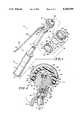
- FIG. 1is an exploded perspective view of a preferred embodiment of the present invention illustrating an acetabular cup impactor suitable for engaging and properly positioning an acetabular cup assembly;
- FIG. 2is a side, cross sectional view illustrating a split head of the acetabular cup impactor engaging a bearing component of the acetabular cup assembly.
- the split headis attached at an angle to a handle by an intervening declination adaptor;
- FIG. 3is an enlarged, side view with portions broken away illustrating removal of a declination adaptor
- FIG. 4is a side, cross sectional view of the split head directly attached to a handle without the intervening declination adaptor.
- a symmetrical acetabular cup assembly dimensioned smaller than that shown in FIGS. 1 and 2is shown held by engagement with a second gripping ridge;
- FIG. 5is a view along section 5--5 of FIG. 4, illustrating the position of a yoke of a lever arm and the split head gripping the smaller bearing component.
- FIGS. 1 and 2illustrate an acetabular cup impactor assembly 10.
- the assembly 10includes a handle 12 connected to a split head 30 by way of a declination adaptor 20.
- a movable lever arm 60is attached to the split head 30.
- the split head 30holds onto an acetabular cup assembly 110, shown disassembled.
- the longitudinally extending handle 12includes a manual grip 13, slightly contoured to increase ease of holding the assembly 10, and an extension piece 14.
- An impactor plate 15, formed from a flat steel disk,is permanently attached to one end of the manual grip 13.
- the manual grip 13is constructed of a dense polymeric material that is permanently attached to the extension piece 14.
- the extension piece 14is rigidly constructed of steel or other metal, and longitudinally extends collinear to the manual grip 13.
- the extension piece 14defines external threads 16 at its terminal end opposite the handle 12.
- the handle 12is designed to allow transfer of force applied perpendicular to the surface of the impactor plate 15 through the manual grip 13, extension piece 14, declination adaptor 20, split head 30, to the acetabular cup assembly 110.
- the declination adaptor 20is formed to define internal threads 22 extending along axis a and external threads 24 extending along axis b.
- Axis bis canted at an angle c (about 10 degrees) relative to axis a.
- the internal threads 22threadingly engage the external threads 16 of the extension piece 14, and the external threads 24 threadingly engage internal threads 34 defined in a split head support 32 of the split head 30.
- a lug 26is inserted into a notch 37 defined in the split head support32 to prevent rotation of the declination adaptor 20.
- the split head 30includes a first gripping element 36 integrally formed with and supported by the split head support 32. Positioned adjacent to the first gripping element 36 is a second gripping element 38. Taken together, the gripping elements 36 and 38 form a generally hemispherical surface that can be inserted into bearing component 114 of the acetabular cup assembly 110. To frictionally grip and hold the cup assembly 110, first and second gripping ridges 52 and 54 are defined on the split head 30. The gripping ridges 52 and 54 respectively encircle the combination ofgripping elements 36 and 38 to give annular offset contact surfaces capableof engaging differently sized acetabular cup assemblies. As shown in FIG. 2, acetabular cup assembly 110 is primarily held by action of the first gripping ridge 52. Use of the second gripping ridge 54 to hold a smaller inside diameter acetabular cup assembly is illustrated in FIGS. 4 and 5.
- the split head 30is normally biased to remain open, with the second gripping element 38 moving outward with respect to the fixed first gripping element 36 in response to the outward force of an expansion spring 46 situated in cavities 48, 50 defined in the gripping elements 36,38.
- the second gripping element 38is supported to pivot about a pivot pin 40 by a pivot arm 42.
- the pivot arm 42has defined therein a hole 44 through which the pivot pin 40 is inserted and the first gripping element 36 is attached to the pivot pin 40 via the pivot pin passing through the splint head support 32 and onto the first gripping element 36.
- the pivot pin 40may be permanently, and immovably, attached to the split head support 32. This arrangement allows a limited outward swinging movement ofthe second gripping element 38 in response to action of the spring 46. However, only a limited outward movement is permitted, because the motion of the pivot arm 42 is blocked by wall 33 of the split head support 32.
- the movable lever arm 60includes a lever armhandle 62 and a yoke 64.
- the yoke 64splits to form a first yoke arm 66 and a second yoke arm 68.
- the yoke arms 66, 68are attached to the split head 30. Movement of the lever arm handle 62 toward the handle 12 acts to move the second gripping element 38 closer to the first gripping element 36, with the pivot pin 40 acting as a fulcrum.
- the split head 30can be inserted into the acetabular cup assembly 110. Release of the lever arm 60 allows the secondgripping element 38 to move away from the first gripping element 36, in effect causing the first gripping ridge 52 of the split head 30 to engage and hold the acetabular cup assembly 110.
- FIGS. 1 and 2also illustrate the acetabular cup assembly 110 in a disassembled state (FIG. 1) and in a fully assembled configuration (FIG. 2).
- the acetabular cup assembly 110includes a shell component 112 designed to be affixed to the acetabulum of a patient to replace the natural hip socket and a bearing component 114 designed to be inserted into shell component 112.
- a lock wire 116is also provided to retain the bearing component 114 within the shell component 112.
- the shell component 112includes an outer surface 118 which can be textured to facilitate securement of the shell component 112 in place within an appropriately prepared acetabulum.
- Shell component 112is preferably made from titanium,but may be made from a cobalt chrome material.
- Shell component 112also includes a generally hemispherically shaped inner surface 120.
- Shell component 112includes a rim 124.
- the rim 124defines a plane through which bearing component 114, held by the split head 30 of the acetabular cup assembly 110, enters cavity 126 of shell component 112 formed by innersurface 120.
- Inner surface 120 of shell component 112is formed to include an arcuate groove 128 therein. The arcuate groove 128 extends around the entire periphery of cavity 126 spaced apart from rim 124 by a predetermined distance.
- Shell component 112is also formed to include anti-rotation lugs 130 on inner surface 120 of shell component 112.
- four lugsare provided.
- the lugs 130are situated below the arcuate groove 128 formed in the inner surface 120 of the shell component 112.
- the lugs 130interfere or machine into theouter surface of the bearing component as the bearing component 114 is inserted into the shell component 112 to prevent rotation of the bearing component relative to the shell component.
- Bearing component 114includes a generally hemispherically shaped outer surface 132 which is congruent or complimentary to inner surface 120 of shell component 12. Bearing component 114 also includes an inner bearing surface 134 for receiving a prosthetic femoral ball (not shown) and a radially outwardly projecting lip or flange 136 extending circumferentially around the bearing component 114.
- the bearing component 114 illustrated in the FIGS. 1-2is a nonsymmetrical bearing component. Itis understood, however, that the bearing component of the present inventionmay be a symmetrical component such as the bearing component 214 illustrated in FIGS. 4 and 5. Bearing component 114 shown in FIGS.
- bearing component 114is also formed to include radially outwardly opening arcuate groove 140 spaced apart from flange 136 by the same predetermined distancethat arcuate groove 128 is spaced apart from rim 124 of shell component 112.
- Bearing component 114is preferably made from a polymeric material such as ultra-high molecular weight polyethylene (UHMWPE).
- UHMWPEultra-high molecular weight polyethylene
- the bearing component 114could be made of other types of implantable bearing material.
- Lock wire 116is a serpentine shaped wire which is preferably made from cobalt chrome material and shaped by conventional wire forming techniques.Titanium may also be used to make wire 116.
- the lock wire 116 shown in FIGS. 1 and 2has a somewhat hexagonal shape and includes six engaging sections 142.
- the wire 116can be either serpentine shaped as shown in FIGS. 1 and 2 or polygon shaped having any number of sides.
- a gap 144is provided between two adjacent sections 142 of lock wire 116 to permit lockwire 116 to expand radially outwardly. Corner portions 146 are situated between the side sections 142.
- the wire 116may be conventionally heat treated to increase its strength. When assembled, lock wire 116 is inserted into the arcuate groove 128 of shell component 112. Corner portions 146 of the lock wire 116 remain inside arcuate groove 128 formed in shell component 112 to retain lock wire 16 inside the arcuate groove 128.
- outer surface 132 of bearing component 114is inserted into cavity 126 of shell component 112.
- the corner portions 146snap into place within arcuate groove 128, locking thebearing component 114 to the shell component 112. Since there are no preformed notches in outer surface 132 of bearing component 114 to receivelugs 130, the bearing component 114 can be inserted into shell component 112 at any desired orientation not limited by such preformed notches. Lockwire 116 therefore retains bearing component 114 inside shell component 112regardless of the position of bearing component 114 relative to shell component 112. The surgeon positions the bearing component 114 in the mostadvantageous position 112 to reduce the likelihood that a femur ball (not shown) will become dislodged from the cavity 135 defined by inner surface 134.
- the surgeonholds and positions the assembled acetabular cup assembly 110 (or the bearing component 114 when the shell component 112 is already installed in a patients's acetabulum) with the aid of the acetabular cup impactor assembly 10.
- a surgeoninserts the split head 30 into the cavity 135 defined by the bearing component 114 while the movable lever arm 60 is depressed toward the handle 12.
- the movable lever arm 60is released, causing the first and second gripping elements 36 and 38 of the split head 30 to move apart.
- the first gripping ridge 52frictionally engages inner surface 134 of the bearing component 114.
- a surgeonpositions the coupled impactor assembly 10 and cup assembly 110 at a desired position relative to a patient's acetabulum.
- a mallet(not shown) or other hammering means is used to strike the impactor plate 15, driving the acetabular cup impactor toward the acetabulum. Since it is critical that cup assembly 110 retain its initial, undistorted configuration, this driving force is smoothly and evenly transmitted to the cup assembly 110 by contact with a first annular impact surface 53 and a second impact surface 55.
- the impact surfaces 53, 55are positioned to extend substantially perpendicular to the first gripping 52, and lies in contact with the bearing component 114.
- the driving forceis transferred from surface 53 to the bearing component 114, providing a substantially stress-free driving force that secures the cup assembly 110 in its proper position in the acetabulum of a patients hip.
- the declination adaptor 20can beremoved and split head 30 directly attached to the extension piece 14. As shown in FIG. 3, removal of the declination adaptor 20 from its threaded attachment between the split head 30 and extension piece 14 first requiresunscrewing the combination of the split head 30 and declination adaptor 20 from the extension piece 14.
- a tool 70 having a hex head 72is inserted and rotated (direction of rotation indicated by arrow) to unscrew the external threads 24 of the declination adaptor 20 from engagement with internal threads 34 of the split head 30.
- the split head 30is then directly attached to the extension piece 14 by screwingly engaging the external threads 16 of the extension piece 14 withthe internal threads 34 of the split head 30.
- FIGS. 4 and 5illustrate holding engagement of the acetabular cup impactor assembly 10 (without declination adaptor 20) with an acetabular cup assembly 210.
- the acetabular cup assembly 210has a shell component 212 comparable to that of previously described shell component 112, but havingslightly smaller overall dimensions. Fitting into the shell component 212 is a symmetrically configured bearing component 214.
- the bearing component214is slightly smaller than bearing component 114, so that the smaller diameter second gripping ridge 54 (as compared to first gripping ridge 52)frictionally engages the bearing component 214.
- placement ofthe acetabular cup assembly 210follows the procedure previously noted for placement of acetabular cup assembly 110, with the exception that the substantially stress free driving force is transmitted through a second annular impact surface 55 to the cup assembly 210.
Landscapes
- Health & Medical Sciences (AREA)
- Transplantation (AREA)
- Orthopedic Medicine & Surgery (AREA)
- Heart & Thoracic Surgery (AREA)
- Cardiology (AREA)
- Oral & Maxillofacial Surgery (AREA)
- Engineering & Computer Science (AREA)
- Biomedical Technology (AREA)
- Physical Education & Sports Medicine (AREA)
- Vascular Medicine (AREA)
- Life Sciences & Earth Sciences (AREA)
- Animal Behavior & Ethology (AREA)
- General Health & Medical Sciences (AREA)
- Public Health (AREA)
- Veterinary Medicine (AREA)
- Prostheses (AREA)
Abstract
Description
Claims (26)
Priority Applications (1)
| Application Number | Priority Date | Filing Date | Title |
|---|---|---|---|
| US07/778,509US5169399A (en) | 1991-10-17 | 1991-10-17 | Acetabular cup impactor |
Applications Claiming Priority (1)
| Application Number | Priority Date | Filing Date | Title |
|---|---|---|---|
| US07/778,509US5169399A (en) | 1991-10-17 | 1991-10-17 | Acetabular cup impactor |
Publications (1)
| Publication Number | Publication Date |
|---|---|
| US5169399Atrue US5169399A (en) | 1992-12-08 |
Family
ID=25113587
Family Applications (1)
| Application Number | Title | Priority Date | Filing Date |
|---|---|---|---|
| US07/778,509Expired - LifetimeUS5169399A (en) | 1991-10-17 | 1991-10-17 | Acetabular cup impactor |
Country Status (1)
| Country | Link |
|---|---|
| US (1) | US5169399A (en) |
Cited By (98)
| Publication number | Priority date | Publication date | Assignee | Title |
|---|---|---|---|---|
| DE9402847U1 (en)* | 1994-02-16 | 1994-07-28 | Artos Medizinische Produkte Gmbh, 12277 Berlin | Acetabular cup |
| FR2701206A1 (en)* | 1993-02-09 | 1994-08-12 | Medinov Sa | Impacter equipment for a polyethylene core or cup for acetabular implant |
| US5364403A (en)* | 1993-09-20 | 1994-11-15 | Zimmer, Inc. | Acetabular cup positioner |
| EP0612509A3 (en)* | 1993-02-23 | 1995-02-22 | W Lennox D | Adjustable prosthetic socket component for articulating anatomical joints. |
| US5405404A (en)* | 1993-10-07 | 1995-04-11 | Intermedics Orthopedics, Inc. | Instrument for disassembling a bipolar hip prosthesis |
| WO1995016413A1 (en)* | 1993-12-16 | 1995-06-22 | Endocare Ag | Elliptic acetabular component for a hip prosthesis |
| US5431657A (en)* | 1994-05-23 | 1995-07-11 | Zimmer, Inc. | Instrument for installing an acetabular cup assembly |
| US5486181A (en)* | 1994-08-04 | 1996-01-23 | Implex Corporation | Acetabular cup, method and tool and installing the same |
| US5527317A (en)* | 1993-10-29 | 1996-06-18 | Howniedica International | Method and apparatus for implanting an acetabular cup |
| US5540697A (en)* | 1993-02-12 | 1996-07-30 | U.S. Medical Products, Inc. | Prosthetic socket installation apparatus and method |
| GB2299758A (en)* | 1995-04-10 | 1996-10-16 | Finsbury | Surgical tool for use in joint replacement |
| US5571111A (en)* | 1995-05-01 | 1996-11-05 | Aboczky; Robert I. | Instrument for orienting, inserting and impacting an acetabular cup prosthesis including prosthesis retaining head arrangement |
| US5683399A (en)* | 1995-12-01 | 1997-11-04 | Stelkast Incorporated | Acetabular cup insertion tool |
| WO1997042915A1 (en)* | 1996-05-09 | 1997-11-20 | Waldemar Link (Gmbh & Co.) | Acetabular prosthesis and surgical instrument for insertion thereof |
| US5817096A (en)* | 1996-11-25 | 1998-10-06 | Othy, Inc. | Tool driver |
| US5904688A (en)* | 1997-12-30 | 1999-05-18 | Bristol-Myers Squibb Co. | Orthopaedic assembly including an acetabular cup and cup inserter |
| US5954727A (en)* | 1993-10-29 | 1999-09-21 | Howmedica Inc. | Acetabular cup positioning tool and method of positioning an acetabular cup |
| DE19820721A1 (en)* | 1998-04-30 | 1999-11-04 | Ceramtec Ag | Instrument for handling components of joint prostheses |
| WO1999056677A1 (en)* | 1998-04-30 | 1999-11-11 | Ceramtec Ag | Instrument for manipulating components of joint prostheses |
| US6063124A (en)* | 1999-03-01 | 2000-05-16 | Amstutz; Harlan C. | Acetabular cup prosthesis insertion and removal assembly and technique |
| DE10031271A1 (en)* | 2000-06-27 | 2002-01-10 | Paul Schwabe | Implantation instrument for hip socket has implant and operating ends, clamping jaws with in-between tension springs, and guide. |
| US20040010262A1 (en)* | 2002-07-12 | 2004-01-15 | Parkinson Fred W. | Tool for gripping and orthopedic implant |
| DE19644559A1 (en)* | 1996-06-25 | 2004-02-19 | Cerasiv Gmbh Innovatives Keramik-Engineering | Implement and method for removing ceramic ball-socket inserts from metal dish of hip-joint endoprosthesis involve positioning plate, threaded central hole, for threaded bar and plate springs |
| EP1438936A1 (en) | 2003-01-17 | 2004-07-21 | Tornier | Ancillary for implanting a prosthetic acetabular cup for a hip prosthesis |
| US20040153063A1 (en)* | 2003-02-04 | 2004-08-05 | Harris Brian R. | Acetabular impactor |
| WO2004069107A1 (en)* | 2003-02-03 | 2004-08-19 | Depuy International Limited | An instrument for positioning a cup component of an orthopaedic joint prosthesis |
| US20050038443A1 (en)* | 2002-12-12 | 2005-02-17 | Hedley Anthony K. | Surgical tools for joint replacement |
| US20050085823A1 (en)* | 2003-10-21 | 2005-04-21 | Murphy Stephen B. | Acetabular impactor |
| US20050119666A1 (en)* | 2003-11-28 | 2005-06-02 | Bubb Stephen K. | Orthopedic and dental implant system and method |
| US6936037B2 (en) | 2002-12-31 | 2005-08-30 | Kci Licensing, Inc. | Tissue closure treatment system, patient interface and method |
| US20050228395A1 (en)* | 2004-03-05 | 2005-10-13 | Benoist Girard Sas | Prosthetic acetabular cup inserter |
| US20050268425A1 (en)* | 2004-04-20 | 2005-12-08 | Clemons William E Sr | Surface cleaner |
| AT413259B (en)* | 2002-11-08 | 2006-01-15 | Falcon Medical Medizinische Sp | ZWISCHENSTÜCK |
| US6997928B1 (en) | 2002-06-10 | 2006-02-14 | Wright Medical Technology, Inc. | Apparatus for and method of providing a hip replacement |
| US7004946B2 (en) | 2002-10-30 | 2006-02-28 | Symmetry Medical, Inc. | Acetabular cup impactor |
| WO2007042227A1 (en)* | 2005-10-07 | 2007-04-19 | Trokamed Gmbh | Device for handling an artificial acetabular fossa |
| US20070156155A1 (en)* | 2006-01-03 | 2007-07-05 | Parker Brad A | Surgical cup impactor |
| US20070173856A1 (en)* | 2006-01-25 | 2007-07-26 | Parker Brad A | Split thread orthopaedic implant impactor |
| US20070270783A1 (en)* | 2004-06-22 | 2007-11-22 | Lukas Zumsteg | Device for Placing or Removing Joints or Joints Sockets |
| US20080009953A1 (en)* | 2006-05-03 | 2008-01-10 | Benoist Girard Sas | Flanged prosthetic acetabular cup |
| US20080077249A1 (en)* | 2004-10-13 | 2008-03-27 | Thomas Gradel | Instruments for Setting Acetabular Cup |
| US7351250B2 (en) | 2002-08-21 | 2008-04-01 | Kci Licensing, Inc. | Circumferential medical closure device and method |
| US7381211B2 (en) | 2002-08-21 | 2008-06-03 | Kci Licensing, Inc. | Medical closure screen device and method |
| US20080133023A1 (en)* | 2006-10-05 | 2008-06-05 | Zimmer Technology, Inc. | Provisional prosthetic component formed of multiple materials |
| GB2445087A (en)* | 2006-12-21 | 2008-06-25 | Precimed Sa | Prosthesis component holder attachable to an inserter handle |
| US7410495B2 (en) | 2002-08-21 | 2008-08-12 | Kci Licensing, Inc. | Medical closure clip system and method |
| US7413570B2 (en) | 2002-08-21 | 2008-08-19 | Kci Licensing, Inc. | Medical closure screen installation systems and methods |
| US7413571B2 (en) | 2002-08-21 | 2008-08-19 | Kci Licensing, Inc. | Flexible medical closure screen and method |
| US20080269765A1 (en)* | 2007-04-27 | 2008-10-30 | Zimmer, Inc. | Instrument and method for implanting a prosthetic component |
| US7445639B2 (en) | 2001-02-23 | 2008-11-04 | Biomet Manufacturing Corp. | Knee joint prosthesis |
| US7497874B1 (en) | 2001-02-23 | 2009-03-03 | Biomet Manufacturing Corp. | Knee joint prosthesis |
| US20090192626A1 (en)* | 2008-01-25 | 2009-07-30 | Depuy Products, Inc. | Constraining ring inserter |
| US7708739B2 (en) | 2005-03-31 | 2010-05-04 | Depuy Products, Inc. | Controlled force impacting device |
| US7727282B2 (en) | 2006-03-17 | 2010-06-01 | Biomet Manufacturing Corp. | Method and apparatus for implanting a prosthesis |
| JP2010220921A (en)* | 2009-03-25 | 2010-10-07 | Japan Medical Materials Corp | Operating instrument for artificial joint replacement |
| US7976519B2 (en) | 2002-12-31 | 2011-07-12 | Kci Licensing, Inc. | Externally-applied patient interface system and method |
| US8062331B2 (en) | 2002-08-21 | 2011-11-22 | Kci Licensing, Inc. | Internal and external medical closure screen systems and methods |
| US8123815B2 (en) | 2008-11-24 | 2012-02-28 | Biomet Manufacturing Corp. | Multiple bearing acetabular prosthesis |
| US8157869B2 (en) | 2007-01-10 | 2012-04-17 | Biomet Manufacturing Corp. | Knee joint prosthesis system and method for implantation |
| US8163028B2 (en) | 2007-01-10 | 2012-04-24 | Biomet Manufacturing Corp. | Knee joint prosthesis system and method for implantation |
| US8187280B2 (en) | 2007-10-10 | 2012-05-29 | Biomet Manufacturing Corp. | Knee joint prosthesis system and method for implantation |
| US20120136360A1 (en)* | 2010-11-25 | 2012-05-31 | Benoist Girard Sas | Prosthetic acetabular cup inserter and impactor |
| US8236004B2 (en) | 2006-05-01 | 2012-08-07 | Greatbatch Medical S.A. | Inserter for minimally invasive joint surgery having an interchangeable prosthesis engaging piston |
| US20120232562A1 (en)* | 2011-03-07 | 2012-09-13 | OrthoWin S.A. | Pneumatic Surgical Instrument and Corresponding Methods for Implanting, Extracting and Reorienting Orthopedic Implants |
| US8277457B1 (en) | 2004-12-09 | 2012-10-02 | Greatbatch Medical S.A. | Orthopaedic inserter using a collet mechanism |
| US8308810B2 (en) | 2009-07-14 | 2012-11-13 | Biomet Manufacturing Corp. | Multiple bearing acetabular prosthesis |
| US8328873B2 (en) | 2007-01-10 | 2012-12-11 | Biomet Manufacturing Corp. | Knee joint prosthesis system and method for implantation |
| US8398650B1 (en) | 2009-01-27 | 2013-03-19 | Greatbatch Medical S.A. | Offset cup impactor with an expandable dome for double mobility implants |
| US20130226186A1 (en)* | 2011-08-26 | 2013-08-29 | Greatbatch Medical S.A. | Straight Cup Impactor |
| US8562616B2 (en) | 2007-10-10 | 2013-10-22 | Biomet Manufacturing, Llc | Knee joint prosthesis system and method for implantation |
| US8585709B2 (en) | 2011-01-17 | 2013-11-19 | Greatbatch Medical S.A. | Straight cup impactor with lever arm |
| US20130331849A1 (en)* | 2012-06-07 | 2013-12-12 | Howmedica Osteonics Corp. | Glenosphere inserter and impactor |
| DE102013200924A1 (en)* | 2013-01-22 | 2014-07-24 | Erich Johann Müller | Razor tool for minimally invasive prosthesis revision |
| US20140276842A1 (en)* | 2013-03-14 | 2014-09-18 | Zimmer, Inc. | Orthopedic device holder and related system and method |
| US8961528B2 (en) | 2010-08-27 | 2015-02-24 | Greatbatch Medical S.A. | Offset cup impactor with a grasping plate for double mobility implants |
| US9028502B2 (en) | 2011-09-23 | 2015-05-12 | Greatbatch Medical S.A. | Ceramic implant holder |
| US9039710B2 (en) | 2010-12-07 | 2015-05-26 | Zimmer, Inc. | Prosthetic inserter |
| US9119731B2 (en) | 2011-01-17 | 2015-09-01 | Greatbach Medical S.A. | Straight cup impactor |
| US9168154B2 (en) | 2013-12-29 | 2015-10-27 | Kambiz Behzadi | Prosthesis installation systems and methods |
| US9220612B2 (en) | 2013-12-29 | 2015-12-29 | Kambiz Behzadi | Prosthesis positioning systems and methods |
| US20160213492A1 (en)* | 2015-01-27 | 2016-07-28 | Trigon International Corporation | Impactor adaptor and screw assembly |
| US9408956B2 (en) | 2010-09-24 | 2016-08-09 | Kci Licensing, Inc. | Cellular control and tissue regeneration systems and methods |
| US9456930B2 (en) | 2011-07-12 | 2016-10-04 | Kci Licensing, Inc. | Topical vacuum-press surgical incisional dressings, surgical adjuncts, hybrids and composites |
| US9569566B2 (en) | 2011-12-12 | 2017-02-14 | Zam Research Llc | Simulation and control system and method using contact, pressure waves and factor controls for cell regeneration, tissue closure and related applications |
| US9968488B2 (en) | 2012-11-12 | 2018-05-15 | Kci Usa, Inc. | Externally-applied patient interface system and method |
| US10172722B2 (en) | 2013-12-29 | 2019-01-08 | Kambiz Behzadi | Prosthesis installation systems and methods |
| US10245162B2 (en) | 2013-12-29 | 2019-04-02 | Kambiz Behzadi | Prosthesis installation systems and methods |
| US10245160B2 (en) | 2013-12-29 | 2019-04-02 | Kambiz Behzadi | Prosthesis installation systems and methods |
| US10363344B2 (en) | 2002-12-31 | 2019-07-30 | Kci Licensing, Inc. | Externally-applied patient interface system and method with a controlled region for implanted or buried bio-reactor |
| US10390846B2 (en) | 2002-06-10 | 2019-08-27 | Microport Orthopedics Holdings Inc. | Apparatus for and method of providing a hip replacement |
| US10456271B2 (en) | 2013-12-29 | 2019-10-29 | Kambiz Behzadi | Prosthesis revision systems and methods |
| US10478318B2 (en) | 2013-12-29 | 2019-11-19 | Kambiz Behzadi | Prosthesis installation systems and methods |
| US10492956B2 (en) | 2013-03-15 | 2019-12-03 | Kci Licensing, Inc. | Topical vacuum-press surgical incisional dressings, surgical adjuncts, hybrids and composites |
| US20190389043A1 (en)* | 2018-06-22 | 2019-12-26 | United Technologies Corporation | Immobilizer tool set for bolt installation and method |
| WO2020012173A1 (en) | 2018-07-12 | 2020-01-16 | Matortho Limited | Prosthesis impactor assembly |
| US10610379B2 (en) | 2013-12-29 | 2020-04-07 | Kambiz Behzadi | Prosthesis installation systems and methods |
| US11090163B1 (en)* | 2021-01-09 | 2021-08-17 | Zafer Termanini | Interlocking reverse hip prosthesis with removable tapered central post |
| US20230172730A1 (en)* | 2020-04-20 | 2023-06-08 | Howmedica Osteonics Corp. | Inserter for glenosphere |
Citations (9)
| Publication number | Priority date | Publication date | Assignee | Title |
|---|---|---|---|---|
| US472311A (en)* | 1892-04-05 | John w | ||
| US614724A (en)* | 1898-11-22 | William jennings | ||
| US627669A (en)* | 1898-12-02 | 1899-06-27 | Frank B Kendrick | Watchmaker's tool. |
| US1152239A (en)* | 1915-06-18 | 1915-08-31 | Charles Thom | Tool. |
| US2271012A (en)* | 1939-08-07 | 1942-01-27 | Cleveland Pneumatic Tool Co | Riveting clamp |
| US2420020A (en)* | 1944-12-09 | 1947-05-06 | Bmc Mfg Corp | Lever-actuated pivoted-jaw wrench |
| US4870747A (en)* | 1987-09-25 | 1989-10-03 | Amp Incorporated | Wire insertion tooling assembly |
| US5048805A (en)* | 1990-07-27 | 1991-09-17 | Avtool, Inc. | Clamp |
| US5059196A (en)* | 1991-03-07 | 1991-10-22 | Dow Corning Wright Corporation | Femoral prosthesis holder/driver tool and method of implantation using same |
- 1991
- 1991-10-17USUS07/778,509patent/US5169399A/ennot_activeExpired - Lifetime
Patent Citations (9)
| Publication number | Priority date | Publication date | Assignee | Title |
|---|---|---|---|---|
| US472311A (en)* | 1892-04-05 | John w | ||
| US614724A (en)* | 1898-11-22 | William jennings | ||
| US627669A (en)* | 1898-12-02 | 1899-06-27 | Frank B Kendrick | Watchmaker's tool. |
| US1152239A (en)* | 1915-06-18 | 1915-08-31 | Charles Thom | Tool. |
| US2271012A (en)* | 1939-08-07 | 1942-01-27 | Cleveland Pneumatic Tool Co | Riveting clamp |
| US2420020A (en)* | 1944-12-09 | 1947-05-06 | Bmc Mfg Corp | Lever-actuated pivoted-jaw wrench |
| US4870747A (en)* | 1987-09-25 | 1989-10-03 | Amp Incorporated | Wire insertion tooling assembly |
| US5048805A (en)* | 1990-07-27 | 1991-09-17 | Avtool, Inc. | Clamp |
| US5059196A (en)* | 1991-03-07 | 1991-10-22 | Dow Corning Wright Corporation | Femoral prosthesis holder/driver tool and method of implantation using same |
Non-Patent Citations (10)
| Title |
|---|
| "Discover":Discover the Next Generation in Acetabular Technology, Surgical Technique, pp. 1-14, date unknown. |
| "McCutchen Hip Surgical Technique", Dow Corning Wright, pp. 1-10, date unknown. |
| D. Hungerford, M.D. et al., "The P.C.A. Primary Hip System Surgical Technique", Howmedica Surgical Techniques, pp. 1-6, date unknown. |
| D. Hungerford, M.D. et al., The P.C.A. Primary Hip System Surgical Technique , Howmedica Surgical Techniques, pp. 1 6, date unknown.* |
| Discover : Discover the Next Generation in Acetabular Technology, Surgical Technique, pp. 1 14, date unknown.* |
| H Dunn, M.D., "Surgical Technique for Primary Hip Arthroplasty", Univ. of Utah College of Medicine, Salt Lake City, Utah, pp. 1-19, date unknown. |
| H Dunn, M.D., Surgical Technique for Primary Hip Arthroplasty , Univ. of Utah College of Medicine, Salt Lake City, Utah, pp. 1 19, date unknown.* |
| McCutchen Hip Surgical Technique , Dow Corning Wright, pp. 1 10, date unknown.* |
| R. Turner, M.D. et al., "The Howmedica Precision Hip System", pp. 1-6, date unknown. |
| R. Turner, M.D. et al., The Howmedica Precision Hip System , pp. 1 6, date unknown.* |
Cited By (165)
| Publication number | Priority date | Publication date | Assignee | Title |
|---|---|---|---|---|
| FR2701206A1 (en)* | 1993-02-09 | 1994-08-12 | Medinov Sa | Impacter equipment for a polyethylene core or cup for acetabular implant |
| US5540697A (en)* | 1993-02-12 | 1996-07-30 | U.S. Medical Products, Inc. | Prosthetic socket installation apparatus and method |
| US5507824A (en)* | 1993-02-23 | 1996-04-16 | Lennox; Dennis W. | Adjustable prosthetic socket component, for articulating anatomical joints |
| EP0612509A3 (en)* | 1993-02-23 | 1995-02-22 | W Lennox D | Adjustable prosthetic socket component for articulating anatomical joints. |
| US5364403A (en)* | 1993-09-20 | 1994-11-15 | Zimmer, Inc. | Acetabular cup positioner |
| US5405404A (en)* | 1993-10-07 | 1995-04-11 | Intermedics Orthopedics, Inc. | Instrument for disassembling a bipolar hip prosthesis |
| US5954727A (en)* | 1993-10-29 | 1999-09-21 | Howmedica Inc. | Acetabular cup positioning tool and method of positioning an acetabular cup |
| US5527317A (en)* | 1993-10-29 | 1996-06-18 | Howniedica International | Method and apparatus for implanting an acetabular cup |
| NL9302200A (en)* | 1993-12-16 | 1995-07-17 | Endocare Ag | Elliptical acetabulum component for a hip prosthesis. |
| WO1995016413A1 (en)* | 1993-12-16 | 1995-06-22 | Endocare Ag | Elliptic acetabular component for a hip prosthesis |
| DE9402847U1 (en)* | 1994-02-16 | 1994-07-28 | Artos Medizinische Produkte Gmbh, 12277 Berlin | Acetabular cup |
| US5431657A (en)* | 1994-05-23 | 1995-07-11 | Zimmer, Inc. | Instrument for installing an acetabular cup assembly |
| US5486181A (en)* | 1994-08-04 | 1996-01-23 | Implex Corporation | Acetabular cup, method and tool and installing the same |
| WO1996003931A1 (en)* | 1994-08-04 | 1996-02-15 | Implex Corporation | Acetabular cup, method and tool for installing the same |
| US5571200A (en)* | 1994-08-04 | 1996-11-05 | Implex Corporation | Acetabular cup, method and tool for installing the same |
| GB2299758A (en)* | 1995-04-10 | 1996-10-16 | Finsbury | Surgical tool for use in joint replacement |
| GB2299758B (en)* | 1995-04-10 | 1998-07-22 | Finsbury | Surgical tool |
| US5571111A (en)* | 1995-05-01 | 1996-11-05 | Aboczky; Robert I. | Instrument for orienting, inserting and impacting an acetabular cup prosthesis including prosthesis retaining head arrangement |
| US5683399A (en)* | 1995-12-01 | 1997-11-04 | Stelkast Incorporated | Acetabular cup insertion tool |
| WO1997042915A1 (en)* | 1996-05-09 | 1997-11-20 | Waldemar Link (Gmbh & Co.) | Acetabular prosthesis and surgical instrument for insertion thereof |
| DE19644559A1 (en)* | 1996-06-25 | 2004-02-19 | Cerasiv Gmbh Innovatives Keramik-Engineering | Implement and method for removing ceramic ball-socket inserts from metal dish of hip-joint endoprosthesis involve positioning plate, threaded central hole, for threaded bar and plate springs |
| DE19644559B4 (en)* | 1996-06-25 | 2005-07-28 | Cerasiv Gmbh Innovatives Keramik-Engineering | Tool for removing conically clamped ceramic cup inserts from the metal cup of a hip joint endoprosthesis |
| US5817096A (en)* | 1996-11-25 | 1998-10-06 | Othy, Inc. | Tool driver |
| US5904688A (en)* | 1997-12-30 | 1999-05-18 | Bristol-Myers Squibb Co. | Orthopaedic assembly including an acetabular cup and cup inserter |
| DE19820721A1 (en)* | 1998-04-30 | 1999-11-04 | Ceramtec Ag | Instrument for handling components of joint prostheses |
| WO1999056677A1 (en)* | 1998-04-30 | 1999-11-11 | Ceramtec Ag | Instrument for manipulating components of joint prostheses |
| US6468281B1 (en) | 1998-04-30 | 2002-10-22 | Ceramtec Ag | Instrument for manipulating components of joint prostheses |
| US6063124A (en)* | 1999-03-01 | 2000-05-16 | Amstutz; Harlan C. | Acetabular cup prosthesis insertion and removal assembly and technique |
| DE10031271A1 (en)* | 2000-06-27 | 2002-01-10 | Paul Schwabe | Implantation instrument for hip socket has implant and operating ends, clamping jaws with in-between tension springs, and guide. |
| DE10031271B4 (en)* | 2000-06-27 | 2007-04-12 | Paul Schwabe | Hüftpfannenimplantationsgerät |
| US7497874B1 (en) | 2001-02-23 | 2009-03-03 | Biomet Manufacturing Corp. | Knee joint prosthesis |
| US7445639B2 (en) | 2001-02-23 | 2008-11-04 | Biomet Manufacturing Corp. | Knee joint prosthesis |
| US10390846B2 (en) | 2002-06-10 | 2019-08-27 | Microport Orthopedics Holdings Inc. | Apparatus for and method of providing a hip replacement |
| US7833229B2 (en) | 2002-06-10 | 2010-11-16 | Wright Medical Technology Inc. | Apparatus for and method of providing a hip replacement |
| US8740907B2 (en) | 2002-06-10 | 2014-06-03 | Microport Orthopedics Holdings Inc. | Apparatus for and method of providing a hip replacement |
| US6997928B1 (en) | 2002-06-10 | 2006-02-14 | Wright Medical Technology, Inc. | Apparatus for and method of providing a hip replacement |
| US7037311B2 (en)* | 2002-07-12 | 2006-05-02 | Zimmer Technology, Inc. | Tool for gripping an orthopedic implant |
| US20040010262A1 (en)* | 2002-07-12 | 2004-01-15 | Parkinson Fred W. | Tool for gripping and orthopedic implant |
| US7410495B2 (en) | 2002-08-21 | 2008-08-12 | Kci Licensing, Inc. | Medical closure clip system and method |
| US7413570B2 (en) | 2002-08-21 | 2008-08-19 | Kci Licensing, Inc. | Medical closure screen installation systems and methods |
| US8123781B2 (en) | 2002-08-21 | 2012-02-28 | Kci Licensing, Inc. | Screen devices and methods for closing tissue separations |
| US7413571B2 (en) | 2002-08-21 | 2008-08-19 | Kci Licensing, Inc. | Flexible medical closure screen and method |
| US8070773B2 (en) | 2002-08-21 | 2011-12-06 | Kci Licensing, Inc. | Medical closure methods and screen devices |
| US8062331B2 (en) | 2002-08-21 | 2011-11-22 | Kci Licensing, Inc. | Internal and external medical closure screen systems and methods |
| US7351250B2 (en) | 2002-08-21 | 2008-04-01 | Kci Licensing, Inc. | Circumferential medical closure device and method |
| US7381211B2 (en) | 2002-08-21 | 2008-06-03 | Kci Licensing, Inc. | Medical closure screen device and method |
| US7004946B2 (en) | 2002-10-30 | 2006-02-28 | Symmetry Medical, Inc. | Acetabular cup impactor |
| AT413259B (en)* | 2002-11-08 | 2006-01-15 | Falcon Medical Medizinische Sp | ZWISCHENSTÜCK |
| US20050038443A1 (en)* | 2002-12-12 | 2005-02-17 | Hedley Anthony K. | Surgical tools for joint replacement |
| US6951553B2 (en) | 2002-12-31 | 2005-10-04 | Kci Licensing, Inc | Tissue closure treatment system and method with externally-applied patient interface |
| US10363344B2 (en) | 2002-12-31 | 2019-07-30 | Kci Licensing, Inc. | Externally-applied patient interface system and method with a controlled region for implanted or buried bio-reactor |
| US8956335B2 (en) | 2002-12-31 | 2015-02-17 | Kci Licensing, Inc. | Externaly-applied patient interface system and method |
| US7976519B2 (en) | 2002-12-31 | 2011-07-12 | Kci Licensing, Inc. | Externally-applied patient interface system and method |
| US6936037B2 (en) | 2002-12-31 | 2005-08-30 | Kci Licensing, Inc. | Tissue closure treatment system, patient interface and method |
| US20040215200A1 (en)* | 2003-01-17 | 2004-10-28 | Alain Tornier | Ancillary tool and method for positioning a prosthetic acetabulum of a hip prosthesis |
| EP1438936A1 (en) | 2003-01-17 | 2004-07-21 | Tornier | Ancillary for implanting a prosthetic acetabular cup for a hip prosthesis |
| FR2850010A1 (en) | 2003-01-17 | 2004-07-23 | Tornier Sa | PROSTHETIC COTYL POSITION ANCILLARY FOR A HIP PROSTHESIS |
| US8821503B2 (en) | 2003-01-17 | 2014-09-02 | Tornier Sas | Ancillary tool and method for positioning a prosthetic acetabulum of a hip prosthesis |
| US20080255568A1 (en)* | 2003-01-17 | 2008-10-16 | Tornier | Ancillary tool and method for positioning a prosthetic acetabulum of a hip prosthesis |
| US7396357B2 (en) | 2003-01-17 | 2008-07-08 | Tornier Sas | Ancillary tool and method for positioning a prosthetic acetabulum of a hip prosthesis |
| WO2004069107A1 (en)* | 2003-02-03 | 2004-08-19 | Depuy International Limited | An instrument for positioning a cup component of an orthopaedic joint prosthesis |
| JP4833055B2 (en)* | 2003-02-03 | 2011-12-07 | デピュー インターナショナル リミテッド | Instrument for positioning cup components of orthopedic joints |
| JP2006517817A (en)* | 2003-02-03 | 2006-08-03 | デピュイ インターナショナル リミテッド | Instrument for positioning cup components of orthopedic joints |
| US8021370B2 (en)* | 2003-02-03 | 2011-09-20 | Depuy International Ltd. | Instrument for positioning a cup component of an orthopaedic joint prosthesis |
| US20070250066A1 (en)* | 2003-02-03 | 2007-10-25 | Gary Fenton | Instrument for Positioning a Cup Component of an Orthopaedic Joint Prosthesis |
| US20040153063A1 (en)* | 2003-02-04 | 2004-08-05 | Harris Brian R. | Acetabular impactor |
| US7247158B2 (en) | 2003-02-04 | 2007-07-24 | Wright Medical Technology, Inc. | Acetabular impactor |
| US20050085823A1 (en)* | 2003-10-21 | 2005-04-21 | Murphy Stephen B. | Acetabular impactor |
| US7037310B2 (en)* | 2003-10-21 | 2006-05-02 | Wright Medical Technology Inc | Acetabular impactor |
| US20050119666A1 (en)* | 2003-11-28 | 2005-06-02 | Bubb Stephen K. | Orthopedic and dental implant system and method |
| US7326217B2 (en) | 2003-11-28 | 2008-02-05 | Bubb Stephen K | Orthopedic and dental implant system and method |
| US20050228395A1 (en)* | 2004-03-05 | 2005-10-13 | Benoist Girard Sas | Prosthetic acetabular cup inserter |
| US7341593B2 (en) | 2004-03-05 | 2008-03-11 | Benoist Girard Sas | Prosthetic acetabular cup inserter |
| US20050268425A1 (en)* | 2004-04-20 | 2005-12-08 | Clemons William E Sr | Surface cleaner |
| US8801724B2 (en)* | 2004-06-22 | 2014-08-12 | Smith And Nephew Orthopaedics Ag | Device for placing or removing joints or joint sockets |
| US20070270783A1 (en)* | 2004-06-22 | 2007-11-22 | Lukas Zumsteg | Device for Placing or Removing Joints or Joints Sockets |
| US10398570B2 (en) | 2004-10-13 | 2019-09-03 | Thomas Gradel | Instruments for setting acetabular cup |
| US9814603B2 (en)* | 2004-10-13 | 2017-11-14 | Thomas Gradel | Instruments for setting acetabular cup |
| JP2012120870A (en)* | 2004-10-13 | 2012-06-28 | Thomas Gradel | Instrument for setting acetabular cup |
| US20080077249A1 (en)* | 2004-10-13 | 2008-03-27 | Thomas Gradel | Instruments for Setting Acetabular Cup |
| US9474628B2 (en) | 2004-10-13 | 2016-10-25 | Thomas Gradel | Instruments for setting acetabular cup |
| US8277457B1 (en) | 2004-12-09 | 2012-10-02 | Greatbatch Medical S.A. | Orthopaedic inserter using a collet mechanism |
| US7708739B2 (en) | 2005-03-31 | 2010-05-04 | Depuy Products, Inc. | Controlled force impacting device |
| WO2007042227A1 (en)* | 2005-10-07 | 2007-04-19 | Trokamed Gmbh | Device for handling an artificial acetabular fossa |
| DE102005048484A1 (en)* | 2005-10-07 | 2007-04-19 | Trokamed Gmbh | Device for handling an artificial hip socket |
| US20070156155A1 (en)* | 2006-01-03 | 2007-07-05 | Parker Brad A | Surgical cup impactor |
| US20070173856A1 (en)* | 2006-01-25 | 2007-07-26 | Parker Brad A | Split thread orthopaedic implant impactor |
| US7621921B2 (en) | 2006-01-25 | 2009-11-24 | Symmetry Medical, Inc | Split thread orthopaedic implant impactor |
| US20100049257A1 (en)* | 2006-01-25 | 2010-02-25 | Symmetry Medical, Inc. | Split thread orthopaedic implant impactor |
| US8142439B2 (en) | 2006-01-25 | 2012-03-27 | Symmetry Medical Manufacturing, Inc. | Method of connecting an impactor to an orthopaedic implant |
| US7727282B2 (en) | 2006-03-17 | 2010-06-01 | Biomet Manufacturing Corp. | Method and apparatus for implanting a prosthesis |
| US8236004B2 (en) | 2006-05-01 | 2012-08-07 | Greatbatch Medical S.A. | Inserter for minimally invasive joint surgery having an interchangeable prosthesis engaging piston |
| US20080009953A1 (en)* | 2006-05-03 | 2008-01-10 | Benoist Girard Sas | Flanged prosthetic acetabular cup |
| US20080133023A1 (en)* | 2006-10-05 | 2008-06-05 | Zimmer Technology, Inc. | Provisional prosthetic component formed of multiple materials |
| GB2445087B (en)* | 2006-12-21 | 2011-10-19 | Precimed Sa | Prosthesis component holder attachable to an inserter handle |
| GB2445087A (en)* | 2006-12-21 | 2008-06-25 | Precimed Sa | Prosthesis component holder attachable to an inserter handle |
| US8163028B2 (en) | 2007-01-10 | 2012-04-24 | Biomet Manufacturing Corp. | Knee joint prosthesis system and method for implantation |
| US8328873B2 (en) | 2007-01-10 | 2012-12-11 | Biomet Manufacturing Corp. | Knee joint prosthesis system and method for implantation |
| US8157869B2 (en) | 2007-01-10 | 2012-04-17 | Biomet Manufacturing Corp. | Knee joint prosthesis system and method for implantation |
| US8480751B2 (en) | 2007-01-10 | 2013-07-09 | Biomet Manufacturing, Llc | Knee joint prosthesis system and method for implantation |
| US8936648B2 (en) | 2007-01-10 | 2015-01-20 | Biomet Manufacturing, Llc | Knee joint prosthesis system and method for implantation |
| US20080269765A1 (en)* | 2007-04-27 | 2008-10-30 | Zimmer, Inc. | Instrument and method for implanting a prosthetic component |
| US10736747B2 (en) | 2007-10-10 | 2020-08-11 | Biomet Manufacturing, Llc | Knee joint prosthesis system and method for implantation |
| US9763793B2 (en) | 2007-10-10 | 2017-09-19 | Biomet Manufacturing, Llc | Knee joint prosthesis system and method for implantation |
| US8562616B2 (en) | 2007-10-10 | 2013-10-22 | Biomet Manufacturing, Llc | Knee joint prosthesis system and method for implantation |
| US8187280B2 (en) | 2007-10-10 | 2012-05-29 | Biomet Manufacturing Corp. | Knee joint prosthesis system and method for implantation |
| US8535323B2 (en)* | 2008-01-25 | 2013-09-17 | DePuy Synthes Products, LLC | Constraining ring inserter |
| US20090192626A1 (en)* | 2008-01-25 | 2009-07-30 | Depuy Products, Inc. | Constraining ring inserter |
| US8123815B2 (en) | 2008-11-24 | 2012-02-28 | Biomet Manufacturing Corp. | Multiple bearing acetabular prosthesis |
| US9445903B2 (en) | 2008-11-24 | 2016-09-20 | Biomet Manufacturing, Llc | Multi-bearing acetabular prosthesis |
| US8398650B1 (en) | 2009-01-27 | 2013-03-19 | Greatbatch Medical S.A. | Offset cup impactor with an expandable dome for double mobility implants |
| JP2010220921A (en)* | 2009-03-25 | 2010-10-07 | Japan Medical Materials Corp | Operating instrument for artificial joint replacement |
| US8308810B2 (en) | 2009-07-14 | 2012-11-13 | Biomet Manufacturing Corp. | Multiple bearing acetabular prosthesis |
| US9445904B2 (en) | 2009-07-14 | 2016-09-20 | Biomet Manufacturing, Llc | Multiple bearing acetabular prosthesis |
| US8961528B2 (en) | 2010-08-27 | 2015-02-24 | Greatbatch Medical S.A. | Offset cup impactor with a grasping plate for double mobility implants |
| US9408956B2 (en) | 2010-09-24 | 2016-08-09 | Kci Licensing, Inc. | Cellular control and tissue regeneration systems and methods |
| AU2011253603B2 (en)* | 2010-11-25 | 2016-11-24 | Stryker European Operations Holdings Llc | Prosthetic acetabular cup inserter and impactor |
| US8834479B2 (en)* | 2010-11-25 | 2014-09-16 | Stryker Ireland Limited | Prosthetic acetabular cup inserter and impactor |
| US20120136360A1 (en)* | 2010-11-25 | 2012-05-31 | Benoist Girard Sas | Prosthetic acetabular cup inserter and impactor |
| US9039710B2 (en) | 2010-12-07 | 2015-05-26 | Zimmer, Inc. | Prosthetic inserter |
| US9775724B2 (en) | 2010-12-07 | 2017-10-03 | Zimmer, Inc. | Prosthetic inserter |
| US9119731B2 (en) | 2011-01-17 | 2015-09-01 | Greatbach Medical S.A. | Straight cup impactor |
| US8585709B2 (en) | 2011-01-17 | 2013-11-19 | Greatbatch Medical S.A. | Straight cup impactor with lever arm |
| US8936604B2 (en)* | 2011-03-07 | 2015-01-20 | Frederic Mani | Pneumatic surgical instrument and corresponding methods for implanting, extracting and reorienting orthopedic implants |
| US9999518B2 (en) | 2011-03-07 | 2018-06-19 | Biomet Global Supply Chain Center | Pneumatic surgical instrument and corresponding methods for implanting, extracting and reorienting orthopedic implants |
| US20120232562A1 (en)* | 2011-03-07 | 2012-09-13 | OrthoWin S.A. | Pneumatic Surgical Instrument and Corresponding Methods for Implanting, Extracting and Reorienting Orthopedic Implants |
| US9456930B2 (en) | 2011-07-12 | 2016-10-04 | Kci Licensing, Inc. | Topical vacuum-press surgical incisional dressings, surgical adjuncts, hybrids and composites |
| US8870886B2 (en)* | 2011-08-26 | 2014-10-28 | Greatbatch Medical S.A. | Straight cup impactor |
| US20130226186A1 (en)* | 2011-08-26 | 2013-08-29 | Greatbatch Medical S.A. | Straight Cup Impactor |
| US9028502B2 (en) | 2011-09-23 | 2015-05-12 | Greatbatch Medical S.A. | Ceramic implant holder |
| US9569566B2 (en) | 2011-12-12 | 2017-02-14 | Zam Research Llc | Simulation and control system and method using contact, pressure waves and factor controls for cell regeneration, tissue closure and related applications |
| US8900245B2 (en)* | 2012-06-07 | 2014-12-02 | Howmedica Osteonics Corp. | Glenosphere inserter and impactor |
| US20130331849A1 (en)* | 2012-06-07 | 2013-12-12 | Howmedica Osteonics Corp. | Glenosphere inserter and impactor |
| US10857038B2 (en) | 2012-11-12 | 2020-12-08 | Kci Licensing, Inc. | Externally-applied patient interface system and method |
| US9968488B2 (en) | 2012-11-12 | 2018-05-15 | Kci Usa, Inc. | Externally-applied patient interface system and method |
| DE102013200924A1 (en)* | 2013-01-22 | 2014-07-24 | Erich Johann Müller | Razor tool for minimally invasive prosthesis revision |
| US20140207123A1 (en)* | 2013-01-22 | 2014-07-24 | Erich Johann MUELLER | Knockout Tool for Minimally Invasive Prosthesis Revision |
| US9089440B2 (en)* | 2013-01-22 | 2015-07-28 | Erich Johann MUELLER | Knockout tool for minimally invasive prosthesis revision |
| US9579141B2 (en)* | 2013-03-14 | 2017-02-28 | Zimmer, Inc. | Orthopedic device holder and related system and method |
| US20140276842A1 (en)* | 2013-03-14 | 2014-09-18 | Zimmer, Inc. | Orthopedic device holder and related system and method |
| US10492956B2 (en) | 2013-03-15 | 2019-12-03 | Kci Licensing, Inc. | Topical vacuum-press surgical incisional dressings, surgical adjuncts, hybrids and composites |
| US10245160B2 (en) | 2013-12-29 | 2019-04-02 | Kambiz Behzadi | Prosthesis installation systems and methods |
| US10610379B2 (en) | 2013-12-29 | 2020-04-07 | Kambiz Behzadi | Prosthesis installation systems and methods |
| US10172722B2 (en) | 2013-12-29 | 2019-01-08 | Kambiz Behzadi | Prosthesis installation systems and methods |
| US9649202B2 (en) | 2013-12-29 | 2017-05-16 | Kambiz Behzadi | Prosthesis positioning systems and methods |
| US11576790B2 (en) | 2013-12-29 | 2023-02-14 | Kambiz Behzadi | Prosthesis installation systems and methods |
| US10456271B2 (en) | 2013-12-29 | 2019-10-29 | Kambiz Behzadi | Prosthesis revision systems and methods |
| US10470897B2 (en) | 2013-12-29 | 2019-11-12 | Kambiz Behzadi | Prosthesis revision systems and methods |
| US10478318B2 (en) | 2013-12-29 | 2019-11-19 | Kambiz Behzadi | Prosthesis installation systems and methods |
| US11399962B2 (en) | 2013-12-29 | 2022-08-02 | Kambiz Behzadi | Prosthesis installation systems and methods |
| US11337827B2 (en) | 2013-12-29 | 2022-05-24 | Kambiz Behzadi | Prosthesis revision systems and methods |
| US11229530B2 (en) | 2013-12-29 | 2022-01-25 | Kambiz Behzadi | Prosthesis revision systems and methods |
| US10245162B2 (en) | 2013-12-29 | 2019-04-02 | Kambiz Behzadi | Prosthesis installation systems and methods |
| US10729559B2 (en) | 2013-12-29 | 2020-08-04 | Kambiz Behzadi | Prosthesis installation systems and methods |
| US9220612B2 (en) | 2013-12-29 | 2015-12-29 | Kambiz Behzadi | Prosthesis positioning systems and methods |
| US9168154B2 (en) | 2013-12-29 | 2015-10-27 | Kambiz Behzadi | Prosthesis installation systems and methods |
| US20160213492A1 (en)* | 2015-01-27 | 2016-07-28 | Trigon International Corporation | Impactor adaptor and screw assembly |
| WO2016123215A1 (en)* | 2015-01-27 | 2016-08-04 | Trigon International Corporation | Impactor adaptor and screw assembly |
| US10906164B2 (en)* | 2018-06-22 | 2021-02-02 | Raytheon Technologies Corporation | Immobilizer tool set for bolt installation and method |
| US20190389043A1 (en)* | 2018-06-22 | 2019-12-26 | United Technologies Corporation | Immobilizer tool set for bolt installation and method |
| WO2020012173A1 (en) | 2018-07-12 | 2020-01-16 | Matortho Limited | Prosthesis impactor assembly |
| US11969358B2 (en) | 2018-07-12 | 2024-04-30 | Matortho Limited | Prosthesis impactor assembly |
| EP3801399B1 (en)* | 2018-07-12 | 2025-02-26 | MatOrtho Limited | Prosthesis impactor assembly |
| US20230172730A1 (en)* | 2020-04-20 | 2023-06-08 | Howmedica Osteonics Corp. | Inserter for glenosphere |
| US11090163B1 (en)* | 2021-01-09 | 2021-08-17 | Zafer Termanini | Interlocking reverse hip prosthesis with removable tapered central post |
Similar Documents
| Publication | Publication Date | Title |
|---|---|---|
| US5169399A (en) | Acetabular cup impactor | |
| JP2532806B2 (en) | Acetabular cup assembly | |
| US6610097B2 (en) | Prosthetic cup assembly which includes components possessing self-locking taper and associated method | |
| EP1379200B1 (en) | Adjustable mount assembly for an object | |
| US5222984A (en) | Implantable acetabular prosthetic hip joint with universal adjustability | |
| US5540697A (en) | Prosthetic socket installation apparatus and method | |
| JP4472031B2 (en) | Plug and orthopedic implant | |
| US5171243A (en) | Acetabular cup positioning insert | |
| US7247170B2 (en) | Elbow prosthesis | |
| US4135517A (en) | Femoral prosthesis trial fitting device | |
| US4846841A (en) | Femoral Prosthesis | |
| US5725591A (en) | Acetabular bearing system | |
| US4650491A (en) | Locking mechanism for prosthesis components | |
| CA2472416C (en) | Acetabular component | |
| US6093208A (en) | Antiluxation hip prosthesis | |
| JPH07144004A (en) | Taper-fixed acetabular fossa bearing | |
| US7267693B1 (en) | Locking ring for liner of acetabular cup | |
| US5405404A (en) | Instrument for disassembling a bipolar hip prosthesis | |
| JPH0785744B2 (en) | Bone prosthesis and prosthetic acetabular cup | |
| JPH05344991A (en) | Joint prosthesis device | |
| JPH0329650A (en) | Artificial joint | |
| IE920458A1 (en) | Acetabular cup positioning insert |
Legal Events
| Date | Code | Title | Description |
|---|---|---|---|
| AS | Assignment | Owner name:BOEHRINGER MANNHEIM CORPORATION, INDIANA Free format text:ASSIGNMENT OF ASSIGNORS INTEREST.;ASSIGNORS:RYLAND, GENEVIEVE A.;SNYDER, DUANE G.;REEL/FRAME:005949/0982 Effective date:19911216 | |
| STCF | Information on status: patent grant | Free format text:PATENTED CASE | |
| FPAY | Fee payment | Year of fee payment:4 | |
| AS | Assignment | Owner name:DEPUY INC., INDIANA Free format text:ASSIGNMENT OF ASSIGNORS INTEREST;ASSIGNOR:BOEHRINGER MANNHEIM CORPORATION;REEL/FRAME:008000/0878 Effective date:19960612 | |
| AS | Assignment | Owner name:DEPUY ORTHOPEDICS, INC., INDIANA Free format text:ASSIGNMENT OF ASSIGNORS INTEREST;ASSIGNOR:DEPUY INC.;REEL/FRAME:008519/0583 Effective date:19960724 | |
| AS | Assignment | Owner name:DEPUY ORTHOPAEDICS, INC., INDIANA Free format text:CHANGE OF NAME;ASSIGNORS:DEPUY INC. (CHANGED ITS NAME TO);DEPUY ORTHOPEDICS, INC. (CHANGED ITS NAME TO);REEL/FRAME:008650/0360;SIGNING DATES FROM 19960724 TO 19960905 | |
| FPAY | Fee payment | Year of fee payment:8 | |
| FPAY | Fee payment | Year of fee payment:12 |