US5168759A - Strain gauge for medical applications - Google Patents
Strain gauge for medical applicationsDownload PDFInfo
- Publication number
- US5168759A US5168759AUS07/751,507US75150791AUS5168759AUS 5168759 AUS5168759 AUS 5168759AUS 75150791 AUS75150791 AUS 75150791AUS 5168759 AUS5168759 AUS 5168759A
- Authority
- US
- United States
- Prior art keywords
- substrate
- strain gauge
- breaks
- inelastic
- path
- Prior art date
- Legal status (The legal status is an assumption and is not a legal conclusion. Google has not performed a legal analysis and makes no representation as to the accuracy of the status listed.)
- Expired - Fee Related
Links
Images


Classifications
- G—PHYSICS
- G01—MEASURING; TESTING
- G01B—MEASURING LENGTH, THICKNESS OR SIMILAR LINEAR DIMENSIONS; MEASURING ANGLES; MEASURING AREAS; MEASURING IRREGULARITIES OF SURFACES OR CONTOURS
- G01B7/00—Measuring arrangements characterised by the use of electric or magnetic techniques
- G01B7/16—Measuring arrangements characterised by the use of electric or magnetic techniques for measuring the deformation in a solid, e.g. by resistance strain gauge
- G01B7/18—Measuring arrangements characterised by the use of electric or magnetic techniques for measuring the deformation in a solid, e.g. by resistance strain gauge using change in resistance
- G01B7/20—Measuring arrangements characterised by the use of electric or magnetic techniques for measuring the deformation in a solid, e.g. by resistance strain gauge using change in resistance formed by printed-circuit technique
- A—HUMAN NECESSITIES
- A61—MEDICAL OR VETERINARY SCIENCE; HYGIENE
- A61B—DIAGNOSIS; SURGERY; IDENTIFICATION
- A61B5/00—Measuring for diagnostic purposes; Identification of persons
- A61B5/103—Measuring devices for testing the shape, pattern, colour, size or movement of the body or parts thereof, for diagnostic purposes
- A61B5/11—Measuring movement of the entire body or parts thereof, e.g. head or hand tremor or mobility of a limb
- A61B5/113—Measuring movement of the entire body or parts thereof, e.g. head or hand tremor or mobility of a limb occurring during breathing
- G—PHYSICS
- G01—MEASURING; TESTING
- G01L—MEASURING FORCE, STRESS, TORQUE, WORK, MECHANICAL POWER, MECHANICAL EFFICIENCY, OR FLUID PRESSURE
- G01L1/00—Measuring force or stress, in general
- G01L1/20—Measuring force or stress, in general by measuring variations in ohmic resistance of solid materials or of electrically-conductive fluids; by making use of electrokinetic cells, i.e. liquid-containing cells wherein an electrical potential is produced or varied upon the application of stress
- G01L1/22—Measuring force or stress, in general by measuring variations in ohmic resistance of solid materials or of electrically-conductive fluids; by making use of electrokinetic cells, i.e. liquid-containing cells wherein an electrical potential is produced or varied upon the application of stress using resistance strain gauges
- G01L1/225—Measuring circuits therefor
- G—PHYSICS
- G01—MEASURING; TESTING
- G01L—MEASURING FORCE, STRESS, TORQUE, WORK, MECHANICAL POWER, MECHANICAL EFFICIENCY, OR FLUID PRESSURE
- G01L1/00—Measuring force or stress, in general
- G01L1/20—Measuring force or stress, in general by measuring variations in ohmic resistance of solid materials or of electrically-conductive fluids; by making use of electrokinetic cells, i.e. liquid-containing cells wherein an electrical potential is produced or varied upon the application of stress
- G01L1/22—Measuring force or stress, in general by measuring variations in ohmic resistance of solid materials or of electrically-conductive fluids; by making use of electrokinetic cells, i.e. liquid-containing cells wherein an electrical potential is produced or varied upon the application of stress using resistance strain gauges
- G01L1/2287—Measuring force or stress, in general by measuring variations in ohmic resistance of solid materials or of electrically-conductive fluids; by making use of electrokinetic cells, i.e. liquid-containing cells wherein an electrical potential is produced or varied upon the application of stress using resistance strain gauges constructional details of the strain gauges
- A—HUMAN NECESSITIES
- A61—MEDICAL OR VETERINARY SCIENCE; HYGIENE
- A61B—DIAGNOSIS; SURGERY; IDENTIFICATION
- A61B5/00—Measuring for diagnostic purposes; Identification of persons
- A61B5/45—For evaluating or diagnosing the musculoskeletal system or teeth
- A61B5/4528—Joints
- Y—GENERAL TAGGING OF NEW TECHNOLOGICAL DEVELOPMENTS; GENERAL TAGGING OF CROSS-SECTIONAL TECHNOLOGIES SPANNING OVER SEVERAL SECTIONS OF THE IPC; TECHNICAL SUBJECTS COVERED BY FORMER USPC CROSS-REFERENCE ART COLLECTIONS [XRACs] AND DIGESTS
- Y10—TECHNICAL SUBJECTS COVERED BY FORMER USPC
- Y10T—TECHNICAL SUBJECTS COVERED BY FORMER US CLASSIFICATION
- Y10T29/00—Metal working
- Y10T29/49—Method of mechanical manufacture
- Y10T29/49002—Electrical device making
- Y10T29/49007—Indicating transducer
Definitions
- the present inventionrelates generally to strain gauges and more particularly relates to strain gauges for medical applications.
- strain gaugeis typically used in the art to refer to such a device even though they tend to measure mechanical displacement rather than strain. Perhaps the term is more appropriately applied when the device monitors a mechanical spring within its elastic limits, wherein the measurement of distension or compression can readily be correlated to strain on the components of the mechanical spring.
- strain gaugesutilize the mechanical changes to vary the capacitive or inductive impedance of an alternating current path. This technique tends to provide a sensor element which is easily constructed. However, the electronic circuitry associated with such systems tends to be very complex. To simplify the electronics, strain gauges which vary direct current resistance with mechanical motion have been developed. U.S. Pat. No. 4,971,065 issued to Pearce shows such a system. However, these devices tend to have a rather poor signal-to-noise ratio because of the high resistivity of the overall sensor generated by the relatively long serpentine low conductivity path needed to generate sufficient resistance change to monitor the desired motion.
- the present inventionovercomes the disadvantages found in the prior art by providing a strain gauge which directly measures mechanical movement.
- the deviceoperates by monitoring simple changes in direct current resistance, which greatly minimizes the complexity of the electronic circuitry.
- the deviceis easily fabricated for disposable use or may be encapsulated for chronic implantable applications.
- the basic sensoris fabricated on a thin flexible but inelastic substrate of a convenient insulative material. This structure may be adhesively or otherwise bonded to an elastic backing which is coupled to the patient using a belt or other attachment means for external applications. The ends of the basic sensor are fixedly attached to an elastic encapsulating tube of silicone rubber or other biocompatible material for implantable use.
- a serpentine conductor of silver or other highly conductive materialis silk screened or otherwise deposited on the substrate. This conductor is placed in such a manner as to have a number of breaks in the conduction path. These breaks are electrically coupled using a deposited material of lower conductivity, such as graphite.
- the substrateis die cut to permit longitudinal expansion by deforming the areas having the deposited lower conductivity material. Depending upon the geometry of the breaks, longitudinal expansion can be made to cause either compression or distension at the areas of lower conductivity. Because each of the deformed areas is electrically resistive, relatively large changes in resistance result from the distension or compression caused by relatively small extensions in the longitudinal direction. However, most of the distance of the serpentine electrical circuit pathway through the sensor consists of a highly conductive material. Therefore, the total resistance of the pathway is kept lower than systems employing the resistive material for the entire length of the pathway.
- the high inherent signal-to-noise ratio of a sensor made in accordance with the present inventionpermits simplification of the signal processing circuitry. This is particularly pronounced because of the relatively low impedance of the strain gauge device.
- the sensor substrateis packaged in an elastic biocompatible material, such as silicone rubber.
- the substrateis placed within a tube of the biocompatible material.
- the ends of the sensor substrateare fixedly attached to the ends of the tube, which are sealed against the ingress of bodily fluids.
- the sensor substratewithin also expands and contracts in the longitudinal dimension.
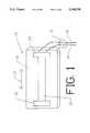
- FIG. 1is a view of the strain gauge sensor as packaged for external use
- FIG. 2is a view of the substrate after application of the highly conductive path
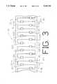
- FIG. 3is a view similar to FIG. 2 showing positioning of the resistive areas
- FIG. 4is a view similar to FIG. 3 showing the location of the die cuts
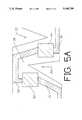
- FIG. 5Ais a closeup view showing how the resistive area is deformed as the sensor substrate is partially extended
- FIG. 5Bis a schematic view of the sensor substrate as fully extended
- FIG. 6is a closeup view showing the terminal connector
- FIG. 7is an electrical schematic diagram of a typical monitoring circuit
- FIG. 8schematically shows the strain gauge in a typical application for monitoring an apnea patient:
- FIG. 9shows a basic sensor packaged for implantable use.
- FIG. 1is a simplified view of strain gauge 10 as packaged for disposable use in an acute external application such as apnea monitoring.
- the ends of basic sensor structure 20are applied to acute substrate 18 using adhesive bonds 22 and 24.
- Acute substrate 18is chosen to be soft and flexible. Various polymer foams are readily available for this use. It must be elastic in the longitudinal dimension, such that it is free to stretch and compress in the directions shown by arrow 26.
- Acute substrate 18may be removably attached to an apnea patient (not shown) using a belt, adhesive, or other convenient means.
- basic sensor structure 20is fixedly attached to acute substrate 18, it must also be extendible and compressible in the directions of arrow 26. To permit some compression, basic sensor structure 20 must be placed under some slight tension at the time of fixation to acute substrate 18. This will become apparent from the discussion below concerning the construction of basic sensor structure 20.
- basic sensor structure 20having the resistive elements which change with mechanical movement is placed adjacent to acute substrate 18.
- the surface of basic sensor structure 20 facing away from the patientcontains only a return circuit path.
- This conductor of low resistivitypermits both wire 14 and wire 16, comprising cable 12, to exit basic sensor structure 20 from the same side of basic sensor structure 20. Note that this means that basic sensor structure 20 is a multi-sided substrate.
- FIG. 2shows the initial steps of fabricating basic sensor structure 20.
- Sensor substrate 28is a flexible insulator.
- the flexibilitypermits basic sensor structure 20 to readily conform to the body of the patient after attachment to acute substrate 18.
- sensor substrate 28is not elastic in the longitudinal dimension. This property ensures that as basic sensor structure 20 is stretched and compressed, the stretching and compression will occur primarily at specific desired areas.
- a serpentine conductorcomprising segments 30, 32, 34, 36, 38, 40, 42, 44, 46, 50, 52, 54, 56, 58, and 60, is placed on one surface of sensor substrate 28.
- these segmentsare placed using a silk screening process of conductive ink.
- the preferred conductive ink for this purposehas a high silver content to make each segment highly conductive.
- the segmentsmay be deposited using any other convenient process.
- Breaks 62, 64, 66, 68, 70, 72, 74, 76, 78, 80, 82, 84, 86, 88, and 90separate each of the respective segments and represent breaks in the conductive path of the serpentine conductor. It is important that a high proportion of the total length of the serpentine path be highly conductive and that the sum total of the longitudinal dimension of the breaks be small in relation thereto.
- FIG. 3is similar to FIG. 2 after the addition of the areas of resistive material.
- a layer of graphite or other relatively high resistance materialis deposited to complete the electrical contact between adjacent ones of segments 30-60. This results in resistive pads 91, 92, 94, 96, 98, 100, 102, 104, 106, 108, 110, 112, 114, 116, and 118.
- resistive pads 91, 92, 94, 96, 98, 100, 102, 104, 106, 108, 110, 112, 114, 116, and 118At this point in the fabrication process, there is electrical conductivity from segment 30 to segment 60 through the serpentine conductor. Most of the linear distance between segment 30 and segment 60 is via the highly conductive segments, however, even though the total linear distance of breaks 62-90 is small, the relative resistance of the breaks is high and the overall impedance of basic sensing structure 20 is high.
- FIG. 4is a view similar to FIG. 3 after die cutting. Because sensor substrate 28 is inelastic, it would not appreciably stretch or compress in the longitudinal direction with mechanical motion. To permit the desired change in longitudinal dimension, sensor substrate 28 is die cut along cut lines 120, 122, 124, 126, 128, 130, 132, 134, 136, 138, 140, 142, 144, and 146. Sensor substrate 28 appears to stretch after these cuts are made as a result of the deformation of sensor substrate 28 under longitudinal tension.
- Cut lines 120-146are positioned to terminate just adjacent to a corresponding one of the breaks 62-90 as shown. This ensures that as sensor substrate 28 is "stretched" (i.e. deformed under longitudinal tension and extended in length); the major deformation in the form of a compression of the highly resistive element occurs at the corresponding one of the breaks 62-90. This deformation of the graphite providing conductivity across each break produces the resistance change which is measured electrically. The amount of such resistance change indicates the extent of deformation and therefore the amount of longitudinal tension or extension in length.
- FIG. 5Ais a closeup view of the operation of the strain gauge at two breaks under partial extension of the basic sensor. All referenced elements are as previously described. As longitudinal tension is increased, cuts 134 and 122 are forced open. This imparts a twisting and bending force on resistive pads 92 and 94, respectively. The resulting change in resistance of these and the remaining resistive pads changes the direct current resistance of the strain gauge in accordance with the degree of longitudinal extension.
- FIG. 5Bis a schematic view of the basic sensor as more fully extended. Further longitudinal tension (see also FIG. 5A) increases the twisting force and further opens the breaks. This continues to elongate the basic sensor.
- FIG. 6is a closeup view of the end of basic sensor structure 20 showing terminal connections.
- the electrical couplingis provided by sliding connector 157 over the corresponding end of basic sensor 20 as shown.
- wire 16is electrically coupled to segment 150
- wire 14is electrically coupled to segment 152.
- Feed through 156consists of a rivet or other common means to establish electrical contact with the return path on the opposite side of sensor substrate 28 (see above).
- Wires 14 and 16are electrically coupled to sliding connector 157 by soldering or other common means.
- FIG. 7is an electrical schematic diagram of a circuit used to monitor resistance variations produced by the basic sensor 20.
- the circuitis essentially a constant current source in which the varying voltage is observed for changes in sensor resistance.
- Constant current device 202is supplied input power between power input 208 and ground.
- the current levelis set by resistor 204.
- the negative return to groundis via a resistance bridge consisting of a 20 k ohm series resistor 206 and basic sensor 20, also nominally 20 k, (not shown in this figure) through wires 14 and 16 and sliding connector 157.
- Parallel capacitor 210decouples unwanted high frequencies.
- the voltage signal representing variations in load experienced by constant current device 202is amplified by operational amplifier 218 as transferred differentially by series resistors 220 and 212. Differential amplification subtracts out the D.C. voltage allowing high amplification of the small varying voltages without saturating the amplifier. Capacitors 214 and 224 decouple unwanted high frequencies.
- Output 226 of operational amplifieris an amplified signal with respect to ground which varies as the resistance of basic sensor 20. This signal may be appropriately displayed in linear fashion by a meter or scope to show degree of change of length of basic sensor 20. Alternatively, output 226 may be presented to a bistable device for use as a threshold monitor.
- FIG. 8is a schematic view of a typical application of strain gauge 10 to infant apnea patient 160.
- Strain gauge 10is attached to abdomen or thorax 162 of patient 160 as discussed above. Wires 14 and 16 are coupled to electrical circuitry 200 (see also FIG. 7). As patient 160 breathes, abdomen or thorax 162 expands and contracts. This extends and compresses strain gauge 10 causing changes in the voltage measured by electrical circuitry 200.
- the monitorhas a threshold indicator 164 which lights upon an insufficient amount of mechanical activity over a predetermined period of time. This deficiency in mechanical activity is presumed to be central sleep apnea thus necessitating immediate attention to infant apnea patient 160.
- FIG. 9is a conceptual view of implantable strain gauge 300 according to the present invention as packaged by chronic implantable use.
- the deviceconsists primarily of strain gauge 20 encapsulated within an outer protective sheath 302 preferably made of silicone rubber or other elastic biocompatible material.
- the packageis completely sealed at ends 304 and 310 against the ingress of bodily fluids.
- the ends of strain gauge 20must be fixedly attached to the elastic substrate. In this embodiment, it is convenient to adhesively attach the ends at 306 and 308. In this manner strain gauge 20 is caused to extend and compress along with outer protective sheath 302 in the direction of arrow 312.
- the remaining referenced elementsare as previously described.
Landscapes
- Health & Medical Sciences (AREA)
- Physics & Mathematics (AREA)
- Life Sciences & Earth Sciences (AREA)
- General Physics & Mathematics (AREA)
- Biomedical Technology (AREA)
- Molecular Biology (AREA)
- Dentistry (AREA)
- Biophysics (AREA)
- Pathology (AREA)
- Engineering & Computer Science (AREA)
- Physiology (AREA)
- Heart & Thoracic Surgery (AREA)
- Medical Informatics (AREA)
- Oral & Maxillofacial Surgery (AREA)
- Surgery (AREA)
- Animal Behavior & Ethology (AREA)
- General Health & Medical Sciences (AREA)
- Public Health (AREA)
- Veterinary Medicine (AREA)
- Measurement Of The Respiration, Hearing Ability, Form, And Blood Characteristics Of Living Organisms (AREA)
- Measurement Of Length, Angles, Or The Like Using Electric Or Magnetic Means (AREA)
Abstract
Description
Claims (10)
Priority Applications (1)
| Application Number | Priority Date | Filing Date | Title |
|---|---|---|---|
| US07/751,507US5168759A (en) | 1991-08-29 | 1991-08-29 | Strain gauge for medical applications |
Applications Claiming Priority (1)
| Application Number | Priority Date | Filing Date | Title |
|---|---|---|---|
| US07/751,507US5168759A (en) | 1991-08-29 | 1991-08-29 | Strain gauge for medical applications |
Publications (1)
| Publication Number | Publication Date |
|---|---|
| US5168759Atrue US5168759A (en) | 1992-12-08 |
Family
ID=25022294
Family Applications (1)
| Application Number | Title | Priority Date | Filing Date |
|---|---|---|---|
| US07/751,507Expired - Fee RelatedUS5168759A (en) | 1991-08-29 | 1991-08-29 | Strain gauge for medical applications |
Country Status (1)
| Country | Link |
|---|---|
| US (1) | US5168759A (en) |
Cited By (35)
| Publication number | Priority date | Publication date | Assignee | Title |
|---|---|---|---|---|
| US6079277A (en)* | 1997-12-12 | 2000-06-27 | The Research Foundation Of State University Of New York | Methods and sensors for detecting strain and stress |
| US20060095091A1 (en)* | 2004-11-02 | 2006-05-04 | Medtronic, Inc. | Apparatus for data retention in an implantable medical device |
| US20060094972A1 (en)* | 2004-11-02 | 2006-05-04 | Medtronic, Inc. | Techniques for user-activated data retention in an implantable medical device |
| US20060135881A1 (en)* | 2004-12-17 | 2006-06-22 | Medtronic, Inc. | System and method for monitoring or treating nervous system disorders |
| US20060195039A1 (en)* | 2004-11-02 | 2006-08-31 | Medtronic, Inc. | Clustering with combined physiological signals |
| US20060211951A1 (en)* | 2002-05-29 | 2006-09-21 | Zoran Milijasevic | Implantable bladder sensor |
| US20060235489A1 (en)* | 2004-11-02 | 2006-10-19 | Medtronic, Inc. | Patient event marking in combination with physiological signals |
| US20070239060A1 (en)* | 2004-12-17 | 2007-10-11 | Medtronic, Inc. | System and method for regulating cardiac triggered therapy to the brain |
| US20070239230A1 (en)* | 2004-12-17 | 2007-10-11 | Medtronic, Inc. | System and method for regulating cardiac triggered therapy to the brain |
| US20070239054A1 (en)* | 2004-12-17 | 2007-10-11 | Medtronic, Inc. | System and method for monitoring or treating nervous system disorders |
| US20070238939A1 (en)* | 2004-12-17 | 2007-10-11 | Medtronic, Inc. | System and method for monitoring or treating nervous system disorders |
| US20070255155A1 (en)* | 2006-04-27 | 2007-11-01 | Medtronic, Inc. | Method and system for loop recording with overlapping events |
| US20070255531A1 (en)* | 2006-04-27 | 2007-11-01 | Medtronic, Inc. | Peak data retention of signal data in an implantable medical device |
| US20070260147A1 (en)* | 2004-12-17 | 2007-11-08 | Medtronic, Inc. | System and method for monitoring cardiac signal activity in patients with nervous system disorders |
| US20070260289A1 (en)* | 2004-12-17 | 2007-11-08 | Medtronic, Inc. | System and method for using cardiac events to trigger therapy for treating nervous system disorders |
| US20070265677A1 (en)* | 2004-12-17 | 2007-11-15 | Giftakis Jonathon E | System and method for utilizing brain state information to modulate cardiac therapy |
| US20070265536A1 (en)* | 2004-12-17 | 2007-11-15 | Giftakis Jonathon E | System and method for segmenting a cardiac signal based on brain stimulation |
| US20080269842A1 (en)* | 2007-04-27 | 2008-10-30 | Giftakis Jonathon E | Implantable medical device for treating neurological conditions with an initially disabled cardiac therapy port and leadless ECG sensing |
| US7764988B2 (en) | 2006-04-27 | 2010-07-27 | Medtronic, Inc. | Flexible memory management scheme for loop recording in an implantable device |
| US20100274072A1 (en)* | 2003-09-19 | 2010-10-28 | Creasey Graham H | Sphincteric control system |
| US8108038B2 (en) | 2004-12-17 | 2012-01-31 | Medtronic, Inc. | System and method for segmenting a cardiac signal based on brain activity |
| US8214035B2 (en) | 2004-12-17 | 2012-07-03 | Medtronic, Inc. | System and method for utilizing brain state information to modulate cardiac therapy |
| US20130165809A1 (en)* | 2010-07-29 | 2013-06-27 | Digisense Ltd. | Monitoring physiological condition of a subject |
| EP1947436A4 (en)* | 2005-09-12 | 2014-04-02 | Univ Tokyo | TOUCH SENSOR MODULE AND METHOD FOR PACKAGING TOUCH SENSOR |
| JP2014512197A (en)* | 2011-01-25 | 2014-05-22 | アペリス・ホールディングス,エルエルシー | Apparatus and method for assisting breathing |
| CN105222933A (en)* | 2015-09-22 | 2016-01-06 | 上海斐讯数据通信技术有限公司 | The stress monitoring method of a kind of electronic equipment and application thereof |
| CN106595915A (en)* | 2016-11-30 | 2017-04-26 | 华中科技大学 | Method for manufacturing flexible resistance strain gauge through friction mode |
| US10485585B2 (en) | 2011-06-16 | 2019-11-26 | Clifford T. Solomon | Skull clamp system with pressure limiting and alarm systems |
| JP2020180872A (en)* | 2019-04-25 | 2020-11-05 | 公立大学法人大阪 | Strain sensor and its manufacturing method |
| US10945659B1 (en) | 2015-03-16 | 2021-03-16 | Dp Technologies, Inc. | Dual sleep monitor |
| US11793455B1 (en) | 2018-10-15 | 2023-10-24 | Dp Technologies, Inc. | Hardware sensor system for controlling sleep environment |
| US11850068B2 (en) | 2019-11-27 | 2023-12-26 | International Business Machines Corporation | Modular sensing unit |
| US11883188B1 (en)* | 2015-03-16 | 2024-01-30 | Dp Technologies, Inc. | Sleep surface sensor based sleep analysis system |
| US11963792B1 (en) | 2014-05-04 | 2024-04-23 | Dp Technologies, Inc. | Sleep ecosystem |
| US12315615B2 (en) | 2012-03-06 | 2025-05-27 | Dp Technologies, Inc. | Optimal sleep phase selection system |
Citations (3)
| Publication number | Priority date | Publication date | Assignee | Title |
|---|---|---|---|---|
| US3118301A (en)* | 1964-01-21 | Strain gage for high elongation | ||
| US3782182A (en)* | 1971-04-29 | 1974-01-01 | Vishay Intertechnology Inc | Strain multiplier |
| US5079535A (en)* | 1990-09-11 | 1992-01-07 | Case Western Reserve University | Strain gauge and method of making and using the same |
- 1991
- 1991-08-29USUS07/751,507patent/US5168759A/ennot_activeExpired - Fee Related
Patent Citations (3)
| Publication number | Priority date | Publication date | Assignee | Title |
|---|---|---|---|---|
| US3118301A (en)* | 1964-01-21 | Strain gage for high elongation | ||
| US3782182A (en)* | 1971-04-29 | 1974-01-01 | Vishay Intertechnology Inc | Strain multiplier |
| US5079535A (en)* | 1990-09-11 | 1992-01-07 | Case Western Reserve University | Strain gauge and method of making and using the same |
Cited By (81)
| Publication number | Priority date | Publication date | Assignee | Title |
|---|---|---|---|---|
| US6079277A (en)* | 1997-12-12 | 2000-06-27 | The Research Foundation Of State University Of New York | Methods and sensors for detecting strain and stress |
| US20060211951A1 (en)* | 2002-05-29 | 2006-09-21 | Zoran Milijasevic | Implantable bladder sensor |
| US20100274072A1 (en)* | 2003-09-19 | 2010-10-28 | Creasey Graham H | Sphincteric control system |
| US20060235489A1 (en)* | 2004-11-02 | 2006-10-19 | Medtronic, Inc. | Patient event marking in combination with physiological signals |
| US9259177B2 (en) | 2004-11-02 | 2016-02-16 | Medtronic, Inc. | Techniques for data retention upon detection of an event in an implantable medical device |
| US20060094972A1 (en)* | 2004-11-02 | 2006-05-04 | Medtronic, Inc. | Techniques for user-activated data retention in an implantable medical device |
| US10201305B2 (en) | 2004-11-02 | 2019-02-12 | Medtronic, Inc. | Apparatus for data retention in an implantable medical device |
| US10111613B2 (en) | 2004-11-02 | 2018-10-30 | Medtronic, Inc. | Methods for data retention in an implantable medical device |
| US20060195039A1 (en)* | 2004-11-02 | 2006-08-31 | Medtronic, Inc. | Clustering with combined physiological signals |
| US20060094971A1 (en)* | 2004-11-02 | 2006-05-04 | Medtronic, Inc. | Techniques for data retention upon detection of an event in an implantable medical device |
| US20060094970A1 (en)* | 2004-11-02 | 2006-05-04 | Medtronic, Inc. | Techniques for selective channel processing and data retention in an implantable medical device |
| US20060287691A1 (en)* | 2004-11-02 | 2006-12-21 | Medtronic, Inc. | Methods for data retention in an implantable medical device |
| US20060095092A1 (en)* | 2004-11-02 | 2006-05-04 | Medtronic, Inc. | Techniques for data reporting in an implantable medical device |
| US8768446B2 (en) | 2004-11-02 | 2014-07-01 | Medtronic, Inc. | Clustering with combined physiological signals |
| US8478417B2 (en) | 2004-11-02 | 2013-07-02 | Medtronic, Inc. | Techniques for data reporting in an implantable medical device |
| US8224431B2 (en) | 2004-11-02 | 2012-07-17 | Medtronic, Inc. | Techniques for selective channel processing and data retention in an implantable medical device |
| US8108033B2 (en) | 2004-11-02 | 2012-01-31 | Medtronic, Inc. | Techniques for data retention upon detection of an event in an implantable medical device |
| US20060095091A1 (en)* | 2004-11-02 | 2006-05-04 | Medtronic, Inc. | Apparatus for data retention in an implantable medical device |
| US8024029B2 (en) | 2004-11-02 | 2011-09-20 | Medtronic, Inc. | Techniques for user-activated data retention in an implantable medical device |
| US20110166471A1 (en)* | 2004-11-02 | 2011-07-07 | Medtronic, Inc. | Patient Event Marking in Combination with Physiological Signals |
| US7917199B2 (en) | 2004-11-02 | 2011-03-29 | Medtronic, Inc. | Patient event marking in combination with physiological signals |
| US8068911B2 (en) | 2004-12-17 | 2011-11-29 | Medtronic, Inc. | System and method for regulating cardiopulmonary triggered therapy to the brain |
| US20070239054A1 (en)* | 2004-12-17 | 2007-10-11 | Medtronic, Inc. | System and method for monitoring or treating nervous system disorders |
| US20060135881A1 (en)* | 2004-12-17 | 2006-06-22 | Medtronic, Inc. | System and method for monitoring or treating nervous system disorders |
| US20060136006A1 (en)* | 2004-12-17 | 2006-06-22 | Medtronic, Inc. | System and method for regulating cardiac triggered therapy to the brain |
| US20070239060A1 (en)* | 2004-12-17 | 2007-10-11 | Medtronic, Inc. | System and method for regulating cardiac triggered therapy to the brain |
| US20070239230A1 (en)* | 2004-12-17 | 2007-10-11 | Medtronic, Inc. | System and method for regulating cardiac triggered therapy to the brain |
| US8761868B2 (en) | 2004-12-17 | 2014-06-24 | Medtronic, Inc. | Method for monitoring or treating nervous system disorders |
| US8744562B2 (en) | 2004-12-17 | 2014-06-03 | Medtronic, Inc. | Method for monitoring or treating nervous system disorders |
| US20070265536A1 (en)* | 2004-12-17 | 2007-11-15 | Giftakis Jonathon E | System and method for segmenting a cardiac signal based on brain stimulation |
| US7865244B2 (en) | 2004-12-17 | 2011-01-04 | Medtronic, Inc. | System and method for regulating cardiopulmonary triggered therapy to the brain |
| US20070265677A1 (en)* | 2004-12-17 | 2007-11-15 | Giftakis Jonathon E | System and method for utilizing brain state information to modulate cardiac therapy |
| US20110087082A1 (en)* | 2004-12-17 | 2011-04-14 | Medtronic, Inc. | Method for Monitoring or Treating Nervous System Disorders |
| US20110105913A1 (en)* | 2004-12-17 | 2011-05-05 | Medtronic, Inc. | Method for Monitoring or Treating Nervous System Disorders |
| US7945316B2 (en) | 2004-12-17 | 2011-05-17 | Medtronic, Inc. | System and method for monitoring or treating nervous system disorders |
| US20070260289A1 (en)* | 2004-12-17 | 2007-11-08 | Medtronic, Inc. | System and method for using cardiac events to trigger therapy for treating nervous system disorders |
| US8485979B2 (en) | 2004-12-17 | 2013-07-16 | Medtronic, Inc. | System and method for monitoring or treating nervous system disorders |
| US20070260147A1 (en)* | 2004-12-17 | 2007-11-08 | Medtronic, Inc. | System and method for monitoring cardiac signal activity in patients with nervous system disorders |
| US8041419B2 (en) | 2004-12-17 | 2011-10-18 | Medtronic, Inc. | System and method for monitoring or treating nervous system disorders |
| US8041418B2 (en) | 2004-12-17 | 2011-10-18 | Medtronic, Inc. | System and method for regulating cardiac triggered therapy to the brain |
| US20080033490A1 (en)* | 2004-12-17 | 2008-02-07 | Medtronic, Inc. | System and method for regulating cardiopulmonary triggered therapy to the brain |
| US8108038B2 (en) | 2004-12-17 | 2012-01-31 | Medtronic, Inc. | System and method for segmenting a cardiac signal based on brain activity |
| US20070238939A1 (en)* | 2004-12-17 | 2007-10-11 | Medtronic, Inc. | System and method for monitoring or treating nervous system disorders |
| US8108046B2 (en) | 2004-12-17 | 2012-01-31 | Medtronic, Inc. | System and method for using cardiac events to trigger therapy for treating nervous system disorders |
| US8112148B2 (en) | 2004-12-17 | 2012-02-07 | Medtronic, Inc. | System and method for monitoring cardiac signal activity in patients with nervous system disorders |
| US8112153B2 (en) | 2004-12-17 | 2012-02-07 | Medtronic, Inc. | System and method for monitoring or treating nervous system disorders |
| US8209019B2 (en) | 2004-12-17 | 2012-06-26 | Medtronic, Inc. | System and method for utilizing brain state information to modulate cardiac therapy |
| US8209009B2 (en) | 2004-12-17 | 2012-06-26 | Medtronic, Inc. | System and method for segmenting a cardiac signal based on brain stimulation |
| US8214035B2 (en) | 2004-12-17 | 2012-07-03 | Medtronic, Inc. | System and method for utilizing brain state information to modulate cardiac therapy |
| EP1947436A4 (en)* | 2005-09-12 | 2014-04-02 | Univ Tokyo | TOUCH SENSOR MODULE AND METHOD FOR PACKAGING TOUCH SENSOR |
| US20080235469A1 (en)* | 2006-04-27 | 2008-09-25 | Medtronic, Inc. | Peak Data Retention of Signal Data In An Implantable Medical Device |
| US20070255531A1 (en)* | 2006-04-27 | 2007-11-01 | Medtronic, Inc. | Peak data retention of signal data in an implantable medical device |
| US20070255155A1 (en)* | 2006-04-27 | 2007-11-01 | Medtronic, Inc. | Method and system for loop recording with overlapping events |
| US7765088B2 (en) | 2006-04-27 | 2010-07-27 | Medtronic, Inc. | Peak data retention of signal data in an implantable medical device |
| US7764988B2 (en) | 2006-04-27 | 2010-07-27 | Medtronic, Inc. | Flexible memory management scheme for loop recording in an implantable device |
| US7610083B2 (en) | 2006-04-27 | 2009-10-27 | Medtronic, Inc. | Method and system for loop recording with overlapping events |
| US7359837B2 (en) | 2006-04-27 | 2008-04-15 | Medtronic, Inc. | Peak data retention of signal data in an implantable medical device |
| US8000788B2 (en) | 2007-04-27 | 2011-08-16 | Medtronic, Inc. | Implantable medical device for treating neurological conditions including ECG sensing |
| US9014804B2 (en) | 2007-04-27 | 2015-04-21 | Medtronic, Inc. | Implantable medical device for treating neurological conditions including ECG sensing |
| US20080269842A1 (en)* | 2007-04-27 | 2008-10-30 | Giftakis Jonathon E | Implantable medical device for treating neurological conditions with an initially disabled cardiac therapy port and leadless ECG sensing |
| US20130165809A1 (en)* | 2010-07-29 | 2013-06-27 | Digisense Ltd. | Monitoring physiological condition of a subject |
| JP2024010176A (en)* | 2011-01-25 | 2024-01-23 | アペリス・ホールディングス,エルエルシー | Devices and methods for assisting breathing |
| US12329716B2 (en) | 2011-01-25 | 2025-06-17 | Liberate Medical, Llc | Apparatus and methods for assisting breathing |
| JP2017094099A (en)* | 2011-01-25 | 2017-06-01 | アペリス・ホールディングス,エルエルシー | Apparatus and method for assisting breathing |
| JP2014512197A (en)* | 2011-01-25 | 2014-05-22 | アペリス・ホールディングス,エルエルシー | Apparatus and method for assisting breathing |
| JP2022002732A (en)* | 2011-01-25 | 2022-01-11 | アペリス・ホールディングス,エルエルシー | Devices and methods to support breathing |
| US11529283B2 (en) | 2011-01-25 | 2022-12-20 | Apellis Holdings, Llc | Apparatus and methods for assisting breathing |
| US10485585B2 (en) | 2011-06-16 | 2019-11-26 | Clifford T. Solomon | Skull clamp system with pressure limiting and alarm systems |
| US12315615B2 (en) | 2012-03-06 | 2025-05-27 | Dp Technologies, Inc. | Optimal sleep phase selection system |
| US11963792B1 (en) | 2014-05-04 | 2024-04-23 | Dp Technologies, Inc. | Sleep ecosystem |
| US11883188B1 (en)* | 2015-03-16 | 2024-01-30 | Dp Technologies, Inc. | Sleep surface sensor based sleep analysis system |
| US10945659B1 (en) | 2015-03-16 | 2021-03-16 | Dp Technologies, Inc. | Dual sleep monitor |
| CN105222933A (en)* | 2015-09-22 | 2016-01-06 | 上海斐讯数据通信技术有限公司 | The stress monitoring method of a kind of electronic equipment and application thereof |
| CN106595915A (en)* | 2016-11-30 | 2017-04-26 | 华中科技大学 | Method for manufacturing flexible resistance strain gauge through friction mode |
| US11793455B1 (en) | 2018-10-15 | 2023-10-24 | Dp Technologies, Inc. | Hardware sensor system for controlling sleep environment |
| US12343137B1 (en) | 2018-10-15 | 2025-07-01 | Dp Technologies, Inc. | Hardware sensor system for controlling sleep environment |
| US12048529B1 (en) | 2018-10-15 | 2024-07-30 | Dp Technologies, Inc. | Hardware sensor system for improved sleep detection |
| US12251214B1 (en) | 2018-10-15 | 2025-03-18 | Dp Technologies, Inc. | Sleep detection and analysis system |
| JP2020180872A (en)* | 2019-04-25 | 2020-11-05 | 公立大学法人大阪 | Strain sensor and its manufacturing method |
| JP7321502B2 (en) | 2019-04-25 | 2023-08-07 | 公立大学法人大阪 | Strain sensor and manufacturing method thereof |
| US11850068B2 (en) | 2019-11-27 | 2023-12-26 | International Business Machines Corporation | Modular sensing unit |
Similar Documents
| Publication | Publication Date | Title |
|---|---|---|
| US5168759A (en) | Strain gauge for medical applications | |
| US3268845A (en) | Respiration and movement transducer | |
| CA1166701A (en) | Vital signs monitor | |
| US6865409B2 (en) | Surface electromyographic electrode assembly | |
| US20200225101A1 (en) | Core-shell nanofiber textiles for strain sensing, and methods of their manufacture | |
| US4426884A (en) | Flexible force sensor | |
| US8996100B2 (en) | Monitoring system comprising electrodes with projections | |
| EP0328558B1 (en) | Tubular pressure transducer | |
| US20050096513A1 (en) | Wearable biomonitor with flexible thinned integrated circuit | |
| US20020180605A1 (en) | Wearable biomonitor with flexible thinned integrated circuit | |
| US5289827A (en) | Uterine contraction sensing method | |
| US20040236202A1 (en) | Expandable strap for use in electrical impedance tomography | |
| EP0615424A1 (en) | Sensor apparatus | |
| AU2008300320A1 (en) | A sensor for intravascular measurements within a living body | |
| EP1451873A2 (en) | Wearable biomonitor with flexible thinned integrated circuit | |
| WO2021055496A1 (en) | Wearable strain sensor for measuring respiration rate and volume | |
| US5207230A (en) | Spiral sensor | |
| US20090247858A1 (en) | "bulls-eye" surface electromyographic electrode assembly | |
| JP4045344B2 (en) | Body motion detection sensor and body motion monitoring system using the same | |
| JPH0630914A (en) | Organismic signal detector | |
| KR20190052636A (en) | Respiratory monitoring system | |
| US8209031B1 (en) | Implantable lead for measuring physiologic information | |
| KR20230088073A (en) | Disposable dry flexible pad for wearable and continuous egc | |
| Bhat et al. | Piezoelectric sensor for foot pressure management | |
| US20230113963A1 (en) | Neuromuscular transmission monitoring system and kinemyography sensor |
Legal Events
| Date | Code | Title | Description |
|---|---|---|---|
| AS | Assignment | Owner name:EDENTEC A CORP. OF MN, MINNESOTA Free format text:ASSIGNMENT OF ASSIGNORS INTEREST.;ASSIGNOR:BOWMAN, BRUCE R.;REEL/FRAME:005825/0470 Effective date:19910821 | |
| REFU | Refund | Free format text:REFUND PROCESSED. MAINTENANCE FEE TENDERED TOO EARLY (ORIGINAL EVENT CODE: R161); ENTITY STATUS OF PATENT OWNER: LARGE ENTITY | |
| FEPP | Fee payment procedure | Free format text:PAYOR NUMBER ASSIGNED (ORIGINAL EVENT CODE: ASPN); ENTITY STATUS OF PATENT OWNER: LARGE ENTITY | |
| FPAY | Fee payment | Year of fee payment:4 | |
| FEPP | Fee payment procedure | Free format text:PAYER NUMBER DE-ASSIGNED (ORIGINAL EVENT CODE: RMPN); ENTITY STATUS OF PATENT OWNER: LARGE ENTITY Free format text:PAYOR NUMBER ASSIGNED (ORIGINAL EVENT CODE: ASPN); ENTITY STATUS OF PATENT OWNER: LARGE ENTITY | |
| FPAY | Fee payment | Year of fee payment:8 | |
| REMI | Maintenance fee reminder mailed | ||
| LAPS | Lapse for failure to pay maintenance fees | ||
| LAPS | Lapse for failure to pay maintenance fees | Free format text:PATENT EXPIRED FOR FAILURE TO PAY MAINTENANCE FEES (ORIGINAL EVENT CODE: EXP.); ENTITY STATUS OF PATENT OWNER: LARGE ENTITY | |
| STCH | Information on status: patent discontinuation | Free format text:PATENT EXPIRED DUE TO NONPAYMENT OF MAINTENANCE FEES UNDER 37 CFR 1.362 | |
| FP | Lapsed due to failure to pay maintenance fee | Effective date:20041208 |