US5168574A - System and method for switching between antennas in a radio frequency booster - Google Patents
System and method for switching between antennas in a radio frequency boosterDownload PDFInfo
- Publication number
- US5168574A US5168574AUS07/790,266US79026691AUS5168574AUS 5168574 AUS5168574 AUS 5168574AUS 79026691 AUS79026691 AUS 79026691AUS 5168574 AUS5168574 AUS 5168574A
- Authority
- US
- United States
- Prior art keywords
- antenna
- antennas
- signals
- selecting
- received
- Prior art date
- Legal status (The legal status is an assumption and is not a legal conclusion. Google has not performed a legal analysis and makes no representation as to the accuracy of the status listed.)
- Expired - Lifetime
Links
Images


Classifications
- H—ELECTRICITY
- H04—ELECTRIC COMMUNICATION TECHNIQUE
- H04B—TRANSMISSION
- H04B7/00—Radio transmission systems, i.e. using radiation field
- H04B7/14—Relay systems
- H04B7/15—Active relay systems
- H04B7/155—Ground-based stations
- H04B7/15528—Control of operation parameters of a relay station to exploit the physical medium
- H04B7/1555—Selecting relay station antenna mode, e.g. selecting omnidirectional -, directional beams, selecting polarizations
- H—ELECTRICITY
- H04—ELECTRIC COMMUNICATION TECHNIQUE
- H04B—TRANSMISSION
- H04B7/00—Radio transmission systems, i.e. using radiation field
- H04B7/24—Radio transmission systems, i.e. using radiation field for communication between two or more posts
- H04B7/26—Radio transmission systems, i.e. using radiation field for communication between two or more posts at least one of which is mobile
- H04B7/2603—Arrangements for wireless physical layer control
- H04B7/2606—Arrangements for base station coverage control, e.g. by using relays in tunnels
- H—ELECTRICITY
- H04—ELECTRIC COMMUNICATION TECHNIQUE
- H04W—WIRELESS COMMUNICATION NETWORKS
- H04W16/00—Network planning, e.g. coverage or traffic planning tools; Network deployment, e.g. resource partitioning or cells structures
- H04W16/24—Cell structures
- H04W16/26—Cell enhancers or enhancement, e.g. for tunnels, building shadow
Definitions
- the inventionpertains to boosters usable in cellular radiotelephone systems to improve intra-cell coverage. More particularly, the invention pertains to diversity reception of signals between the booster and the cell site, between the booster and another booster, or between the booster and a moveable cellular transceiver.
- cellular system cell-site designsdo not cover all the desired coverage areas due to anomalies of RF propagation. For example, a narrow depression in the terrain such as a ravine or along a road adjacent to a river bed may not have adequate signal coverage due to blockage from nearby terrain.
- Another examplewould be in an underground parking garage, or even in large office buildings where larger than normal signal attenuation would result in unacceptable signal levels. Furthermore, cell sites in some cellular systems are not located close enough together, thus resulting in poor coverage areas between the cells.
- a low cost alternative solution to this problemis to employ a cellular repeater or booster near the coverage area in question.
- a repeateris intended to retransmit the channels from a nearby (donor) cell into the problem area.
- the retransmitted channelscan then be received by appropriate moveable transceivers or mobile units in the area.
- transmissions from mobile units in the problem areacan be retransmitted by the booster such that they can be detected by the channel receivers at the donor cell site.
- One such boosteris disclosed in the commonly assigned patent application hereto, entitled Booster, U.S. Pat. No. 4,941,200 issued Jul. 10, 1991. That patent is hereby incorporated herein by reference.
- Cellular systemsemploy diversity reception of the signals from the mobile to the cell site to overcome the effects of multi-path fading.
- the signalsare amplified by a booster, the multi-path fading occurs on both the path from the mobile to booster and the path from the booster to the cell site.
- conventional methods of combining the diversity signalsmay not be effective.
- An effective diversity combiner designmust take into account the fact that the multi-path fading on each of these two paths has significantly different characteristics. This is because one path length is fixed and the other path length is changing rapidly due to vehicle movement. For example, the fades on the booster to cell path may experience typical fading durations of many seconds in contrast with the mobile to booster fading durations of a few milliseconds when the vehicle is moving.
- Switch diversity combiningis known.
- a receiverhas two antennas that are separated in space a distance sufficient to uncorrelate the multi-path fading of the signals on the antennas. Only one antenna is connected to the receiver at one time. If the received signal falls below a fixed threshold level, the receiver is switched to the other antenna. This switching algorithm is not optimum for cellular systems boosters.
- the threshold signal level for switching the antennasshould be a function of the received average signal for optimum switching.
- the multi-path fadingis very slow and may not change significantly during the duration of one call.
- the signal received by the cell site or booster receivermay vary rapidly because the booster receiving signals from the moveable transceiver has not removed all the multi-path fading caused by the transceiver to booster path.
- the diversity combinermust ignore these rapid fades and select the antenna having the best average signal level. At the same time the selection must be rapid compared to the duration of a call.
- An apparatus and method in accordance with the present inventionimplement an improved diversity receiving system.
- An apparatus in accordance with the present inventionincludes first and second antennas usable for receiving electro-magnetic signals. Circuitry coupled to the antennas senses incoming signal levels and selects, in accordance with a predetermined criterion, which of the antennas is to be used.
- the circuitryWhen the incoming signals are generated by a moving source, the circuitry repetitively samples a selected parameter value of the signals being detected off of the currently operative antenna. A running average of measured parameter values is formed.
- Antennasare switched if a current sampled signal parameter value falls below, by a predetermined amount, the previously developed running average.
- the antennasare switched if the parameter value of a current sensed signal falls below a predetermined threshold.
- the circuitryswitches antennas if a predetermined elapsed time has passed without a switch.
- the circuitryswitches antennas in the event that a predetermined time interval has elapsed and no switch has taken place. After the switch, a measured value of the selected parameter of the newly sensed signal is compared to the value of the same parameter sensed prior to switching antennas. In the event that the prior value exceeds the current value the antennas are again switched.
- FIG. 1is a block diagram of a portion of a cellular system that includes a booster in accordance with the present invention
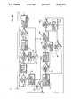
- FIGS. 2A-2D taken togetherare a flow diagram of various modes of operation of the booster of FIG. 1;
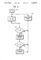
- FIG. 3is a flow diagram illustrating the operation of the booster of FIG. 1 during reception on the mobile to booster link;
- FIG. 4is a flow diagram illustrating an alternative mode of operation of the booster of FIG. 1 during reception on the booster to cell site link or the booster to booster link.
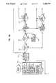
- FIG. 1illustrates a system 10 in accordance with the present invention.
- the system 10includes a fixed cell site 12 of a conventional variety used in connection with cellular mobile radio telephone service.
- the cell site 12includes a transmitting and receiving antenna 14.
- a booster 16is illustrated in FIG. 1 in bidirectional communication with the cell site 12 and a mobile unit M.
- the booster 16includes a directional transmit and receive antenna 18 which is used to transmit signals to and receive signals from the cell site 12.
- the booster 16also includes a second antenna 20 for transmitting signals to and receiving signals from the mobile unit M.
- the antenna 20can be, but need not be, a directional antenna.
- the booster 16can repeat both voice and control channels in connection with a cellular mobile transmission.
- the repeated channelcan be repeated at the same frequency as received. Alternately, the booster 16 can shift the transmitted frequency from the received frequency.
- the booster 16includes a plurality of intermediate frequency communication paths such as channel paths 22-30 which provide for transmission of five channels of control or audio in parallel between the mobile unit M and the cell site 12.
- the booster 16also includes a plurality of cell site to mobile communication paths 32-40 for transmitting five channels of control or audio between cell site 12 and the mobile M.
- Each of the intermediate channels 22-30, and 32-40is identical. Each shifts an incoming frequency down to a predetermined intermediate frequency for filtering (each includes a 30 K Hz bandwidth filter) for amplification. Each amplified intermediate frequency signal is then shifted up to a predetermined transmission frequency.
- Channel 21has the same structure as do each of channels 22-30. Channels 22-30 and 32-40 are used for repeating incoming signals in accordance with a predetermined interior discussed subsequently. Channel 21 is used only for measuring incoming signals from mobil M and for transmitting hand-off messages to the mobile M.
- Signals from the cell site 12 transmitted to the booster 16 and detected at antenna 18pass through duplexer 50 and enter multi-coupler 52.
- the multi-coupler 52provides RF amplification of low level signals.
- Output from the multi-coupler 52, on lines 52a-e,provides input to the communication paths 32-40 which, as discussed subsequently, are implemented as intermediate frequency transmission paths.
- Output from each of the paths 32-40is amplified in RF power output amplifiers 54a-e.
- Amplified outputs from the amplifiers 54a-eare combined in a high power lossless combiner 56.
- separate antennasmay be employed for each RF power amplifier, or a very high power linear amplifier using distortion cancelling techniques may be used with a single antenna.
- the output from the combiner 56, on a single line 56a,is coupled to a duplexer 58. Output from the duplexer 58 is then transmitted via the antenna 20 to the mobile M.
- Incoming signals received from the mobile unit M at the antenna 20are coupled via the duplexer 58 to multi-coupler 60.
- Outputs from the multi-coupler 60drive the intermediate frequency communication paths 22-30.
- Outputs from the paths 22-30are combined in a five way combiner 62.
- the combined output from the five way combiner 62is amplified in the linear amplifier 64.
- the output from the amplifier 64provides an input to the duplexer 50.
- Output from the duplexer 50is coupled via the directional antenna 18 to the cell site 12.
- the intermediate frequency communication paths 21-30 and 32-40operate under control of a stored program control unit 66.
- Mobiles that are driving into the area served by the booster 16are monitored for several scans thereof to determine the signal level trend before boosting or retransmission of the mobile is attempted. As a result, erroneous boosting of channels due to momentarily strong mobile signals can be minimized.
- a specific transmission pathcan be provided for the control channel of the cell site 12 to allow mobile call originations or terminations to be completed for those mobiles which are not currently active but which are in the vicinity of the booster 16.
- the transmission path for the control channelmay be purposely offset to provide F1-F2 repeater operation.
- an “action” threshold levelis provided to allow quick response in setting up a boosted transmission path for a new call. This "action" threshold level is generally higher than the minimum threshold level. A signal exceeding this level is flagged for immediate action at the end of a scan.
- the mobilewill transmit on the channel assigned by the cell site 12 for a maximum of five seconds without the presence of a correct supervisory audio tone being detected by the booster 16.
- a boosted transmission pathwill be placed on that channel within a couple of seconds. If the signal is below that threshold but above the minimum threshold, a boosted transmission path may be assigned within several seconds.
- Weaker mobile signals that approach the minimum thresholdwill generally be in an area where some coverage is provided directly from the cell site 12. This provides adequate time for the booster 16 to average the readings and determine that a new channel is to be boosted.
- Each of the intermediate frequency booster channels 21-30 and 32-40is implemented with microprocessor controlled step down and step up frequency synthesizers.
- the use of two frequency synthesizerspermits the offset of the control channel to another nearby control channel, as well as the offsetting of the voice channels.
- Channel 21is implemented using similar circuitry. The above comments also apply with respect to the transmission paths 32 through 40 which are used for the purpose of boosting signals from the cell site 12 to the mobile M.
- the stored program control unit 66includes an 8031 Intel microprocessor.
- the processorprovides overall control for the booster 16. It communicates with the other circuitry in the booster 16 via interface circuitry.
- the control unit 66also includes a 10 kilobit data demodulator and a 6 kHZ supervisory audio tone (SAT) demodulator.
- the demodulatorincludes circuitry for decoding the 10 kilobit data stream which is utilized in the cellular system and for measuring which of the SAT frequencies is being transponded by the cellular mobile unit such as the mobile unit M.
- the control unit 66is utilized for maintaining signal level history for processing purposes as well as for controlling the frequency synthesizers, such as the synthesizers in each intermediate frequency branch 21-30, and 32-40. It is also used for setting the signal gain through each path as well as for measuring the received signal levels on each channel and for carrying out diagnostic and parameter setting functions.
- FIGS. 2A-2Ddescribes the sequence of events that takes place in determining candidate channels for boosting. All the channels of the cell site 12 are scanned. If the measured signal level from a mobile on any of the cell site channels exceeds a minimum preset threshold and also has the correct SAT frequency, that channel number and its signal level are recorded. A running history of the signal levels of the various mobiles that are active is maintained in a table. At the end of each channel-set scan the data in the table are analyzed to rank the signals by level. A determination is then made as to which signals are to be boosted or retransmitted.
- the booster 10 of Figureincludes additional hardware to implement the diversity receiving capability in accordance with the present invention.
- a second antenna 19is provided for diversity reception and also usable for hand off message transmission to mobile units.
- the antenna 19is coupled to an antenna port of duplexer 59.
- Output from the duplexer 59is coupled to a receiver multicoupler 61.
- Parallel outputs from the receiver multicoupler 61 on a plurality of lines 61a through 61fare coupled by a plurality of radio frequency switches 63a through 63f to inputs to the intermediate frequency channels 21 through 30.
- Each of the radio frequency switchesreceives as a second input a corresponding signal line from the receiver multicoupler 60, lines 60a through 60f.
- Each of the radio frequency switchesfunctions under the control of a microprocessor contained in the corresponding intermediate frequency block, such as the block 21.
- a command line, such as 21a, from the microprocessorsignals the switch 63a as to which input is to be selected.
- the radio frequency switchescan each be implemented using forward or reverse biased PIN radio frequency switching diodes.
- intermediate frequency channel 21is coupled by a power amplifier 65 to the transmit input port of the duplexer 59.
- the amplifier 65can be used to provide handoff message signals for transmission to the moveable transceivers such as portable units or the mobile unit M in the vicinity of the booster 10.
- Intermediate frequency channel or path 21is used to either measure input signal levels from the moveable transceiver M or to transmit the previously noted handoff messages.
- the booster 10can also be equipped with a second directional antenna 17 directed toward the cell site 12.
- the second directional antenna 17can be used to implement an optional diversity function with respect to transmissions from the cell site 12.
- the antenna 17is coupled to an RF input port of multicoupler 51.
- Output from multicoupler 51, on a plurality of lines 51a through 51eis in turn coupled to an input of a respective one of a plurality of RF switches 53a through 53d.
- the switches 53a through 53dare identical to each of the switches 63a through 63f.
- Output from the multicoupler 52provides a second input to each of the switches 53a through 53f.
- Each of the radio frequency switches 53a through 53ffunctions under the control of a microprocessor in one of the respective intermediate frequency channels 32 through 40.
- a command line 40a between the intermediate frequency channel 40 and the radio frequency switch 53dcauses that switch to select an input from either multicoupler 52 or multicoupler 51.
- the booster 10can be used for the purpose of communicating with a second booster 10a.
- the booster 10acan in turn communicate directly with a mobile M'.
- the booster 10acan be implemented with two antennas, 19a, 20a for purposes of implementing diversity receiving function with respect to the mobile units, such as the mobile unit M'.
- a single antenna 18acan be implemented at the booster 10a for the purpose of communicating with the booster 10.
- a diversity antenna 17acorresponding to the diversity receiving antenna 17, can be implemented at the booster 10a for the purpose of providing a diversity receiving function therein with respect to transmissions from booster 10.
- fading on the mobile-booster pathis very rapid when the vehicle is moving but very slow when the vehicle is stationary.
- the fadingis very slow and may not change significantly during a given call. In this instance it is important to ignore any high speed fading and select an antenna having the best average signal value.
- FIG. 3is a flow diagram of the steps of a method in accordance with the present invention for antenna switching on the mobile to booster path.
- the method implemented in the flow diagram of FIG. 3is carried out by the respective controlling microprocessor in each of the intermediate frequency blocks 21-30.
- Such a microprocessorcan be implemented, for example, as a 63C05 type microprocessor.
- the respective microprocessorcalculates and stores, every few microseconds, typically 250 microseconds, the average signal received on the selected antenna 19 or 20. Signal values are averaged over a longer predetermined period of time, typically a half second or so. In addition the time interval since the last switch of antennas is recorded.
- a step 202the microprocessor determines whether or not the most recently sampled signal level off of the currently selected antenna is a predetermined number of dB below the precalculated average signal level. If so the antenna is switched. If antenna 19 had been selected antenna 20 will now be selected.
- the processordetermines whether or not the most recently measured signal value is less than a predetermined threshold value. If so the antennas are again interchanged. If not, the processor in a step 206 determines whether or not the time elapsed since the last interchange of antennas exceeds a predetermined period, typically one (1) second or so. If not the antennas are not interchanged and after a predetermined time interval, on the order of 250 ⁇ sec, the processor repeats the calculations.
- the microprocessorin a step 208 interchanges the antenna and resets the time duration indicator to zero (0).
- the processordetermines whether or not the present measured signal strength, after the antennas have been interchanged is greater than the previously measured signal strength. If so the newly selected antenna continues to be used. If not, the previously antenna is selected again.
- the method of FIG. 3operates independently in the control microprocessor of each of the channels 21-30. Hence, each such channel can independently switch between antenna 19 and antenna 20.
- FIG. 4is a flow diagram illustrating the steps carried out by the microprocessor in the immediate frequency blocks 21-30 when the booster 10 is repeating signals generated by another booster 10a.
- the method of FIG. 4illustrates steps carried out by channels 32-40 when repeating signals, received via antenna 17 or antenna 18, from the cell site 12.
- a longer predetermined period of time Tptypically 60 seconds or so, causes the microprocessor to select the antenna with the strongest signal every minute or so.
- Tscan be initially set to 60 in a step 214. Ts is compared to a preset value of Tp, on the order of 60 seconds, in a step 216. After a delay 218 on the order of 250 ⁇ sec, the process can be repeated.
- Each of the channels 21-30 or 32-40carries out the above described analysis and antenna switching function independently of every other channel.
Landscapes
- Engineering & Computer Science (AREA)
- Computer Networks & Wireless Communication (AREA)
- Signal Processing (AREA)
- Mobile Radio Communication Systems (AREA)
Abstract
Description
Claims (3)
Priority Applications (1)
| Application Number | Priority Date | Filing Date | Title |
|---|---|---|---|
| US07/790,266US5168574A (en) | 1987-08-03 | 1991-11-08 | System and method for switching between antennas in a radio frequency booster |
Applications Claiming Priority (2)
| Application Number | Priority Date | Filing Date | Title |
|---|---|---|---|
| US07/081,120US4941200A (en) | 1987-08-03 | 1987-08-03 | Booster |
| US07/790,266US5168574A (en) | 1987-08-03 | 1991-11-08 | System and method for switching between antennas in a radio frequency booster |
Related Parent Applications (1)
| Application Number | Title | Priority Date | Filing Date |
|---|---|---|---|
| US07/315,922ContinuationUS5065449A (en) | 1987-08-03 | 1989-02-24 | Booster diversity receiving system usable with cellular booster |
Publications (1)
| Publication Number | Publication Date |
|---|---|
| US5168574Atrue US5168574A (en) | 1992-12-01 |
Family
ID=26765229
Family Applications (1)
| Application Number | Title | Priority Date | Filing Date |
|---|---|---|---|
| US07/790,266Expired - LifetimeUS5168574A (en) | 1987-08-03 | 1991-11-08 | System and method for switching between antennas in a radio frequency booster |
Country Status (1)
| Country | Link |
|---|---|
| US (1) | US5168574A (en) |
Cited By (21)
| Publication number | Priority date | Publication date | Assignee | Title |
|---|---|---|---|---|
| US5377255A (en)* | 1992-07-14 | 1994-12-27 | Pcs Microcell International Inc. | RF repeaters for time division duplex cordless telephone systems |
| US5481571A (en)* | 1993-11-12 | 1996-01-02 | Pacific Communication Sciences, Inc. | Method and apparatus for switching between radio frequency circuits |
| US5603081A (en)* | 1993-11-01 | 1997-02-11 | Telefonaktiebolaget Lm Ericsson | Method for communicating in a wireless communication system |
| US5659879A (en)* | 1993-07-30 | 1997-08-19 | Alcatel N.V. | Method of covering shadow areas in a cellular mobile radio system and radio booster for implementing this method |
| US5737706A (en)* | 1995-08-03 | 1998-04-07 | Bell Atlantic Network Services, Inc. | Power system supporting CDPD operation |
| WO1999037041A1 (en)* | 1998-01-17 | 1999-07-22 | Shane Evans | Wireless telephone server system |
| US5987099A (en)* | 1992-10-16 | 1999-11-16 | Northern Telecom Limited | Low-power wireless system for telephone services |
| US6079367A (en)* | 1997-10-10 | 2000-06-27 | Dogwatch, Inc. | Animal training apparatus and method |
| US6088592A (en)* | 1996-03-25 | 2000-07-11 | Airnet Communications Corporation | Wireless system plan using in band-translators with diversity backhaul to enable efficient depolyment of high capacity base transceiver systems |
| US6157836A (en)* | 1995-06-07 | 2000-12-05 | Pacific Communication Sciences, Inc. | Portable communications and data terminal operating to optimize receipt of both incoming CDPD and AMPS messages |
| US6212176B1 (en) | 1992-10-05 | 2001-04-03 | Telefonaktiebolget Lm Ericsson (Publ) | Digital control channels having logical channels for multiple access radiocommunication |
| KR20020017202A (en)* | 2000-08-29 | 2002-03-07 | 손정수 | Mobile communications repeater |
| US6360088B1 (en)* | 1998-09-23 | 2002-03-19 | Ericsson Inc. | Antenna diversity switching system and method for selecting an antenna through a programmed evaluation |
| US6434395B1 (en)* | 1993-09-08 | 2002-08-13 | Pacific Communications Sciences, Inc. | Portable communications and data terminal having multiple modes of operation |
| US6577603B1 (en)* | 1996-10-09 | 2003-06-10 | Nokia Corporation | Method for determining speed of terminal, and receiver |
| EP1041735A3 (en)* | 1999-03-31 | 2004-01-21 | Harada Industry Co., Ltd. | Diversity device and diversity antenna |
| US6804491B1 (en)* | 1999-03-31 | 2004-10-12 | Matsushita Electric Industrial Co., Ltd. | Mobile communication system and repeater used in the mobile communication system |
| US20080089267A1 (en)* | 2006-09-21 | 2008-04-17 | Silvus Communications Systems, Inc. | Multi-antenna upgrade for a transceiver |
| WO2008150534A3 (en)* | 2007-06-01 | 2009-09-24 | Nextivity, Inc. | Short range booster and methods for boosting with multiple antennas |
| US9742481B1 (en)* | 2016-09-16 | 2017-08-22 | Amazon Technologies, Inc. | Antenna switching |
| US20190386758A1 (en)* | 2018-06-19 | 2019-12-19 | Nxp B.V. | Narrow band received signal strength indicator system |
Citations (12)
| Publication number | Priority date | Publication date | Assignee | Title |
|---|---|---|---|---|
| US3035169A (en)* | 1956-10-03 | 1962-05-15 | Gen Electric Co Ltd | Radio relay system with automatic channel selection based upon signal strength |
| US3182263A (en)* | 1962-11-14 | 1965-05-04 | Gossard William Herbert | Diversity reception system with correction for long-term fluctuations in signal strength |
| US3368151A (en)* | 1965-12-27 | 1968-02-06 | Navy Usa | Continuous antenna selection system |
| US4255816A (en)* | 1978-09-15 | 1981-03-10 | Threshold Technology, Inc. | Receiving apparatus having a plurality of antennas |
| US4317218A (en)* | 1980-03-26 | 1982-02-23 | General Electric Company | Arrangement for remote control of repeater stations |
| US4549311A (en)* | 1982-08-03 | 1985-10-22 | Motorola, Inc. | Method and apparatus for measuring the strength of a radio signal frequency |
| US4584713A (en)* | 1983-07-06 | 1986-04-22 | Motorola, Inc. | Signal quality steered diversity |
| US4696058A (en)* | 1983-12-06 | 1987-09-22 | Matsushita Electric Industrial Co., Ltd. | Diversity receiver |
| US4704734A (en)* | 1986-02-18 | 1987-11-03 | Motorola, Inc. | Method and apparatus for signal strength measurement and antenna selection in cellular radiotelephone systems |
| US4742568A (en)* | 1985-06-10 | 1988-05-03 | Nec Corporation | Receiver for antenna switching diversity systems |
| US4823398A (en)* | 1985-12-23 | 1989-04-18 | Kazuya Hashimoto | Diversity receiver |
| US4864642A (en)* | 1987-04-08 | 1989-09-05 | Pioneer Electronic Corporation | Space diversity receiving system |
- 1991
- 1991-11-08USUS07/790,266patent/US5168574A/ennot_activeExpired - Lifetime
Patent Citations (12)
| Publication number | Priority date | Publication date | Assignee | Title |
|---|---|---|---|---|
| US3035169A (en)* | 1956-10-03 | 1962-05-15 | Gen Electric Co Ltd | Radio relay system with automatic channel selection based upon signal strength |
| US3182263A (en)* | 1962-11-14 | 1965-05-04 | Gossard William Herbert | Diversity reception system with correction for long-term fluctuations in signal strength |
| US3368151A (en)* | 1965-12-27 | 1968-02-06 | Navy Usa | Continuous antenna selection system |
| US4255816A (en)* | 1978-09-15 | 1981-03-10 | Threshold Technology, Inc. | Receiving apparatus having a plurality of antennas |
| US4317218A (en)* | 1980-03-26 | 1982-02-23 | General Electric Company | Arrangement for remote control of repeater stations |
| US4549311A (en)* | 1982-08-03 | 1985-10-22 | Motorola, Inc. | Method and apparatus for measuring the strength of a radio signal frequency |
| US4584713A (en)* | 1983-07-06 | 1986-04-22 | Motorola, Inc. | Signal quality steered diversity |
| US4696058A (en)* | 1983-12-06 | 1987-09-22 | Matsushita Electric Industrial Co., Ltd. | Diversity receiver |
| US4742568A (en)* | 1985-06-10 | 1988-05-03 | Nec Corporation | Receiver for antenna switching diversity systems |
| US4823398A (en)* | 1985-12-23 | 1989-04-18 | Kazuya Hashimoto | Diversity receiver |
| US4704734A (en)* | 1986-02-18 | 1987-11-03 | Motorola, Inc. | Method and apparatus for signal strength measurement and antenna selection in cellular radiotelephone systems |
| US4864642A (en)* | 1987-04-08 | 1989-09-05 | Pioneer Electronic Corporation | Space diversity receiving system |
Cited By (29)
| Publication number | Priority date | Publication date | Assignee | Title |
|---|---|---|---|---|
| US5377255A (en)* | 1992-07-14 | 1994-12-27 | Pcs Microcell International Inc. | RF repeaters for time division duplex cordless telephone systems |
| US6212176B1 (en) | 1992-10-05 | 2001-04-03 | Telefonaktiebolget Lm Ericsson (Publ) | Digital control channels having logical channels for multiple access radiocommunication |
| US5987099A (en)* | 1992-10-16 | 1999-11-16 | Northern Telecom Limited | Low-power wireless system for telephone services |
| US5659879A (en)* | 1993-07-30 | 1997-08-19 | Alcatel N.V. | Method of covering shadow areas in a cellular mobile radio system and radio booster for implementing this method |
| US6463271B1 (en) | 1993-09-08 | 2002-10-08 | Cirrus Logic, Inc. | Portable radio telephone data terminal using cdpd |
| US6434395B1 (en)* | 1993-09-08 | 2002-08-13 | Pacific Communications Sciences, Inc. | Portable communications and data terminal having multiple modes of operation |
| US6144653A (en)* | 1993-11-01 | 2000-11-07 | Telefonakteibolaget Lm Ericsson | Method for communicating in a wireless communication system |
| US5603081A (en)* | 1993-11-01 | 1997-02-11 | Telefonaktiebolaget Lm Ericsson | Method for communicating in a wireless communication system |
| US5778316A (en)* | 1993-11-01 | 1998-07-07 | Telefonaktiebolaget Lm Ericsson | Method and apparatus for selecting a control channel based on service availability |
| US5481571A (en)* | 1993-11-12 | 1996-01-02 | Pacific Communication Sciences, Inc. | Method and apparatus for switching between radio frequency circuits |
| US6334062B1 (en) | 1995-06-07 | 2001-12-25 | Cirrus Logic, Inc. | Portable communications and data terminal operating to optimize receipt of both incoming CDPD and AMPS messages |
| US6850774B1 (en) | 1995-06-07 | 2005-02-01 | Cirrus Logic, Inc. | Portable communications and data terminal operating to optimize receipt of both incoming CDPD and AMPS messages |
| US6157836A (en)* | 1995-06-07 | 2000-12-05 | Pacific Communication Sciences, Inc. | Portable communications and data terminal operating to optimize receipt of both incoming CDPD and AMPS messages |
| US5737706A (en)* | 1995-08-03 | 1998-04-07 | Bell Atlantic Network Services, Inc. | Power system supporting CDPD operation |
| US6088592A (en)* | 1996-03-25 | 2000-07-11 | Airnet Communications Corporation | Wireless system plan using in band-translators with diversity backhaul to enable efficient depolyment of high capacity base transceiver systems |
| US6577603B1 (en)* | 1996-10-09 | 2003-06-10 | Nokia Corporation | Method for determining speed of terminal, and receiver |
| US6079367A (en)* | 1997-10-10 | 2000-06-27 | Dogwatch, Inc. | Animal training apparatus and method |
| US6188875B1 (en)* | 1998-01-17 | 2001-02-13 | R.F. Cellutions, Llc | Wireless telephone server system |
| WO1999037041A1 (en)* | 1998-01-17 | 1999-07-22 | Shane Evans | Wireless telephone server system |
| US6360088B1 (en)* | 1998-09-23 | 2002-03-19 | Ericsson Inc. | Antenna diversity switching system and method for selecting an antenna through a programmed evaluation |
| EP1041735A3 (en)* | 1999-03-31 | 2004-01-21 | Harada Industry Co., Ltd. | Diversity device and diversity antenna |
| US6804491B1 (en)* | 1999-03-31 | 2004-10-12 | Matsushita Electric Industrial Co., Ltd. | Mobile communication system and repeater used in the mobile communication system |
| KR20020017202A (en)* | 2000-08-29 | 2002-03-07 | 손정수 | Mobile communications repeater |
| US20080089267A1 (en)* | 2006-09-21 | 2008-04-17 | Silvus Communications Systems, Inc. | Multi-antenna upgrade for a transceiver |
| WO2008150534A3 (en)* | 2007-06-01 | 2009-09-24 | Nextivity, Inc. | Short range booster and methods for boosting with multiple antennas |
| US8478191B2 (en) | 2007-06-01 | 2013-07-02 | Nextivity, Inc. | Short range booster with multiple antennas |
| US9742481B1 (en)* | 2016-09-16 | 2017-08-22 | Amazon Technologies, Inc. | Antenna switching |
| US20190386758A1 (en)* | 2018-06-19 | 2019-12-19 | Nxp B.V. | Narrow band received signal strength indicator system |
| US10644816B2 (en)* | 2018-06-19 | 2020-05-05 | Nxp B.V. | Narrow band received signal strength indicator system |
Similar Documents
| Publication | Publication Date | Title |
|---|---|---|
| US5168574A (en) | System and method for switching between antennas in a radio frequency booster | |
| US5065449A (en) | Booster diversity receiving system usable with cellular booster | |
| US6721564B1 (en) | Mobile communication terminal apparatus having hand-over requesting function, hand-over control device, hand-over controlling method and storage medium storing the hand-over controlling method | |
| US5115514A (en) | Measuring and controlling signal feedback between the transmit and receive antennas of a communications booster | |
| US5960330A (en) | Diversity gain controlled cell-site transmission to prevent traffic signals from propagating beyond reachable extent of control signals | |
| US6292660B1 (en) | Adaptive site scanning based on fade base estimation | |
| US5093923A (en) | Optimization system and method | |
| US5774805A (en) | Multi-mode communication network with handset-selected channel assignments | |
| US6038220A (en) | Method and apparatus of forward traffic channel power control for CDMA wireless local loop system | |
| US6438377B1 (en) | Handover in a mobile communication system | |
| EP1079651B1 (en) | Method and mobile telephone for wireless local calling | |
| US20010023185A1 (en) | Connection establishment method, a subscriber terminal unit and a radio system | |
| US20040121766A1 (en) | Method and apparatus for establishing direct communication for mobiles in a radio communication system | |
| CA2332905A1 (en) | Gsm transceiver unit equipped for time of arrival measurements | |
| JPH08307333A (en) | Transmitting diversity system | |
| EP0872140B1 (en) | A method for selecting the way to perform a handover, and a cellular radio system | |
| EP0406905A2 (en) | Dual donor booster system | |
| US6442150B1 (en) | CDMA handoff arrangement for mobile station encountering sudden field strength variations at the boundary of adjacent cells | |
| US5548803A (en) | Dual-mode booster system | |
| EP1855501B1 (en) | Method and system for performing a handoff in a wireless communication system, such as a hard handoff | |
| AU750740B2 (en) | Reception method and receiver | |
| JP4008761B2 (en) | Antenna determination system, determination method, and communication base station | |
| JPH07245577A (en) | Diversity communication device | |
| KR100614055B1 (en) | Method and apparatus for selecting mobile repeater to transmit service signal | |
| GB2302632A (en) | A Method of Entering a Service State in a Weak Field |
Legal Events
| Date | Code | Title | Description |
|---|---|---|---|
| STCF | Information on status: patent grant | Free format text:PATENTED CASE | |
| AS | Assignment | Owner name:ALLEN TELECOM GROUP, INC., OHIO Free format text:ASSIGNMENT OF ASSIGNORS INTEREST;ASSIGNOR:ORION INDUSTRIES, INC.;REEL/FRAME:006607/0375 Effective date:19930630 | |
| CC | Certificate of correction | ||
| FEPP | Fee payment procedure | Free format text:PAYOR NUMBER ASSIGNED (ORIGINAL EVENT CODE: ASPN); ENTITY STATUS OF PATENT OWNER: LARGE ENTITY | |
| FPAY | Fee payment | Year of fee payment:4 | |
| AS | Assignment | Owner name:ALLEN TELECOM INC., A DELAWARE CORPORATION, OHIO Free format text:MERGER AND CHANGE OF NAME;ASSIGNOR:ALLEN TELECOM GROUP, INC., A DELAWARE CORPORATION;REEL/FRAME:008447/0913 Effective date:19970218 | |
| FPAY | Fee payment | Year of fee payment:8 | |
| AS | Assignment | Owner name:KEYBANK NATIONAL ASSOCIATION, OHIO Free format text:SECURITY AGREEMENT;ASSIGNOR:ALLEN TELECOM, INC.;REEL/FRAME:015017/0844 Effective date:20020131 | |
| AS | Assignment | Owner name:KEYBANK NATIONAL ASSOCIATION, OHIO Free format text:SECURITY INTEREST;ASSIGNOR:ALLEN TELECOM, INC.;REEL/FRAME:012822/0425 Effective date:20020131 | |
| AS | Assignment | Owner name:ALLEN TELECOM INC., OHIO Free format text:RELEASE OF SECURITY INTEREST;ASSIGNOR:KEYBANK NATIONAL ASSOCIATION, AS COLLATERAL AGENT;REEL/FRAME:015027/0518 Effective date:20030716 | |
| FPAY | Fee payment | Year of fee payment:12 | |
| AS | Assignment | Owner name:ALLEN TELECOM LLC, ILLINOIS Free format text:MERGER;ASSIGNORS:ALLEN TELECOM INC.;ADIRONDACKS, LLC;REEL/FRAME:020166/0074 Effective date:20030715 | |
| AS | Assignment | Owner name:BANK OF AMERICA, N.A., AS ADMINISTRATIVE AGENT, CA Free format text:SECURITY AGREEMENT;ASSIGNORS:COMMSCOPE, INC. OF NORTH CAROLINA;ALLEN TELECOM, LLC;ANDREW CORPORATION;REEL/FRAME:020362/0241 Effective date:20071227 Owner name:BANK OF AMERICA, N.A., AS ADMINISTRATIVE AGENT,CAL Free format text:SECURITY AGREEMENT;ASSIGNORS:COMMSCOPE, INC. OF NORTH CAROLINA;ALLEN TELECOM, LLC;ANDREW CORPORATION;REEL/FRAME:020362/0241 Effective date:20071227 | |
| AS | Assignment | Owner name:COMMSCOPE, INC. OF NORTH CAROLINA, NORTH CAROLINA Free format text:PATENT RELEASE;ASSIGNOR:BANK OF AMERICA, N.A., AS ADMINISTRATIVE AGENT;REEL/FRAME:026039/0005 Effective date:20110114 Owner name:ALLEN TELECOM LLC, NORTH CAROLINA Free format text:PATENT RELEASE;ASSIGNOR:BANK OF AMERICA, N.A., AS ADMINISTRATIVE AGENT;REEL/FRAME:026039/0005 Effective date:20110114 Owner name:ANDREW LLC (F/K/A ANDREW CORPORATION), NORTH CAROL Free format text:PATENT RELEASE;ASSIGNOR:BANK OF AMERICA, N.A., AS ADMINISTRATIVE AGENT;REEL/FRAME:026039/0005 Effective date:20110114 |