US5168510A - Spread spectrum-time diversity communications systems and transceivers for multidrop area networks - Google Patents
Spread spectrum-time diversity communications systems and transceivers for multidrop area networksDownload PDFInfo
- Publication number
- US5168510A US5168510AUS07/333,336US33333689AUS5168510AUS 5168510 AUS5168510 AUS 5168510AUS 33333689 AUS33333689 AUS 33333689AUS 5168510 AUS5168510 AUS 5168510A
- Authority
- US
- United States
- Prior art keywords
- frequencies
- frequency
- transceivers
- transmission
- transmitted
- Prior art date
- Legal status (The legal status is an assumption and is not a legal conclusion. Google has not performed a legal analysis and makes no representation as to the accuracy of the status listed.)
- Expired - Fee Related
Links
Images


Classifications
- G—PHYSICS
- G05—CONTROLLING; REGULATING
- G05D—SYSTEMS FOR CONTROLLING OR REGULATING NON-ELECTRIC VARIABLES
- G05D1/00—Control of position, course, altitude or attitude of land, water, air or space vehicles, e.g. using automatic pilots
- G05D1/02—Control of position or course in two dimensions
- G05D1/021—Control of position or course in two dimensions specially adapted to land vehicles
- G05D1/0259—Control of position or course in two dimensions specially adapted to land vehicles using magnetic or electromagnetic means
- G05D1/0265—Control of position or course in two dimensions specially adapted to land vehicles using magnetic or electromagnetic means using buried wires
- H—ELECTRICITY
- H03—ELECTRONIC CIRCUITRY
- H03G—CONTROL OF AMPLIFICATION
- H03G3/00—Gain control in amplifiers or frequency changers
- H03G3/001—Digital control of analog signals
- H—ELECTRICITY
- H03—ELECTRONIC CIRCUITRY
- H03G—CONTROL OF AMPLIFICATION
- H03G3/00—Gain control in amplifiers or frequency changers
- H03G3/002—Control of digital or coded signals
- H—ELECTRICITY
- H04—ELECTRIC COMMUNICATION TECHNIQUE
- H04B—TRANSMISSION
- H04B1/00—Details of transmission systems, not covered by a single one of groups H04B3/00 - H04B13/00; Details of transmission systems not characterised by the medium used for transmission
- H04B1/69—Spread spectrum techniques
- H04B1/713—Spread spectrum techniques using frequency hopping
- H04B1/715—Interference-related aspects
- H—ELECTRICITY
- H04—ELECTRIC COMMUNICATION TECHNIQUE
- H04B—TRANSMISSION
- H04B3/00—Line transmission systems
- H04B3/54—Systems for transmission via power distribution lines
- H—ELECTRICITY
- H04—ELECTRIC COMMUNICATION TECHNIQUE
- H04B—TRANSMISSION
- H04B3/00—Line transmission systems
- H04B3/54—Systems for transmission via power distribution lines
- H04B3/56—Circuits for coupling, blocking, or by-passing of signals
- H—ELECTRICITY
- H04—ELECTRIC COMMUNICATION TECHNIQUE
- H04B—TRANSMISSION
- H04B7/00—Radio transmission systems, i.e. using radiation field
- H04B7/02—Diversity systems; Multi-antenna system, i.e. transmission or reception using multiple antennas
- H04B7/04—Diversity systems; Multi-antenna system, i.e. transmission or reception using multiple antennas using two or more spaced independent antennas
- H04B7/06—Diversity systems; Multi-antenna system, i.e. transmission or reception using multiple antennas using two or more spaced independent antennas at the transmitting station
- H04B7/0613—Diversity systems; Multi-antenna system, i.e. transmission or reception using multiple antennas using two or more spaced independent antennas at the transmitting station using simultaneous transmission
- H04B7/0667—Diversity systems; Multi-antenna system, i.e. transmission or reception using multiple antennas using two or more spaced independent antennas at the transmitting station using simultaneous transmission of delayed versions of same signal
- H04B7/0671—Diversity systems; Multi-antenna system, i.e. transmission or reception using multiple antennas using two or more spaced independent antennas at the transmitting station using simultaneous transmission of delayed versions of same signal using different delays between antennas
- H—ELECTRICITY
- H04—ELECTRIC COMMUNICATION TECHNIQUE
- H04B—TRANSMISSION
- H04B7/00—Radio transmission systems, i.e. using radiation field
- H04B7/02—Diversity systems; Multi-antenna system, i.e. transmission or reception using multiple antennas
- H04B7/12—Frequency diversity
- H—ELECTRICITY
- H04—ELECTRIC COMMUNICATION TECHNIQUE
- H04J—MULTIPLEX COMMUNICATION
- H04J13/00—Code division multiplex systems
- H—ELECTRICITY
- H04—ELECTRIC COMMUNICATION TECHNIQUE
- H04L—TRANSMISSION OF DIGITAL INFORMATION, e.g. TELEGRAPHIC COMMUNICATION
- H04L1/00—Arrangements for detecting or preventing errors in the information received
- H04L1/02—Arrangements for detecting or preventing errors in the information received by diversity reception
- G—PHYSICS
- G06—COMPUTING OR CALCULATING; COUNTING
- G06F—ELECTRIC DIGITAL DATA PROCESSING
- G06F11/00—Error detection; Error correction; Monitoring
- G06F11/07—Responding to the occurrence of a fault, e.g. fault tolerance
- G06F11/0703—Error or fault processing not based on redundancy, i.e. by taking additional measures to deal with the error or fault not making use of redundancy in operation, in hardware, or in data representation
- G06F11/0751—Error or fault detection not based on redundancy
- G06F11/0754—Error or fault detection not based on redundancy by exceeding limits
- G06F11/076—Error or fault detection not based on redundancy by exceeding limits by exceeding a count or rate limit, e.g. word- or bit count limit
- H—ELECTRICITY
- H04—ELECTRIC COMMUNICATION TECHNIQUE
- H04B—TRANSMISSION
- H04B1/00—Details of transmission systems, not covered by a single one of groups H04B3/00 - H04B13/00; Details of transmission systems not characterised by the medium used for transmission
- H04B1/69—Spread spectrum techniques
- H04B1/713—Spread spectrum techniques using frequency hopping
- H04B1/715—Interference-related aspects
- H04B2001/7152—Interference-related aspects with means for suppressing interference
- H—ELECTRICITY
- H04—ELECTRIC COMMUNICATION TECHNIQUE
- H04B—TRANSMISSION
- H04B1/00—Details of transmission systems, not covered by a single one of groups H04B3/00 - H04B13/00; Details of transmission systems not characterised by the medium used for transmission
- H04B1/69—Spread spectrum techniques
- H04B1/713—Spread spectrum techniques using frequency hopping
- H04B1/7156—Arrangements for sequence synchronisation
- H04B2001/71563—Acquisition
- H—ELECTRICITY
- H04—ELECTRIC COMMUNICATION TECHNIQUE
- H04B—TRANSMISSION
- H04B2203/00—Indexing scheme relating to line transmission systems
- H04B2203/54—Aspects of powerline communications not already covered by H04B3/54 and its subgroups
- H04B2203/5404—Methods of transmitting or receiving signals via power distribution lines
- H04B2203/5408—Methods of transmitting or receiving signals via power distribution lines using protocols
- H—ELECTRICITY
- H04—ELECTRIC COMMUNICATION TECHNIQUE
- H04B—TRANSMISSION
- H04B2203/00—Indexing scheme relating to line transmission systems
- H04B2203/54—Aspects of powerline communications not already covered by H04B3/54 and its subgroups
- H04B2203/5404—Methods of transmitting or receiving signals via power distribution lines
- H04B2203/5416—Methods of transmitting or receiving signals via power distribution lines by adding signals to the wave form of the power source
- H—ELECTRICITY
- H04—ELECTRIC COMMUNICATION TECHNIQUE
- H04B—TRANSMISSION
- H04B2203/00—Indexing scheme relating to line transmission systems
- H04B2203/54—Aspects of powerline communications not already covered by H04B3/54 and its subgroups
- H04B2203/5404—Methods of transmitting or receiving signals via power distribution lines
- H04B2203/5425—Methods of transmitting or receiving signals via power distribution lines improving S/N by matching impedance, noise reduction, gain control
- H—ELECTRICITY
- H04—ELECTRIC COMMUNICATION TECHNIQUE
- H04B—TRANSMISSION
- H04B2203/00—Indexing scheme relating to line transmission systems
- H04B2203/54—Aspects of powerline communications not already covered by H04B3/54 and its subgroups
- H04B2203/5429—Applications for powerline communications
- H04B2203/5441—Wireless systems or telephone
- H—ELECTRICITY
- H04—ELECTRIC COMMUNICATION TECHNIQUE
- H04B—TRANSMISSION
- H04B2203/00—Indexing scheme relating to line transmission systems
- H04B2203/54—Aspects of powerline communications not already covered by H04B3/54 and its subgroups
- H04B2203/5429—Applications for powerline communications
- H04B2203/5445—Local network
- H—ELECTRICITY
- H04—ELECTRIC COMMUNICATION TECHNIQUE
- H04B—TRANSMISSION
- H04B2203/00—Indexing scheme relating to line transmission systems
- H04B2203/54—Aspects of powerline communications not already covered by H04B3/54 and its subgroups
- H04B2203/5462—Systems for power line communications
- H04B2203/5483—Systems for power line communications using coupling circuits
- H04B2203/5487—Systems for power line communications using coupling circuits cables
- H—ELECTRICITY
- H04—ELECTRIC COMMUNICATION TECHNIQUE
- H04B—TRANSMISSION
- H04B2203/00—Indexing scheme relating to line transmission systems
- H04B2203/54—Aspects of powerline communications not already covered by H04B3/54 and its subgroups
- H04B2203/5462—Systems for power line communications
- H04B2203/5491—Systems for power line communications using filtering and bypassing
- H—ELECTRICITY
- H04—ELECTRIC COMMUNICATION TECHNIQUE
- H04B—TRANSMISSION
- H04B2203/00—Indexing scheme relating to line transmission systems
- H04B2203/54—Aspects of powerline communications not already covered by H04B3/54 and its subgroups
- H04B2203/5462—Systems for power line communications
- H04B2203/5495—Systems for power line communications having measurements and testing channel
Definitions
- This inventionrelates to spread spectrum-time diversity communications systems and transceivers for multidrop local area networks. Such transceivers may be used for communication over power lines, twisted pairs, over wires lain along the path of guided vehicles, or the like.
- the inventionfurther relates to the transmission of digital data in industrial environments over transmission channels having noise characteristics influenced by the industrial environment.
- the present inventionis directed to eliminating such multipath problems in wire guided vehicle applications and to combating periodic impulse and slowly time varying continuous wave noise typical of wire guided vehicles, power line carrier transmission systems and other transmission channels in an industrial environment.
- the transceivers of the present inventionuse adaptive frequency hopping to eliminate the effects of multipath and standing waves in floor loops and to avoid time varying continuous wave noise.
- the transceiversalso utilize time diversity and strong error correction coding.
- the time diversityis particularly adapted to combat 120 hertz impulse noise found in industrial environoments.
- the transceiversutilize the digital reconstruction filter state machine detection disclosed in the above-identified patent.
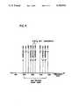
- 16 frequenciesare utilized in a frequency band from approximately 100 kiloHertz to 400 kiloHertz. These frequencies are chosen, such that the side bands of sets of four of the frequencies, do not overlap, and such that, at least pairs (and preferably sets of four) frequencies have no least common denominator (i.e. are prime to each other). Such frequencies are herein referred to as orthogonal.
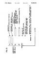
- messagesare sent in blocks of 21 bytes of eight bits each comprising a sync byte, an address byte, a protocol byte, a frequency selection byte, 15 data bytes, and two bytes of error correction code.
- a data blockis transmitted on a first frequency and simultaneously its complement is transmitted on a different frequency. That is, on the first frequency, presence of carrier is a one and lack of carrier is a zero, while on the second frequency, the presence of carrier is a zero and lack of carrier is a one or vice versa.
- the blockis retransmitted on a second pair of frequencies after remapping of the bits of the block into a different sequence, such that no two bits, which are adjacent in the first transmission are adjacent in the second transmission and the same bit is never present in the second block, 8.33 milliseconds after its presence in the first block, since this is the repetition rate of 120 hertz impulse noise.
- the transmission rateis 30 kilobits per second and each data block, consisting of 168 bits, takes 5.6 milliseconds for transmission. This provides an information rate of 15 bytes in 11.2 milliseconds, that is 10,714 bits per second, which is equivalent to a 14,667 bits per second asynchronous rate.
- the transceiver according to the inventionis, therefore, provided with a protocol program and a I/O program, which may operate on separate computers or through time sharing on a single computer.
- the I/O programtransmits a frequency code to a digital counter which changes its counting modulus so as to produce the correct frequency for transmission, which is then gated and wave shaped under control of data supplied by the physical I/O program.
- the I/O programDuring reception, a pair of digital state machines are provided, each for receiving one of the two simultaneous frequencies being received, the I/O program provides a frequency code to a frequency controlled filter, which passes the appropriate frequency to the digital state machine, which utilizing the clock signal and a frequency code, sets itself to receive the transmitted frequency.
- the frequency controlled filtermay comprise an operational amplifier, having a frequency controlled feedback loop. If 16 frequencies are employed, one of 16 RC constants are chosen by the frequency code through selection of resistance or capacitance in the feedback loop.
- detection of an uncorrectable error after the spread spectrum-time diversity transmission of a data blockwill cause the receiver to transmit an error message to the sending transceiver, which will retransmit the data block.
- Meansare provided for initializing the system so that all transceivers are operating on the same two sets of frequency pairs.
- Frequenciesare chosen using a hill-climbing technique so that communications converge to areas of the spectrum having the most favorable signal to noise ratios.
- Another object of the inventionis to provide such communications utilizing spread spectrum and time diversity techniques.
- a further object of the inventionis to provide for such communications in industrial environments over power lines, dedicated pairs, automated guided vehicle floor loops, and similar noisy transmission channels.
- Another object of the inventionis to increase the data rates in such communications.
- a still further object of the inventionis to reduce error rates in such communications.
- the inventionaccordingly comprises the features of construction, several elements, the arrangements of parts, and the choice of functions and signals, which will be exemplified in the construction of the systems hereinafter set forth.
- the scope of the inventionis indicated in the claims.
- FIG. 1is a schematic block circuit diagram of a system according to the invention
- FIG. 2is a diagram of a message block according to the invention.
- FIG. 3is a diagram of frequency versus time illustrating the time diversity and spread spectrum techniques employed in the invention
- FIG. 4is a diagram showing how a set of four frequencies may be chosen for orthogonality and no band overlap
- FIG. 5is a schematic block circuit diagram of an alternative carrier synthesizer and
- FIG. 6is a diagram of a coupling antenna to an AC transmission line.
- FIG. 1An overall block diagram of a transceiver according to the invention is shown in FIG. 1. It consists of the following blocks:
- a protocol microprocessor 10implements network access, addressing, error control and recovery.
- a physical I/O microprocessor 12collects bit-level error statistics, determines operating frequencies, and controls transmit and receive hardware. Although shown as two separate functional blocks, these two microprocessors might be implemented in same hardware, i.e. the protocol and physical I/O programs could be time shared on the same computer.
- An analog transmit section 14generates carrier, gated by a coded bit stream coupling network 16, couples signal to transmission wire, and provides impulse protection.
- An analog receive section 16comprises a broad band front-end 18, clipper 20, narrow-band filters, 22, 24 tuned to one of 16 frequencies under control of the physical I/O micro 12 by switching in different resistors or superhet with transmit clock, followed by comparators, 26, 28.
- Digital state machines, 30, 32each have its detected frequency controlled by the physical I/O micro, so it correlates on the proper frequency.
- Micro 10supports a host interface, in the same way as in the above-identified patent. It implements the polling protocol disclosed therein or, as an alternative, may implement a cyclic time division protocol to provide multipoint communication and initiation of the communications link from any subscriber.
- Micro 10transmits information in each message showing the frequencies to be used in the next message block.
- a message block formatis shown in FIG. 2.
- Micro 12uses frequency and time diversity to spread the signal. This is illustrated in FIG. 3, and meets the time and data rate constraints one practical application. Two pairs of frequencies each of which forms an FSK (Frequency Shift Keying) pair, are transmitted one after the other.
- FSKFrequency Shift Keying
- each half of each FSK pairis treated as a separate signal, with error coding built in so that the entire message can be recovered in the absence of any of the other three frequencies.
- bit significanceis inverted between the two members of the FSK pair, a particular noise situation which tends to destroy carrier acquisition (low frequency noise saturating the clipper) or noise which tends to cause false acquisition (in-band noise) will affect only one of the two bit streams. Bit order is scrambled to increase the effective gain of the error coding in the presence of burst errors.
- the message structureis chosen so that if an error occurs at any point in one of the two time diverse-pairs, its recurrence 1/120th of a second later will cause an error in a different set of bits, so the message can still be reconstructed. Adjacent bits in the first sequence are never adjacent in the second sequence.
- the systemretries.
- the retriesare asynchronous to 120 hz and a technique common in image-enhancement systems is used.
- the old block with uncorrectable errorsis saved. If the next also has uncorrectable errors, it is overlaid with the last block, and, if the number of bits by which they differ is small, systematic combinations of the differing bits are tested through the coding algorithm, in order to build a complete message without having to get it all in the same retry.
- the four frequencies usedare chosen from a set of 16 possible frequencies, so they are mutually orthogonal to one another to minimize the effects of multipath at any point affecting more than one. Since each individual frequency is on-off keyed, it will generate side bands offset by the bit rate from the carrier. The different frequencies are chosen so as not to interfere with the sidebands as well as the fundamental.
- a possible spectrum utilization for the bandwidth of 160 to 300 kHz, with a 30 KPBS data rateis illustrated in FIG. 4.
- a slave transceiverTo acquire the network when powered up, or after losing frequency sync, a slave transceiver listens to the 16 frequencies two at a time, stepping through the 8 available frequency sets at a rate of one change every 11.2 msec. (or two frames). This ultimately results in hearing a valid message, which will contain the correct frequency code to which the transceiver will then lock.
- Choice of the particular frequencies to be used at any timeis controlled by a master unit.
- access-control and frequency controlare treated independently; indeed a hot backup system can be included so that if the unit designated as the frequency control master goes off line, another designated unit detects this fact and takes over.
- the frequency control mastercollects data internally on the corrected error rates for messages received on the different channels, and, as grosser measure, on the retry rates.
- Special message formatsare to be provided (see FIG. 3) so that the master can periodically interrogate other units and determine their received error rates for each frequency. These error rates are filtered (smoothed) to emphasize recent performance, the time constant being chosen based upon the expected time-rate-of-change of the noise Power Spectral Density function.
- each vehicleFor guided vehicle applications, separate frequency sets may be maintained for each vehicle. Since each 168 bit packet is transmitted doubly-redundantly in 1/2 msec, about 89 adjustments per second will occur, which is more than adequate to move frequencies away from a dead spot in the wire as a vehicle traverses it. This results in each vehicle in the system working with its own set of frequencies.
- the memory cost--16 bits per vehicle, stored at the master,is modest.
- each of the sixteen frequenciesis represented by four bits of data output by the physical I/O processor. These bits are used to load a counter 34, which is clocked by clock 35 at some higher rate, in a manner analogous to the use of dip switches (in place of the four bits) to control UART clock rate in the above-identified patent.
- the resulting logic level square wave, at the desired carrier frequency,is fed to low pass filter 16 to round the edges.
- the bandwidth employedis less than a factor of two, the harmonic content of the imperfect sine wave resulting does not produce significant clutter. If this is a problem, more expensive and complicated frequency synthesis may be employed, either in analog or by digital synthesis of a string of 4-bit values, through a PROM 36, which are then analog-to-digital converted in counter 38 and smoothed as in FIG. 5.
- a ferrite antenna 40may be curved rather than straight, largely enveloping the communicating conductor 42, as shown in FIG. 6. This approach reduces the cost of required protection circuitry as compared to a direct wired connection.
- the analog filter section 16must be controllable with respect to its center frequency. This is achieved by using the four bit frequency command to switch different RC values (time delays) into the feedback of the amplifier. Two such analog sections are provided, operating independently in parallel for the two frequencies active at any point in time.
- Two state machine correlation detectors 30, 32follow the analog filters 22, 24 and comparators 26, 28; they are similar in operation to, those in the above-identified patent, but have target frequency as an additional input from counters 27 and 29, respectively. They, therefore, track the two frequencies currently commanded by the micro 12, and output independent bit streams to it. (It may be efficient to embody these two state machines in a single chip or chip set; this does not affect their logical independence).
Landscapes
- Engineering & Computer Science (AREA)
- Computer Networks & Wireless Communication (AREA)
- Signal Processing (AREA)
- Power Engineering (AREA)
- Physics & Mathematics (AREA)
- Electromagnetism (AREA)
- Aviation & Aerospace Engineering (AREA)
- Radar, Positioning & Navigation (AREA)
- Remote Sensing (AREA)
- General Physics & Mathematics (AREA)
- Automation & Control Theory (AREA)
- Radio Transmission System (AREA)
- Mobile Radio Communication Systems (AREA)
- Detection And Prevention Of Errors In Transmission (AREA)
Abstract
Description
Claims (11)
Priority Applications (4)
| Application Number | Priority Date | Filing Date | Title |
|---|---|---|---|
| US07/333,336US5168510A (en) | 1984-03-06 | 1989-04-05 | Spread spectrum-time diversity communications systems and transceivers for multidrop area networks |
| AU54316/90AAU5431690A (en) | 1989-04-05 | 1990-04-04 | Spread spectrum-time diversity communications systems and transceivers for multidrop local area networks |
| PCT/US1990/001823WO1990012463A1 (en) | 1989-04-05 | 1990-04-04 | Spread spectrum-time diversity communications systems and transceivers for multidrop local area networks |
| US07/920,110US5448593A (en) | 1984-03-06 | 1992-07-24 | Frequency hopping time-diversity communications systems and transceivers for local area networks |
Applications Claiming Priority (5)
| Application Number | Priority Date | Filing Date | Title |
|---|---|---|---|
| US06/586,863US4597082A (en) | 1984-03-06 | 1984-03-06 | Transceiver for multi-drop local area networks |
| US84692486A | 1986-04-01 | 1986-04-01 | |
| US11524587A | 1987-10-30 | 1987-10-30 | |
| US07/309,272US5257290A (en) | 1984-03-06 | 1989-02-10 | Transmission line termination of guide-communications wire for guided vehicles |
| US07/333,336US5168510A (en) | 1984-03-06 | 1989-04-05 | Spread spectrum-time diversity communications systems and transceivers for multidrop area networks |
Related Parent Applications (1)
| Application Number | Title | Priority Date | Filing Date |
|---|---|---|---|
| US07/309,272Continuation-In-PartUS5257290A (en) | 1984-03-06 | 1989-02-10 | Transmission line termination of guide-communications wire for guided vehicles |
Related Child Applications (1)
| Application Number | Title | Priority Date | Filing Date |
|---|---|---|---|
| US07/920,110Continuation-In-PartUS5448593A (en) | 1984-03-06 | 1992-07-24 | Frequency hopping time-diversity communications systems and transceivers for local area networks |
Publications (1)
| Publication Number | Publication Date |
|---|---|
| US5168510Atrue US5168510A (en) | 1992-12-01 |
Family
ID=23302357
Family Applications (1)
| Application Number | Title | Priority Date | Filing Date |
|---|---|---|---|
| US07/333,336Expired - Fee RelatedUS5168510A (en) | 1984-03-06 | 1989-04-05 | Spread spectrum-time diversity communications systems and transceivers for multidrop area networks |
Country Status (3)
| Country | Link |
|---|---|
| US (1) | US5168510A (en) |
| AU (1) | AU5431690A (en) |
| WO (1) | WO1990012463A1 (en) |
Cited By (35)
| Publication number | Priority date | Publication date | Assignee | Title |
|---|---|---|---|---|
| US5404374A (en)* | 1993-07-12 | 1995-04-04 | Apple Computer, Inc. | Method and apparatus for transmitting and receiving encoded data using multiple frequency coding |
| US5500650A (en)* | 1992-12-15 | 1996-03-19 | Micron Technology, Inc. | Data communication method using identification protocol |
| US5553081A (en)* | 1994-04-08 | 1996-09-03 | Echelon Corporation | Apparatus and method for detecting a signal in a communications system |
| US5583850A (en)* | 1992-12-15 | 1996-12-10 | Micron Technology, Inc. | Data communication system using identification protocol |
| US5818821A (en) | 1994-12-30 | 1998-10-06 | Intelogis, Inc. | Universal lan power line carrier repeater system and method |
| US5933415A (en)* | 1995-07-13 | 1999-08-03 | Sgs-Thomson Microelectronics S.A. | Circuit for transmitting binary data on the electric network using several transmission channels |
| US5940436A (en)* | 1995-07-13 | 1999-08-17 | Sgs-Thomson Microelectronics S.A. | Circuit for allocating a transmission channel on the electric network |
| US5970127A (en) | 1997-10-16 | 1999-10-19 | Phonex Corporation | Caller identification system for wireless phone jacks and wireless modem jacks |
| US6055435A (en) | 1997-10-16 | 2000-04-25 | Phonex Corporation | Wireless telephone connection surge suppressor |
| US6107912A (en) | 1997-12-08 | 2000-08-22 | Phonex Corporation | Wireless modem jack |
| US6243571B1 (en) | 1998-09-21 | 2001-06-05 | Phonex Corporation | Method and system for distribution of wireless signals for increased wireless coverage using power lines |
| US6246868B1 (en) | 1998-08-14 | 2001-06-12 | Phonex Corporation | Conversion and distribution of incoming wireless telephone signals using the power line |
| US20010014090A1 (en)* | 1998-02-19 | 2001-08-16 | Wood Clifton W. | Method of addressing messages and communications system |
| US6298052B1 (en)* | 1997-03-03 | 2001-10-02 | Alcatel | Communication method used in a shared resource transmission system |
| US6362737B1 (en) | 1998-06-02 | 2002-03-26 | Rf Code, Inc. | Object Identification system with adaptive transceivers and methods of operation |
| US20020190845A1 (en)* | 1999-08-09 | 2002-12-19 | Micron Technology, Inc. | RFID material tracking method and apparatus |
| US20030030568A1 (en)* | 2001-06-14 | 2003-02-13 | Roc Lastinger | Wireless identification systems and protocols |
| US20050040961A1 (en)* | 1995-04-11 | 2005-02-24 | Tuttle John R. | RF identification system with restricted range |
| US20080117025A1 (en)* | 1992-12-15 | 2008-05-22 | Tuttle John R | RFID System and Method for Wirelessly Interfacing With an Interrogator |
| US20080180221A1 (en)* | 2007-01-30 | 2008-07-31 | Micron Technology, Inc. | Systems and methods for RFID tag arbitration |
| US20080212303A1 (en)* | 2007-03-02 | 2008-09-04 | Warren Farnworth | Device for reducing or preventing exchange of information |
| US7424031B2 (en) | 1998-07-28 | 2008-09-09 | Serconet, Ltd. | Local area network of serial intelligent cells |
| US20080297324A1 (en)* | 2007-05-30 | 2008-12-04 | Micron Technology, Inc. | Methods and systems of receiving data payload of rfid tags |
| USRE40686E1 (en) | 1998-02-19 | 2009-03-31 | Keystone Technology Solutions, Llc | Method of addressing messages and communications system |
| US7583192B2 (en) | 1992-08-12 | 2009-09-01 | Keystone Technology Solutions, Llc | Radio frequency identification device and method |
| US7656904B2 (en) | 2003-03-13 | 2010-02-02 | Mosaid Technologies Incorporated | Telephone system having multiple distinct sources and accessories therefor |
| US20100188265A1 (en)* | 2009-01-23 | 2010-07-29 | Hill Lawrence W | Network Providing Vehicles with Improved Traffic Status Information |
| USRE41531E1 (en) | 1998-02-19 | 2010-08-17 | Round Rock Research, Llc | Communications systems for radio frequency identification (RFID) |
| US7839285B2 (en) | 1997-08-20 | 2010-11-23 | Round Rock Resarch, LLC | Electronic communication devices, methods of forming electrical communication devices, and communications methods |
| US7876767B2 (en) | 2000-04-19 | 2011-01-25 | Mosaid Technologies Incorporated | Network combining wired and non-wired segments |
| USRE42344E1 (en) | 1998-02-19 | 2011-05-10 | Round Rock Research, Llc | Method and apparatus to manage RFID tags |
| USRE43382E1 (en) | 1998-02-19 | 2012-05-15 | Round Rock Research, Llc | Method of addressing messages and communications systems |
| DE102011010792A1 (en)* | 2011-02-09 | 2012-08-09 | Conductix-Wampfler Ag | Device for energy transmission and enabling inductive communication of moving objects, has communication unit connected with inductance unit and provided with modem operated according to orthogonal frequency-division multiplexing |
| DE102011010793A1 (en)* | 2011-02-09 | 2012-08-09 | Conductix-Wampfler Ag | Use of modem in communication device for inductive communication with track-guided or rail-guided movable object via untwisted symmetrical two wire line, using communication inductor connected with communication device |
| US9172435B2 (en) | 2011-02-09 | 2015-10-27 | Conductix-Wampfler Gmbh | Apparatus for power transmission and for inductive communication |
Families Citing this family (3)
| Publication number | Priority date | Publication date | Assignee | Title |
|---|---|---|---|---|
| US5448593A (en)* | 1984-03-06 | 1995-09-05 | Cyplex Corporation | Frequency hopping time-diversity communications systems and transceivers for local area networks |
| JPH08195703A (en)* | 1995-01-17 | 1996-07-30 | Toshiba Corp | Wireless communication device |
| CN104618076B (en)* | 2013-11-04 | 2018-05-18 | 华为技术有限公司 | Data repeating method and communication equipment |
Citations (15)
| Publication number | Priority date | Publication date | Assignee | Title |
|---|---|---|---|---|
| US3160711A (en)* | 1960-06-04 | 1964-12-08 | Bell Telephone Labor Inc | Nonsynchronous time-frequency multiplex transmission system |
| US3199077A (en)* | 1961-08-21 | 1965-08-03 | Collins Radio Co | Code and complement testing device |
| US3214691A (en)* | 1960-05-13 | 1965-10-26 | Nat Company Inc | Frequency diversity communications system |
| US3631232A (en)* | 1969-10-17 | 1971-12-28 | Xerox Corp | Apparatus for simulating the electrical characteristics of a network |
| US3751596A (en)* | 1971-11-29 | 1973-08-07 | Ibm | Data transmission system using complementary coding sequences |
| US3783385A (en)* | 1972-11-28 | 1974-01-01 | Itt | Digital diversity combiner |
| US3963988A (en)* | 1973-12-06 | 1976-06-15 | Siemens Aktiengesellschaft | Circuit arrangement for selecting a diversity channel |
| US4063174A (en)* | 1975-07-02 | 1977-12-13 | Siemens Aktiengesellschaft | Circuit arrangement for diversity data transmission |
| US4099121A (en)* | 1976-06-11 | 1978-07-04 | Communications Satellite Corporation | Spatial diversity satellite communications system with error control |
| US4186347A (en)* | 1978-10-31 | 1980-01-29 | Nasa | Radio frequency arraying method for receivers |
| US4320526A (en)* | 1980-03-03 | 1982-03-16 | Bell Telephone Laboratories, Incorporated | Adaptive phase-jitter tracker |
| US4460992A (en)* | 1982-11-04 | 1984-07-17 | The United States Of America As Represented By The Secretary Of The Army | Orthogonal CDMA system utilizing direct sequence pseudo noise codes |
| US4494238A (en)* | 1982-06-30 | 1985-01-15 | Motorola, Inc. | Multiple channel data link system |
| US4628517A (en)* | 1981-05-27 | 1986-12-09 | Siemens Aktiengesellschaft | Digital radio system |
| US4641318A (en)* | 1985-04-25 | 1987-02-03 | Bell Communications Research, Inc. | Method for improving the reliability of data transmission over Rayleigh fading channels |
- 1989
- 1989-04-05USUS07/333,336patent/US5168510A/ennot_activeExpired - Fee Related
- 1990
- 1990-04-04AUAU54316/90Apatent/AU5431690A/ennot_activeAbandoned
- 1990-04-04WOPCT/US1990/001823patent/WO1990012463A1/enunknown
Patent Citations (15)
| Publication number | Priority date | Publication date | Assignee | Title |
|---|---|---|---|---|
| US3214691A (en)* | 1960-05-13 | 1965-10-26 | Nat Company Inc | Frequency diversity communications system |
| US3160711A (en)* | 1960-06-04 | 1964-12-08 | Bell Telephone Labor Inc | Nonsynchronous time-frequency multiplex transmission system |
| US3199077A (en)* | 1961-08-21 | 1965-08-03 | Collins Radio Co | Code and complement testing device |
| US3631232A (en)* | 1969-10-17 | 1971-12-28 | Xerox Corp | Apparatus for simulating the electrical characteristics of a network |
| US3751596A (en)* | 1971-11-29 | 1973-08-07 | Ibm | Data transmission system using complementary coding sequences |
| US3783385A (en)* | 1972-11-28 | 1974-01-01 | Itt | Digital diversity combiner |
| US3963988A (en)* | 1973-12-06 | 1976-06-15 | Siemens Aktiengesellschaft | Circuit arrangement for selecting a diversity channel |
| US4063174A (en)* | 1975-07-02 | 1977-12-13 | Siemens Aktiengesellschaft | Circuit arrangement for diversity data transmission |
| US4099121A (en)* | 1976-06-11 | 1978-07-04 | Communications Satellite Corporation | Spatial diversity satellite communications system with error control |
| US4186347A (en)* | 1978-10-31 | 1980-01-29 | Nasa | Radio frequency arraying method for receivers |
| US4320526A (en)* | 1980-03-03 | 1982-03-16 | Bell Telephone Laboratories, Incorporated | Adaptive phase-jitter tracker |
| US4628517A (en)* | 1981-05-27 | 1986-12-09 | Siemens Aktiengesellschaft | Digital radio system |
| US4494238A (en)* | 1982-06-30 | 1985-01-15 | Motorola, Inc. | Multiple channel data link system |
| US4460992A (en)* | 1982-11-04 | 1984-07-17 | The United States Of America As Represented By The Secretary Of The Army | Orthogonal CDMA system utilizing direct sequence pseudo noise codes |
| US4641318A (en)* | 1985-04-25 | 1987-02-03 | Bell Communications Research, Inc. | Method for improving the reliability of data transmission over Rayleigh fading channels |
Cited By (90)
| Publication number | Priority date | Publication date | Assignee | Title |
|---|---|---|---|---|
| US7746230B2 (en) | 1992-08-12 | 2010-06-29 | Round Rock Research, Llc | Radio frequency identification device and method |
| US7583192B2 (en) | 1992-08-12 | 2009-09-01 | Keystone Technology Solutions, Llc | Radio frequency identification device and method |
| US8018340B2 (en) | 1992-08-12 | 2011-09-13 | Round Rock Research, Llc | System and method to track articles at a point of origin and at a point of destination using RFID |
| US5627544A (en)* | 1992-12-15 | 1997-05-06 | Micron Technology, Inc. | Data communication method using identification protocol |
| US5500650A (en)* | 1992-12-15 | 1996-03-19 | Micron Technology, Inc. | Data communication method using identification protocol |
| US5583850A (en)* | 1992-12-15 | 1996-12-10 | Micron Technology, Inc. | Data communication system using identification protocol |
| US5841770A (en)* | 1992-12-15 | 1998-11-24 | Micron Technology, Inc. | Data communication system using indentification protocol |
| US20080117025A1 (en)* | 1992-12-15 | 2008-05-22 | Tuttle John R | RFID System and Method for Wirelessly Interfacing With an Interrogator |
| US5404374A (en)* | 1993-07-12 | 1995-04-04 | Apple Computer, Inc. | Method and apparatus for transmitting and receiving encoded data using multiple frequency coding |
| US5553081A (en)* | 1994-04-08 | 1996-09-03 | Echelon Corporation | Apparatus and method for detecting a signal in a communications system |
| US5818821A (en) | 1994-12-30 | 1998-10-06 | Intelogis, Inc. | Universal lan power line carrier repeater system and method |
| US20070290854A1 (en)* | 1995-04-11 | 2007-12-20 | Tuttle John R | RF Identification System with Restricted Range |
| US20050040961A1 (en)* | 1995-04-11 | 2005-02-24 | Tuttle John R. | RF identification system with restricted range |
| US20070290811A1 (en)* | 1995-04-11 | 2007-12-20 | Tuttle John R | RF Identification System with Restricted Range |
| US5940436A (en)* | 1995-07-13 | 1999-08-17 | Sgs-Thomson Microelectronics S.A. | Circuit for allocating a transmission channel on the electric network |
| US5933415A (en)* | 1995-07-13 | 1999-08-03 | Sgs-Thomson Microelectronics S.A. | Circuit for transmitting binary data on the electric network using several transmission channels |
| US6349111B1 (en) | 1995-07-13 | 2002-02-19 | Sgs-Thomson Microelectronics S.A. | Circuit for allocating a transmission channel on the electric network |
| US6298052B1 (en)* | 1997-03-03 | 2001-10-02 | Alcatel | Communication method used in a shared resource transmission system |
| US7839285B2 (en) | 1997-08-20 | 2010-11-23 | Round Rock Resarch, LLC | Electronic communication devices, methods of forming electrical communication devices, and communications methods |
| US7948382B2 (en) | 1997-08-20 | 2011-05-24 | Round Rock Research, Llc | Electronic communication devices, methods of forming electrical communication devices, and communications methods |
| US6055435A (en) | 1997-10-16 | 2000-04-25 | Phonex Corporation | Wireless telephone connection surge suppressor |
| US5970127A (en) | 1997-10-16 | 1999-10-19 | Phonex Corporation | Caller identification system for wireless phone jacks and wireless modem jacks |
| US6107912A (en) | 1997-12-08 | 2000-08-22 | Phonex Corporation | Wireless modem jack |
| US7672260B2 (en) | 1998-02-19 | 2010-03-02 | Keystone Technology Solutions, Llc | Method of addressing messages and communications system |
| USRE41530E1 (en) | 1998-02-19 | 2010-08-17 | Round Rock Research, Llc | Method and apparatus to select radio frequency identification devices in accordance with an arbitration scheme |
| US9014077B2 (en) | 1998-02-19 | 2015-04-21 | Round Rock Research, Llc | Methods and apparatus for conducting financial transactions |
| US8638709B2 (en) | 1998-02-19 | 2014-01-28 | Round Rock Research, Llc | Methods and apparatus for conducting financial transactions |
| US20060056325A1 (en)* | 1998-02-19 | 2006-03-16 | Wood Clifton W Jr | Method of addressing messages and communications system |
| US8634338B2 (en) | 1998-02-19 | 2014-01-21 | Round Rock Research, Llc | Methods and apparatus for conducting financial transactions |
| USRE44411E1 (en) | 1998-02-19 | 2013-08-06 | Round Rock Research, Llc | Method of addressing messages, method of establishing wireless communications and communications system |
| US7315522B2 (en) | 1998-02-19 | 2008-01-01 | Micron Technology, Inc. | Communication methods using slotted replies |
| US20080007412A1 (en)* | 1998-02-19 | 2008-01-10 | Wood Clifton W Jr | Method of Addressing Messages and Communications System |
| US20080042806A1 (en)* | 1998-02-19 | 2008-02-21 | Wood Clifton W Jr | Method of Addressing Messages and Communications System |
| US20050207364A1 (en)* | 1998-02-19 | 2005-09-22 | Wood Clifton W Jr | Method of addressing messages and communications system |
| US8488581B2 (en) | 1998-02-19 | 2013-07-16 | Round Rock Research, Llc | Methods and apparatus for conducting financial transactions |
| USRE43445E1 (en) | 1998-02-19 | 2012-06-05 | Round Rock Research, Llc | Method and apparatus to manage RFID tags |
| USRE43382E1 (en) | 1998-02-19 | 2012-05-15 | Round Rock Research, Llc | Method of addressing messages and communications systems |
| USRE43020E1 (en) | 1998-02-19 | 2011-12-13 | Round Rock Research, Llc | Method of addressing messages, method of establishing wireless communications, and communications system |
| USRE40686E1 (en) | 1998-02-19 | 2009-03-31 | Keystone Technology Solutions, Llc | Method of addressing messages and communications system |
| USRE42900E1 (en) | 1998-02-19 | 2011-11-08 | Round Rock Research, Llc | Method of addressing messages and communications systems |
| US20060209781A1 (en)* | 1998-02-19 | 2006-09-21 | Micron Technology, Inc. | Method of addressing messages and communications system |
| US7639638B2 (en) | 1998-02-19 | 2009-12-29 | Keystone Technology Solutions, Llc | Method and apparatus for an arbitration scheme for radio frequency identification devices |
| US8040829B2 (en) | 1998-02-19 | 2011-10-18 | Round Rock Research, Llc | Method of addressing messages and communications system |
| USRE42344E1 (en) | 1998-02-19 | 2011-05-10 | Round Rock Research, Llc | Method and apparatus to manage RFID tags |
| USRE41352E1 (en) | 1998-02-19 | 2010-05-25 | Keystone Technology Solutions, Llc | Method of addressing messages and communications |
| USRE42254E1 (en) | 1998-02-19 | 2011-03-29 | Round Rock Research, Llc | Method of addressing messages and communications system |
| US7760677B2 (en) | 1998-02-19 | 2010-07-20 | Keystone Technology Solutions, Llc | Method of addressing messages and communications system |
| US20010014090A1 (en)* | 1998-02-19 | 2001-08-16 | Wood Clifton W. | Method of addressing messages and communications system |
| USRE41471E1 (en) | 1998-02-19 | 2010-08-03 | Round Rock Research, Llc | Method of Addressing Messages and Communications System |
| USRE41531E1 (en) | 1998-02-19 | 2010-08-17 | Round Rock Research, Llc | Communications systems for radio frequency identification (RFID) |
| US7633378B2 (en) | 1998-06-02 | 2009-12-15 | Rf Code, Inc. | Object identification system with adaptive transceivers and methods of operation |
| US6362737B1 (en) | 1998-06-02 | 2002-03-26 | Rf Code, Inc. | Object Identification system with adaptive transceivers and methods of operation |
| US8867523B2 (en) | 1998-07-28 | 2014-10-21 | Conversant Intellectual Property Management Incorporated | Local area network of serial intelligent cells |
| US7978726B2 (en) | 1998-07-28 | 2011-07-12 | Mosaid Technologies Incorporated | Local area network of serial intelligent cells |
| US8885659B2 (en) | 1998-07-28 | 2014-11-11 | Conversant Intellectual Property Management Incorporated | Local area network of serial intelligent cells |
| US8908673B2 (en) | 1998-07-28 | 2014-12-09 | Conversant Intellectual Property Management Incorporated | Local area network of serial intelligent cells |
| US8885660B2 (en) | 1998-07-28 | 2014-11-11 | Conversant Intellectual Property Management Incorporated | Local area network of serial intelligent cells |
| US7424031B2 (en) | 1998-07-28 | 2008-09-09 | Serconet, Ltd. | Local area network of serial intelligent cells |
| US7852874B2 (en) | 1998-07-28 | 2010-12-14 | Mosaid Technologies Incorporated | Local area network of serial intelligent cells |
| US6246868B1 (en) | 1998-08-14 | 2001-06-12 | Phonex Corporation | Conversion and distribution of incoming wireless telephone signals using the power line |
| US6243571B1 (en) | 1998-09-21 | 2001-06-05 | Phonex Corporation | Method and system for distribution of wireless signals for increased wireless coverage using power lines |
| US8269605B2 (en) | 1999-08-09 | 2012-09-18 | Round Rock Research, Llc | RFID material tracking method and apparatus |
| US7808367B2 (en) | 1999-08-09 | 2010-10-05 | Round Rock Research, Llc | RFID material tracking method and apparatus |
| US20070296595A1 (en)* | 1999-08-09 | 2007-12-27 | Micron Technology, Inc. | RFID material tracking method and apparatus |
| US20070296596A1 (en)* | 1999-08-09 | 2007-12-27 | Micron Technology, Inc. | RFID material tracking method and apparatus |
| US8125316B2 (en) | 1999-08-09 | 2012-02-28 | Round Rock Research, Llc | RFID material tracking method and apparatus |
| US8378789B2 (en) | 1999-08-09 | 2013-02-19 | Round Rock Research, Llc | RFID material tracking method and apparatus |
| US20020190845A1 (en)* | 1999-08-09 | 2002-12-19 | Micron Technology, Inc. | RFID material tracking method and apparatus |
| US8848725B2 (en) | 2000-04-19 | 2014-09-30 | Conversant Intellectual Property Management Incorporated | Network combining wired and non-wired segments |
| US7876767B2 (en) | 2000-04-19 | 2011-01-25 | Mosaid Technologies Incorporated | Network combining wired and non-wired segments |
| US8982904B2 (en) | 2000-04-19 | 2015-03-17 | Conversant Intellectual Property Management Inc. | Network combining wired and non-wired segments |
| US8982903B2 (en) | 2000-04-19 | 2015-03-17 | Conversant Intellectual Property Management Inc. | Network combining wired and non-wired segments |
| US7933297B2 (en) | 2000-04-19 | 2011-04-26 | Mosaid Technologies Incorporated | Network combining wired and non-wired segments |
| US8873586B2 (en) | 2000-04-19 | 2014-10-28 | Conversant Intellectual Property Management Incorporated | Network combining wired and non-wired segments |
| US8873575B2 (en) | 2000-04-19 | 2014-10-28 | Conversant Intellectual Property Management Incorporated | Network combining wired and non-wired segments |
| US8867506B2 (en) | 2000-04-19 | 2014-10-21 | Conversant Intellectual Property Management Incorporated | Network combining wired and non-wired segments |
| US7030731B2 (en) | 2001-06-14 | 2006-04-18 | Rf Code, Inc. | Wireless identification systems and protocols |
| US20070008069A1 (en)* | 2001-06-14 | 2007-01-11 | Roc Lastinger | Wireless identification systems and protocols |
| US20030030568A1 (en)* | 2001-06-14 | 2003-02-13 | Roc Lastinger | Wireless identification systems and protocols |
| US7656904B2 (en) | 2003-03-13 | 2010-02-02 | Mosaid Technologies Incorporated | Telephone system having multiple distinct sources and accessories therefor |
| US8207856B2 (en) | 2007-01-30 | 2012-06-26 | Round Rock Research, Llc | Systems and methods for RFID tag arbitration where RFID tags generate multiple random numbers for different arbitration sessions |
| US7973644B2 (en) | 2007-01-30 | 2011-07-05 | Round Rock Research, Llc | Systems and methods for RFID tag arbitration where RFID tags generate multiple random numbers for different arbitration sessions |
| US20080180221A1 (en)* | 2007-01-30 | 2008-07-31 | Micron Technology, Inc. | Systems and methods for RFID tag arbitration |
| US20080212303A1 (en)* | 2007-03-02 | 2008-09-04 | Warren Farnworth | Device for reducing or preventing exchange of information |
| US8134452B2 (en) | 2007-05-30 | 2012-03-13 | Round Rock Research, Llc | Methods and systems of receiving data payload of RFID tags |
| US20080297324A1 (en)* | 2007-05-30 | 2008-12-04 | Micron Technology, Inc. | Methods and systems of receiving data payload of rfid tags |
| US20100188265A1 (en)* | 2009-01-23 | 2010-07-29 | Hill Lawrence W | Network Providing Vehicles with Improved Traffic Status Information |
| DE102011010793A1 (en)* | 2011-02-09 | 2012-08-09 | Conductix-Wampfler Ag | Use of modem in communication device for inductive communication with track-guided or rail-guided movable object via untwisted symmetrical two wire line, using communication inductor connected with communication device |
| DE102011010792A1 (en)* | 2011-02-09 | 2012-08-09 | Conductix-Wampfler Ag | Device for energy transmission and enabling inductive communication of moving objects, has communication unit connected with inductance unit and provided with modem operated according to orthogonal frequency-division multiplexing |
| US9172435B2 (en) | 2011-02-09 | 2015-10-27 | Conductix-Wampfler Gmbh | Apparatus for power transmission and for inductive communication |
Also Published As
| Publication number | Publication date |
|---|---|
| AU5431690A (en) | 1990-11-05 |
| WO1990012463A1 (en) | 1990-10-18 |
Similar Documents
| Publication | Publication Date | Title |
|---|---|---|
| US5168510A (en) | Spread spectrum-time diversity communications systems and transceivers for multidrop area networks | |
| US5448593A (en) | Frequency hopping time-diversity communications systems and transceivers for local area networks | |
| US7606287B2 (en) | Radio frequency communication network having adaptive communication parameters | |
| US5640415A (en) | Bit error performance of a frequency hopping, radio communication system | |
| KR910007712B1 (en) | Control Units and Stations for Wireless Communication Systems | |
| US4479215A (en) | Power-line carrier communications system with interference avoidance capability | |
| CA1280228C (en) | Digital radio transmission system | |
| US5084900A (en) | Spread spectrum system with random code retransmission | |
| US5432815A (en) | Data modulator-demodulator apparatus of a spread spectrum communication system | |
| US6128290A (en) | Personal data network | |
| US6466138B1 (en) | Meshed telemetry system using frequency hopping for intermittent transmission | |
| US5335247A (en) | Adaptive data rate packet communications system | |
| US20020021745A1 (en) | Multi-channel-bandwidth frequency-hopping system | |
| MXPA04006127A (en) | Frequency hopping spread spectrum communications system. | |
| US20120014413A1 (en) | Method for fast synchronization and frequency hop sequence detection in wireless sensor networks | |
| CA2219921A1 (en) | Spread spectrum communication network with adaptive frequency agility | |
| US7277411B2 (en) | Method and system for transmitting and receiving data in a TDMA frequency hopping system utilizing frequency diversity | |
| EP0857376A1 (en) | Data transmission method, transmitter, and receiver | |
| SE470594B (en) | Communication system | |
| WO1994010774A1 (en) | Radio frequency communication network having adaptive communication parameters | |
| EP0736982A2 (en) | Digital radio system including repeater equipment, end equipment, and receiver | |
| WO2000038402A1 (en) | Power line communication system for local area networks | |
| US5841807A (en) | Spread spectrum data communicator | |
| RU2189118C2 (en) | Data transmission method | |
| JPH0457144B2 (en) |
Legal Events
| Date | Code | Title | Description |
|---|---|---|---|
| AS | Assignment | Owner name:COMSOURCE SYSTEMS, NEW HAMPSHIRE Free format text:ASSIGNMENT OF ASSIGNORS INTEREST.;ASSIGNOR:HILL, LAWRENCE W.;REEL/FRAME:005092/0344 Effective date:19890425 | |
| FEPP | Fee payment procedure | Free format text:PAYOR NUMBER ASSIGNED (ORIGINAL EVENT CODE: ASPN); ENTITY STATUS OF PATENT OWNER: SMALL ENTITY | |
| AS | Assignment | Owner name:DBI CORPORATION, MASSACHUSETTS Free format text:ASSIGNMENT OF ASSIGNORS INTEREST;ASSIGNOR:CYPLEX CORPORATION;REEL/FRAME:007570/0914 Effective date:19950619 Owner name:PRIMARY BANK, NEW HAMPSHIRE Free format text:SECURITY AGREEMENT;ASSIGNOR:DBI CORPORATION;REEL/FRAME:007570/0918 Effective date:19950619 | |
| REMI | Maintenance fee reminder mailed | ||
| LAPS | Lapse for failure to pay maintenance fees | ||
| FP | Lapsed due to failure to pay maintenance fee | Effective date:19961204 | |
| AS | Assignment | Owner name:DBI CORPORATION, MASSACHUSETTS Free format text:RELEASE OF SECURITY INTEREST IN PATENTS;ASSIGNOR:PRIMARY BANK;REEL/FRAME:015005/0389 Effective date:20040205 | |
| STCH | Information on status: patent discontinuation | Free format text:PATENT EXPIRED DUE TO NONPAYMENT OF MAINTENANCE FEES UNDER 37 CFR 1.362 |