US5167662A - Temporary clamp and inserter for a posterior midline spinal clamp - Google Patents
Temporary clamp and inserter for a posterior midline spinal clampDownload PDFInfo
- Publication number
- US5167662A US5167662AUS07/825,344US82534492AUS5167662AUS 5167662 AUS5167662 AUS 5167662AUS 82534492 AUS82534492 AUS 82534492AUS 5167662 AUS5167662 AUS 5167662A
- Authority
- US
- United States
- Prior art keywords
- clamp
- temporary
- temporary clamp
- spinal
- halves
- Prior art date
- Legal status (The legal status is an assumption and is not a legal conclusion. Google has not performed a legal analysis and makes no representation as to the accuracy of the status listed.)
- Expired - Lifetime
Links
- 230000000712assemblyEffects0.000description5
- 238000000429assemblyMethods0.000description5
- 206010058907Spinal deformityDiseases0.000description2
- 238000000034methodMethods0.000description2
- 238000001356surgical procedureMethods0.000description2
- 230000004308accommodationEffects0.000description1
- 230000008602contractionEffects0.000description1
- 230000000994depressogenic effectEffects0.000description1
- 230000000717retained effectEffects0.000description1
- 210000003813thumbAnatomy0.000description1
Images


Classifications
- A—HUMAN NECESSITIES
- A61—MEDICAL OR VETERINARY SCIENCE; HYGIENE
- A61B—DIAGNOSIS; SURGERY; IDENTIFICATION
- A61B17/00—Surgical instruments, devices or methods
- A61B17/56—Surgical instruments or methods for treatment of bones or joints; Devices specially adapted therefor
- A61B17/58—Surgical instruments or methods for treatment of bones or joints; Devices specially adapted therefor for osteosynthesis, e.g. bone plates, screws or setting implements
- A61B17/68—Internal fixation devices, including fasteners and spinal fixators, even if a part thereof projects from the skin
- A61B17/70—Spinal positioners or stabilisers, e.g. stabilisers comprising fluid filler in an implant
- A61B17/7047—Clamps comprising opposed elements which grasp one vertebra between them
- A—HUMAN NECESSITIES
- A61—MEDICAL OR VETERINARY SCIENCE; HYGIENE
- A61B—DIAGNOSIS; SURGERY; IDENTIFICATION
- A61B17/00—Surgical instruments, devices or methods
- A61B17/28—Surgical forceps
- A61B17/2812—Surgical forceps with a single pivotal connection
- A—HUMAN NECESSITIES
- A61—MEDICAL OR VETERINARY SCIENCE; HYGIENE
- A61B—DIAGNOSIS; SURGERY; IDENTIFICATION
- A61B17/00—Surgical instruments, devices or methods
- A61B17/56—Surgical instruments or methods for treatment of bones or joints; Devices specially adapted therefor
- A61B17/58—Surgical instruments or methods for treatment of bones or joints; Devices specially adapted therefor for osteosynthesis, e.g. bone plates, screws or setting implements
- A61B17/68—Internal fixation devices, including fasteners and spinal fixators, even if a part thereof projects from the skin
- A61B17/70—Spinal positioners or stabilisers, e.g. stabilisers comprising fluid filler in an implant
- A61B17/7074—Tools specially adapted for spinal fixation operations other than for bone removal or filler handling
- A61B17/7076—Tools specially adapted for spinal fixation operations other than for bone removal or filler handling for driving, positioning or assembling spinal clamps or bone anchors specially adapted for spinal fixation
- A—HUMAN NECESSITIES
- A61—MEDICAL OR VETERINARY SCIENCE; HYGIENE
- A61B—DIAGNOSIS; SURGERY; IDENTIFICATION
- A61B17/00—Surgical instruments, devices or methods
- A61B17/56—Surgical instruments or methods for treatment of bones or joints; Devices specially adapted therefor
- A61B17/58—Surgical instruments or methods for treatment of bones or joints; Devices specially adapted therefor for osteosynthesis, e.g. bone plates, screws or setting implements
- A61B17/88—Osteosynthesis instruments; Methods or means for implanting or extracting internal or external fixation devices
- A61B17/8866—Osteosynthesis instruments; Methods or means for implanting or extracting internal or external fixation devices for gripping or pushing bones, e.g. approximators
- A—HUMAN NECESSITIES
- A61—MEDICAL OR VETERINARY SCIENCE; HYGIENE
- A61B—DIAGNOSIS; SURGERY; IDENTIFICATION
- A61B17/00—Surgical instruments, devices or methods
- A61B17/56—Surgical instruments or methods for treatment of bones or joints; Devices specially adapted therefor
- A61B17/58—Surgical instruments or methods for treatment of bones or joints; Devices specially adapted therefor for osteosynthesis, e.g. bone plates, screws or setting implements
- A61B17/68—Internal fixation devices, including fasteners and spinal fixators, even if a part thereof projects from the skin
- A61B17/70—Spinal positioners or stabilisers, e.g. stabilisers comprising fluid filler in an implant
- A61B17/7049—Connectors, not bearing on the vertebrae, for linking longitudinal elements together
Definitions
- This inventionrelates to a temporary clamp for a midline spinal clamp and to a temporary clamp inserter.
- a pair of rodsmay be connected to the spinal column of a patient by a series of spinal hooks. Distraction or contraction is applied to the rods between the hooks to straighten or support the spinal column of the patient.
- One form of spinal hookis referred to as midline clamp and includes a pair of hooks in sliding engagement with one another.
- a midline clampis illustrated in U.S. patent application Ser. No. 07/287,245 filed Dec. 12, 1988 in the name of Cozad el al., incorporated herein by reference.
- a clamp inserter(resembling a pair of pliers with a special jaw) directly engages each of the parts of the midline clamp to compress the midline clamp about the lamina.
- the midline clampsare formed from two slidable engaging hooks. Therefore, to maintain the clamps in position about the lamina until the rods are securely connected, the clamp inserter must remain connected to the midline clamp.
- each midline clamp and its connected insertermust remain attached to the spine until the spinal rods are connected and yet must be positioned out of the way of the surgeon.
- the inventionprovides a temporary clamp for connection to the midline clamp which holds the midline clamp in engagement about the lamina and is small enough to be substantially out of the way of the surgeon in use.
- the temporary clampis removably connected to the midline clamp by a pair of screws.
- the temporary clampis releasably connected to a clamp inserter such that after the midline clamp and temporary clamp is connected to the vertebra, the clamp inserted may be removed and used to connect subsequent temporary clamps. Therefore, since the clamp inserter may be removed from the surgical site without releasing the midline clamp, the surgeon may connect a plurality of the midline clamps with temporary clamps attached without significantly obstructing the surgical site.
- Another object of the inventionis to provide a temporary clamp for a midline spinal clamp which directly connects to the midline clamp.
- Another object of this inventionis to provide for a novel temporary clamp inserter.
- Yet another object of the inventionis to provide for a novel midline clamp adapted for connection to a temporary clamp.
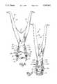
- FIG. 1is a fragmented elevation view of a spinal column having a pair of spinal rods connected to the vertebrae by a series of midline clamps and brackets.
- FIG. 2is a perspective view of a midline clamp of the invention.
- FIG. 3is an exploded perspective view of the midline clamp of FIG. 2.
- FIG. 4is a side elevational view of the connector for a midline clamp with portions cutaway for illustrative purposes.
- FIG. 5is an elevational view taken along line 5--5 of FIG. 4.
- FIGS. 6-8illustrate in series the procedure for connecting a midline clamp and connector to a vertebra and for releasing the inserter to leave the clamp and connector connected to the vertebra.
- FIG. 9is a front side elevational view of the inserter of the invention.
- FIG. 10is a rear side elevational view of the inserter handle.
- FIG. 11is a right side elevational view of the clamp handle.
- FIG. 1illustrates a spinal column 1 having a pair of longitudinal rods 3 connected to the spinal column by a plurality of midline clamps 10.
- Each midline clamp 10is attached to the rod by locking sleeve assemblies 2.
- the locking sleeve assembliesengage the rod sections in a known manner and are shiftably connected to the midline clamps by the accommodation of studs 4 within a slot opening on the locking sleeve assembly.
- a more detailed description of the structure and function of the locking sleeve assembliesmay be had by reference to the incorporated patent.
- the midline clamp 10 as illustrated in the figuresincludes an inferior clamp half 12 and a superior clamp half 14.
- the inferior clamp half 12includes a body 16, a posterior and anterior side and a shoe or a hook-like 18 configuration.
- superior clamp half 14includes a body 20 and a shoe or hook-like 22 configuration extending from the anterior side of the first and second clamp halves.
- the body 16 of inferior shoe 12is wider than the body 20 of superior shoe 14.
- the clamp halves 12, 14are slidably connected to one another through a cooperating L-shaped rib and groove formed in the clamp halves (not shown).
- the inferior clamp half 12has incorporated therewith a transverse outwardly extending stud 4 on an end of the body 16 as shown.
- the superior clamp half 14includes two studs 4 extending from the body 20. As mentioned previously, studs 4 of clamp halves 12, 14 are accommodated within a slot in the locking sleeve assemblies 2 to connect the clamp to the spinal rods. Each clamp half 12, 14 includes a threaded blind bore 13, 15, respectively, formed in the posterior side and the shoe end of the body extending from the front faces 24, 26 of the clamp halves.
- Temporary clamp 28includes generally L-shaped halves 30, 32.
- Half 30includes a body 34 having a front side edge 36, a rear side edge 38, a top edge 40, and a bottom edge 42.
- An arm 44extends from top edge 40 of body 34 and is generally perpendicular to the front edge 36.
- Arm 44includes a plurality of teeth 46 along its length. Arm 44 is smaller in cross section than body 34.
- Body 34further includes a squared opening 48 as illustrated.
- a bore 50extends from bottom edge 42 and is in communication with opening 48.
- a screw 52is carried within opening 48 and includes a threaded shaft which extends through bore 50.
- An opening 54is formed through body 34 between squared opening 48 and top edge 40.
- An abutment 56extends downwardly from bottom edge 42 of body 34.
- Temporary clamp half 32includes a body 58 having a front edge 60, a rear edge 62, a top edge 64, and a bottom edge 66.
- a squared opening 68is formed through body 58.
- a throughbore(not shown) extends from bottom edge 66 into squared opening 68.
- a screw 80is carried within squared opening 68 and includes a threaded shaft extending through the throughbore.
- An opening 72is formed through the body 58 and is oriented between squared opening 68 and top edge 64.
- An abutment 82extends downwardly from bottom edge 66 or body 58.
- a pair of arms 74extend along top edge 64 and are generally perpendicular with front edge 60 and rear edge 62.
- Arms 74are spaced apart to define a channel 76 therebetween extending along the top edge of body 58. Each arm 74 includes a protrusion 78.
- a ratchet arm 84having a handle portion 86 a ratchet tooth 88, and a center portion that extends towards the tooth end and is pivotally connected to body 58 by a connecting pin 90 traversing the ratchet arm and seated within aligned openings of protrusions 78 of arms 74.
- a pair of longitudinal slots 98are formed in the handle portion 86 of arm 84 and extend from a midpoint of the arm toward the handle end 92 terminating adjacent end 92. The slots define spring arms 94 for the handle portion.
- Each spring armincludes a fulcrum 96. Each fulcrum 96 connects an arm 74. Fulcrums 96 and spring arms 94 combine to bias handle end 92 away from arms 74.
- Clamp inserted 100includes a pair of cross linked handle parts 102, 104 pivotally connected to one another by a pin 106.
- Handle members 102, 104include jaw portions 108, 110.
- Leaf springs 112are connected to the handle part to bias the handle parts away from one another.
- Each jaw portion 108, 110includes a recessed section 114 forming a shoulder 116.
- a pin 118extends upwardly from the distal tip of the recessed portion.
- Pin 118includes an annular groove which is aligned with the upper surface of the shoulder 116.
- a clip 120is slidably connected to the jaw portion by a screw 122 and includes an open end for clamping about pin 118 at the annular grove.
- the clipincludes a thumb tab 124 for access by the user to slide the clip between an extended position wherein the clip extends over the recessed area and engaged pin 118 and a retracted position wherein the clip is clear of the recessed area.
- the inferior and superior clamp halvesare positioned in engagement with one another.
- Clamp halves 30, 32are positioned such that arm 44 of clamp half 30 is between arms 74 of clamp half 32 with the ratchet tooth 88 engaging teeth 46.
- One clamp half (30, 32)is connected to inferior clamp half by tuning screw 52 or 80 into the blind bore 13.
- the other clamp half (30, 32)is connected to the superior clamp half 14 in the same manner.
- abutments 56, 62contact the ends of the superior/inferior clamp halves.
- each haw of the inserterincludes a pin 118 extending transverse to the jaw.
- Pin 118 of each jaw 108, 110is inserted through opening 54 and 72 of temporary clamp halves 30, 32.
- the temporary clamp halvesseat against the recessed portions of the jaws.
- clips 120are slid into engagement with pins 118 with the temporary clamp halves retained therebetween (See FIGS. 6 and 7).
- the surgeonnext positions the midline clamp 10 about the lamina and squeezes the handles 86 of the inserter together causing the jaws to pivot toward each other and the spinal clamp and temporary clamp halves to compress together.
- the surgeoncontinues to position the midline clamp in clamping engagement with the vertebra. (See FIG. 7).
- Clips 120are shifted away from pins 118 and the inserter instrument pins are slid from openings 54 and 72 and the inserter instrument is removed.
- the ratchet engagement between ratchet tooth 88 and teeth 46 of the temporary clamp halvesholds the temporary clamp halves and the midline clamp in clamping engagement with the lamina. (See FIG. 8).
- the temporary clampmay be removed by turning screw 52 and 80 to rotate the screws out of bores 13 and 15.
Landscapes
- Health & Medical Sciences (AREA)
- Orthopedic Medicine & Surgery (AREA)
- Surgery (AREA)
- Life Sciences & Earth Sciences (AREA)
- Neurology (AREA)
- Medical Informatics (AREA)
- Biomedical Technology (AREA)
- Heart & Thoracic Surgery (AREA)
- Engineering & Computer Science (AREA)
- Molecular Biology (AREA)
- Animal Behavior & Ethology (AREA)
- General Health & Medical Sciences (AREA)
- Public Health (AREA)
- Veterinary Medicine (AREA)
- Nuclear Medicine, Radiotherapy & Molecular Imaging (AREA)
- Ophthalmology & Optometry (AREA)
- Surgical Instruments (AREA)
Abstract
Description
This invention relates to a temporary clamp for a midline spinal clamp and to a temporary clamp inserter.
To correct a spinal deformity, a pair of rods may be connected to the spinal column of a patient by a series of spinal hooks. Distraction or contraction is applied to the rods between the hooks to straighten or support the spinal column of the patient. One form of spinal hook is referred to as midline clamp and includes a pair of hooks in sliding engagement with one another. A midline clamp is illustrated in U.S. patent application Ser. No. 07/287,245 filed Dec. 12, 1988 in the name of Cozad el al., incorporated herein by reference.
During the surgical procedure it is not uncommon for the surgeon to loosely position a plurality of midline clamps along the spine of the patient prior to actually connecting the rods to the clamps. To connect the midline clamp to the lamina on the posterior side of the spine, a clamp inserter (resembling a pair of pliers with a special jaw) directly engages each of the parts of the midline clamp to compress the midline clamp about the lamina. As mentioned, the midline clamps are formed from two slidable engaging hooks. Therefore, to maintain the clamps in position about the lamina until the rods are securely connected, the clamp inserter must remain connected to the midline clamp. It would not be uncommon for a corrective spinal procedure to require a plurality of midline clamps each being connected and held in place by the clamp inserters in the manner described above. Therefore, using the current midline clamps and clamp inserter, each midline clamp and its connected inserter must remain attached to the spine until the spinal rods are connected and yet must be positioned out of the way of the surgeon. Typically, this would means that the clamp inserter must be held by a surgical assistant or laid down on the patient adjacent the surgical site. For example, if five midline clamps were to be connected, then there would be five clamp inserters along the surgical site.
The invention provides a temporary clamp for connection to the midline clamp which holds the midline clamp in engagement about the lamina and is small enough to be substantially out of the way of the surgeon in use. The temporary clamp is removably connected to the midline clamp by a pair of screws. The temporary clamp is releasably connected to a clamp inserter such that after the midline clamp and temporary clamp is connected to the vertebra, the clamp inserted may be removed and used to connect subsequent temporary clamps. Therefore, since the clamp inserter may be removed from the surgical site without releasing the midline clamp, the surgeon may connect a plurality of the midline clamps with temporary clamps attached without significantly obstructing the surgical site.
Accordingly, it is an object of this invention to provide for a novel temporary clamp for a midline spinal clamp.
Another object of the invention is to provide a temporary clamp for a midline spinal clamp which directly connects to the midline clamp.
Another object of this invention is to provide for a novel temporary clamp inserter.
Yet another object of the invention is to provide for a novel midline clamp adapted for connection to a temporary clamp.
Still other objects of the invention will become apparent upon a reading of the following description taken with the following drawings.
FIG. 1 is a fragmented elevation view of a spinal column having a pair of spinal rods connected to the vertebrae by a series of midline clamps and brackets.
FIG. 2 is a perspective view of a midline clamp of the invention.
FIG. 3 is an exploded perspective view of the midline clamp of FIG. 2.
FIG. 4 is a side elevational view of the connector for a midline clamp with portions cutaway for illustrative purposes.
FIG. 5 is an elevational view taken along line 5--5 of FIG. 4.
FIGS. 6-8 illustrate in series the procedure for connecting a midline clamp and connector to a vertebra and for releasing the inserter to leave the clamp and connector connected to the vertebra.
FIG. 9 is a front side elevational view of the inserter of the invention.
FIG. 10 is a rear side elevational view of the inserter handle.
FIG. 11 is a right side elevational view of the clamp handle.
The preferred embodiments herein disclosed are not intended to be exhaustive or to limit the invention to the precise forms disclosed. Rather, they are chosen and described to enable others skilled in the art to utilize its teachings.
FIG. 1 illustrates a spinal column 1 having a pair oflongitudinal rods 3 connected to the spinal column by a plurality ofmidline clamps 10. Eachmidline clamp 10 is attached to the rod bylocking sleeve assemblies 2. The locking sleeve assemblies engage the rod sections in a known manner and are shiftably connected to the midline clamps by the accommodation ofstuds 4 within a slot opening on the locking sleeve assembly. A more detailed description of the structure and function of the locking sleeve assemblies may be had by reference to the incorporated patent.
Themidline clamp 10 as illustrated in the figures includes aninferior clamp half 12 and asuperior clamp half 14. Theinferior clamp half 12 includes abody 16, a posterior and anterior side and a shoe or a hook-like 18 configuration. Similarly,superior clamp half 14 includes abody 20 and a shoe or hook-like 22 configuration extending from the anterior side of the first and second clamp halves. Thebody 16 ofinferior shoe 12 is wider than thebody 20 ofsuperior shoe 14. Theclamp halves inferior clamp half 12 has incorporated therewith a transverse outwardly extendingstud 4 on an end of thebody 16 as shown. Thesuperior clamp half 14 includes twostuds 4 extending from thebody 20. As mentioned previously,studs 4 ofclamp halves locking sleeve assemblies 2 to connect the clamp to the spinal rods. Eachclamp half blind bore front faces
Clamp inserted 100 includes a pair of cross linked handleparts pin 106. Handlemembers jaw portions 108, 110. Leaf springs 112 are connected to the handle part to bias the handle parts away from one another. Eachjaw portion 108, 110 includes a recessedsection 114 forming a shoulder 116. Apin 118 extends upwardly from the distal tip of the recessed portion.Pin 118 includes an annular groove which is aligned with the upper surface of the shoulder 116. Aclip 120 is slidably connected to the jaw portion by ascrew 122 and includes an open end for clamping aboutpin 118 at the annular grove. The clip includes athumb tab 124 for access by the user to slide the clip between an extended position wherein the clip extends over the recessed area and engagedpin 118 and a retracted position wherein the clip is clear of the recessed area.
In use, the inferior and superior clamp halves are positioned in engagement with one another. Clamp halves 30, 32 are positioned such thatarm 44 ofclamp half 30 is betweenarms 74 ofclamp half 32 with the ratchet tooth 88 engagingteeth 46. One clamp half (30, 32) is connected to inferior clamp half by tuningscrew blind bore 13. Similarly, the other clamp half (30, 32) is connected to thesuperior clamp half 14 in the same manner. As illustrated in the figures,abutments ratchet arm 84 to ratchet overteeth 46. However, handle 86 must be depressed to pivot thearm 84 for disengaging the ratchet tooth 88 fromteeth 46 to permit the midline clamp parts from shifting away from one another.
To connect themidline clamp 10, withtemporary clamp 28 attached thereto, to the lamina of a vertebrae,clamp inserter 100 is connected to the temporary clamp in the following manner. As illustrated and described previously, each haw of the inserter includes apin 118 extending transverse to the jaw.Pin 118 of eachjaw 108, 110 is inserted throughopening temporary clamp 28 to theclamp inserter 100,clips 120 are slid into engagement withpins 118 with the temporary clamp halves retained therebetween (See FIGS. 6 and 7).
The surgeon next positions themidline clamp 10 about the lamina and squeezes thehandles 86 of the inserter together causing the jaws to pivot toward each other and the spinal clamp and temporary clamp halves to compress together. The surgeon continues to position the midline clamp in clamping engagement with the vertebra. (See FIG. 7).
After thelocking sleeve assemblies 2 are connected to themidline clamp 10, or the clamp is secured to a spinal system by another means, the temporary clamp may be removed by turningscrew bores
It should be understood that during a surgical procedure to correct a spinal deformity, a number of the midline clamps may be required. Therefore, a like number of temporary clamps are required, but only oneclamp inserter instrument 100 is required to sequentially position the clamps.
It should also be understood that the invention is not to be limited to the details above, but may be modified within the scope of the appended claims.
Claims (5)
1. A temporary clamp for connection to a midline spinal clamp to temporarily maintain the spinal clamp in clamping engagement with a vertebra, the spinal clamp including first and second halves each having a posterior side, a threaded blind bore being formed in each posterior side of the first and second spinal clamp halves, the temporary clamp comprising a first temporary clamp half having a body and an arm extending therefrom, a screw being carried by the first temporarily clamp half body for turning within the blind bore of the first spinal clamp half to connect the first temporary clamp half to the first spinal clamp half, a second temporary clamp half having a body and a pair of parallel arms extending therefrom, a screw being carried by the second temporary clamp half for turning within the blind bore of the second spinal clamp half to connect the second temporary clamp half to the second spinal clamp half, the arm of the first temporary clamp half being slidably received between the parallel arms of said second temporary clamp half, the first and second temporary clamp halves being shiftable together, and means carried by the temporary clamp halves for permitting the first and second temporary clamp halves to only shift towards one another when the means is in a first position, said means being shiftable to a second position to permit the temporary clamp halves to shift apart, wherein with the spinal clamp in clamping engagement with a vertebra and connected to the temporary clamp, and the means in its first position, the spinal clamp halves are prevented by the means from shifting away from one another to thereby maintain the clamping engagement wherein the means comprises a plurality of ratchet teeth carried by the arm of the first temporary clamp half, a ratchet arm having a tooth end and a handle end being carried by the parallel arms of the second temporary clamp half and pivotal between a first position wherein the tooth is between the parallel arms and a second position wherein the tooth is pivoted about said parallel arms, wherein when the means is in its first position the ratchet arm is in its first position and the tooth of the ratchet arm is engaging the teeth of the arm, with said means in its second position, the ratchet arm is in its second position and said tooth is disengaged with said ratchet teeth.
2. The temporary clamp of claim 1 wherein the ratchet arm includes a pair of parallel slots extending from the tooth end toward the handle end, the slots defining spring arms, each of the spring arms including a downwardly extending fulcrum contacting the parallel arms of the second temporary clamp half, a center portion of the ratchet arm extends toward the tooth end an is pivotally connected to the parallel arms, wherein the spring arms and fulcrums bias the ratchet arm toward its first position.
3. In combination, a midline spinal clamp, a temporary clamp and a temporary clamp inserter for positioning the midline clamp in clamping engagement about a portion of a vertebra and maintaining the clamping engagement until the temporary clamp is removed from the midline clamp, the midline clamp including first and second spinal clamp halves each having posterior and anterior sides, a threaded blind bore being formed in each posterior side of the first and second spinal clamp halves, a spine engaging hook extending from the anterior side of the first and second spinal clamp halves, the temporary clamp including a first temporary clamp half having a body with an arm extending therefrom, an opening is formed through the body of the first temporary clamp half for accommodating the temporary clamp inserter, a screw being carried by the first temporary clamp half body seated within the blind bore of the first spinal clamp half to connect the first temporary clamp half to the first spinal clamp half, a second temporary clamp half having a body and a pair of parallel arms extending therefrom, an opening formed through the body of the second temporary clamp half, a screw being carried by the second temporary clamp half seated within the blind bore of the second spinal clamp half to connect the second temporary clamp half to the second spinal clamp half, the arm of the first temporary clamp half being slidably received between the parallel arms of said second temporary clamp half, the first and second temporary clamp halves being shiftable together, and means carried by the temporary clamp halves for permitting the first and second temporary clamp halves to only shift towards one another when the means is in a first position, said means being shiftable to a second position to permit the temporary clamp halves to shift apart, the temporary clamp inserter including jaw members pivotally associated with one another, each jaw member including a pin for traversing the opening in each of the temporary clamp halves to connect the temporary clamp to the temporary clamp inserter, wherein with the inserter instrument, temporary clamp and midline clamp connected, the jaw members shifting toward each other cause the first and second halves of the temporary clamp and of the midline clamp to compress such that the spine engaging hooks clampingly engage a portion of the vertebra, wherein with the midline clamp is clamping engagement with a vertebra and connected to the temporary clamp and the means in its first position, the midline clamp halves are prevented by the means from shifting away from one another to thereby maintain the clamping engagement.
4. The combination of claim 3 wherein the means comprise a plurality of ratchet teeth carried by the arm of the first temporary clamp half, a ratchet arm having a tooth end and a handle end being carried by the parallel arms of the second temporary clamp half and pivotal between a first position wherein the tooth is between the parallel arms and a second position wherein the tooth is pivoted above said parallel arms, wherein when the means is in its first position, the ratchet arm is in its first position and the tooth of the ratchet arm is engaging the teeth of the arm, with said means in its second position, the ratchet arm is in its second position and said tooth is disengaged with said ratchet teeth.
5. The combination of claim 3 further including clips carried by the jaws of the inserter, the clips being shiftable between a retracted position spaced from the pins and an extended position in contact with the pin, wherein with the temporary clamp being carried by the clamp inserter instrument the pins are shifted from the first retracted position to the second extended position to lock the temporary clamp to the temporary clamp inserter.
Priority Applications (1)
| Application Number | Priority Date | Filing Date | Title |
|---|---|---|---|
| US07/825,344US5167662A (en) | 1992-01-24 | 1992-01-24 | Temporary clamp and inserter for a posterior midline spinal clamp |
Applications Claiming Priority (1)
| Application Number | Priority Date | Filing Date | Title |
|---|---|---|---|
| US07/825,344US5167662A (en) | 1992-01-24 | 1992-01-24 | Temporary clamp and inserter for a posterior midline spinal clamp |
Publications (1)
| Publication Number | Publication Date |
|---|---|
| US5167662Atrue US5167662A (en) | 1992-12-01 |
Family
ID=25243772
Family Applications (1)
| Application Number | Title | Priority Date | Filing Date |
|---|---|---|---|
| US07/825,344Expired - LifetimeUS5167662A (en) | 1992-01-24 | 1992-01-24 | Temporary clamp and inserter for a posterior midline spinal clamp |
Country Status (1)
| Country | Link |
|---|---|
| US (1) | US5167662A (en) |
Cited By (111)
| Publication number | Priority date | Publication date | Assignee | Title |
|---|---|---|---|---|
| US5352225A (en)* | 1993-01-14 | 1994-10-04 | Yuan Hansen A | Dual-tier spinal clamp locking and retrieving system |
| EP0951868A1 (en)* | 1998-04-27 | 1999-10-27 | Waldemar Link (GmbH & Co.) | Surgical retractor |
| FR2779936A1 (en)* | 1998-06-19 | 1999-12-24 | Materiel Orthopedique En Abreg | Vertebrae clamp stabilizing collar for use during clamp adjustment |
| US6419676B1 (en) | 1997-01-02 | 2002-07-16 | St. Francis Medical Technologies, Inc. | Spine distraction implant and method |
| FR2821543A1 (en)* | 2001-03-01 | 2002-09-06 | Stryker Spine Sa | Spinal osteosynthesis apparatus regulator has rack and lock with catches to adjust positions of two arms |
| US20030018350A1 (en)* | 2001-07-18 | 2003-01-23 | Zucherman James F. | Curved dilator and method |
| US6514256B2 (en) | 1997-01-02 | 2003-02-04 | St. Francis Medical Technologies, Inc. | Spine distraction implant and method |
| US6582433B2 (en) | 2001-04-09 | 2003-06-24 | St. Francis Medical Technologies, Inc. | Spine fixation device and method |
| US6607477B1 (en) | 1998-02-16 | 2003-08-19 | Wallace A. Longton | Graduated intraluminal catheter and methods of use thereof |
| US20030167059A1 (en)* | 2002-03-04 | 2003-09-04 | Young John Stewart | Devices and methods for spinal compression and distraction |
| US20030181912A1 (en)* | 1997-02-11 | 2003-09-25 | Michelson Gary K. | Anterior cervical plating system and bone screw |
| US6652534B2 (en) | 1998-10-20 | 2003-11-25 | St. Francis Medical Technologies, Inc. | Apparatus and method for determining implant size |
| US6652527B2 (en) | 1998-10-20 | 2003-11-25 | St. Francis Medical Technologies, Inc. | Supplemental spine fixation device and method |
| US6695842B2 (en) | 1997-10-27 | 2004-02-24 | St. Francis Medical Technologies, Inc. | Interspinous process distraction system and method with positionable wing and method |
| US6699246B2 (en) | 1997-01-02 | 2004-03-02 | St. Francis Medical Technologies, Inc. | Spine distraction implant |
| US6699247B2 (en) | 1997-01-02 | 2004-03-02 | St. Francis Medical Technologies, Inc. | Spine distraction implant |
| US6712819B2 (en) | 1998-10-20 | 2004-03-30 | St. Francis Medical Technologies, Inc. | Mating insertion instruments for spinal implants and methods of use |
| US6770075B2 (en) | 2001-05-17 | 2004-08-03 | Robert S. Howland | Spinal fixation apparatus with enhanced axial support and methods for use |
| US20040181282A1 (en)* | 2002-10-29 | 2004-09-16 | Zucherman James F. | Interspinous process apparatus and method with a selectably expandable spacer |
| US6796983B1 (en) | 1997-01-02 | 2004-09-28 | St. Francis Medical Technologies, Inc. | Spine distraction implant and method |
| US20040193159A1 (en)* | 1997-01-02 | 2004-09-30 | St. Francis Medical Technologies, Inc. | Spinal implants, insertion instruments, and methods of use |
| US20050124996A1 (en)* | 2001-02-23 | 2005-06-09 | Hearn James P. | Sternum fixation device |
| US20050228392A1 (en)* | 2004-04-12 | 2005-10-13 | Keyer Thomas R | Rod persuader |
| US20050245928A1 (en)* | 2004-05-03 | 2005-11-03 | Innovative Spinal Technologies | System and method for displacement of bony structures |
| US6966929B2 (en) | 2002-10-29 | 2005-11-22 | St. Francis Medical Technologies, Inc. | Artificial vertebral disk replacement implant with a spacer |
| US20060004376A1 (en)* | 2004-07-02 | 2006-01-05 | Kenneth Shipp | Device for inserting implants |
| US20060009775A1 (en)* | 2004-07-06 | 2006-01-12 | Brian Dec | Spinal rod insertion instrument |
| US20060009777A1 (en)* | 2004-07-06 | 2006-01-12 | Roy Lim | Systems and methods for compressing and distracting vertebrae of the spinal column |
| US7029473B2 (en) | 1998-10-20 | 2006-04-18 | St. Francis Medical Technologies, Inc. | Deflectable spacer for use as an interspinous process implant and method |
| US20060089651A1 (en)* | 2004-10-26 | 2006-04-27 | Trudeau Jeffrey L | Apparatus and method for anchoring a surgical rod |
| US20060106381A1 (en)* | 2004-11-18 | 2006-05-18 | Ferree Bret A | Methods and apparatus for treating spinal stenosis |
| US7083649B2 (en) | 2002-10-29 | 2006-08-01 | St. Francis Medical Technologies, Inc. | Artificial vertebral disk replacement implant with translating pivot point |
| US20060195088A1 (en)* | 2005-02-02 | 2006-08-31 | Ronald Sacher | Adjustable length implant |
| US20060195087A1 (en)* | 2005-02-02 | 2006-08-31 | Ronald Sacher | Adjustable length implant |
| US7101375B2 (en) | 1997-01-02 | 2006-09-05 | St. Francis Medical Technologies, Inc. | Spine distraction implant |
| US7189234B2 (en) | 1998-10-20 | 2007-03-13 | St. Francis Medical Technologies, Inc. | Interspinous process implant sizer and distractor with a split head and size indicator and method |
| US7201751B2 (en) | 1997-01-02 | 2007-04-10 | St. Francis Medical Technologies, Inc. | Supplemental spine fixation device |
| US7273496B2 (en) | 2002-10-29 | 2007-09-25 | St. Francis Medical Technologies, Inc. | Artificial vertebral disk replacement implant with crossbar spacer and method |
| US7288095B2 (en) | 2004-08-12 | 2007-10-30 | Atlas Spine, Inc. | Bone plate with screw lock |
| US7314467B2 (en) | 2002-04-24 | 2008-01-01 | Medical Device Advisory Development Group, Llc. | Multi selective axis spinal fixation system |
| US7320707B2 (en) | 2003-11-05 | 2008-01-22 | St. Francis Medical Technologies, Inc. | Method of laterally inserting an artificial vertebral disk replacement implant with crossbar spacer |
| US7322984B2 (en) | 2005-01-06 | 2008-01-29 | Spinal, Llc | Spinal plate with internal screw locks |
| US20080027436A1 (en)* | 2006-07-14 | 2008-01-31 | John Cournoyer | Rod to Rod Connectors and Methods of Adjusting The Length Of A Spinal Rod Construct |
| US7335203B2 (en) | 2003-02-12 | 2008-02-26 | Kyphon Inc. | System and method for immobilizing adjacent spinous processes |
| WO2008039447A1 (en)* | 2006-09-25 | 2008-04-03 | Stryker Spine | Percutaneous compression and distraction system |
| US20080154277A1 (en)* | 2004-10-26 | 2008-06-26 | Scott Machalk | Tool apparatus for locking a spinal rod in an anchoring device therefor |
| US20080195155A1 (en)* | 2007-02-12 | 2008-08-14 | Jeffrey Hoffman | Locking instrument for implantable fixation device |
| US20080228233A1 (en)* | 2007-02-12 | 2008-09-18 | Jeffrey Hoffman | Instrument for manipulating spinal implant system |
| US7438715B2 (en) | 2005-01-06 | 2008-10-21 | Spinal Llc | Spinal implant kit |
| US7468069B2 (en) | 2004-02-10 | 2008-12-23 | Atlas Spine, Inc. | Static anterior cervical plate |
| US20090018658A1 (en)* | 2006-08-09 | 2009-01-15 | Nuvasive, Inc. | Methods and apparatus for treating spinal stenosis |
| US7481840B2 (en) | 2004-09-29 | 2009-01-27 | Kyphon Sarl | Multi-piece artificial spinal disk replacement device with selectably positioning articulating element |
| US7481839B2 (en) | 2003-12-02 | 2009-01-27 | Kyphon Sarl | Bioresorbable interspinous process implant for use with intervertebral disk remediation or replacement implants and procedures |
| US7497859B2 (en) | 2002-10-29 | 2009-03-03 | Kyphon Sarl | Tools for implanting an artificial vertebral disk |
| US7503935B2 (en) | 2003-12-02 | 2009-03-17 | Kyphon Sarl | Method of laterally inserting an artificial vertebral disk replacement with translating pivot point |
| US7524324B2 (en) | 2004-04-28 | 2009-04-28 | Kyphon Sarl | System and method for an interspinous process implant as a supplement to a spine stabilization implant |
| US20090118766A1 (en)* | 2007-11-02 | 2009-05-07 | Jongsoo Park | Intervertebral Stabilization Devices |
| US20090157125A1 (en)* | 2007-02-14 | 2009-06-18 | Jeffrey Hoffman | Spinal Rod Reducer and Cap Insertion Apparatus |
| US7549999B2 (en) | 2003-05-22 | 2009-06-23 | Kyphon Sarl | Interspinous process distraction implant and method of implantation |
| US7575600B2 (en) | 2004-09-29 | 2009-08-18 | Kyphon Sarl | Artificial vertebral disk replacement implant with translating articulation contact surface and method |
| US20090228054A1 (en)* | 2008-01-29 | 2009-09-10 | Jeffrey Hoffman | Rod Locking Instrument |
| US7591851B2 (en) | 2004-12-13 | 2009-09-22 | Kyphon Sarl | Inter-cervical facet implant and method |
| US7651497B2 (en) | 1997-02-11 | 2010-01-26 | Warsaw Orthopedic, Inc. | Segmentable plate with locking element |
| US7670377B2 (en) | 2003-11-21 | 2010-03-02 | Kyphon Sarl | Laterally insertable artifical vertebral disk replacement implant with curved spacer |
| US7736380B2 (en) | 2004-12-21 | 2010-06-15 | Rhausler, Inc. | Cervical plate system |
| US7749252B2 (en) | 2005-03-21 | 2010-07-06 | Kyphon Sarl | Interspinous process implant having deployable wing and method of implantation |
| US7763050B2 (en) | 2004-12-13 | 2010-07-27 | Warsaw Orthopedic, Inc. | Inter-cervical facet implant with locking screw and method |
| US7833246B2 (en) | 2002-10-29 | 2010-11-16 | Kyphon SÀRL | Interspinous process and sacrum implant and method |
| US7909853B2 (en) | 2004-09-23 | 2011-03-22 | Kyphon Sarl | Interspinous process implant including a binder and method of implantation |
| US20110098746A1 (en)* | 2005-12-06 | 2011-04-28 | Nuvasive, Inc. | Methods and Apparatus For Treating Spinal Stenosis |
| USD638541S1 (en)* | 2010-05-28 | 2011-05-24 | Zimmer, Inc. | Femoral prosthesis insertion tool |
| US7959652B2 (en) | 2005-04-18 | 2011-06-14 | Kyphon Sarl | Interspinous process implant having deployable wings and method of implantation |
| US20110202096A1 (en)* | 2010-02-12 | 2011-08-18 | John White | Spinal Rod and Screw Securing Apparatus and Method |
| US8012209B2 (en) | 2004-09-23 | 2011-09-06 | Kyphon Sarl | Interspinous process implant including a binder, binder aligner and method of implantation |
| US8048117B2 (en) | 2003-05-22 | 2011-11-01 | Kyphon Sarl | Interspinous process implant and method of implantation |
| US8062217B2 (en) | 2007-01-26 | 2011-11-22 | Theken Spine, Llc | Surgical retractor with removable blades and method of use |
| US8070778B2 (en) | 2003-05-22 | 2011-12-06 | Kyphon Sarl | Interspinous process implant with slide-in distraction piece and method of implantation |
| US20110301646A1 (en)* | 2010-01-05 | 2011-12-08 | The Johns Hopkins University | Compression-distraction spinal fixation system |
| USD651310S1 (en)* | 2010-05-28 | 2011-12-27 | Zimmer, Inc. | Inserter jaw for a prosthesis impaction and extraction tool |
| US20110319939A1 (en)* | 2010-01-05 | 2011-12-29 | Neuraxis Technologies LLC | Compression-distraction spinal fixation system and kit |
| US8167915B2 (en) | 2005-09-28 | 2012-05-01 | Nuvasive, Inc. | Methods and apparatus for treating spinal stenosis |
| US8202299B2 (en) | 2008-03-19 | 2012-06-19 | Collabcom II, LLC | Interspinous implant, tools and methods of implanting |
| US20120179153A1 (en)* | 2007-04-02 | 2012-07-12 | Salvatore Privitera | Surgical instrument with separate tool head and method of use |
| US8343190B1 (en) | 2008-03-26 | 2013-01-01 | Nuvasive, Inc. | Systems and methods for spinous process fixation |
| US8425530B2 (en) | 2004-12-13 | 2013-04-23 | Warsaw Orthopedic, Inc. | Apparatus for sizing a facet joint |
| US20130184763A1 (en)* | 2012-01-16 | 2013-07-18 | K2M, Inc. | Rod reducer, compressor, distractor system |
| US20140214090A1 (en)* | 2010-04-27 | 2014-07-31 | DePuy Synthes Products, LLC | Bone fixation systems and methods of use |
| US8801757B2 (en) | 2007-02-26 | 2014-08-12 | Nuvasive, Inc. | Spinal stabilization systems and methods of use |
| US8882805B1 (en) | 2011-08-02 | 2014-11-11 | Lawrence Maccree | Spinal fixation system |
| US8974496B2 (en) | 2007-08-30 | 2015-03-10 | Jeffrey Chun Wang | Interspinous implant, tools and methods of implanting |
| USD757943S1 (en) | 2011-07-14 | 2016-05-31 | Nuvasive, Inc. | Spinous process plate |
| US9408716B1 (en) | 2013-12-06 | 2016-08-09 | Stryker European Holdings I, Llc | Percutaneous posterior spinal fusion implant construction and method |
| US9597130B2 (en) | 2010-04-27 | 2017-03-21 | DePuy Synthes Products, Inc. | Bone fixation system including K-wire compression |
| US9622795B2 (en) | 2013-12-13 | 2017-04-18 | Stryker European Holdings I, Llc | Tissue retraction and vertebral displacement devices, systems, and methods for posterior spinal fusion |
| US9744050B1 (en) | 2013-12-06 | 2017-08-29 | Stryker European Holdings I, Llc | Compression and distraction system for percutaneous posterior spinal fusion |
| US10159579B1 (en) | 2013-12-06 | 2018-12-25 | Stryker European Holdings I, Llc | Tubular instruments for percutaneous posterior spinal fusion systems and methods |
| US10335207B2 (en) | 2015-12-29 | 2019-07-02 | Nuvasive, Inc. | Spinous process plate fixation assembly |
| US10448977B1 (en) | 2012-03-31 | 2019-10-22 | Ali H. MESIWALA | Interspinous device and related methods |
| US10543107B2 (en) | 2009-12-07 | 2020-01-28 | Samy Abdou | Devices and methods for minimally invasive spinal stabilization and instrumentation |
| US10548740B1 (en) | 2016-10-25 | 2020-02-04 | Samy Abdou | Devices and methods for vertebral bone realignment |
| US10575961B1 (en) | 2011-09-23 | 2020-03-03 | Samy Abdou | Spinal fixation devices and methods of use |
| US10695105B2 (en) | 2012-08-28 | 2020-06-30 | Samy Abdou | Spinal fixation devices and methods of use |
| US10779866B2 (en) | 2016-12-29 | 2020-09-22 | K2M, Inc. | Rod reducer assembly |
| US10857003B1 (en) | 2015-10-14 | 2020-12-08 | Samy Abdou | Devices and methods for vertebral stabilization |
| US10918498B2 (en) | 2004-11-24 | 2021-02-16 | Samy Abdou | Devices and methods for inter-vertebral orthopedic device placement |
| US10973648B1 (en) | 2016-10-25 | 2021-04-13 | Samy Abdou | Devices and methods for vertebral bone realignment |
| US11006982B2 (en) | 2012-02-22 | 2021-05-18 | Samy Abdou | Spinous process fixation devices and methods of use |
| US11173040B2 (en) | 2012-10-22 | 2021-11-16 | Cogent Spine, LLC | Devices and methods for spinal stabilization and instrumentation |
| US11179248B2 (en) | 2018-10-02 | 2021-11-23 | Samy Abdou | Devices and methods for spinal implantation |
| US20230149051A1 (en)* | 2021-11-18 | 2023-05-18 | Astura Medical Inc. | Crosslink locking mechanism |
| US20240382239A1 (en)* | 2015-12-03 | 2024-11-21 | Nuvasive, Inc. | Spinal compression instrument and related methods |
Citations (20)
| Publication number | Priority date | Publication date | Assignee | Title |
|---|---|---|---|---|
| US251825A (en)* | 1882-01-03 | Cattle-tongs | ||
| US1359164A (en)* | 1919-11-28 | 1920-11-16 | Giudice Filippo Lo | Surgical instrument |
| US1832879A (en)* | 1930-02-18 | 1931-11-24 | Simon L Ruskin | Instrument |
| US2507710A (en)* | 1949-07-02 | 1950-05-16 | Patrick P Grosso | Adjustable-angle surgical instrument |
| US3999555A (en)* | 1975-10-28 | 1976-12-28 | Medtronic, Inc. | Atrial pinch on lead and insertion tool |
| US4050464A (en)* | 1975-04-28 | 1977-09-27 | Downs Surgical Limited | Surgical cable tensioning instrument |
| US4411259A (en)* | 1980-02-04 | 1983-10-25 | Drummond Denis S | Apparatus for engaging a hook assembly to a spinal column |
| US4428374A (en)* | 1978-12-20 | 1984-01-31 | Auburn Robert M | Umbilical cord clamping assembly |
| US4445513A (en)* | 1981-05-29 | 1984-05-01 | Max Bernhard Ulrich | Device for straightening spinal column |
| US4448191A (en)* | 1981-07-07 | 1984-05-15 | Rodnyansky Lazar I | Implantable correctant of a spinal curvature and a method for treatment of a spinal curvature |
| US4567884A (en)* | 1982-12-01 | 1986-02-04 | Edwards Charles C | Spinal hook |
| US4611582A (en)* | 1983-12-27 | 1986-09-16 | Wisconsin Alumni Research Foundation | Vertebral clamp |
| US4648401A (en)* | 1984-10-29 | 1987-03-10 | Mattson Philip D | Surgical instrument for severing an umbilical cord |
| US4856518A (en)* | 1987-12-09 | 1989-08-15 | Mcfadden Joseph T | Articulable, rotatable, surgical clamping device |
| US4896661A (en)* | 1988-02-05 | 1990-01-30 | Pfizer, Inc. | Multi purpose orthopedic ratcheting forceps |
| US4898161A (en)* | 1986-12-05 | 1990-02-06 | S+G Implants Gmbh | Forceps for pushing apart vertebrae |
| US5000166A (en)* | 1988-04-27 | 1991-03-19 | Sulzer Brothers Limited | Implant kit for stabilizing regions of a spine |
| US5000165A (en)* | 1989-05-15 | 1991-03-19 | Watanabe Robert S | Lumbar spine rod fixation system |
| US5007909A (en)* | 1986-11-05 | 1991-04-16 | Chaim Rogozinski | Apparatus for internally fixing the spine |
| US5074864A (en)* | 1988-12-21 | 1991-12-24 | Zimmer, Inc. | Clamp assembly for use in a spinal system |
- 1992
- 1992-01-24USUS07/825,344patent/US5167662A/ennot_activeExpired - Lifetime
Patent Citations (20)
| Publication number | Priority date | Publication date | Assignee | Title |
|---|---|---|---|---|
| US251825A (en)* | 1882-01-03 | Cattle-tongs | ||
| US1359164A (en)* | 1919-11-28 | 1920-11-16 | Giudice Filippo Lo | Surgical instrument |
| US1832879A (en)* | 1930-02-18 | 1931-11-24 | Simon L Ruskin | Instrument |
| US2507710A (en)* | 1949-07-02 | 1950-05-16 | Patrick P Grosso | Adjustable-angle surgical instrument |
| US4050464A (en)* | 1975-04-28 | 1977-09-27 | Downs Surgical Limited | Surgical cable tensioning instrument |
| US3999555A (en)* | 1975-10-28 | 1976-12-28 | Medtronic, Inc. | Atrial pinch on lead and insertion tool |
| US4428374A (en)* | 1978-12-20 | 1984-01-31 | Auburn Robert M | Umbilical cord clamping assembly |
| US4411259A (en)* | 1980-02-04 | 1983-10-25 | Drummond Denis S | Apparatus for engaging a hook assembly to a spinal column |
| US4445513A (en)* | 1981-05-29 | 1984-05-01 | Max Bernhard Ulrich | Device for straightening spinal column |
| US4448191A (en)* | 1981-07-07 | 1984-05-15 | Rodnyansky Lazar I | Implantable correctant of a spinal curvature and a method for treatment of a spinal curvature |
| US4567884A (en)* | 1982-12-01 | 1986-02-04 | Edwards Charles C | Spinal hook |
| US4611582A (en)* | 1983-12-27 | 1986-09-16 | Wisconsin Alumni Research Foundation | Vertebral clamp |
| US4648401A (en)* | 1984-10-29 | 1987-03-10 | Mattson Philip D | Surgical instrument for severing an umbilical cord |
| US5007909A (en)* | 1986-11-05 | 1991-04-16 | Chaim Rogozinski | Apparatus for internally fixing the spine |
| US4898161A (en)* | 1986-12-05 | 1990-02-06 | S+G Implants Gmbh | Forceps for pushing apart vertebrae |
| US4856518A (en)* | 1987-12-09 | 1989-08-15 | Mcfadden Joseph T | Articulable, rotatable, surgical clamping device |
| US4896661A (en)* | 1988-02-05 | 1990-01-30 | Pfizer, Inc. | Multi purpose orthopedic ratcheting forceps |
| US5000166A (en)* | 1988-04-27 | 1991-03-19 | Sulzer Brothers Limited | Implant kit for stabilizing regions of a spine |
| US5074864A (en)* | 1988-12-21 | 1991-12-24 | Zimmer, Inc. | Clamp assembly for use in a spinal system |
| US5000165A (en)* | 1989-05-15 | 1991-03-19 | Watanabe Robert S | Lumbar spine rod fixation system |
Cited By (214)
| Publication number | Priority date | Publication date | Assignee | Title |
|---|---|---|---|---|
| US5352225A (en)* | 1993-01-14 | 1994-10-04 | Yuan Hansen A | Dual-tier spinal clamp locking and retrieving system |
| US7918877B2 (en) | 1997-01-02 | 2011-04-05 | Kyphon Sarl | Lateral insertion method for spinous process spacer with deployable member |
| US7901432B2 (en) | 1997-01-02 | 2011-03-08 | Kyphon Sarl | Method for lateral implantation of spinous process spacer |
| US6419676B1 (en) | 1997-01-02 | 2002-07-16 | St. Francis Medical Technologies, Inc. | Spine distraction implant and method |
| US6419677B2 (en)* | 1997-01-02 | 2002-07-16 | St. Francis Medical Technologies, Inc. | Spine distraction implant and method |
| US7510567B2 (en) | 1997-01-02 | 2009-03-31 | Kyphon Sarl | Spinal implants, insertion instruments, and methods of use |
| US6478796B2 (en) | 1997-01-02 | 2002-11-12 | St. Francis Medical Technologies, Inc. | Spin distraction implant and method |
| US7621939B2 (en) | 1997-01-02 | 2009-11-24 | Kyphon Sarl | Supplemental spine fixation device and method |
| US6514256B2 (en) | 1997-01-02 | 2003-02-04 | St. Francis Medical Technologies, Inc. | Spine distraction implant and method |
| US7955356B2 (en) | 1997-01-02 | 2011-06-07 | Kyphon Sarl | Laterally insertable interspinous process implant |
| US7201751B2 (en) | 1997-01-02 | 2007-04-10 | St. Francis Medical Technologies, Inc. | Supplemental spine fixation device |
| US7635378B2 (en) | 1997-01-02 | 2009-12-22 | Kyphon Sarl | Spine distraction implant and method |
| US7828822B2 (en) | 1997-01-02 | 2010-11-09 | Kyphon SÀRL | Spinous process implant |
| US6902566B2 (en) | 1997-01-02 | 2005-06-07 | St. Francis Medical Technologies, Inc. | Spinal implants, insertion instruments, and methods of use |
| US20050101955A1 (en)* | 1997-01-02 | 2005-05-12 | St. Francis Medical Technologies, Inc. | Spine distraction implant |
| US20040193159A1 (en)* | 1997-01-02 | 2004-09-30 | St. Francis Medical Technologies, Inc. | Spinal implants, insertion instruments, and methods of use |
| US6796983B1 (en) | 1997-01-02 | 2004-09-28 | St. Francis Medical Technologies, Inc. | Spine distraction implant and method |
| US7758619B2 (en) | 1997-01-02 | 2010-07-20 | Kyphon SÀRL | Spinous process implant with tethers |
| US6699246B2 (en) | 1997-01-02 | 2004-03-02 | St. Francis Medical Technologies, Inc. | Spine distraction implant |
| US6699247B2 (en) | 1997-01-02 | 2004-03-02 | St. Francis Medical Technologies, Inc. | Spine distraction implant |
| US7101375B2 (en) | 1997-01-02 | 2006-09-05 | St. Francis Medical Technologies, Inc. | Spine distraction implant |
| US6712818B1 (en) | 1997-02-11 | 2004-03-30 | Gary K. Michelson | Method for connecting adjacent vertebral bodies of a human spine with a plating system |
| US8480717B2 (en) | 1997-02-11 | 2013-07-09 | Warsaw Orthopedic, Inc. | Orthopedic implant with locking element |
| US8048075B2 (en) | 1997-02-11 | 2011-11-01 | Warsaw Orthopedic, Inc. | Orthopedic implant with locking element |
| US7625381B2 (en) | 1997-02-11 | 2009-12-01 | Warsaw Orthopedic, Inc. | System and method for stabilizing a portion of the spine |
| US7651497B2 (en) | 1997-02-11 | 2010-01-26 | Warsaw Orthopedic, Inc. | Segmentable plate with locking element |
| US6969390B2 (en) | 1997-02-11 | 2005-11-29 | Michelson Gary K | Anterior cervical plating system and bone screw |
| US20030191472A1 (en)* | 1997-02-11 | 2003-10-09 | Michelson Gary K. | Multilock anterior cervical plating system |
| US20030191471A1 (en)* | 1997-02-11 | 2003-10-09 | Michelson Gary K. | Multilock anterior cervical plating system |
| US6926718B1 (en) | 1997-02-11 | 2005-08-09 | Gary K. Michelson | Multilock anterior cervical plating system |
| US8123788B2 (en) | 1997-02-11 | 2012-02-28 | Warsaw Orthopedic, Inc. | Plating system having retaining member that permits movement of at least one bone fastener |
| US20030181912A1 (en)* | 1997-02-11 | 2003-09-25 | Michelson Gary K. | Anterior cervical plating system and bone screw |
| US6936051B2 (en) | 1997-02-11 | 2005-08-30 | Gary K. Michelson | Multilock anterior cervical plating system |
| US8641743B2 (en) | 1997-02-11 | 2014-02-04 | Warsaw Orthopedic, Inc. | Orthopedic implant with locking element |
| US7704255B2 (en) | 1997-02-11 | 2010-04-27 | Warsaw Orthopedic, Inc. | Threadless multi-lock anterior cervical plating system |
| US8262708B2 (en) | 1997-02-11 | 2012-09-11 | Warsaw Orthopedic, Inc. | Single-lock plating system |
| US6695842B2 (en) | 1997-10-27 | 2004-02-24 | St. Francis Medical Technologies, Inc. | Interspinous process distraction system and method with positionable wing and method |
| US6607477B1 (en) | 1998-02-16 | 2003-08-19 | Wallace A. Longton | Graduated intraluminal catheter and methods of use thereof |
| EP0951868A1 (en)* | 1998-04-27 | 1999-10-27 | Waldemar Link (GmbH & Co.) | Surgical retractor |
| FR2779936A1 (en)* | 1998-06-19 | 1999-12-24 | Materiel Orthopedique En Abreg | Vertebrae clamp stabilizing collar for use during clamp adjustment |
| US6652534B2 (en) | 1998-10-20 | 2003-11-25 | St. Francis Medical Technologies, Inc. | Apparatus and method for determining implant size |
| US20040162617A1 (en)* | 1998-10-20 | 2004-08-19 | St. Francis Medical Technologies, Inc. | Mating insertion instruments for spinal implants and methods of use |
| US6652527B2 (en) | 1998-10-20 | 2003-11-25 | St. Francis Medical Technologies, Inc. | Supplemental spine fixation device and method |
| US7473268B2 (en) | 1998-10-20 | 2009-01-06 | Kyphon Sarl | Mating insertion instruments for spinal implants and methods of use |
| US6712819B2 (en) | 1998-10-20 | 2004-03-30 | St. Francis Medical Technologies, Inc. | Mating insertion instruments for spinal implants and methods of use |
| US7189234B2 (en) | 1998-10-20 | 2007-03-13 | St. Francis Medical Technologies, Inc. | Interspinous process implant sizer and distractor with a split head and size indicator and method |
| US7029473B2 (en) | 1998-10-20 | 2006-04-18 | St. Francis Medical Technologies, Inc. | Deflectable spacer for use as an interspinous process implant and method |
| US20050124996A1 (en)* | 2001-02-23 | 2005-06-09 | Hearn James P. | Sternum fixation device |
| US8876824B2 (en) | 2001-02-23 | 2014-11-04 | DePuy Synthes Products, LLC | Sternum fixation device |
| US8221421B2 (en) | 2001-02-23 | 2012-07-17 | Synthes Usa, Llc | Sternum fixation device |
| FR2821543A1 (en)* | 2001-03-01 | 2002-09-06 | Stryker Spine Sa | Spinal osteosynthesis apparatus regulator has rack and lock with catches to adjust positions of two arms |
| US6582433B2 (en) | 2001-04-09 | 2003-06-24 | St. Francis Medical Technologies, Inc. | Spine fixation device and method |
| US6770075B2 (en) | 2001-05-17 | 2004-08-03 | Robert S. Howland | Spinal fixation apparatus with enhanced axial support and methods for use |
| US6926728B2 (en) | 2001-07-18 | 2005-08-09 | St. Francis Medical Technologies, Inc. | Curved dilator and method |
| US20030018350A1 (en)* | 2001-07-18 | 2003-01-23 | Zucherman James F. | Curved dilator and method |
| US7011658B2 (en) | 2002-03-04 | 2006-03-14 | Sdgi Holdings, Inc. | Devices and methods for spinal compression and distraction |
| US20030167059A1 (en)* | 2002-03-04 | 2003-09-04 | Young John Stewart | Devices and methods for spinal compression and distraction |
| US7314467B2 (en) | 2002-04-24 | 2008-01-01 | Medical Device Advisory Development Group, Llc. | Multi selective axis spinal fixation system |
| US7306628B2 (en) | 2002-10-29 | 2007-12-11 | St. Francis Medical Technologies | Interspinous process apparatus and method with a selectably expandable spacer |
| US7273496B2 (en) | 2002-10-29 | 2007-09-25 | St. Francis Medical Technologies, Inc. | Artificial vertebral disk replacement implant with crossbar spacer and method |
| US7803190B2 (en) | 2002-10-29 | 2010-09-28 | Kyphon SÀRL | Interspinous process apparatus and method with a selectably expandable spacer |
| US7833246B2 (en) | 2002-10-29 | 2010-11-16 | Kyphon SÀRL | Interspinous process and sacrum implant and method |
| US20040181282A1 (en)* | 2002-10-29 | 2004-09-16 | Zucherman James F. | Interspinous process apparatus and method with a selectably expandable spacer |
| US7083649B2 (en) | 2002-10-29 | 2006-08-01 | St. Francis Medical Technologies, Inc. | Artificial vertebral disk replacement implant with translating pivot point |
| US6966929B2 (en) | 2002-10-29 | 2005-11-22 | St. Francis Medical Technologies, Inc. | Artificial vertebral disk replacement implant with a spacer |
| US7452379B2 (en) | 2002-10-29 | 2008-11-18 | Kyphon Sarl | Artificial vertebral disk replacement implant with crossbar spacer and method |
| US7497859B2 (en) | 2002-10-29 | 2009-03-03 | Kyphon Sarl | Tools for implanting an artificial vertebral disk |
| US7476251B2 (en) | 2002-10-29 | 2009-01-13 | Kyphon Sarl | Interspinous process apparatus and method with a selectably expandable spacer |
| US7335203B2 (en) | 2003-02-12 | 2008-02-26 | Kyphon Inc. | System and method for immobilizing adjacent spinous processes |
| US7549999B2 (en) | 2003-05-22 | 2009-06-23 | Kyphon Sarl | Interspinous process distraction implant and method of implantation |
| US8048117B2 (en) | 2003-05-22 | 2011-11-01 | Kyphon Sarl | Interspinous process implant and method of implantation |
| US8070778B2 (en) | 2003-05-22 | 2011-12-06 | Kyphon Sarl | Interspinous process implant with slide-in distraction piece and method of implantation |
| US7695513B2 (en) | 2003-05-22 | 2010-04-13 | Kyphon Sarl | Distractible interspinous process implant and method of implantation |
| US7320707B2 (en) | 2003-11-05 | 2008-01-22 | St. Francis Medical Technologies, Inc. | Method of laterally inserting an artificial vertebral disk replacement implant with crossbar spacer |
| US7520899B2 (en) | 2003-11-05 | 2009-04-21 | Kyphon Sarl | Laterally insertable artificial vertebral disk replacement implant with crossbar spacer |
| US7670377B2 (en) | 2003-11-21 | 2010-03-02 | Kyphon Sarl | Laterally insertable artifical vertebral disk replacement implant with curved spacer |
| US7691146B2 (en) | 2003-11-21 | 2010-04-06 | Kyphon Sarl | Method of laterally inserting an artificial vertebral disk replacement implant with curved spacer |
| US7503935B2 (en) | 2003-12-02 | 2009-03-17 | Kyphon Sarl | Method of laterally inserting an artificial vertebral disk replacement with translating pivot point |
| US7481839B2 (en) | 2003-12-02 | 2009-01-27 | Kyphon Sarl | Bioresorbable interspinous process implant for use with intervertebral disk remediation or replacement implants and procedures |
| US7468069B2 (en) | 2004-02-10 | 2008-12-23 | Atlas Spine, Inc. | Static anterior cervical plate |
| US20050228392A1 (en)* | 2004-04-12 | 2005-10-13 | Keyer Thomas R | Rod persuader |
| US7491207B2 (en) | 2004-04-12 | 2009-02-17 | Synthes Usa, Llc | Rod persuader |
| US7524324B2 (en) | 2004-04-28 | 2009-04-28 | Kyphon Sarl | System and method for an interspinous process implant as a supplement to a spine stabilization implant |
| US7776051B2 (en) | 2004-05-03 | 2010-08-17 | Theken Spine, Llc | System and method for displacement of bony structures |
| US20050245928A1 (en)* | 2004-05-03 | 2005-11-03 | Innovative Spinal Technologies | System and method for displacement of bony structures |
| US20060004376A1 (en)* | 2004-07-02 | 2006-01-05 | Kenneth Shipp | Device for inserting implants |
| US7608080B2 (en) | 2004-07-02 | 2009-10-27 | Warsaw Orthopedic, Inc. | Device for inserting implants |
| US20060009775A1 (en)* | 2004-07-06 | 2006-01-12 | Brian Dec | Spinal rod insertion instrument |
| US20060009777A1 (en)* | 2004-07-06 | 2006-01-12 | Roy Lim | Systems and methods for compressing and distracting vertebrae of the spinal column |
| US7686814B2 (en) | 2004-07-06 | 2010-03-30 | Warsaw Orthopedic, Inc. | Systems and methods for compressing and distracting vertebrae of the spinal column |
| US8083750B2 (en) | 2004-07-06 | 2011-12-27 | Warsaw Orthopedic, Inc | Systems and methods for compressing and distracting vertebrae of the spinal column |
| US8523876B2 (en) | 2004-07-06 | 2013-09-03 | Warsaw Orthopedic, Inc. | Systems and methods for compressing and distracting vertebrae of the spinal column |
| US20100145349A1 (en)* | 2004-07-06 | 2010-06-10 | Warsaw Orthopedic, Inc. | Systems and Methods for Compressing and Distracting Vertebrae of the Spinal Column |
| US7371239B2 (en) | 2004-07-06 | 2008-05-13 | Synthes (U.S.A.) | Spinal rod insertion instrument |
| US7288095B2 (en) | 2004-08-12 | 2007-10-30 | Atlas Spine, Inc. | Bone plate with screw lock |
| US7909853B2 (en) | 2004-09-23 | 2011-03-22 | Kyphon Sarl | Interspinous process implant including a binder and method of implantation |
| US8012209B2 (en) | 2004-09-23 | 2011-09-06 | Kyphon Sarl | Interspinous process implant including a binder, binder aligner and method of implantation |
| US7481840B2 (en) | 2004-09-29 | 2009-01-27 | Kyphon Sarl | Multi-piece artificial spinal disk replacement device with selectably positioning articulating element |
| US7575600B2 (en) | 2004-09-29 | 2009-08-18 | Kyphon Sarl | Artificial vertebral disk replacement implant with translating articulation contact surface and method |
| US20060089651A1 (en)* | 2004-10-26 | 2006-04-27 | Trudeau Jeffrey L | Apparatus and method for anchoring a surgical rod |
| US20080154277A1 (en)* | 2004-10-26 | 2008-06-26 | Scott Machalk | Tool apparatus for locking a spinal rod in an anchoring device therefor |
| US20060106381A1 (en)* | 2004-11-18 | 2006-05-18 | Ferree Bret A | Methods and apparatus for treating spinal stenosis |
| US11992423B2 (en) | 2004-11-24 | 2024-05-28 | Samy Abdou | Devices and methods for inter-vertebral orthopedic device placement |
| US11096799B2 (en) | 2004-11-24 | 2021-08-24 | Samy Abdou | Devices and methods for inter-vertebral orthopedic device placement |
| US10918498B2 (en) | 2004-11-24 | 2021-02-16 | Samy Abdou | Devices and methods for inter-vertebral orthopedic device placement |
| US7776090B2 (en) | 2004-12-13 | 2010-08-17 | Warsaw Orthopedic, Inc. | Inter-cervical facet implant and method |
| US7763050B2 (en) | 2004-12-13 | 2010-07-27 | Warsaw Orthopedic, Inc. | Inter-cervical facet implant with locking screw and method |
| US8425530B2 (en) | 2004-12-13 | 2013-04-23 | Warsaw Orthopedic, Inc. | Apparatus for sizing a facet joint |
| US7591851B2 (en) | 2004-12-13 | 2009-09-22 | Kyphon Sarl | Inter-cervical facet implant and method |
| US7601170B2 (en) | 2004-12-13 | 2009-10-13 | Kyphon Sarl | Inter-cervical facet implant and method |
| US8100944B2 (en) | 2004-12-13 | 2012-01-24 | Kyphon Sarl | Inter-cervical facet implant and method for preserving the tissues surrounding the facet joint |
| US7736380B2 (en) | 2004-12-21 | 2010-06-15 | Rhausler, Inc. | Cervical plate system |
| US7322984B2 (en) | 2005-01-06 | 2008-01-29 | Spinal, Llc | Spinal plate with internal screw locks |
| US7438715B2 (en) | 2005-01-06 | 2008-10-21 | Spinal Llc | Spinal implant kit |
| US20060195087A1 (en)* | 2005-02-02 | 2006-08-31 | Ronald Sacher | Adjustable length implant |
| US7927357B2 (en)* | 2005-02-02 | 2011-04-19 | Depuy Spine, Inc. | Adjustable length implant |
| US7942908B2 (en) | 2005-02-02 | 2011-05-17 | Depuy Spine, Inc. | Adjustable length implant |
| US20060195088A1 (en)* | 2005-02-02 | 2006-08-31 | Ronald Sacher | Adjustable length implant |
| US7931674B2 (en) | 2005-03-21 | 2011-04-26 | Kyphon Sarl | Interspinous process implant having deployable wing and method of implantation |
| US7749252B2 (en) | 2005-03-21 | 2010-07-06 | Kyphon Sarl | Interspinous process implant having deployable wing and method of implantation |
| US7959652B2 (en) | 2005-04-18 | 2011-06-14 | Kyphon Sarl | Interspinous process implant having deployable wings and method of implantation |
| US8167915B2 (en) | 2005-09-28 | 2012-05-01 | Nuvasive, Inc. | Methods and apparatus for treating spinal stenosis |
| US20110098746A1 (en)* | 2005-12-06 | 2011-04-28 | Nuvasive, Inc. | Methods and Apparatus For Treating Spinal Stenosis |
| US20080027436A1 (en)* | 2006-07-14 | 2008-01-31 | John Cournoyer | Rod to Rod Connectors and Methods of Adjusting The Length Of A Spinal Rod Construct |
| US8475499B2 (en) | 2006-07-14 | 2013-07-02 | DePuy Synthes Products, LLC. | Rod to rod connectors and methods of adjusting the length of a spinal rod construct |
| US8834526B2 (en) | 2006-08-09 | 2014-09-16 | Rolando Garcia | Methods and apparatus for treating spinal stenosis |
| US20090018658A1 (en)* | 2006-08-09 | 2009-01-15 | Nuvasive, Inc. | Methods and apparatus for treating spinal stenosis |
| WO2008039447A1 (en)* | 2006-09-25 | 2008-04-03 | Stryker Spine | Percutaneous compression and distraction system |
| US8915925B2 (en) | 2006-09-25 | 2014-12-23 | Stryker Spine | Percutaneous compression and distraction system |
| US12156646B2 (en) | 2006-09-25 | 2024-12-03 | Stryker European Operations Holdings Llc | Percutaneous compression and distraction system |
| US11523810B2 (en) | 2006-09-25 | 2022-12-13 | Stryker European Operations Holdings Llc | Percutaneous compression and distraction system |
| US8157809B2 (en) | 2006-09-25 | 2012-04-17 | Stryker Spine | Percutaneous compression and distraction system |
| US8506574B2 (en) | 2006-09-25 | 2013-08-13 | Stryker Spine | Percutaneous compression and distraction system |
| US9345463B2 (en) | 2006-09-25 | 2016-05-24 | Stryker European Holdings I, Llc | Percutaneous compression and distraction system |
| US10470752B2 (en) | 2006-09-25 | 2019-11-12 | Stryker European Holdings I, Llc | Percutaneous compression and distraction system |
| US20080125789A1 (en)* | 2006-09-25 | 2008-05-29 | Stryker Spine | Percutaneous compression and distraction system |
| US8062217B2 (en) | 2007-01-26 | 2011-11-22 | Theken Spine, Llc | Surgical retractor with removable blades and method of use |
| US20080228233A1 (en)* | 2007-02-12 | 2008-09-18 | Jeffrey Hoffman | Instrument for manipulating spinal implant system |
| US20080195155A1 (en)* | 2007-02-12 | 2008-08-14 | Jeffrey Hoffman | Locking instrument for implantable fixation device |
| US8308774B2 (en) | 2007-02-14 | 2012-11-13 | Pioneer Surgical Technology, Inc. | Spinal rod reducer and cap insertion apparatus |
| US20090157125A1 (en)* | 2007-02-14 | 2009-06-18 | Jeffrey Hoffman | Spinal Rod Reducer and Cap Insertion Apparatus |
| US10080590B2 (en) | 2007-02-26 | 2018-09-25 | Nuvasive, Inc. | Spinal stabilization system and methods of use |
| US9662150B1 (en) | 2007-02-26 | 2017-05-30 | Nuvasive, Inc. | Spinal stabilization system and methods of use |
| US8801757B2 (en) | 2007-02-26 | 2014-08-12 | Nuvasive, Inc. | Spinal stabilization systems and methods of use |
| US20120179153A1 (en)* | 2007-04-02 | 2012-07-12 | Salvatore Privitera | Surgical instrument with separate tool head and method of use |
| US9408659B2 (en)* | 2007-04-02 | 2016-08-09 | Atricure, Inc. | Surgical instrument with separate tool head and method of use |
| US8974496B2 (en) | 2007-08-30 | 2015-03-10 | Jeffrey Chun Wang | Interspinous implant, tools and methods of implanting |
| US8696714B2 (en) | 2007-11-02 | 2014-04-15 | The Board Of Trustees Of The Leland Stanford Junior University | Intervertebral stabilization devices |
| US20090118766A1 (en)* | 2007-11-02 | 2009-05-07 | Jongsoo Park | Intervertebral Stabilization Devices |
| US8235997B2 (en) | 2008-01-29 | 2012-08-07 | Pioneer Surgical Technology, Inc. | Rod locking instrument |
| US20090228054A1 (en)* | 2008-01-29 | 2009-09-10 | Jeffrey Hoffman | Rod Locking Instrument |
| US8202299B2 (en) | 2008-03-19 | 2012-06-19 | Collabcom II, LLC | Interspinous implant, tools and methods of implanting |
| US8721688B1 (en) | 2008-03-19 | 2014-05-13 | Collabcom II, LLC | Interspinous implant, tools and methods of implanting |
| US8343190B1 (en) | 2008-03-26 | 2013-01-01 | Nuvasive, Inc. | Systems and methods for spinous process fixation |
| US11918486B2 (en) | 2009-12-07 | 2024-03-05 | Samy Abdou | Devices and methods for minimally invasive spinal stabilization and instrumentation |
| US10543107B2 (en) | 2009-12-07 | 2020-01-28 | Samy Abdou | Devices and methods for minimally invasive spinal stabilization and instrumentation |
| US10857004B2 (en) | 2009-12-07 | 2020-12-08 | Samy Abdou | Devices and methods for minimally invasive spinal stabilization and instrumentation |
| US10945861B2 (en) | 2009-12-07 | 2021-03-16 | Samy Abdou | Devices and methods for minimally invasive spinal stabilization and instrumentation |
| US10610380B2 (en) | 2009-12-07 | 2020-04-07 | Samy Abdou | Devices and methods for minimally invasive spinal stabilization and instrumentation |
| US8968367B2 (en)* | 2010-01-05 | 2015-03-03 | The Johns Hopkins University | Compression-distraction spinal fixation system and kit |
| US20110319939A1 (en)* | 2010-01-05 | 2011-12-29 | Neuraxis Technologies LLC | Compression-distraction spinal fixation system and kit |
| US20110301646A1 (en)* | 2010-01-05 | 2011-12-08 | The Johns Hopkins University | Compression-distraction spinal fixation system |
| US8864800B2 (en)* | 2010-01-05 | 2014-10-21 | The Johns Hopkins University | Compression-distraction spinal fixation system |
| US20110202096A1 (en)* | 2010-02-12 | 2011-08-18 | John White | Spinal Rod and Screw Securing Apparatus and Method |
| US8900240B2 (en) | 2010-02-12 | 2014-12-02 | Pioneer Surgical Technology, Inc. | Spinal rod and screw securing apparatus and method |
| US20140214090A1 (en)* | 2010-04-27 | 2014-07-31 | DePuy Synthes Products, LLC | Bone fixation systems and methods of use |
| US9597130B2 (en) | 2010-04-27 | 2017-03-21 | DePuy Synthes Products, Inc. | Bone fixation system including K-wire compression |
| US9113969B2 (en)* | 2010-04-27 | 2015-08-25 | DePuy Synthes Products, Inc. | Bone fixation systems and methods of use |
| USD638541S1 (en)* | 2010-05-28 | 2011-05-24 | Zimmer, Inc. | Femoral prosthesis insertion tool |
| USD651310S1 (en)* | 2010-05-28 | 2011-12-27 | Zimmer, Inc. | Inserter jaw for a prosthesis impaction and extraction tool |
| EP2713917A4 (en)* | 2011-05-27 | 2015-07-08 | Univ Johns Hopkins | COMPRESSION-DISTRACTION VERTEBRAL COLUMN FIXATION SYSTEM AND KIT |
| USD757943S1 (en) | 2011-07-14 | 2016-05-31 | Nuvasive, Inc. | Spinous process plate |
| US8882805B1 (en) | 2011-08-02 | 2014-11-11 | Lawrence Maccree | Spinal fixation system |
| US11324608B2 (en) | 2011-09-23 | 2022-05-10 | Samy Abdou | Spinal fixation devices and methods of use |
| US11517449B2 (en) | 2011-09-23 | 2022-12-06 | Samy Abdou | Spinal fixation devices and methods of use |
| US12167973B2 (en) | 2011-09-23 | 2024-12-17 | Samy Abdou | Spinal fixation devices and methods of use |
| US10575961B1 (en) | 2011-09-23 | 2020-03-03 | Samy Abdou | Spinal fixation devices and methods of use |
| US9125703B2 (en)* | 2012-01-16 | 2015-09-08 | K2M, Inc. | Rod reducer, compressor, distractor system |
| US20130184763A1 (en)* | 2012-01-16 | 2013-07-18 | K2M, Inc. | Rod reducer, compressor, distractor system |
| US20150351814A1 (en)* | 2012-01-16 | 2015-12-10 | K2M, Inc. | Rod reducer, compressor, distractor system |
| USRE48250E1 (en)* | 2012-01-16 | 2020-10-13 | K2M, Inc. | Rod reducer, compressor, distractor system |
| USRE49410E1 (en)* | 2012-01-16 | 2023-02-07 | K2M, Inc. | Rod reducer, compressor, distractor system |
| US9737351B2 (en)* | 2012-01-16 | 2017-08-22 | K2M, Inc. | Rod reducer, compressor, distractor system |
| US11839413B2 (en) | 2012-02-22 | 2023-12-12 | Samy Abdou | Spinous process fixation devices and methods of use |
| US11006982B2 (en) | 2012-02-22 | 2021-05-18 | Samy Abdou | Spinous process fixation devices and methods of use |
| US10448977B1 (en) | 2012-03-31 | 2019-10-22 | Ali H. MESIWALA | Interspinous device and related methods |
| US11559336B2 (en) | 2012-08-28 | 2023-01-24 | Samy Abdou | Spinal fixation devices and methods of use |
| US10695105B2 (en) | 2012-08-28 | 2020-06-30 | Samy Abdou | Spinal fixation devices and methods of use |
| US11173040B2 (en) | 2012-10-22 | 2021-11-16 | Cogent Spine, LLC | Devices and methods for spinal stabilization and instrumentation |
| US11918483B2 (en) | 2012-10-22 | 2024-03-05 | Cogent Spine Llc | Devices and methods for spinal stabilization and instrumentation |
| US9744050B1 (en) | 2013-12-06 | 2017-08-29 | Stryker European Holdings I, Llc | Compression and distraction system for percutaneous posterior spinal fusion |
| US12127949B1 (en) | 2013-12-06 | 2024-10-29 | Stryker European Operations Holdings Llc | Percutaneous posterior spinal fusion implant construction and method |
| US10159579B1 (en) | 2013-12-06 | 2018-12-25 | Stryker European Holdings I, Llc | Tubular instruments for percutaneous posterior spinal fusion systems and methods |
| US9408716B1 (en) | 2013-12-06 | 2016-08-09 | Stryker European Holdings I, Llc | Percutaneous posterior spinal fusion implant construction and method |
| US11622793B2 (en) | 2013-12-13 | 2023-04-11 | Stryker European Operations Holdings Llc | Tissue retraction and vertebral displacement devices, systems, and methods for posterior spinal fusion |
| US9622795B2 (en) | 2013-12-13 | 2017-04-18 | Stryker European Holdings I, Llc | Tissue retraction and vertebral displacement devices, systems, and methods for posterior spinal fusion |
| US10507046B2 (en) | 2013-12-13 | 2019-12-17 | Stryker European Holdings I, Llc | Tissue retraction and vertebral displacement devices, systems, and methods for posterior spinal fusion |
| US11246718B2 (en) | 2015-10-14 | 2022-02-15 | Samy Abdou | Devices and methods for vertebral stabilization |
| US10857003B1 (en) | 2015-10-14 | 2020-12-08 | Samy Abdou | Devices and methods for vertebral stabilization |
| US20240382239A1 (en)* | 2015-12-03 | 2024-11-21 | Nuvasive, Inc. | Spinal compression instrument and related methods |
| US11382670B2 (en) | 2015-12-29 | 2022-07-12 | Nuvasive, Inc. | Spinous process plate fixation assembly |
| US10335207B2 (en) | 2015-12-29 | 2019-07-02 | Nuvasive, Inc. | Spinous process plate fixation assembly |
| US12137948B2 (en) | 2015-12-29 | 2024-11-12 | Nuvasive, Inc. | Spinous process plate fixation assembly |
| US10973648B1 (en) | 2016-10-25 | 2021-04-13 | Samy Abdou | Devices and methods for vertebral bone realignment |
| US11752008B1 (en) | 2016-10-25 | 2023-09-12 | Samy Abdou | Devices and methods for vertebral bone realignment |
| US10548740B1 (en) | 2016-10-25 | 2020-02-04 | Samy Abdou | Devices and methods for vertebral bone realignment |
| US11058548B1 (en) | 2016-10-25 | 2021-07-13 | Samy Abdou | Devices and methods for vertebral bone realignment |
| US10744000B1 (en) | 2016-10-25 | 2020-08-18 | Samy Abdou | Devices and methods for vertebral bone realignment |
| US11259935B1 (en) | 2016-10-25 | 2022-03-01 | Samy Abdou | Devices and methods for vertebral bone realignment |
| US12178479B2 (en) | 2016-12-29 | 2024-12-31 | K2M, Inc. | Rod reducer assembly |
| US10779866B2 (en) | 2016-12-29 | 2020-09-22 | K2M, Inc. | Rod reducer assembly |
| US11179248B2 (en) | 2018-10-02 | 2021-11-23 | Samy Abdou | Devices and methods for spinal implantation |
| US20230149051A1 (en)* | 2021-11-18 | 2023-05-18 | Astura Medical Inc. | Crosslink locking mechanism |
| US11980398B2 (en)* | 2021-11-18 | 2024-05-14 | Astura Medical Inc | Crosslink locking mechanism |
Similar Documents
| Publication | Publication Date | Title |
|---|---|---|
| US5167662A (en) | Temporary clamp and inserter for a posterior midline spinal clamp | |
| AU2002316399B2 (en) | Surgical rod reducer instruments and methods | |
| US5810878A (en) | Rod introducer forceps | |
| US5020519A (en) | Sagittal approximator | |
| US4411259A (en) | Apparatus for engaging a hook assembly to a spinal column | |
| EP0393151B1 (en) | Multi purpose orthopedic ratcheting forceps | |
| US6139493A (en) | Retractor with adjustable length blades and light pipe guides | |
| US5112332A (en) | Method of performing spinal surgery | |
| JP4755782B2 (en) | Bone implant implant | |
| US5665097A (en) | Clip applicator | |
| USRE43526E1 (en) | Rod introduction apparatus | |
| US8105329B2 (en) | Reducing instrument for spinal surgery | |
| US8323318B2 (en) | Flexible tie fastening system | |
| US7572281B2 (en) | Instrument for guiding a rod into an implant in a spinal fixation system | |
| US5201734A (en) | Spinal locking sleeve assembly | |
| US4961742A (en) | Suture needle holding instrument | |
| US4927425A (en) | Surgical rod pusher instrument | |
| AU2002316399A1 (en) | Surgical rod reducer instruments and methods | |
| US20140039557A1 (en) | System and method of manipulating spinal constructs | |
| US20040049191A1 (en) | System for use in spinal stabilization | |
| US5429121A (en) | Surgical retractor | |
| GB2254370A (en) | Surgical clamp assembly | |
| JP2000139935A (en) | Orthopedic forceps instrument system and forceps instrument | |
| US20100228302A1 (en) | Spinal rod manipulator instrument | |
| US3035582A (en) | Multiple forceps tissue holding instrument |
Legal Events
| Date | Code | Title | Description |
|---|---|---|---|
| AS | Assignment | Owner name:ZIMMER, INC. A CORP. OF DELAWARE, INDIANA Free format text:ASSIGNMENT OF ASSIGNORS INTEREST.;ASSIGNORS:HAYES, S. KYLE;LOZIER, ANTONY J.;REEL/FRAME:005997/0226;SIGNING DATES FROM 19911212 TO 19920117 | |
| STCF | Information on status: patent grant | Free format text:PATENTED CASE | |
| FPAY | Fee payment | Year of fee payment:4 | |
| FPAY | Fee payment | Year of fee payment:8 | |
| AS | Assignment | Owner name:ZIMMER, INC., INDIANA Free format text:ASSIGNMENT OF ASSIGNORS INTEREST;ASSIGNOR:BRISTOL-MYERS SQUIBB COMPANY;REEL/FRAME:012729/0494 Effective date:20020114 | |
| AS | Assignment | Owner name:ZIMMER TECHNOLOGY, INC., ILLINOIS Free format text:ASSIGNMENT OF ASSIGNORS INTEREST;ASSIGNOR:ZIMMER, INC.;REEL/FRAME:013862/0766 Effective date:20020628 | |
| FEPP | Fee payment procedure | Free format text:PAYOR NUMBER ASSIGNED (ORIGINAL EVENT CODE: ASPN); ENTITY STATUS OF PATENT OWNER: LARGE ENTITY | |
| FPAY | Fee payment | Year of fee payment:12 |