US5167612A - Adjustable orthosis - Google Patents
Adjustable orthosisDownload PDFInfo
- Publication number
- US5167612A US5167612AUS07/559,700US55970090AUS5167612AUS 5167612 AUS5167612 AUS 5167612AUS 55970090 AUS55970090 AUS 55970090AUS 5167612 AUS5167612 AUS 5167612A
- Authority
- US
- United States
- Prior art keywords
- joint
- arm
- arms
- rigid
- orthosis
- Prior art date
- Legal status (The legal status is an assumption and is not a legal conclusion. Google has not performed a legal analysis and makes no representation as to the accuracy of the status listed.)
- Expired - Lifetime
Links
- 238000004804windingMethods0.000claimsabstract5
- 230000007423decreaseEffects0.000claimsdescription26
- 230000033001locomotionEffects0.000claimsdescription26
- 230000008901benefitEffects0.000claimsdescription9
- 239000012530fluidSubstances0.000claimsdescription9
- 230000001154acute effectEffects0.000claimsdescription5
- 238000012544monitoring processMethods0.000claimsdescription4
- 230000000712assemblyEffects0.000description33
- 238000000429assemblyMethods0.000description33
- 210000001519tissueAnatomy0.000description17
- 210000000245forearmAnatomy0.000description14
- 210000003414extremityAnatomy0.000description12
- 210000003127kneeAnatomy0.000description10
- 210000002310elbow jointAnatomy0.000description6
- 210000003205muscleAnatomy0.000description6
- 238000010276constructionMethods0.000description5
- 208000006111contractureDiseases0.000description4
- 230000004048modificationEffects0.000description4
- 238000012986modificationMethods0.000description4
- 206010062575Muscle contractureDiseases0.000description3
- 230000006378damageEffects0.000description3
- XAGFODPZIPBFFR-UHFFFAOYSA-NaluminiumChemical compound[Al]XAGFODPZIPBFFR-UHFFFAOYSA-N0.000description2
- 229910052782aluminiumInorganic materials0.000description2
- 210000000544articulatio talocruralisAnatomy0.000description2
- 210000001503jointAnatomy0.000description2
- 210000003041ligamentAnatomy0.000description2
- 239000000463materialSubstances0.000description2
- 230000000750progressive effectEffects0.000description2
- 229910001220stainless steelInorganic materials0.000description2
- 239000010935stainless steelSubstances0.000description2
- 238000002560therapeutic procedureMethods0.000description2
- 210000000689upper legAnatomy0.000description2
- 206010041415Spastic paralysisDiseases0.000description1
- 208000006011StrokeDiseases0.000description1
- 210000001361achilles tendonAnatomy0.000description1
- 210000003423ankleAnatomy0.000description1
- 230000005540biological transmissionEffects0.000description1
- 210000000988bone and boneAnatomy0.000description1
- 206010008129cerebral palsyDiseases0.000description1
- 239000002131composite materialSubstances0.000description1
- 230000006835compressionEffects0.000description1
- 238000007906compressionMethods0.000description1
- 230000003247decreasing effectEffects0.000description1
- 230000000694effectsEffects0.000description1
- 210000005067joint tissueAnatomy0.000description1
- 210000000629knee jointAnatomy0.000description1
- 238000013150knee replacementMethods0.000description1
- 210000002414legAnatomy0.000description1
- 238000004904shorteningMethods0.000description1
- 210000004872soft tissueAnatomy0.000description1
- 238000005728strengtheningMethods0.000description1
- 210000002435tendonAnatomy0.000description1
- 230000000451tissue damageEffects0.000description1
- 231100000827tissue damageToxicity0.000description1
- 210000003857wrist jointAnatomy0.000description1
Images


Classifications
- A—HUMAN NECESSITIES
- A61—MEDICAL OR VETERINARY SCIENCE; HYGIENE
- A61F—FILTERS IMPLANTABLE INTO BLOOD VESSELS; PROSTHESES; DEVICES PROVIDING PATENCY TO, OR PREVENTING COLLAPSING OF, TUBULAR STRUCTURES OF THE BODY, e.g. STENTS; ORTHOPAEDIC, NURSING OR CONTRACEPTIVE DEVICES; FOMENTATION; TREATMENT OR PROTECTION OF EYES OR EARS; BANDAGES, DRESSINGS OR ABSORBENT PADS; FIRST-AID KITS
- A61F5/00—Orthopaedic methods or devices for non-surgical treatment of bones or joints; Nursing devices ; Anti-rape devices
- A61F5/01—Orthopaedic devices, e.g. long-term immobilising or pressure directing devices for treating broken or deformed bones such as splints, casts or braces
- A61F5/0102—Orthopaedic devices, e.g. long-term immobilising or pressure directing devices for treating broken or deformed bones such as splints, casts or braces specially adapted for correcting deformities of the limbs or for supporting them; Ortheses, e.g. with articulations
- A61F5/013—Orthopaedic devices, e.g. long-term immobilising or pressure directing devices for treating broken or deformed bones such as splints, casts or braces specially adapted for correcting deformities of the limbs or for supporting them; Ortheses, e.g. with articulations for the arms, hands or fingers
- A—HUMAN NECESSITIES
- A61—MEDICAL OR VETERINARY SCIENCE; HYGIENE
- A61F—FILTERS IMPLANTABLE INTO BLOOD VESSELS; PROSTHESES; DEVICES PROVIDING PATENCY TO, OR PREVENTING COLLAPSING OF, TUBULAR STRUCTURES OF THE BODY, e.g. STENTS; ORTHOPAEDIC, NURSING OR CONTRACEPTIVE DEVICES; FOMENTATION; TREATMENT OR PROTECTION OF EYES OR EARS; BANDAGES, DRESSINGS OR ABSORBENT PADS; FIRST-AID KITS
- A61F5/00—Orthopaedic methods or devices for non-surgical treatment of bones or joints; Nursing devices ; Anti-rape devices
- A61F5/01—Orthopaedic devices, e.g. long-term immobilising or pressure directing devices for treating broken or deformed bones such as splints, casts or braces
- A61F5/0102—Orthopaedic devices, e.g. long-term immobilising or pressure directing devices for treating broken or deformed bones such as splints, casts or braces specially adapted for correcting deformities of the limbs or for supporting them; Ortheses, e.g. with articulations
- A61F5/0123—Orthopaedic devices, e.g. long-term immobilising or pressure directing devices for treating broken or deformed bones such as splints, casts or braces specially adapted for correcting deformities of the limbs or for supporting them; Ortheses, e.g. with articulations for the knees
- A—HUMAN NECESSITIES
- A61—MEDICAL OR VETERINARY SCIENCE; HYGIENE
- A61F—FILTERS IMPLANTABLE INTO BLOOD VESSELS; PROSTHESES; DEVICES PROVIDING PATENCY TO, OR PREVENTING COLLAPSING OF, TUBULAR STRUCTURES OF THE BODY, e.g. STENTS; ORTHOPAEDIC, NURSING OR CONTRACEPTIVE DEVICES; FOMENTATION; TREATMENT OR PROTECTION OF EYES OR EARS; BANDAGES, DRESSINGS OR ABSORBENT PADS; FIRST-AID KITS
- A61F5/00—Orthopaedic methods or devices for non-surgical treatment of bones or joints; Nursing devices ; Anti-rape devices
- A61F5/01—Orthopaedic devices, e.g. long-term immobilising or pressure directing devices for treating broken or deformed bones such as splints, casts or braces
- A61F5/0102—Orthopaedic devices, e.g. long-term immobilising or pressure directing devices for treating broken or deformed bones such as splints, casts or braces specially adapted for correcting deformities of the limbs or for supporting them; Ortheses, e.g. with articulations
- A61F2005/0132—Additional features of the articulation
- A61F2005/0153—Additional features of the articulation combining rotational and stretching movements
Definitions
- the present inventionrelates to an adjustable orthosis for stretching tissue in the human body.
- the present inventionrelates to an adjustable orthosis which can be used for stretching tissue such as ligaments, tendons or muscles around any joint during flexion or extension of the joint.
- Lonardo U.S. Pat. No. 4,848,326shows a knee contracture correction device for straightening a contracted knee.
- the deviceincludes a pair of rod assemblies each having opposite upper and lower ends and a pivotal joint between the ends.
- the upper end of the rod assembliesis pivotally secured to the patient's thigh while the lower end is pivotally secured adjacent the patient's ankle.
- the pivotal joint of the rod assembliesis locked so as to define an obtuse angle slightly greater than the angle of contracture of the knee. Straps are then positioned immediately above and below the knee and fastened to the rod assemblies so as to stretch the knee ligaments and muscles. Periodically, the angle of the rod assemblies is increased until eventually the knee contracture is eliminated.
- Hepburn U.S. Pat. No. 4,538,600shows an adjustable splint assembly with a lower strut and an upper strut pivotably connected to the lower strut.
- An internal springapplies a force at the pivot point to align the upper and lower struts to straighten the limb to which the splint is attached.
- a similar deviceis also shown in Hepburn U.S. Pat. No. 4,508,111. Similar devices are in use and are sold under the trademark DYNASPLINT by Dynasplint Systems, Inc.
- Rogers U.S. Pat. No. 4,844,454shows a portable, manually operable knee exerciser having a handle grasped by the user to pivot the lower leg relative to the upper leg.
- Brown U.S. Pat. No. 4,665,905shows a dynamic elbow and knee extension device with a centrally positioned compression spring.
- the present inventionis an adjustable orthosis for moving a joint between first and second relatively pivotable body portions.
- the joint and the first and second body portionsdefine on one side of the joint an inner sector which decreases in angle as the joint is flexed (bent) and on the opposite side of the joint an outer sector which decreases in angle as the joint is extended (straightened).
- the orthosisincludes a first arm, first cuff means on the first arm for releasably attaching the first arm to the first body portion, a second arm, and second cuff means on the second arm for releasably attaching the second arm to the second body portion.
- the first and second armsare pivotally connected with each other intermediate the first and second cuff means.
- An actuator meansis connected to the first and second arms for applying force to the first and second arms to pivot the first and second arms relative to each other to move the joint.
- the actuator meansincludes flexible force transmitting means connected with at least one of the arms, and drive means for applying force to the flexible force transmitting means to move the first and second arms relative to each other.
- the drive meansis preferably supported in the outer sector at a distance from the pivotal connection of the arms substantial enough to ensure a significant mechanical advantage.
- Tissueis viscoelastic. It will stretch, then return to (or almost to) its original state, but will have acquired a greater range of motion by having been stretched. Tissue requires intermittent forceful stretching to improve the range of motion. The key to good stretching is therefore graduated, progressive stressing (stretching) of the tissues at the joint. One avoids tissue damage by such gradual progressive modulated stretching of the tissue (stress relaxation of tissue). Gradual stretching does not damage tissues, as a sudden force would.
- the present inventionprovides an orthosis which a patient can use at home, by himself, without a therapist.
- the orthosiscan be used up to several times a day so as not to lose, by long periods of inaction, the benefits gained from each stretching session. Since the patient is awake, he can modulate the force applied, preventing damage by stopping when it is too painful.
- the flexible force transmitting meansis preferably a rope or cable.
- a winch and ropeare disclosed herein as the preferred drive means, any structure which controllably and progressively tightens a rope or cable or chain etc. can be used, not just a winch.
- the winchis the simplest, and has a releasable ratchet drive which prevents the orthosis from returning to a previous position after it is tightened to a certain degree.
- the orthosis of the present inventionalso has a fine range of control with the winch for tension adjustment.
- the winchprovides easily controllable and repeatable, graduated force.
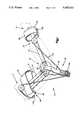
- FIG. 1is a perspective view of an adjustable orthosis embodying the present invention shown in a flexed position on an arm of a patient and set up to extend an elbow joint;
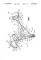
- FIG. 2is a view of the orthosis of FIG. 1 removed from the arm of the patient;
- FIG. 3is a view of the orthosis of FIG. 1 in an extended position
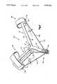
- FIG. 4is an enlarged view partially in section of the winch mechanism of the orthosis of FIG. 1;
- FIG. 5is a perspective view of an adjustable orthosis in accordance with a second embodiment of the present invention and shown in a flexed position;
- FIG. 6is a view of the orthosis of FIG. 5 in an extended position
- FIG. 7is a view of the orthosis of FIG. 1 set up to flex a joint
- FIG. 8is an enlarged view of an adjustable length support member for an adjustable orthosis in accordance with a third embodiment of the present invention.
- FIG. 9is an enlarged view of a portion of an orthosis with another adjustable length support member.
- FIG. 10is a view of the orthosis of FIG. 9 set up to flex a joint.
- the term "orthosis"is typically used to refer to a brace or other device applied to a portion of the body to correct malalignment of joints.
- the present inventionis an adjustable orthosis for stretching tissue in the human body.
- the present inventionrelates to an adjustable orthosis which can be used for stretching tissue in a body.
- the inventionis described as embodied in an orthosis for stretching tissue around a joint, although the invention is not limited thereto.
- FIG. 1illustrates an orthosis 10 in accordance with the present invention on a human limb including an upper arm 12 and a forearm 14 pivotally connected at an elbow joint 16.
- the orthosis 10is illustrated as set up to extend (straighten) the elbow joint 16, although it should be understood that the orthosis 10 can also be set up to flex (bend) the elbow joint 16, as will be described later.
- the orthosis 10can be used to extend or flex other joints in the body, such as a knee joint or a wrist joint or ankle joint, with the construction of the orthosis 10 in such case being varied to fit the particular application.
- the orthosiscan be used, for example, to flex the ankle joint to stretch a tight achilles tendon.
- the orthosiscan be custom made to fit a particular individual, or can be an off the shelf item.
- the orthosiscan also be used, for example, to eliminate contractures or stress soft tissue. It can be used for patients with cerebral palsy, stroke, spastic paralysis, as well as in post-traumatic or post-surgical cases. It can also be used, for example, in therapy after a knee replacement, in which the last five to ten degrees of motion is difficult to obtain without extensive intervention of a therapist.
- the orthosis 10includes a first arm assembly 18, a second arm assembly 20, and an actuator assembly 22 operable to pivot the first arm assembly 18 relative to the second arm assembly 20 to move the joint 16.
- move a jointmeans either to extend the joint or to flex the joint.
- the first arm assembly 18includes a rigid longitudinally extending arm 24 (FIGS. 1 and 2). To the outer end portion 26 of the arm 24 is attached a first cuff assembly 28.
- the first cuff assembly 28includes a rigid cuff portion 30 and a flexible cuff portion 32.
- the rigid cuff portion 30extends approximately halfway circumferentially about the upper arm 12, and the flexible cuff portion 32 wraps about the remainder of the upper arm 12.
- Suitable fastening meanssuch as Velcro® is used to secure the first cuff assembly 28 to the upper arm 12 so that the first arm assembly 18 may apply torque to the upper arm 12.
- the first arm assembly 18also includes a rigid longitudinally extending arm 40, which is shown in FIG. 2 but not in FIG. 1 as it is behind the upper arm 12.
- An outer end portion 42 of the arm 40is also attached to the rigid cuff portion 30 of the first cuff assembly 28.
- the arm 40extends parallel to the arm 24 and is spaced apart from the arm 24, with the arms 24 and 40 on opposite sides of the upper arm 12 of the limb.
- the second arm assembly 20includes a rigid longitudinally extending arm 44. To an outer end portion 46 of the arm 44 is attached a second cuff assembly 48.
- the second cuff assemblyincludes a rigid cuff portion 50 and a flexible cuff portion 52 attached thereto.
- the rigid cuff portion 50extends approximately halfway about the forearm 14, and the flexible cuff portion 52 wraps about the remainder of the forearm 14.
- Suitable fastening meanssuch as Velcro® is used to secure the second cuff assembly 48 about the forearm 14, so that the second arm assembly 20 can apply torque to the forearm 14.
- the second arm assembly 20also includes a rigid longitudinally extending arm 54 which is shown in FIG. 2 but not in FIG. 1.
- This arm 54extends parallel to and spaced apart from the arm 44, with the arms 54 and 44 on opposite sides of the forearm 14.
- An outer end portion 56 of the arm 54is attached to the rigid cuff portion 50.
- the actuator assembly 22includes a tower 82 which is provided to move the force generating point (that is, the point from which force is directed to the arm assemblies) away from the axis of rotation of the joint to obtain a mechanical advantage.
- the towercan be any structure which preforms this structure, and need not be the structure shown herein.
- the tower 82has a tower connecting portion 62 to which the inner end portions 64 and 66 of the arms 44 and 24 respectively are connected.
- On the back of the arms 44 and 24 as viewed in FIG. 2is a pivot plate (not shown) which is fixed by a rivet 68 to the tower connecting portion 62.
- the tower connecting portion 62 and the pivot platesecure the arm 24 for pivotal movement about a pivot point 70, and the arm 44 for pivotal movement about a pivot 72.
- the towerincludes a second tower portion 76 which joins the arms 40 and 54.
- An inner pivot plate 78is fixed via a rivet 80 to the second tower portion 76 and provides for pivotal movement of the arms 40 and 54 relative
- first tower portion 74 and the second tower portion 76which form the tower 82, support a winch 84 at a substantial distance from the pivot points 70 and 72 of the arms 24 and 44, and at a substantial distance from the pivot points of the arms 40 and 54.
- substantiallyis meant far enough to provide a mechanical advantage as compared to orthoses which apply force at a location adjacent the axis of rotation of the joint. The benefit of this is discussed later herein.
- the upper arm 12, elbow joint 16, and forearm 14define on one side of the joint 16 an inner sector "B" (inside the bend of the limb) which decreases in angle as the joint 16 is flexed.
- the upper arm 12, the elbow joint 16, and the forearm 14define on the opposite side of the joint 16 an outer sector "A" which decreases in angle as the joint 16 is extended (straightened).
- the tower 82 and the winch 84are located in the outer sector "A".
- the winch 84includes a drive member 86 (FIG. 4) which extends between the tower portion 76 and the tower portion 74.
- One end of the drive member 86is received in a bearing 88 in an opening in the tower portion 76, and the opposite end of the drive member 86 is received in a bearing 90 in a corresponding opening in the tower portion 74.
- a drum 92is fixed by a pin 94 to the drive member 86.
- Wrenching flats 96are formed on one end of the drive member 86.
- the opposite end of the drive member 86is received in a ratchet drive 98 which includes a pawl trigger 100.
- a leg portion 102 of the ratchet drive 98is fixed via a suitable fastener such as a screw 104 to the tower portion 76.
- a flexible member 110(FIG. 2) is included in the actuator assembly 22.
- the flexible member 110is a rope.
- a first end portion 112 of the rope 110terminates in clip 114 which is fixed via a pin 116 to the rigid cuff portion 30 of the first arm assembly 18.
- a portion 118 of the rope 110wraps around a pulley 120.
- a portion 122 of the ropeextends from the pulley 120 to the winch 84.
- the rope 110then wraps around the pin 94 (FIG. 4) as at 124 and a portion 126 of the rope 110 extends thence to a pulley 128 on the second arm assembly.
- a portion 130 of the ropewraps around the pulley 128.
- the other end portion 132 of the rope 110terminates in a clip 134 fixed by a pin 136 to the rigid cuff portion 50 of the second cuff assembly 48.
- both ends of the rope 110are fixed to the cuff assemblies, while the middle portion of the rope 110 is windable by the winch 84.
- the orthosis 10is operated to extend a joint such as the joint 16 in the following manner.
- the first cuff assembly 28is fastened about the upper arm 12 tightly enough that the first arm assembly 18 may apply torque to the upper arm 12 without having the cuff assembly 28 slide along the upper arm 12.
- the second cuff assembly 48is fastened securely around the forearm 14 so that the second arm assembly 20 may apply torque to the forearm 14 without the cuff assembly 48 sliding along the forearm 14.
- the drive member 86 of the winch 84is then rotated about its axis 106 to wind the rope 110.
- the rope portions 122 and 126are partially wound onto the drum 92.
- the cuff assemblies 28 and 48are drawn toward the winch 84.
- the first arm assembly 18pivots about the pivot point 70
- the second arm assembly 20pivots about the pivot point 72.
- the upper arm 12 and forearm 14, to which they are attachedalso pivot. This moves or extends the joint 16 as was desired.
- the acute angle ⁇ 2(FIG. 2) between the rope portion 122 and the first arm assembly 18 increases.
- the acute angle ⁇ 1(FIG. 2) between the rope portion 126 and the second arm assembly 20 also increases as the orthosis i adjusted from the relatively flexed position shown in FIG. 2 to the relatively extended position shown in FIG. 3.
- the torque applied by a cuff assembly to its respective limb portionis equal to (1) the force applied along the rope portion extending from the winch 84 to that arm assembly, times (2) the length of the lever arm of that arm assembly, times (3) the sine of the angle between the rope portion and the arm assembly.
- the torque applied to the first arm assembly 18 at the pulley 120is equal to the force applied along the rope portion 122, times the lever arm (which is equal to the distance between the pivot 70 and the pulley 120), times the sine of the angle ⁇ 1 between the rope portion 122 and the arm 24 or the arm 40.
- the angle between a rope portion (122 or 126) and its respective arm assembly (18 or 20)increases.
- the sine of the angle between the rope portion and the arm assemblyalso increases.
- the length of the lever armis a constant.
- the orthosis of the present inventionis highly advantageous in that the amount of torque available to pivot the upper arm relative to the forearm increases as the joint is extended.
- the orthosisprovides a large straightening force through the full range of motion because it maintains a significant vertical (extension) force vector through the full range of motion.
- thisassumes a sufficient force applied to and by the winch 84, and it is understood that more force may be needed to turn the winch 84 as the joint is fully extended to overcome the stiffness of the joint.
- the force vector representative of the pulling force extending along the flexible member 110can be resolved into a component extending in a direction parallel to the arm assembly and a component extending in a direction perpendicular to the arm assembly.
- the force component extending in the direction perpendicular to the arm assemblyis representative of the magnitude of the net extension force applied to the arm assembly to extend the joint. This component is equal to the sine of the angle between the flexible member and the arm assembly, times the force in the direction along the flexible member.
- the net extension forceis therefore directly proportional to the sine of the angle between the flexible member and the arm assembly.
- the anglecan be increased. It can be seen that one way to increase the angle is to increase the distance between the pivot point for the arm assembly and the drive means. Thus, it is evident that the longer the support member or tower, the greater the extension force.
- the structure of the orthosis 10is clearly advantageous as compared to, for example, a prior art device which applies its force at a location closely adjacent to the joint.
- the distance between the force application point and the pivot point of the armis very short.
- the angle between (a) the arm and (b) a line extending between the cuff assembly and the force generation pointis always extremely small. Accordingly, the amount of torque which can be generated is extremely limited.
- having the winch or drive means 84 spaced at a substantial distance from the pivot points 70 and 72 by the tower 82, as in the illustrated embodiments,provides a substantial mechanical advantage.
- the pulley 120is in a different position on the first arm assembly 18 than the pulley 128 is on the second arm assembly 20.
- the location of the pulleysis a matter of design choice. As a pulley is moved farther out along its arm assembly from the pivot point, the lever arm and thus the torque applied to the arm assembly by the winch 84 pulling on the flexible member 110 increases.
- the pulleyis also preferably located as far from the rope end portions as possible in a direction transverse to the longitudinal extent of the arms. For example, the pulley 120 is farther from the pin 116 in a direction transverse to the arm 24, than the pulley 128 is from the pinion 136 in a direction transverse to the arm 44. Moving the pulley farther away in this manner increases the angle between the rope portions and the arm assemblies, thus increasing the available torque.
- the orthoses of the present inventionare suitable to hyperextend a joint, also.
- the orthosisis constructed so that the joint when fully extended is hyperextended by 5° to 7°. This provides the fullest range of motion desired. This can be accomplished by construction of the pivotal connection between the arm assemblies to allow for such hyperextension.
- FIGS. 5 and 6A second embodiment of the invention is illustrated in FIGS. 5 and 6, in which parts which are the same as in the first embodiment are given the same reference numerals.
- An orthosis 140includes a flexible member 110 which does not extend around pulleys but extends directly from the winch 84 to the cuff assemblies 28 and 48.
- the orthosis 140is, like the orthosis 110, adjustable between a relatively flexed position as viewed in FIG. 5 and a relatively extended position as viewed in FIG. 6.
- Manual actuation of the winch 84draws or pulls the rope portions 122 and 126 to wind them on the winch 84, shortening the distance between the cuff assemblies 28 and 48 and the winch 84. Because the inner ends of the arms 24, 40, 44, and 54 are pivotally mounted to the tower 82, the arm assemblies 18 and 20 pivot relative to each other to move the joint 16 into a more extended position.
- the acute angle ⁇ 1 between the rope portion 126 and the second arm assembly 120, and the acute angle ⁇ 2 between the rope portion 122 and the first arm assembly 18,increase in degree as the orthosis 140 is adjusted from the more flexed position shown in FIG. 5 to the more extended position shown in FIG. 6.
- placement of the winch or drive means 84 at substantial distance from the pivot points 70 and 72, as in the embodiment illustrated in FIGS. 5 and 6,ensures that a significant mechanical advantage is obtained.
- the orthosis 10is illustrated in FIGS. 1 through 4 as being used to extend a joint.
- the orthosis 10can also be used to flex a joint as illustrated in FIG. 7. This is done by rerouting the flexible member 110.
- the end portion 132 (FIG. 7) of the flexible member 110remains fixed by the pin 136 to the second cuff assembly 48.
- a portion 150 of the rope 110then extends underneath the pulley 128 over to the pulley 120.
- the rope 110then extends around the pulley 120 and a portion 152 of the rope 110 extends to the winch 84.
- the end portion 112 of the rope 110is tied or otherwise fixed to the winch 84.
- the winch 84When the winch 84 is then manually operated, the rope 110 will be wound to the drum of the winch 84.
- the second cuff assembly 48will be drawn toward the first cuff assembly 28. Because the inner ends of the arm assemblies 18 and 20 are fixed to the tower 82 the arm assemblies 18 and 20 pivot relative to each other, decreasing the included angle between them. Since the arm assemblies 18 and 20 are fixed to the limb portions 12 and 14, the joint 16 is flexed.
- the actuator assembly for pivoting the first and second arm assemblies 18 and 20includes, in place of the tower 82 and the winch 84, a variable length tower with a pulley at its outer end. Extending the variable length tower to move the pulley farther away from the pivot points of the arm assemblies 18 and 20, causes the arm assemblies 18 and 20 to pivot relative to each other to flex the joint 16.
- variable length feature of the tower assemblycan be obtained in many different ways.
- FIGS. 8 and 9illustrate two ways of constructing the variable length tower assembly.
- a tower assembly 160includes a fixed portion 162 (only a part of which is shown) upon which the arm assemblies 18 and 20 (not shown) are pivoted.
- a tower portion 164is movable axially relative to the fixed tower portion 162.
- a pneumatic ram assembly 166is actuatable in an axial direction as indicated by arrow 168 upon the introduction of fluid under pressure through a fluid supply line 170.
- a pulley(not shown) is mounted for rotation on the outward end of the movable tower portion 164.
- a flexible member or rope 110passes over the pulley and is not fixed to the pulley 172.
- the pneumatic ram assembly 166Upon the introduction of fluid under pressure through the fluid supply line 170, the pneumatic ram assembly 166 causes the movable tower portion 164 to move outwardly relative to the fixed tower portion 162. Such motion causes the pulley to move away from the pivot points for the arm assemblies 18 and 20. This exerts a pulling force on the flexible member which extends around the pulley. This pulling force, as above, causes the arm assemblies 18 and 20 to pivot relative to each other to extend the joint 16 to which the orthosis is attached.
- Fluid under pressuremay be supplied to the supply line 170 in any known manner.
- One specific apparatuswhich is operable by hand and thus usable by the patient, is illustrated in FIG. 8 and includes a piston 174 disposed within a chamber 176.
- An arm 178connects the piston 174 to a handle 180 which is pivotally mounted at 182 to a base 184.
- the handle 180is moved (squeezed) toward the base 184 in the direction indicated by arrow 186, the piston 174 forces air through the fluid supply line to supply the pneumatic ram assembly 166.
- any means of supply fluid under pressurecould suitably also be used.
- the tower assembly 190includes a fixed tower portion 192 having a threaded member 194 projecting outwardly therefrom, and a movable tower portion 196 having a threaded member 198 projecting inwardly therefrom.
- a sleeve nut 200threadedly engages the threaded members 194 and 198 and has a handle portion or thumbwheel 202 extending radially therefrom.
- a pulley(not shown) is mounted on the movable tower portion 196 as in the construction illustrated in FIG. 8.
- the fixed tower portion 192is connected to the first and second arm assemblies.
- FIG. 10illustrates such a construction.
- the one end portion 132 of the rope 110is fixed to one cuff assembly 40.
- the opposite end portion 112 of the rope 110is fixed to an outer end 206 of the extendible tower 204.
- the extendible tower assembly 204 of the orthosis shown in FIG. 10is made longer, increasing the distance between the pulley 206 and the pivotal connection with the arm assemblies 18 and 20, a pulling force is generated on the rope portion 208, drawing the cuff assemblies 28 and 40 closer to each other.
- the extendible tower assemblyis usable in both flexion and extension modes, just as the tower with a winch or other type of drive means is usable in both flexion and extension modes.
- the illustrated orthosesmay also include means for monitoring the amount of force transmitted through the flexible member 110 to the arm assemblies 18 and 20. Further, the orthoses may include relief means for limiting the amount of force transmitted to the arms 18 and 10. Such means are indicated schematically at 210 in FIG. 4 as being in the line of force transmission between the drive member 86 and an extension 216 thereof.
- the force monitoring or limiting meanscan be something as simple as a torque wrench applied to the drive member 86, or it can be a more complex mechanical structure, or it can be electronically controlled or operated.
- the box 210illustrates schematically the provision or placement of force measuring and/or limiting means within the force path between the point at which the actuator is manually actuated and the cuff assemblies which transmit force to the arm portion.
- Such meanscan also be included, for example, within the flexible member itself, or at the pivot points, or at any other suitable location. Provision of such force monitoring or limiting means is within the skill of the art and thus is not described further herein.
- the arms 24, 40, 44, and 54are rigid members made of, for example, aluminum or stainless steel.
- the armsare rigid so as to be able to transmit the necessary forces.
- the tower 82 and any extensible toweris also made of suitable material such as aluminum or stainless steel in order to provide a rigid structure capable of transmitting the necessary forces. It should be understood that any material of sufficient rigidity can be used, including a polymeric or composite material.
- the winch 84is not the only possible mechanism which can be used for tightening the flexible member 110. Rather, any other suitable mechanism can be used for that purpose, such as a screw mechanism, a pneumatic or fluid operated mechanism, a motor drive, etc. Furthermore, any structure other than the tower 82 can be employed, which will move the point of force application away from the axis of rotation of the joint. Again, the hinge structure shown can, of course, be replaced by, for example, a flexible piece of plastic or some other hinge mechanism. Accordingly, the present invention is not limited to the use of a winch or a tower or hinge strictly as shown.
- the flexible member 110can include or can be replaced by a resilient member, such as an elastic portion or a spring loading structure.
- a resilient membersuch as an elastic portion or a spring loading structure. This provides the patient with some ability to bend or flex the joint while the orthosis is attempting to extend the joint. In effect, the patient's muscles work against the force of the orthosis and providing further exercise for the muscles.
- the flexible memberwhen tensioned by the drive means, is stretched even more by the patient pulling on it in the opposite direction--resisting the extension force applied by the winch. He pulls through the range of motion. After the range of motion is obtained, the device can also be used for exercise, to lessen pain, and to retain the range of motion at any given point.
- any of the orthoses of the present inventionmay also include means for providing three distinct areas of application of force to the limb.
- meanscan be provided for applying force in the opposite direction to the area of the limb adjacent the joint. This would include, for example, a cup on the outside of the elbow or knee or straps extending around the elbow or knee.
- Such modificationcan easily be made in accordance with the teachings of the prior art, for example as shown in the Best, Brown, or Lonardo patents identified above.
Landscapes
- Health & Medical Sciences (AREA)
- Nursing (AREA)
- Orthopedic Medicine & Surgery (AREA)
- Engineering & Computer Science (AREA)
- Biomedical Technology (AREA)
- Heart & Thoracic Surgery (AREA)
- Vascular Medicine (AREA)
- Life Sciences & Earth Sciences (AREA)
- Animal Behavior & Ethology (AREA)
- General Health & Medical Sciences (AREA)
- Public Health (AREA)
- Veterinary Medicine (AREA)
- Prostheses (AREA)
- Orthopedics, Nursing, And Contraception (AREA)
Abstract
Description
Claims (37)
Priority Applications (11)
| Application Number | Priority Date | Filing Date | Title |
|---|---|---|---|
| US07/559,700US5167612A (en) | 1990-07-30 | 1990-07-30 | Adjustable orthosis |
| US07/686,811US5213094A (en) | 1990-07-30 | 1991-04-17 | Orthosis with joint distraction |
| US07/690,845US5285773A (en) | 1990-07-30 | 1991-04-24 | Orthosis with distraction through range of motion |
| CA002065669ACA2065669C (en) | 1990-07-30 | 1992-04-09 | Adjustable orthosis |
| EP92303251AEP0564734A1 (en) | 1990-07-30 | 1992-04-10 | Adjustable orthosis |
| US07/978,103US5365947A (en) | 1990-07-30 | 1992-11-18 | Adjustable orthosis |
| US08/293,035US5456268A (en) | 1990-07-30 | 1994-08-19 | Adjustable orthosis |
| US08/297,258US5453075A (en) | 1990-07-30 | 1994-08-26 | Orthosis with distraction through range of motion |
| US08/306,619US5503619A (en) | 1990-07-30 | 1994-09-15 | Orthosis for bending wrists |
| US08/458,982US5611764A (en) | 1990-07-30 | 1995-06-02 | Method of increasing range of motion |
| US08/488,194US5685830A (en) | 1990-07-30 | 1995-06-07 | Adjustable orthosis having one-piece connector section for flexing |
Applications Claiming Priority (2)
| Application Number | Priority Date | Filing Date | Title |
|---|---|---|---|
| US07/559,700US5167612A (en) | 1990-07-30 | 1990-07-30 | Adjustable orthosis |
| CA002065669ACA2065669C (en) | 1990-07-30 | 1992-04-09 | Adjustable orthosis |
Related Parent Applications (1)
| Application Number | Title | Priority Date | Filing Date |
|---|---|---|---|
| US07/686,811Continuation-In-PartUS5213094A (en) | 1990-07-30 | 1991-04-17 | Orthosis with joint distraction |
Related Child Applications (3)
| Application Number | Title | Priority Date | Filing Date |
|---|---|---|---|
| US07/686,811Continuation-In-PartUS5213094A (en) | 1990-07-30 | 1991-04-17 | Orthosis with joint distraction |
| US07/690,845Continuation-In-PartUS5285773A (en) | 1990-07-30 | 1991-04-24 | Orthosis with distraction through range of motion |
| US07/978,103DivisionUS5365947A (en) | 1990-07-30 | 1992-11-18 | Adjustable orthosis |
Publications (1)
| Publication Number | Publication Date |
|---|---|
| US5167612Atrue US5167612A (en) | 1992-12-01 |
Family
ID=25675074
Family Applications (3)
| Application Number | Title | Priority Date | Filing Date |
|---|---|---|---|
| US07/559,700Expired - LifetimeUS5167612A (en) | 1990-07-30 | 1990-07-30 | Adjustable orthosis |
| US07/978,103Expired - LifetimeUS5365947A (en) | 1990-07-30 | 1992-11-18 | Adjustable orthosis |
| US08/293,035Expired - LifetimeUS5456268A (en) | 1990-07-30 | 1994-08-19 | Adjustable orthosis |
Family Applications After (2)
| Application Number | Title | Priority Date | Filing Date |
|---|---|---|---|
| US07/978,103Expired - LifetimeUS5365947A (en) | 1990-07-30 | 1992-11-18 | Adjustable orthosis |
| US08/293,035Expired - LifetimeUS5456268A (en) | 1990-07-30 | 1994-08-19 | Adjustable orthosis |
Country Status (3)
| Country | Link |
|---|---|
| US (3) | US5167612A (en) |
| EP (1) | EP0564734A1 (en) |
| CA (1) | CA2065669C (en) |
Cited By (58)
| Publication number | Priority date | Publication date | Assignee | Title |
|---|---|---|---|---|
| US5372597A (en)* | 1993-05-12 | 1994-12-13 | Smith & Nephew Richards, Inc. | Supination-pronation device |
| WO1995001141A1 (en)* | 1993-06-30 | 1995-01-12 | Empi, Inc. | Constant torque range-of-motion splint |
| US5407420A (en)* | 1992-11-12 | 1995-04-18 | Smith & Nephew Donjoy, Inc. | Fully adjustable shoulder brace |
| US5437619A (en)* | 1993-06-30 | 1995-08-01 | Empi, Inc. | Range-of-motion splint with eccentric spring |
| US5520627A (en)* | 1993-06-30 | 1996-05-28 | Empi, Inc. | Range-of-motion ankle splint |
| WO1996016615A1 (en)* | 1994-11-30 | 1996-06-06 | Tagg Industries | External ligament system |
| US5571078A (en)* | 1993-06-30 | 1996-11-05 | Empi, Inc. | Range-of-motion ankle splint |
| US5611764A (en)* | 1990-07-30 | 1997-03-18 | Peter M. Bonutti | Method of increasing range of motion |
| US5891061A (en)* | 1997-02-20 | 1999-04-06 | Jace Systems, Inc. | Brace for applying a dynamic force to a jointed limb |
| US6110138A (en)* | 1999-02-01 | 2000-08-29 | Tagg Industries, L.L.C. | Stance-correcting knee brace |
| US6537237B1 (en) | 2001-09-28 | 2003-03-25 | R & R Holdings, Llc | Orthotic device |
| US20030125651A1 (en)* | 2001-12-31 | 2003-07-03 | R & R Holdings, Llc | Supination/pronation therapy device |
| US20030144620A1 (en)* | 2001-09-28 | 2003-07-31 | Sieller Richard T. | Orthotic device |
| US20040215111A1 (en)* | 2003-04-23 | 2004-10-28 | Bonutti Peter M. | Patient monitoring apparatus and method for orthosis and other devices |
| US6821262B1 (en) | 2001-08-31 | 2004-11-23 | Richard R. Muse | Self operable knee extension therapy device |
| US20050059908A1 (en)* | 2003-09-11 | 2005-03-17 | The Cleveland Clinic Foundation | Apparatus for assisting body movement |
| US20060106328A1 (en)* | 2004-11-12 | 2006-05-18 | Sieller Richard T | Flexion and extension device |
| US20060258965A1 (en)* | 2003-03-24 | 2006-11-16 | Lee Michael J | Dynamic supinated splint |
| WO2007051168A2 (en) | 2005-10-28 | 2007-05-03 | Bonutti Research Inc. | Range of motion device |
| WO2008036895A2 (en) | 2006-09-21 | 2008-03-27 | Marctec, Llc | Range of motion device |
| WO2008097989A2 (en) | 2007-02-05 | 2008-08-14 | Bonutti Research Inc. | Knee orthosis |
| US7473234B1 (en) | 2004-05-24 | 2009-01-06 | Deroyal Industries, Inc. | Brace with worm gear |
| WO2009015364A1 (en) | 2007-07-25 | 2009-01-29 | Bonutti Research Inc. | Orthosis apparatus and method of using an orthosis apparatus |
| US20100049110A1 (en)* | 2008-08-21 | 2010-02-25 | Christophe Blanchard | Extremity Support Apparatus and Method |
| US7955285B2 (en) | 1998-06-01 | 2011-06-07 | Bonutti Research Inc. | Shoulder orthosis |
| US8012108B2 (en) | 2005-08-12 | 2011-09-06 | Bonutti Research, Inc. | Range of motion system and method |
| US8038637B2 (en) | 2000-09-18 | 2011-10-18 | Bonutti Research, Inc. | Finger orthosis |
| US8062241B2 (en) | 2000-12-15 | 2011-11-22 | Bonutti Research Inc | Myofascial strap |
| US8066656B2 (en) | 2005-10-28 | 2011-11-29 | Bonutti Research, Inc. | Range of motion device |
| US8251934B2 (en) | 2000-12-01 | 2012-08-28 | Bonutti Research, Inc. | Orthosis and method for cervical mobilization |
| US8277401B2 (en) | 2006-09-12 | 2012-10-02 | Boa Technology, Inc. | Closure system for braces, protective wear and similar articles |
| US8424168B2 (en) | 2008-01-18 | 2013-04-23 | Boa Technology, Inc. | Closure system |
| US8468657B2 (en) | 2008-11-21 | 2013-06-25 | Boa Technology, Inc. | Reel based lacing system |
| US20130296757A1 (en)* | 2010-12-15 | 2013-11-07 | Wieland Kaphingst | Orthosis for movement damping |
| US8905950B2 (en) | 2008-03-04 | 2014-12-09 | Bonutti Research, Inc. | Shoulder ROM orthosis |
| CN104203165A (en)* | 2011-10-31 | 2014-12-10 | 奥索有限责任公司 | Orthopedic device for dynamically treating the knee |
| US20150119998A1 (en)* | 2012-06-04 | 2015-04-30 | Commissariat a L"energie atomique et aux energies alternatives | Exoskeleton arm having an actuator |
| US9149089B2 (en) | 2010-07-01 | 2015-10-06 | Boa Technology, Inc. | Lace guide |
| US9179729B2 (en) | 2012-03-13 | 2015-11-10 | Boa Technology, Inc. | Tightening systems |
| US20150335458A1 (en)* | 2012-03-13 | 2015-11-26 | Ossur Hf | Patellofemoral device and method for using the same |
| US9402759B2 (en) | 2013-02-05 | 2016-08-02 | Bonutti Research, Inc. | Cervical traction systems and method |
| WO2016126584A1 (en)* | 2015-02-02 | 2016-08-11 | Ossur Iceland Ehf | Orthopedic device |
| WO2017105232A1 (en)* | 2015-12-15 | 2017-06-22 | Academisch Medisch Centrum | Device and method for determination of the moment-induced movement of a joint implant |
| US20170209330A1 (en)* | 2015-07-17 | 2017-07-27 | Ekso Bionics, Inc. | Universal tensegrity joints for human exoskeleton |
| CN109925165A (en)* | 2019-02-28 | 2019-06-25 | 浙江工业大学 | " 4+2 " formula lower limb rehabilitation robot based on rope driving |
| CN109925164A (en)* | 2019-02-28 | 2019-06-25 | 浙江工业大学 | The Nei Zu mechanism based on rope driving for lower limb rehabilitation robot |
| US10499709B2 (en) | 2016-08-02 | 2019-12-10 | Boa Technology Inc. | Tension member guides of a lacing system |
| US20200121478A1 (en)* | 2017-06-19 | 2020-04-23 | Tendo Ab | Device for moving an arm and a method of operating the device |
| US10966854B1 (en)* | 2019-09-04 | 2021-04-06 | Brice W Lockart | Brace with a variable resistance band system |
| CN113520806A (en)* | 2021-08-20 | 2021-10-22 | 电子科技大学 | Biomimetic tensioning overall multi-degree-of-freedom self-supporting flexible ankle joint wearing assist device |
| US20220031551A2 (en)* | 2018-11-05 | 2022-02-03 | Ottobock Se & Co. Kgaa | Device for supporting at least one arm of a user and for supporting at least one upper arm |
| US11253385B1 (en) | 2019-06-21 | 2022-02-22 | Brice W Lockart | Brace with resistance band |
| US11297903B2 (en) | 2011-10-13 | 2022-04-12 | Boa Technology, Inc. | Reel-based lacing system |
| US11497642B2 (en) | 2019-01-30 | 2022-11-15 | Ossur Iceland Ehf | Orthopedic device for patellofemoral issues |
| CN116115421A (en)* | 2023-04-12 | 2023-05-16 | 四川省医学科学院·四川省人民医院 | Temperature-controlled venous thrombosis prevention sheath |
| US11896538B2 (en)* | 2013-03-15 | 2024-02-13 | Ermi, Inc. | Device with therapeutic features |
| US12144401B2 (en) | 2013-06-05 | 2024-11-19 | Boa Technology, Inc. | Integrated closure device components and methods |
| US12256803B2 (en) | 2019-02-01 | 2025-03-25 | Boa Technology Inc. | Reel based closure devices for tightening a ski boot |
Families Citing this family (85)
| Publication number | Priority date | Publication date | Assignee | Title |
|---|---|---|---|---|
| US5575764A (en)* | 1994-12-14 | 1996-11-19 | Van Dyne; Leonard A. | Prosthetic joint with dynamic torque compensator |
| CN1074614C (en)* | 1997-03-04 | 2001-11-07 | 中国科学院空间科学与应用研究中心 | Device for production of nanosecond modulated narrow pulse |
| US7163113B2 (en)* | 2000-04-05 | 2007-01-16 | Playtex Products, Inc. | Vent disc with center knob |
| US6702821B2 (en) | 2000-01-14 | 2004-03-09 | The Bonutti 2003 Trust A | Instrumentation for minimally invasive joint replacement and methods for using same |
| US7104996B2 (en) | 2000-01-14 | 2006-09-12 | Marctec. Llc | Method of performing surgery |
| US6770078B2 (en) | 2000-01-14 | 2004-08-03 | Peter M. Bonutti | Movable knee implant and methods therefor |
| US7635390B1 (en) | 2000-01-14 | 2009-12-22 | Marctec, Llc | Joint replacement component having a modular articulating surface |
| US6530868B1 (en)* | 2000-03-27 | 2003-03-11 | Leslie Pape | Exercise device |
| US6506172B1 (en) | 2000-10-10 | 2003-01-14 | Dynasplint Systems, Inc. | Supinator/pronator therapy system to bring mobility to wrist, forearm and/or elbow |
| US7708741B1 (en) | 2001-08-28 | 2010-05-04 | Marctec, Llc | Method of preparing bones for knee replacement surgery |
| DE20117080U1 (en) | 2001-10-17 | 2002-01-24 | Jacobs, Klaus-Jürgen, 64546 Mörfelden-Walldorf | Quengel orthosis |
| AU2003225075A1 (en)* | 2002-04-16 | 2003-11-03 | Sean K. Scorvo | An adjustable orthotic brace |
| US7837690B2 (en) | 2003-01-15 | 2010-11-23 | Biomet Manufacturing Corp. | Method and apparatus for less invasive knee resection |
| US7887542B2 (en) | 2003-01-15 | 2011-02-15 | Biomet Manufacturing Corp. | Method and apparatus for less invasive knee resection |
| US7789885B2 (en) | 2003-01-15 | 2010-09-07 | Biomet Manufacturing Corp. | Instrumentation for knee resection |
| US8551100B2 (en) | 2003-01-15 | 2013-10-08 | Biomet Manufacturing, Llc | Instrumentation for knee resection |
| US7488324B1 (en) | 2003-12-08 | 2009-02-10 | Biomet Manufacturing Corporation | Femoral guide for implanting a femoral knee prosthesis |
| US7112179B2 (en) | 2004-03-08 | 2006-09-26 | Marc Tec, Llc | Orthosis |
| US7524294B1 (en) | 2004-08-24 | 2009-04-28 | Shelton Jean E | Arm lift flexion device |
| US7695479B1 (en) | 2005-04-12 | 2010-04-13 | Biomet Manufacturing Corp. | Femoral sizer |
| US9289253B2 (en) | 2006-02-27 | 2016-03-22 | Biomet Manufacturing, Llc | Patient-specific shoulder guide |
| US8591516B2 (en) | 2006-02-27 | 2013-11-26 | Biomet Manufacturing, Llc | Patient-specific orthopedic instruments |
| US8070752B2 (en) | 2006-02-27 | 2011-12-06 | Biomet Manufacturing Corp. | Patient specific alignment guide and inter-operative adjustment |
| US7780672B2 (en) | 2006-02-27 | 2010-08-24 | Biomet Manufacturing Corp. | Femoral adjustment device and associated method |
| US8603180B2 (en) | 2006-02-27 | 2013-12-10 | Biomet Manufacturing, Llc | Patient-specific acetabular alignment guides |
| US20150335438A1 (en) | 2006-02-27 | 2015-11-26 | Biomet Manufacturing, Llc. | Patient-specific augments |
| US9339278B2 (en) | 2006-02-27 | 2016-05-17 | Biomet Manufacturing, Llc | Patient-specific acetabular guides and associated instruments |
| US9918740B2 (en) | 2006-02-27 | 2018-03-20 | Biomet Manufacturing, Llc | Backup surgical instrument system and method |
| US8407067B2 (en) | 2007-04-17 | 2013-03-26 | Biomet Manufacturing Corp. | Method and apparatus for manufacturing an implant |
| US9907659B2 (en) | 2007-04-17 | 2018-03-06 | Biomet Manufacturing, Llc | Method and apparatus for manufacturing an implant |
| US10278711B2 (en) | 2006-02-27 | 2019-05-07 | Biomet Manufacturing, Llc | Patient-specific femoral guide |
| US9345548B2 (en) | 2006-02-27 | 2016-05-24 | Biomet Manufacturing, Llc | Patient-specific pre-operative planning |
| US9113971B2 (en) | 2006-02-27 | 2015-08-25 | Biomet Manufacturing, Llc | Femoral acetabular impingement guide |
| US9173661B2 (en) | 2006-02-27 | 2015-11-03 | Biomet Manufacturing, Llc | Patient specific alignment guide with cutting surface and laser indicator |
| US7695520B2 (en) | 2006-05-31 | 2010-04-13 | Biomet Manufacturing Corp. | Prosthesis and implementation system |
| US9795399B2 (en) | 2006-06-09 | 2017-10-24 | Biomet Manufacturing, Llc | Patient-specific knee alignment guide and associated method |
| US8265949B2 (en) | 2007-09-27 | 2012-09-11 | Depuy Products, Inc. | Customized patient surgical plan |
| US8357111B2 (en) | 2007-09-30 | 2013-01-22 | Depuy Products, Inc. | Method and system for designing patient-specific orthopaedic surgical instruments |
| EP2194889B1 (en) | 2007-09-30 | 2015-09-23 | DePuy Products, Inc. | Customized patient-specific orthopaedic surgical instrumentation |
| CN102026594B (en)* | 2008-05-15 | 2013-12-25 | 欧苏尔公司 | Orthopedic devices utilizing rotary tensioning |
| US8409117B2 (en)* | 2008-09-15 | 2013-04-02 | The Hong Kong Polytechnic University | Wearable device to assist with the movement of limbs |
| AT507806B1 (en)* | 2009-01-30 | 2011-07-15 | Ima Integrated Microsystems Austria Gmbh | retractor |
| CN102333502B (en) | 2009-02-26 | 2014-06-25 | 欧苏尔公司 | Orthopedic devices used to treat the back |
| US8657769B2 (en) | 2009-11-04 | 2014-02-25 | Ossur Hf | Thoracic lumbar sacral orthosis |
| EP2598087B1 (en)* | 2010-07-28 | 2015-03-25 | Indaco S.r.l. | Support for human joints |
| US9220624B2 (en) | 2010-09-16 | 2015-12-29 | Ossur Hf | Posterior cruciate ligament support brace |
| US9243965B2 (en)* | 2010-11-08 | 2016-01-26 | Tulsa Winch, Inc. | System and method for calculating winch line pull |
| US8882688B1 (en)* | 2010-11-15 | 2014-11-11 | Craig Ancinec | Orthotic joint stabilizing assembly |
| US9968376B2 (en) | 2010-11-29 | 2018-05-15 | Biomet Manufacturing, Llc | Patient-specific orthopedic instruments |
| CN103442669B (en) | 2011-02-10 | 2015-09-16 | 奥索有限责任公司 | For the tightening system of orthopedic goods |
| US9241745B2 (en) | 2011-03-07 | 2016-01-26 | Biomet Manufacturing, Llc | Patient-specific femoral version guide |
| US9114277B2 (en)* | 2011-04-13 | 2015-08-25 | Gregory William Goeckel | Exercise brace |
| WO2012177700A2 (en) | 2011-06-20 | 2012-12-27 | Ossur Hf | Orthopedic device, use of orthopedic device and method for producing the same |
| US9572705B2 (en) | 2012-01-13 | 2017-02-21 | Ossur Hf | Spinal orthosis |
| WO2013106666A1 (en) | 2012-01-13 | 2013-07-18 | Ossur Hf | Spinal orthosis and method for using the same |
| EP2897559B1 (en) | 2012-09-19 | 2019-03-06 | Ossur HF | Panel attachment and circumference adjustment systems for an orthopedic device |
| JP2014073222A (en)* | 2012-10-04 | 2014-04-24 | Sony Corp | Exercise assisting device, and exercise assisting method |
| US10357391B2 (en) | 2013-01-24 | 2019-07-23 | Ossur Hf | Orthopedic device for treating complications of the hip |
| WO2014116895A1 (en) | 2013-01-24 | 2014-07-31 | Ossur Hf | Orthopedic device for treating complications of the hip |
| US9795500B2 (en) | 2013-01-24 | 2017-10-24 | Ossur Hf | Orthopedic device for treating complications of the hip |
| US9554935B2 (en) | 2013-01-24 | 2017-01-31 | Ossur Hf | Orthopedic device for treating complications of the hip |
| US9539135B2 (en) | 2013-01-25 | 2017-01-10 | Ossur Hf | Orthopedic device having a dynamic control system and method for using the same |
| US10413437B2 (en) | 2013-01-25 | 2019-09-17 | Ossur Iceland Ehf | Orthopedic device having a dynamic control system and method for using the same |
| WO2014117109A1 (en) | 2013-01-25 | 2014-07-31 | Ossur Hf | Orthopedic device having a dynamic control system |
| WO2014205103A1 (en) | 2013-06-21 | 2014-12-24 | Ossur Hf | Dynamic tension system for orthopedic device |
| WO2015026889A1 (en) | 2013-08-22 | 2015-02-26 | Ossur Hf | Torque limiting tool and method for using the same |
| EP3134038A4 (en) | 2014-04-25 | 2017-11-29 | The Trustees of Columbia University in the City of New York | Spinal treatment devices, methods, and systems |
| WO2015179332A1 (en) | 2014-05-19 | 2015-11-26 | Ossur Hf | Adjustable prosthetic device |
| US10078923B2 (en) | 2014-06-06 | 2018-09-18 | Tulsa Winch, Inc. | Embedded hoist human-machine interface |
| WO2016007704A1 (en) | 2014-07-11 | 2016-01-14 | Ossur Hf | Tightening system with a tension control mechanism |
| EP3200733B1 (en) | 2014-10-01 | 2018-11-28 | Össur Iceland EHF | Support for articles and methods for using the same |
| WO2016069839A1 (en) | 2014-10-31 | 2016-05-06 | Ossur Hf | Orthopedic device having a dynamic control system |
| US10561520B2 (en) | 2015-02-27 | 2020-02-18 | Ossur Iceland Ehf | Spinal orthosis, kit and method for using the same |
| WO2016138215A1 (en) | 2015-02-27 | 2016-09-01 | Ossur Iceland Ehf | Spinal orthosis, kit and method for using the same |
| CN105055065B (en)* | 2015-04-28 | 2019-04-12 | 繁昌县倍思生产力促进中心有限公司 | A kind of unilateral plain type orthopaedic device for knee |
| CN104983498B (en)* | 2015-07-10 | 2017-05-31 | 哈尔滨天愈康复医疗机器人有限公司 | Rope type scoliosis rehabilitation medical robot |
| JP6935860B2 (en) | 2015-08-14 | 2021-09-15 | パヴィーニ、マリーPAVINI, Marie | Exercise restraint system and method for medical protection |
| US10722310B2 (en) | 2017-03-13 | 2020-07-28 | Zimmer Biomet CMF and Thoracic, LLC | Virtual surgery planning system and method |
| EP3678613B1 (en) | 2017-09-07 | 2023-08-09 | Össur Iceland EHF | Thoracic lumbar sacral orthosis attachment |
| US11000439B2 (en) | 2017-09-28 | 2021-05-11 | Ossur Iceland Ehf | Body interface |
| US11547590B2 (en) | 2017-11-27 | 2023-01-10 | Ossur Iceland Ehf | Orthopedic device having a suspension element |
| US11051829B2 (en) | 2018-06-26 | 2021-07-06 | DePuy Synthes Products, Inc. | Customized patient-specific orthopaedic surgical instrument |
| DE102018116569B3 (en) | 2018-07-09 | 2019-11-14 | Betterguards Technology Gmbh | Device for damping body movement via a body joint |
| EP3793493B1 (en) | 2019-04-26 | 2023-08-23 | MyoSwiss AG | Wearable assistive device |
| CN111888187B (en)* | 2020-07-24 | 2021-06-11 | 华中科技大学 | Active type knee hyperextension lower limb rehabilitation exoskeleton device |
Citations (17)
| Publication number | Priority date | Publication date | Assignee | Title |
|---|---|---|---|---|
| US3814419A (en)* | 1973-06-04 | 1974-06-04 | L Bjorklund | Arm exercising device |
| US4039183A (en)* | 1976-04-21 | 1977-08-02 | Ritshyo Kogyo Kabushiki Kaisha | Wrist exercise and strengthening device |
| US4180870A (en)* | 1975-04-15 | 1980-01-01 | Fa Wilh. Jul. Teufel | Universal-orthese |
| DE2829562A1 (en)* | 1978-07-05 | 1980-01-17 | Klaus Muenich | Machine for exercising part of human body - has motor reversing switch actuated by lever coupled to winch drum |
| US4237873A (en)* | 1978-12-11 | 1980-12-09 | Hoyt Laurance J Sr | Cerebral palsy arm and hand brace |
| US4441489A (en)* | 1981-03-10 | 1984-04-10 | National Research Development Corporation | Orthopaedic splints |
| US4456002A (en)* | 1982-09-27 | 1984-06-26 | L M B Hand Rehab Products | Spring metacarpophalangeal flexion splint (knuckle splint) |
| US4508111A (en)* | 1981-07-23 | 1985-04-02 | Dynasplint Systems, Inc. | Adjustable splint |
| US4538600A (en)* | 1983-10-27 | 1985-09-03 | Dynasplint Systems, Inc. | Adjustable splint |
| US4612919A (en)* | 1984-10-03 | 1986-09-23 | Best Walter E | Adjustable limb support |
| US4665905A (en)* | 1986-06-09 | 1987-05-19 | Brown Charles S | Dynamic elbow and knee extension brace |
| SU1426580A1 (en)* | 1987-02-04 | 1988-09-30 | Научно-исследовательский институт травматологии и ортопедии | Arrangement for mechanotherapy of fingers of the hand |
| US4790301A (en)* | 1987-10-23 | 1988-12-13 | Krister Silfverskiold | Device for and method of dynamic splinting |
| US4844454A (en)* | 1988-07-15 | 1989-07-04 | Rogers Stephen A | Portable, manually operable knee exerciser |
| US4848326A (en)* | 1988-06-20 | 1989-07-18 | Robert Lonardo | Knee contracture correction device |
| US4865024A (en)* | 1988-10-21 | 1989-09-12 | Hensley Dvid E | Extension deceleration orthosis |
| US4930497A (en)* | 1989-01-23 | 1990-06-05 | Toronto Medical Corp. | Apparatus for imparting continuous passive motion to a lower limb |
Family Cites Families (9)
| Publication number | Priority date | Publication date | Assignee | Title |
|---|---|---|---|---|
| DE405327C (en)* | 1924-03-19 | 1924-10-31 | Fritz Groenert | Stretching device to remedy shortened tendons |
| US4214577A (en)* | 1978-02-27 | 1980-07-29 | Hoy Mansell I | Orthosis for exercising joint |
| US4363481A (en)* | 1980-11-20 | 1982-12-14 | Erickson David T | Exercise device |
| US4370977A (en)* | 1981-05-04 | 1983-02-01 | Kenneth D. Driver | Knee and elbow brace |
| US4649906A (en)* | 1984-06-15 | 1987-03-17 | Spademan Richard George | Cuff device |
| US4606542A (en)* | 1984-10-30 | 1986-08-19 | David Segal | Limb muscle exercising |
| US4844455A (en)* | 1987-12-21 | 1989-07-04 | Har-Tru Corporation | Tennis net tightening apparatus |
| DE8806231U1 (en)* | 1988-05-11 | 1988-06-23 | Heinrich Caroli KG, 7630 Lahr | Double joint splint for treatment after knee surgery |
| US4955369A (en)* | 1988-10-27 | 1990-09-11 | Bledsoe Gary R | Dynamically shiftable counter shear force knee brace |
- 1990
- 1990-07-30USUS07/559,700patent/US5167612A/ennot_activeExpired - Lifetime
- 1992
- 1992-04-09CACA002065669Apatent/CA2065669C/ennot_activeExpired - Fee Related
- 1992-04-10EPEP92303251Apatent/EP0564734A1/ennot_activeWithdrawn
- 1992-11-18USUS07/978,103patent/US5365947A/ennot_activeExpired - Lifetime
- 1994
- 1994-08-19USUS08/293,035patent/US5456268A/ennot_activeExpired - Lifetime
Patent Citations (17)
| Publication number | Priority date | Publication date | Assignee | Title |
|---|---|---|---|---|
| US3814419A (en)* | 1973-06-04 | 1974-06-04 | L Bjorklund | Arm exercising device |
| US4180870A (en)* | 1975-04-15 | 1980-01-01 | Fa Wilh. Jul. Teufel | Universal-orthese |
| US4039183A (en)* | 1976-04-21 | 1977-08-02 | Ritshyo Kogyo Kabushiki Kaisha | Wrist exercise and strengthening device |
| DE2829562A1 (en)* | 1978-07-05 | 1980-01-17 | Klaus Muenich | Machine for exercising part of human body - has motor reversing switch actuated by lever coupled to winch drum |
| US4237873A (en)* | 1978-12-11 | 1980-12-09 | Hoyt Laurance J Sr | Cerebral palsy arm and hand brace |
| US4441489A (en)* | 1981-03-10 | 1984-04-10 | National Research Development Corporation | Orthopaedic splints |
| US4508111A (en)* | 1981-07-23 | 1985-04-02 | Dynasplint Systems, Inc. | Adjustable splint |
| US4456002A (en)* | 1982-09-27 | 1984-06-26 | L M B Hand Rehab Products | Spring metacarpophalangeal flexion splint (knuckle splint) |
| US4538600A (en)* | 1983-10-27 | 1985-09-03 | Dynasplint Systems, Inc. | Adjustable splint |
| US4612919A (en)* | 1984-10-03 | 1986-09-23 | Best Walter E | Adjustable limb support |
| US4665905A (en)* | 1986-06-09 | 1987-05-19 | Brown Charles S | Dynamic elbow and knee extension brace |
| SU1426580A1 (en)* | 1987-02-04 | 1988-09-30 | Научно-исследовательский институт травматологии и ортопедии | Arrangement for mechanotherapy of fingers of the hand |
| US4790301A (en)* | 1987-10-23 | 1988-12-13 | Krister Silfverskiold | Device for and method of dynamic splinting |
| US4848326A (en)* | 1988-06-20 | 1989-07-18 | Robert Lonardo | Knee contracture correction device |
| US4844454A (en)* | 1988-07-15 | 1989-07-04 | Rogers Stephen A | Portable, manually operable knee exerciser |
| US4865024A (en)* | 1988-10-21 | 1989-09-12 | Hensley Dvid E | Extension deceleration orthosis |
| US4930497A (en)* | 1989-01-23 | 1990-06-05 | Toronto Medical Corp. | Apparatus for imparting continuous passive motion to a lower limb |
Cited By (104)
| Publication number | Priority date | Publication date | Assignee | Title |
|---|---|---|---|---|
| US5611764A (en)* | 1990-07-30 | 1997-03-18 | Peter M. Bonutti | Method of increasing range of motion |
| US5407420A (en)* | 1992-11-12 | 1995-04-18 | Smith & Nephew Donjoy, Inc. | Fully adjustable shoulder brace |
| US5372597A (en)* | 1993-05-12 | 1994-12-13 | Smith & Nephew Richards, Inc. | Supination-pronation device |
| US5399154A (en)* | 1993-06-30 | 1995-03-21 | Empi, Inc. | Constant torque range-of-motion splint |
| US5437619A (en)* | 1993-06-30 | 1995-08-01 | Empi, Inc. | Range-of-motion splint with eccentric spring |
| US5520627A (en)* | 1993-06-30 | 1996-05-28 | Empi, Inc. | Range-of-motion ankle splint |
| US5571078A (en)* | 1993-06-30 | 1996-11-05 | Empi, Inc. | Range-of-motion ankle splint |
| WO1995001141A1 (en)* | 1993-06-30 | 1995-01-12 | Empi, Inc. | Constant torque range-of-motion splint |
| AU677405B2 (en)* | 1993-06-30 | 1997-04-24 | Empi, Inc. | Constant torque range-of-motion splint case abandoned see folio 14 |
| WO1996016615A1 (en)* | 1994-11-30 | 1996-06-06 | Tagg Industries | External ligament system |
| US5599288A (en)* | 1994-11-30 | 1997-02-04 | Gsa, Inc. | External ligament system |
| US5891061A (en)* | 1997-02-20 | 1999-04-06 | Jace Systems, Inc. | Brace for applying a dynamic force to a jointed limb |
| US7955285B2 (en) | 1998-06-01 | 2011-06-07 | Bonutti Research Inc. | Shoulder orthosis |
| US6110138A (en)* | 1999-02-01 | 2000-08-29 | Tagg Industries, L.L.C. | Stance-correcting knee brace |
| US8038637B2 (en) | 2000-09-18 | 2011-10-18 | Bonutti Research, Inc. | Finger orthosis |
| US9681977B2 (en) | 2000-12-01 | 2017-06-20 | Bonutti Research, Inc. | Apparatus and method for spinal distraction |
| US8251934B2 (en) | 2000-12-01 | 2012-08-28 | Bonutti Research, Inc. | Orthosis and method for cervical mobilization |
| US8062241B2 (en) | 2000-12-15 | 2011-11-22 | Bonutti Research Inc | Myofascial strap |
| US6821262B1 (en) | 2001-08-31 | 2004-11-23 | Richard R. Muse | Self operable knee extension therapy device |
| US20030144620A1 (en)* | 2001-09-28 | 2003-07-31 | Sieller Richard T. | Orthotic device |
| US7048704B2 (en) | 2001-09-28 | 2006-05-23 | Sieller Richard T | Orthotic device |
| US6537237B1 (en) | 2001-09-28 | 2003-03-25 | R & R Holdings, Llc | Orthotic device |
| US20030125651A1 (en)* | 2001-12-31 | 2003-07-03 | R & R Holdings, Llc | Supination/pronation therapy device |
| US6866646B2 (en) | 2001-12-31 | 2005-03-15 | R & R Holdings, Llc | Supination/pronation therapy device |
| US20060258965A1 (en)* | 2003-03-24 | 2006-11-16 | Lee Michael J | Dynamic supinated splint |
| US7182738B2 (en) | 2003-04-23 | 2007-02-27 | Marctec, Llc | Patient monitoring apparatus and method for orthosis and other devices |
| US9763581B2 (en) | 2003-04-23 | 2017-09-19 | P Tech, Llc | Patient monitoring apparatus and method for orthosis and other devices |
| US20040215111A1 (en)* | 2003-04-23 | 2004-10-28 | Bonutti Peter M. | Patient monitoring apparatus and method for orthosis and other devices |
| US20050059908A1 (en)* | 2003-09-11 | 2005-03-17 | The Cleveland Clinic Foundation | Apparatus for assisting body movement |
| US8206329B2 (en)* | 2004-03-08 | 2012-06-26 | Bonutti Research, Inc. | Range of motion device |
| US8814816B2 (en)* | 2004-03-08 | 2014-08-26 | Bonutti Research, Inc. | Range of motion device |
| US20150148714A1 (en)* | 2004-03-08 | 2015-05-28 | Bonutti Research, Inc. | Range of motion device |
| US7981067B2 (en) | 2004-03-08 | 2011-07-19 | Bonutti Research Inc. | Range of motion device |
| US20120259253A1 (en)* | 2004-03-08 | 2012-10-11 | Bonutti Boris P | Range of motion device |
| US20110230801A1 (en)* | 2004-03-08 | 2011-09-22 | Bonutti Boris P | Range of motion device |
| US9314392B2 (en)* | 2004-03-08 | 2016-04-19 | Bonutti Research, Inc. | Range of motion device |
| US9445966B2 (en) | 2004-03-08 | 2016-09-20 | Bonutti Research, Inc. | Range of motion device |
| US7473234B1 (en) | 2004-05-24 | 2009-01-06 | Deroyal Industries, Inc. | Brace with worm gear |
| US20060106328A1 (en)* | 2004-11-12 | 2006-05-18 | Sieller Richard T | Flexion and extension device |
| US7156819B2 (en)* | 2004-11-12 | 2007-01-02 | R & R Holdings, Llc | Flexion and extension device |
| US8784343B2 (en) | 2005-08-12 | 2014-07-22 | Bonutti Research, Inc. | Range of motion system |
| US8012108B2 (en) | 2005-08-12 | 2011-09-06 | Bonutti Research, Inc. | Range of motion system and method |
| US9320669B2 (en) | 2005-08-12 | 2016-04-26 | Bonutti Research, Inc. | Range of motion system |
| US8066656B2 (en) | 2005-10-28 | 2011-11-29 | Bonutti Research, Inc. | Range of motion device |
| WO2007051168A2 (en) | 2005-10-28 | 2007-05-03 | Bonutti Research Inc. | Range of motion device |
| US9468578B2 (en) | 2005-10-28 | 2016-10-18 | Bonutti Research Inc. | Range of motion device |
| US10456314B2 (en) | 2005-10-28 | 2019-10-29 | Bonutti Research, Inc. | Range of motion device |
| US8277401B2 (en) | 2006-09-12 | 2012-10-02 | Boa Technology, Inc. | Closure system for braces, protective wear and similar articles |
| US10433999B2 (en) | 2006-09-12 | 2019-10-08 | Boa Technology, Inc. | Closure system for braces, protective wear and similar articles |
| US11877943B2 (en) | 2006-09-12 | 2024-01-23 | Boa Technology, Inc. | Closure system for braces, protective wear and similar articles |
| WO2008036895A2 (en) | 2006-09-21 | 2008-03-27 | Marctec, Llc | Range of motion device |
| US9980871B2 (en) | 2007-02-05 | 2018-05-29 | Bonutti Research, Inc. | Knee orthosis |
| US8920346B2 (en) | 2007-02-05 | 2014-12-30 | Bonutti Research Inc. | Knee orthosis |
| WO2008097989A2 (en) | 2007-02-05 | 2008-08-14 | Bonutti Research Inc. | Knee orthosis |
| US8273043B2 (en) | 2007-07-25 | 2012-09-25 | Bonutti Research, Inc. | Orthosis apparatus and method of using an orthosis apparatus |
| WO2009015364A1 (en) | 2007-07-25 | 2009-01-29 | Bonutti Research Inc. | Orthosis apparatus and method of using an orthosis apparatus |
| US8984719B2 (en) | 2008-01-18 | 2015-03-24 | Boa Technology, Inc. | Closure system |
| US8424168B2 (en) | 2008-01-18 | 2013-04-23 | Boa Technology, Inc. | Closure system |
| US8905950B2 (en) | 2008-03-04 | 2014-12-09 | Bonutti Research, Inc. | Shoulder ROM orthosis |
| US20100049110A1 (en)* | 2008-08-21 | 2010-02-25 | Christophe Blanchard | Extremity Support Apparatus and Method |
| US7931609B2 (en) | 2008-08-21 | 2011-04-26 | Christophe Blanchard | Extremity support apparatus and method |
| US8468657B2 (en) | 2008-11-21 | 2013-06-25 | Boa Technology, Inc. | Reel based lacing system |
| US10123589B2 (en) | 2008-11-21 | 2018-11-13 | Boa Technology, Inc. | Reel based lacing system |
| US10863796B2 (en) | 2008-11-21 | 2020-12-15 | Boa Technology, Inc. | Reel based lacing system |
| US11779083B2 (en) | 2008-11-21 | 2023-10-10 | Boa Technology, Inc. | Reel based lacing system |
| US9149089B2 (en) | 2010-07-01 | 2015-10-06 | Boa Technology, Inc. | Lace guide |
| US20130296757A1 (en)* | 2010-12-15 | 2013-11-07 | Wieland Kaphingst | Orthosis for movement damping |
| US10314731B2 (en)* | 2010-12-15 | 2019-06-11 | Bauerfeind Ag | Orthosis for movement damping |
| US11297903B2 (en) | 2011-10-13 | 2022-04-12 | Boa Technology, Inc. | Reel-based lacing system |
| CN104203165A (en)* | 2011-10-31 | 2014-12-10 | 奥索有限责任公司 | Orthopedic device for dynamically treating the knee |
| US9532895B2 (en)* | 2012-03-13 | 2017-01-03 | Ossur Hf | Patellofemoral device and method for using the same |
| US20150335458A1 (en)* | 2012-03-13 | 2015-11-26 | Ossur Hf | Patellofemoral device and method for using the same |
| US9179729B2 (en) | 2012-03-13 | 2015-11-10 | Boa Technology, Inc. | Tightening systems |
| US20150119998A1 (en)* | 2012-06-04 | 2015-04-30 | Commissariat a L"energie atomique et aux energies alternatives | Exoskeleton arm having an actuator |
| US9375325B2 (en)* | 2012-06-04 | 2016-06-28 | Commissariat A L'energie Atomique Et Aux Energies Alternatives | Exoskeleton arm having an actuator |
| US9402759B2 (en) | 2013-02-05 | 2016-08-02 | Bonutti Research, Inc. | Cervical traction systems and method |
| US11896538B2 (en)* | 2013-03-15 | 2024-02-13 | Ermi, Inc. | Device with therapeutic features |
| US12144401B2 (en) | 2013-06-05 | 2024-11-19 | Boa Technology, Inc. | Integrated closure device components and methods |
| US10426647B2 (en) | 2015-02-02 | 2019-10-01 | Ossur Iceland Ehf | Orthopedic device |
| WO2016126584A1 (en)* | 2015-02-02 | 2016-08-11 | Ossur Iceland Ehf | Orthopedic device |
| US10350130B2 (en)* | 2015-07-17 | 2019-07-16 | Ekso Bionics, Inc. | Universal tensegrity joints for human exoskeleton |
| CN107847333B (en)* | 2015-07-17 | 2019-08-23 | 埃克苏仿生公司 | Universal tensioned monolithic joint for human exoskeletons |
| US20170209330A1 (en)* | 2015-07-17 | 2017-07-27 | Ekso Bionics, Inc. | Universal tensegrity joints for human exoskeleton |
| CN107847333A (en)* | 2015-07-17 | 2018-03-27 | 埃克苏仿生公司 | Universal tensegrity joints for human exoskeletons |
| WO2017105232A1 (en)* | 2015-12-15 | 2017-06-22 | Academisch Medisch Centrum | Device and method for determination of the moment-induced movement of a joint implant |
| NL1041624B1 (en)* | 2015-12-15 | 2017-07-17 | Acad Medisch Ct | Device and Method for Determination of the Moment-induced Movement of a Joint Implant. |
| US11504243B2 (en) | 2015-12-15 | 2022-11-22 | Academisch Medisch Centrum | Device and method for determination of the moment-induced movement of a joint implant |
| US10499709B2 (en) | 2016-08-02 | 2019-12-10 | Boa Technology Inc. | Tension member guides of a lacing system |
| US11089837B2 (en) | 2016-08-02 | 2021-08-17 | Boa Technology Inc. | Tension member guides for lacing systems |
| US11969364B2 (en)* | 2017-06-19 | 2024-04-30 | Tendo Ab | Device for moving an arm and a method of operating the device |
| US20200121478A1 (en)* | 2017-06-19 | 2020-04-23 | Tendo Ab | Device for moving an arm and a method of operating the device |
| US20220031551A2 (en)* | 2018-11-05 | 2022-02-03 | Ottobock Se & Co. Kgaa | Device for supporting at least one arm of a user and for supporting at least one upper arm |
| US11497642B2 (en) | 2019-01-30 | 2022-11-15 | Ossur Iceland Ehf | Orthopedic device for patellofemoral issues |
| US12109139B2 (en) | 2019-01-30 | 2024-10-08 | Ossur Iceland Ehf | Orthopedic device for patellofemoral issues |
| US12256803B2 (en) | 2019-02-01 | 2025-03-25 | Boa Technology Inc. | Reel based closure devices for tightening a ski boot |
| CN109925165B (en)* | 2019-02-28 | 2023-11-28 | 浙江工业大学 | Rope-driven 4+2 type lower limb rehabilitation robot |
| CN109925164B (en)* | 2019-02-28 | 2023-11-28 | 浙江工业大学 | Rope-driven inner foot mechanism for lower limb rehabilitation robot |
| CN109925165A (en)* | 2019-02-28 | 2019-06-25 | 浙江工业大学 | " 4+2 " formula lower limb rehabilitation robot based on rope driving |
| CN109925164A (en)* | 2019-02-28 | 2019-06-25 | 浙江工业大学 | The Nei Zu mechanism based on rope driving for lower limb rehabilitation robot |
| US11253385B1 (en) | 2019-06-21 | 2022-02-22 | Brice W Lockart | Brace with resistance band |
| US10966854B1 (en)* | 2019-09-04 | 2021-04-06 | Brice W Lockart | Brace with a variable resistance band system |
| CN113520806A (en)* | 2021-08-20 | 2021-10-22 | 电子科技大学 | Biomimetic tensioning overall multi-degree-of-freedom self-supporting flexible ankle joint wearing assist device |
| CN116115421B (en)* | 2023-04-12 | 2023-06-27 | 四川省医学科学院·四川省人民医院 | Temperature-controlled venous thrombosis prevention sheath |
| CN116115421A (en)* | 2023-04-12 | 2023-05-16 | 四川省医学科学院·四川省人民医院 | Temperature-controlled venous thrombosis prevention sheath |
Also Published As
| Publication number | Publication date |
|---|---|
| US5456268A (en) | 1995-10-10 |
| US5365947A (en) | 1994-11-22 |
| CA2065669A1 (en) | 1993-10-10 |
| EP0564734A1 (en) | 1993-10-13 |
| CA2065669C (en) | 1995-04-18 |
Similar Documents
| Publication | Publication Date | Title |
|---|---|---|
| US5167612A (en) | Adjustable orthosis | |
| US5685830A (en) | Adjustable orthosis having one-piece connector section for flexing | |
| US5213094A (en) | Orthosis with joint distraction | |
| US11266520B2 (en) | Ankle orthosis | |
| US8905950B2 (en) | Shoulder ROM orthosis | |
| US5285773A (en) | Orthosis with distraction through range of motion | |
| US5437611A (en) | Dynamic brace joint | |
| US5117814A (en) | Dynamic splint | |
| US5547464A (en) | Joint device | |
| US6179799B1 (en) | Orthosis for supination and pronation of the wrist | |
| US5191903A (en) | Digital traction system | |
| US4214577A (en) | Orthosis for exercising joint | |
| US6723061B2 (en) | Dynamic splint for carpal tunnel syndrome treatment | |
| US11730657B2 (en) | Tension adjustment structure of hand rehabilitation device | |
| US20250143908A1 (en) | Orthosis for range of motion | |
| JPH0813307B2 (en) | Extension speed reducer hinge | |
| US12150884B2 (en) | Dynamic adjustable shoulder orthosis with rehabilitation by adduction | |
| US11737945B2 (en) | Wrist joint actuating structure of hand rehabilitation device | |
| US11701288B2 (en) | Pivoting lower limb therapy device | |
| US20240041629A1 (en) | Orthosis for Range of Motion | |
| US20060224096A1 (en) | Splinter CR/S W | |
| WO1999042071A1 (en) | Joint extension assist hinge mechanism | |
| HK1239503B (en) | Orthosis for range of motion |
Legal Events
| Date | Code | Title | Description |
|---|---|---|---|
| STCF | Information on status: patent grant | Free format text:PATENTED CASE | |
| CC | Certificate of correction | ||
| FPAY | Fee payment | Year of fee payment:4 | |
| FPAY | Fee payment | Year of fee payment:8 | |
| AS | Assignment | Owner name:BONUTTI 2003 TRUST-A, THE, ILLINOIS Free format text:ASSIGNMENT OF ASSIGNORS INTEREST;ASSIGNOR:BONUTTI, PETER M.;REEL/FRAME:013974/0352 Effective date:20030321 | |
| FPAY | Fee payment | Year of fee payment:12 | |
| AS | Assignment | Owner name:BONUTTI IP, LLC, ILLINOIS Free format text:ASSIGNMENT OF ASSIGNORS INTEREST;ASSIGNOR:THE BONUTTI 2003 TRUST-A AND THE BONUTTI 2003 TRUST-B;REEL/FRAME:015552/0342 Effective date:20050110 Owner name:BONUTTI IP, LLC,ILLINOIS Free format text:ASSIGNMENT OF ASSIGNORS INTEREST;ASSIGNOR:THE BONUTTI 2003 TRUST-A AND THE BONUTTI 2003 TRUST-B;REEL/FRAME:015552/0342 Effective date:20050110 | |
| AS | Assignment | Owner name:MARCTEC, LLC,ILLINOIS Free format text:CHANGE OF NAME;ASSIGNOR:BONUTTI IP, LLC;REEL/FRAME:017603/0207 Effective date:20060418 Owner name:MARCTEC, LLC, ILLINOIS Free format text:CHANGE OF NAME;ASSIGNOR:BONUTTI IP, LLC;REEL/FRAME:017603/0207 Effective date:20060418 | |
| AS | Assignment | Owner name:BONUTTI RESEARCH INC., ILLINOIS Free format text:ASSIGNMENT OF ASSIGNORS INTEREST;ASSIGNOR:MARCTEC, LLC;REEL/FRAME:020155/0973 Effective date:20071107 |